EP3304152B1 - Faseroptische kabelanordnungen mit kappvorrichtungen zur versiegelung von glasfaserverbindern - Google Patents
Faseroptische kabelanordnungen mit kappvorrichtungen zur versiegelung von glasfaserverbindern Download PDFInfo
- Publication number
- EP3304152B1 EP3304152B1 EP16767051.2A EP16767051A EP3304152B1 EP 3304152 B1 EP3304152 B1 EP 3304152B1 EP 16767051 A EP16767051 A EP 16767051A EP 3304152 B1 EP3304152 B1 EP 3304152B1
- Authority
- EP
- European Patent Office
- Prior art keywords
- fiber optic
- ferrule
- cover
- face
- cap
- Prior art date
- Legal status (The legal status is an assumption and is not a legal conclusion. Google has not performed a legal analysis and makes no representation as to the accuracy of the status listed.)
- Active
Links
Images






Classifications
-
- G—PHYSICS
- G02—OPTICS
- G02B—OPTICAL ELEMENTS, SYSTEMS OR APPARATUS
- G02B6/00—Light guides; Structural details of arrangements comprising light guides and other optical elements, e.g. couplings
- G02B6/24—Coupling light guides
- G02B6/36—Mechanical coupling means
- G02B6/38—Mechanical coupling means having fibre to fibre mating means
- G02B6/3807—Dismountable connectors, i.e. comprising plugs
- G02B6/3833—Details of mounting fibres in ferrules; Assembly methods; Manufacture
- G02B6/3847—Details of mounting fibres in ferrules; Assembly methods; Manufacture with means preventing fibre end damage, e.g. recessed fibre surfaces
- G02B6/3849—Details of mounting fibres in ferrules; Assembly methods; Manufacture with means preventing fibre end damage, e.g. recessed fibre surfaces using mechanical protective elements, e.g. caps, hoods, sealing membranes
-
- G—PHYSICS
- G02—OPTICS
- G02B—OPTICAL ELEMENTS, SYSTEMS OR APPARATUS
- G02B6/00—Light guides; Structural details of arrangements comprising light guides and other optical elements, e.g. couplings
- G02B6/24—Coupling light guides
- G02B6/36—Mechanical coupling means
- G02B6/38—Mechanical coupling means having fibre to fibre mating means
- G02B6/3807—Dismountable connectors, i.e. comprising plugs
- G02B6/3833—Details of mounting fibres in ferrules; Assembly methods; Manufacture
- G02B6/3866—Devices, tools or methods for cleaning connectors
-
- G—PHYSICS
- G02—OPTICS
- G02B—OPTICAL ELEMENTS, SYSTEMS OR APPARATUS
- G02B6/00—Light guides; Structural details of arrangements comprising light guides and other optical elements, e.g. couplings
- G02B6/24—Coupling light guides
- G02B6/36—Mechanical coupling means
- G02B6/38—Mechanical coupling means having fibre to fibre mating means
- G02B6/3807—Dismountable connectors, i.e. comprising plugs
- G02B6/3869—Mounting ferrules to connector body, i.e. plugs
- G02B6/387—Connector plugs comprising two complementary members, e.g. shells, caps, covers, locked together
-
- G—PHYSICS
- G02—OPTICS
- G02B—OPTICAL ELEMENTS, SYSTEMS OR APPARATUS
- G02B6/00—Light guides; Structural details of arrangements comprising light guides and other optical elements, e.g. couplings
- G02B6/24—Coupling light guides
- G02B6/36—Mechanical coupling means
- G02B6/38—Mechanical coupling means having fibre to fibre mating means
- G02B6/3807—Dismountable connectors, i.e. comprising plugs
- G02B6/3873—Connectors using guide surfaces for aligning ferrule ends, e.g. tubes, sleeves, V-grooves, rods, pins, balls
- G02B6/3885—Multicore or multichannel optical connectors, i.e. one single ferrule containing more than one fibre, e.g. ribbon type
-
- G—PHYSICS
- G02—OPTICS
- G02B—OPTICAL ELEMENTS, SYSTEMS OR APPARATUS
- G02B6/00—Light guides; Structural details of arrangements comprising light guides and other optical elements, e.g. couplings
- G02B6/24—Coupling light guides
- G02B6/36—Mechanical coupling means
- G02B6/38—Mechanical coupling means having fibre to fibre mating means
- G02B6/3807—Dismountable connectors, i.e. comprising plugs
- G02B6/389—Dismountable connectors, i.e. comprising plugs characterised by the method of fastening connecting plugs and sockets, e.g. screw- or nut-lock, snap-in, bayonet type
- G02B6/3893—Push-pull type, e.g. snap-in, push-on
Definitions
- This disclosure generally relates to optical fibers and, more particularly, to cleaning and sealing optical fiber connectors.
- Optical fibers are useful in a wide variety of applications, including the telecommunications industry for voice, video, and data transmissions.
- a telecommunications system that uses optical fibers
- fiber optic cables that carry the optical fibers connect to equipment or other fiber optic cables.
- fiber optic connectors are often provided on the ends of fiber optic cables.
- the process of terminating individual optical fibers from a fiber optic cable is referred to as "connectorization.” Connectorization can be done in a factory, resulting in a "pre-connectorized” or “pre-terminated” fiber optic cable, or in the field (e.g., using a "field-installable” fiber optic connector).
- a fiber optic connector typically includes a ferrule with one or more bores that receive one or more optical fibers.
- the ferrule supports and positions the optical fiber(s) with respect to a housing of the fiber optic connector.
- an optical fiber in the ferrule is positioned in a known, substantially fixed location relative to the housing. This allows an optical communication to be established when the optical fiber is aligned with another optical fiber provided in the mating component (the other fiber optic connector or adapter).
- Dust caps are typically applied to fiber optic connectors in the manufacturer's factory to protect the precision mating surfaces from damage and contamination between the time that the connector leaves the manufacturing line and is in the hands of the installer. In some situations, dust caps may address physical damage protection more so than the contamination protection. As a result, contaminated connectors may be delivered to the installation point, and a field cleaning process may be required prior to installation. Dust caps for fiber optic components are described in US 2007/0217749 A1 , US 2005/0220434 A1 , US 2013/0308909 A1 , WO 2015/017170 A1 and JP 2004012625 A .
- the invention provides a fiber optic cable assembly according to independent claim 1. Further embodiments are provided by the dependent claims.
- this description generally relates to cleaning predetermined portions of an optical fiber connector and/or attaching a cap apparatus to the optical fiber connector for maintaining cleanliness of at least a front end face of a ferrule of the fiber optic connector.
- a fiber optic connector (“connector”) 10 is shown in Figs. 1 and 2 , and this type of connector may be referred to as a multi-fiber push on (MPO) connector, which includes a push-pull latch, and incorporates a mechanical transfer (MT) ferrule.
- MPO multi-fiber push on
- MT mechanical transfer
- These connectors can achieve a very high density of optical fibers, which reduces the amount of hardware, space, and effort to establish a large number of interconnects.
- a general discussion of the connector 10 will be provided, followed by a discussion of, for example a cap 70 ( Figs. 3A-3C ) and associated sealing apparatuses and methods.
- the connector 10 is shown in the form of a MPO-type connector, the caps, sealing apparatuses, and methods described below may be applicable to different fiber optic connector designs, such as SC, ST, LC, and other single fiber or multifiber connector designs, and different types of fiber optic cable assemblies.
- the connector 10 may be installed on a fiber optic cable (“cable") 12 to form a fiber optic cable assembly 14.
- the connector 10 includes a ferrule 16, a housing 18 received over the ferrule, a slider 20 received over the housing, and a boot 22 received over the cable 12.
- the ferrule 16 is spring-biased within the housing 18 so that a front portion 24 of the ferrule extends beyond a front end 26 of the housing.
- Optical fibers (“fibers”) 13 carried by the cable 12 extend through respective bores 28 in the ferrule 16 before terminating at or near a front end face 30 of the ferrule.
- the fibers 13 are secured within the ferrule 16 using an adhesive material (e.g., epoxy) and can be presented for optical coupling with fibers of a mating component (e.g., another fiber optic connector, not shown) when the housing 20 is inserted into an adapter, receptacle, or the like.
- an adhesive material e.g., epoxy
- a mating component e.g., another fiber optic connector, not shown
- the connector 10 further includes a ferrule boot 32, guide pin assembly 34, spring 36, retention body (“crimp body”) 38, and crimp ring 40.
- the ferrule boot 32 is received in a rear portion 42 of the ferrule 16 to help support the fibers extending to the bores 28.
- the guide pin assembly 34 includes a pair of guide pins 44 extending from a pin keeper 46. Features on the pin keeper 46 cooperate with features on the guide pins 44 to retain portions of the guide pins 44 within the pin keeper 46.
- the pin keeper 46 is positioned against a back surface of the ferrule 16, and the guide pins 44 extend through pin holes 48 ( Fig.
- the guide pins 44 means that the connector 10 is in a male configuration. In a female configuration the guide pins 44 are not present.
- the guide pin assembly 34 may be omitted, such as when other provisions may be made for alignment, as may be the case when the ferrule 16 includes molded-in post and hole alignment features.
- Both the ferrule 16 and guide pin assembly 34 are biased to a forward position relative to the housing 18 by the spring 36. More specifically, the spring 36 is positioned between the pin keeper 46 and a portion of the crimp body 38. The crimp body 38 is inserted into the housing 18 when the connector 10 is assembled. The crimp body 38 includes latching arms 50 that engage recesses 52 in the housing 18. The spring 36 is compressed by this point and exerts a biasing force on the ferrule 16, such as via the pin keeper 46. The rear portion 42 of the ferrule 16 defines a flange that interacts with a shoulder or stop formed within the housing 18 to retain the rear portion 42 within the housing 18.
- aramid yarn or other strength members from the cable 12 may be positioned over a rear end portion 54 of the crimp body 38 that projects rearwardly from the housing 18.
- the aramid yarn can be secured to the end portion 54 by the crimp ring 40, which is slid over the end portion 54 and deformed after positioning the aramid yarn.
- the boot 22 covers this region, as shown in Fig. 1 , and provides strain relief for the fibers by limiting the extent to which the connector 10 can bend relative to the cable 12.
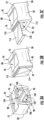
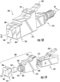
- Figs. 3A-3C illustrate a first embodiment of a cap 70 for covering the distal end of the connector 10 to protect the precision mating surfaces, such as the end face 30 of the ferrule 16, from damage and contamination.
- the cap 70 may have a generally rectangular body 72 (also referred to as "cap body 72") including a top 76, a bottom 78, a first side 82, and a second side 84.
- the top 76 and the bottom 78 may include shoulders that at least partially define a step feature or indentation 88 provided therein to enable an installation personnel's finger, a tool, or the like, to grip the exterior surface of the body to apply and/or remove the cap 70 from the connector 10.
- the body 72 and the step feature 88 are not limited to only the embodiment shown and may be alternatively shaped or configured without departing from this disclosure.
- the cap body 72 has a proximal end 90 (or “first end”) and a distal end 92 (or “second end”) opposite the proximal end.
- Each of the proximal end 90 and the distal end 92 respectively comprise an opening 94, 96.
- An internal passageway, channel, and/or cavity 98 extends between the first opening 94 and the second opening 96 to generally form a sleeve.
- the cavity 98 may include a guide section 102 having grooves 104 configured to receive and mate with protrusions or guide features 106 in the housing 18 of the connector 10.
- the cavity 98 may form a sleeve, it need not closely receive the ferrule 16 of the connector 10, unlike the sleeve of an adapter or the like.
- the body 72 does not contact the ferrule 16 in the embodiment shown and in at least some other embodiments.
- the cap body 72 is configured for being mounted to and at least partially holding the connector 10.
- the guide section 102 may include at least one shoulder or back stop 130 ( Fig. 7 ), or the like.
- the back stop 130 is located at a predetermined position in the cavity 98.
- the proximal end 90 may also include mechanical retention clips or latches 100 that are integral with the body 70 and are configured to mate with the existing retention features on the housing 18 of the connector 10, such as recesses 108 ( Figs. 1 and 2 ) in the sides of the housing 18. Inner ends of the latches 100 are connected to the interior structure of the cap body 72 so that the outer ends of the latches may be moved in a cantilevered manner.
- the distal end 92 includes a front or distal surface 112, and at least one outer closure element or cover 114 is connected to the front surface 112 along a hinge 116.
- the cover 114 may be configured to at least partially or completely cover or obstruct the opening 96 and close or seal the cavity 98.
- the cap 70 may be part of a cap apparatus that further includes a sealing apparatus.
- a variety of sealing apparatuses are within the scope of this disclosure, as discussed in greater detail below. In general, the sealing apparatuses are configured in a manner that seeks to block the transport of contaminates at least to the end face 30 of the ferrule 16.
- the front surface 112 and the interior surface 120 of the cover 114 may include feature(s) and/or be associated with element(s) that form a mechanical seal that seeks to prevent contamination of the cavity 98 by moisture, dust, or any other particles or debris that could enter the cavity 98 and require cleaning before use.
- the features of the mechanical seal may include at least one recess or annular groove 124 that is defined in the front surface 112 and circumscribes the opening 96, and at least one packing element 126 configured for extending at least partially into the annular groove 124.
- the packing element 126 is in the form of an annular packing protrusion extending inwardly from the interior surface of the cover 114.
- the packing protrusion may be formed integrally with the cover 114.
- the packing element 126 is configured to mate with the annular groove 124 to form the seal such that the seal is configured to prevent moisture, debris and other contaminates from entering the cavity 98.
- the packing element 126 may be a length of conventional packing material, an o-ring, or any other suitable packing formed separately from the cover 114.
- the groove 124 and packing element 126 may be collectively referred to as a sealing apparatus.
- the sealing apparatus may be alternatively arranged, configured, or the like, without departing from the disclosure.
- the annular groove 124 may be in the cover 114 and the packing protrusion 126 may be in the front surface 112.
- the mechanical seal may comprise a gasket, O-ring type, labyrinth seal and/or any other suitable seal.
- the body 72 of the cap 70 may be manufactured via a molding process from a plastic material.
- the material can be chosen to minimize or eliminate static electricity that could act to charge the optical connector components.
- the outer cover 114 may be integrally formed with the cap body 72 and the hinge 116 may be a living hinge made of the same material as the body 72, or alternatively the hinge 116 may be made of a different material than the body 72.
- the hinge 116 is connected to the front surface 112, however the hinge 116 may be connected to the body 72 along the top 76, bottom 78, or sides 82, 84.
- the hinge 116 may be a continuous hinge, a barrel hinge, a butt/Mortise hinge, and/or any other suitable hinge(s) that allow the cover 114 to swing or pivot from an open position to a closed position.
- the outer cover 114 may be formed separately from the cap body 72 and then be connected to the cap body with one or more connectors or fasteners, as will be discussed in greater detail below.
- the cap 70 may have a first or open configuration wherein the cover 114 is spaced apart from the front surface 112 of the distal end 92 for allowing access to the interior passageway or cavity 98 of the cap body 72, and a second or closed configuration wherein the cover 114 is substantially proximate or in face-to-face contact with the front surface 112 of the distal end 92 of the cap body 72.
- the cover 114 may include one or more fasteners, such as an attachment clip or lip 132 that extends from the edge of bottom end 134 of the cover.
- the lip 132 is configured to mate with a recess 138 in the bottom surface 78 of the exterior of the cap body 72.
- the cap 70 while the cap 70 is secured closed, the cap at least partially covers and protects the sealing apparatus 124, 126 in a manner that seeks to maintain and protect the functionality of the sealing apparatus.
- the secured closed cap 70 at least by virtue of its attachment clip or lip 132, extends at least partially around the sealing apparatus 124, 126 in a manner that seeks to maintain and protect the functionality of the sealing apparatus.
- the cap apparatus includes a sealing apparatus 74 ("inner closure element") configured to at least partially or completely cover or obstruct the opening 96 and close or seal the cavity 98.
- the sealing apparatus 74 may be positioned between the front surface 112 of the cap body 72 and the interior surface 120 of the cover 114 for restricting any contamination of the cavity 98 by moisture, dust, or any other particles or debris that could enter the cavity 98.
- the sealing apparatus 74 comprises a membrane or sealing film 142 configured to at least partially cover and further seal any migration path for debris through the opening 96 in the distal end 92 of the body 72.
- the sealing apparatus 74 may further include a gel or adhesive layer 144 ( Fig. 7 ) carried by the sealing film 142 for attaching the sealing film in face-to-face contact with one or more portions of the cap body 72.
- the gel or adhesive layer may attach the sealing film 142 to at least one of the following: the first side 82, second side 84, distal surface 92, or the bottom 78 of the cap body 72.
- the gel or adhesive layer 144 may also be configured for trapping/capturing contaminations that may seek to migrate into the cavity 98 or that may have been left inside the cap after the cleaning process.
- the sealing apparatus 74 may be an adhesive tape that includes the sealing film 142 and adhesive layer 144.
- a durably suitable adhesive tape for use as the sealing apparatus 74 may be selected from conventional adhesive tapes.
- the cap 70 with the sealing apparatus 74 maybe referred to as a cap apparatus 148.
- the sealing apparatus 74 is spaced apart from the front end face 30 of the ferrule 16.
- the end face 30, however, remains relatively close to the distal end 92 of cap body 72 and to the cover 114. That is, the connector 10 extends through the first opening 94 ( Fig. 3A ) and into cavity 98 so that the end face is positioned closer to the second opening 96 ( Fig. 3C ) than the first opening.
- at least a portion of the connector 10 may extend at least 60%, or even at least 80%, through the cavity 98 of cap body 72.
- the position of the end face 30 relative to the cap apparatus 148 maybe expressed in a variety of alternative ways.
- the cap body 72 has a length B L between the proximal and distal ends 90, 92.
- the end face 30 may be spaced from the cover 114 by a distance S that is less than 50%, or even less than 25%, of the length B L .
- Fig. 7 also illustrates the ferrule 16 having a front end 150 defining the end face 30, a back end 152 opposite the front end, and a length F L between the front and back ends 150, 152.
- the end face 30 may be spaced from the cover by a distance S that is less than 50%, or even less than 25%, of the length F L .
- the distance S may be less than 5 mm.
- the distance S may be between 0.1 millimeters (mm) and 2.5 mm.
- the adhesive layer 144 may include any adhesive material that is effective for causing any loose particles inside the cavity 98 to become secured to the sealing film 142 without concern for leaving adhesive residue on the front end face 30 of the ferrule 16.
- the sealing apparatus 74 includes a gel or adhesive layer comprised of a first region 136 with a first adhesive material for attaching the sealing film to the exterior of the cap body 72 and a second region 140 with a second adhesive material, different from the first adhesive material, for trapping particles that are inside the cavity 98.
- the second region 140 may comprise a stronger adhesive material than the first region 136.
- the first region 136 may comprise a stronger adhesive material than the second region 140.
- the adhesive layer provides at least an area of adhesive material that confronts (e.g., be in opposing face-to-face relation with) the front end face 30 of the ferrule 16, yet is also spaced apart from the front end face of the ferrule. Any particulate contaminants may become attached to the area of adhesive material such that the adhesive material may provide a cleaning function.
- the sealing apparatus 74 may be made from materials that minimize or eliminate contamination to the connector 10 and the ferrule 16 resulting from environmental effects and/or aging effects such as outgassing.
- the sealing film 142 may be made from materials including metal foil applied via induction sealing, plastic film applied via heat shrink processes, or tapes or films applied with adhesives.
- the sealing film 142 may be made from an optically translucent or transparent material that allows for visual inspection of light transmission through the sealing film when the outer cover 114 is open thus allowing visual inspection without the removal of the cap 70 from the connector 10.
- the outer cover 114, and perhaps the body 72, may be opaque in such an embodiment such that the aforementioned visual inspection is only possible when the outer cover 114 is open.
- the material of the outer cover 114 could also be translucent or transparent for allowing visual inspection of light transmission through the sealing film 142 and the outer cover 114 when the outer cover 114 is closed.
- the connector 10 having the ferrule 16 is provided.
- the end face 30 of ferrule 16 is inserted into the opening 94 in the proximal end 90 of the cap body 72 until the front end 26 of the housing 18 abuts the back stop 130 and/or the latches 100 mate with the recesses 108 ( Figs. 1 and 2 ) in the sides of the housing 18 to secure the cap 70 to the connector 10.
- the outer cover 114 Before or after the cap 70 is mounted to the connector 10, the outer cover 114 may be opened, i.e. moved to its open configuration ( Fig. 6A ). After the cap 70 has been mounted to the connector 10 and while the outer cover 114 is open, the cleaning process may be conducted, such as by providing (e.g., spraying) a cleaning fluid into the cavity 98, as schematically shown in Fig. 6B . Pressurized air, water, chemical solutions, or any other suitable cleaning agents may be used to clean the combination 149, specifically inside the portion of the cavity 98 that extends forwardly from the end face 30 of the ferrule 16. Some examples of other cleaning methods known in the art include ultrasonic cleaning, agitated bath, and clean/dry high purity gas processing.
- a drying step may be included for some of the cleaning methods that utilize liquids.
- the drying step may allow and/or cause dry air or other suitable gas(es) to flow into the open portion of the cavity 98.
- ionized air may be included to help neutralize any static charge effects before mounting the sealing film 142 to the cap 70.
- the sealing apparatus 74 may be applied to the distal end 92 of the cap body 72 for obstructing, or more specifically closing and sealing the opening 96, as shown in Fig. 6C .
- the cover 114 may be moved to its closed position ( Fig. 6D ).
- the sealing apparatus 74 and the opening 96 are at least partially, substantially, or completely covered by the outer cover 114 to further seal the opening 96 of the cap body 72.
- the cap 70 which is secured closed at least by virtue of its fastener clip or lip 132, extends at least partially around the sealing apparatus 74 in a manner that seeks to maintain and protect the functionality of the sealing apparatus.
- the sealing apparatus 74 may be adhesive tape, or the like, that is applied to the distal end 92 of the cap body 72, for obstructing, or more specifically closing and sealing, the opening 96.
- the sealing apparatus 74 may be in the form of a sealing plug, as discussed in greater detail below.
- the sealing plug may be inserted through the opening 96 into the chamber 98.
- the sealing plug in such an embodiment may not only confront (e.g., be in opposing face-to-face relation with) the front end face 30 of the ferrule 16, but may also conformingly engage the front end face of the ferrule. Again, these and other aspects will be discussed in greater detail below.
- the cap apparatus 148 may be removed from the connector 10 after the cavity 98 of the body 72 has been sealed closed for a period of time.
- the cap may be manually removed from the connector, such as by manually pulling the slider 20 ( Figs. 1 and 2 ) of the connector rearwardly, and then by overcoming the bias of the latches 100 of the cap.
- the cover 114 may remain closed and the sealing apparatus 74 may remain fixedly connected to the cap, so that the sealing apparatus is removed with the cap.
- the reason the cap 70 (or, more generally, cap apparatus 48) is removed may be for mating purposes with a second connector (not shown), as the cap apparatus itself is not configured to mount to a second fiber optic connector or otherwise couple the connector 10 to a second fiber optic connector.
- the connector 10 may be inserted into an adapter (not shown) after removing the cap 70 without any further cleaning of the end face 30.
- the adapter may be used to mate the connector 10 with another similar fiber optic connector.
- the adapter may include an alignment sleeve used to align the ferrule 16 of connector 10 with a ferrule of the similar connector.
- Figs. 8-10 illustrate a cap 270 and a sealing apparatus 74 of a second embodiment of the disclosure having similar features as the first embodiment.
- the first and second embodiments can be alike, except for variations noted and variations that will be apparent to those of ordinary skill in the art. Accordingly, similar or identical features of the embodiments are provided with like or identical reference numbers.
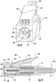
- Fig. 8 illustrates the body 272 of the cap 270 mounted to a single-fiber connecter 210, such as for facilitating a cleaning process substantially like that discussed above.
- the body 272 has an attachment feature 231 for releasably mating with the attachment feature 232 of the connector 210.
- the attachment features 231, 232 typically include latching elements that become latched to one another to securely hold the body 272 and the connector 210 together, wherein this latching may be released by depressing the attachment feature 232 of the connector 210.
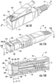
- Fig. 9 illustrates the cap 270 with the sealing apparatus 74 confronting the ferrule 216 to aid in collection of contamination particles that may propagate or migrate into and/or around the sealed chamber 246.
- the cover 214 may be pivotably attached to the body 272 of the cap 270 by a hinge 216 comprising a hinge pin 217 or the like, so that the cover may be moved, or more specifically pivoted, between open and closed positions.
- the sealing apparatus 74 which may be in the form of adhesive tape or another suitable material discussed above, may be mounted to the distal end 292 of the body 272 so as to at least obstruct, or close and seal the opening 294 to the cavity 298 within the body.
- an area of adhesive material that may be part of the adhesive layer 144 may both confront (e.g., be in opposing face-to-face relation with) the front end face 230 of the ferrule 216, and be spaced apart from the front end face of the ferrule.
- the cap 270 with the sealing apparatus 74 maybe referred to as a cap apparatus 248.
- Figs. 11A and11B illustrate a cap 370 of a third embodiment of the disclosure having similar features as the first embodiment.
- the first and third embodiments can be alike, except for variations noted and variations that will be apparent to those of ordinary skill in the art. Accordingly, similar or identical features of the embodiments are provided with like or identical reference numbers.
- the sealing apparatus comprises a plug 342 that is positioned in the cavity 398 of the cap body 372.
- the plug 342 may substantially fill and seal the forward portion of the cavity 398 of the cap body 372 and/or substantially completely cover the end face 30 of the ferrule 16 in a manner that seeks to prevent any foreign contamination from entering the cavity 398 and/or depositing on the end face 30.
- the plug 342 may consist of elastomeric material, such as a UV-curable elastomeric material, a UV-curable rubber material, or any other suitable material.
- the plug 342 may comprise rubbery polymer materials such as those disclosed in U.S. Patent Nos. 7,232,595 , 7,256,221 and 7,723,441 .
- the plug 342 may have a modulus of elasticity that is greater than the modulus of elasticity of the cap body 372.
- a gap between the interior surface 320 of the cover 314 and the front end face 30 of the ferrule 16 has a lengthwise dimension L1.
- the sealing plug 342 has a lengthwise dimension L2 that may be coaxial with the lengthwise dimension L1.
- the lengthwise dimension L2 may be at least the same magnitude as, or greater than, the lengthwise dimension L1.
- the inner end face of the plug 342 may be substantially planar prior to the inner end face of the plug 342 engaging the ferrule 16. Then, when the plug 342 engages the front end face 30 of the ferrule 16, the central area or another suitable portion of the inner end face of the plug may be engaged by and compressed by the front end face of the ferrule, so that the plug extends at least partially around the front end face of the ferrule 16.
- the interior walls of the cap body 372 may be angled and/or the cap body may include an inwardly protruding shoulder 373 that engages the inner end face of the plug 342, so that the cap 370 carries the plug away from the connector 10 when the cap is removed from the connector.
- the cap 370 with the plug 342 therein may be referred to as a cap apparatus 348.
- the plug 342 is typically positioned in, or more specifically fixedly mounted in, the cavity 398 of the cap body 372, and the cover 314 is secured closed, such as by of the hinge 316, attachment clip or lip 332 and recess 338, or the like, prior to the cap apparatus 348 being mounted to the connector 10.
- the plug 342 is typically not removable from the cap 370, although variations are within the scope of this disclosure.
- the method includes forming the plug 342 ( Figs. 14A and 15B ) in the cap body 372 ( Figs. 13A-15B ), by defining a mold cavity 400 ( Figs. 13A and 13B ) in the cap body, and molding the plug in the mold cavity.
- the mold cavity 400 is partially defined by the cavity 398 of the cap body 372, and further partially defined by a mold tool 401 ( Figs. 12A and 12B ) removably positioned in the cap body 372.
- each mold tool 401 is similar to the exterior shape of the forward portions of the mated together housing 18, ferrule 16, and guide pins 44, except that a ferrule-shaped portion 416 of the mold tool does not extend as far outwardly from a housing-shaped portion 418 of the mold tool, and pin-shaped portions 444 of the mold tool are oversized.
- the mold tools 401 may extend outwardly from a suitable holding apparatus 402, jig, base, or the like.
- the cap 370 may be mounted to the mold tool 401. This mounting may include causing relative movement between the cap body 372 and the mold tool 401 so that: a) the mold tool extends through the opening 394 to the cavity 398 ( Fig. 13B ) of the cap body, b) the end face 430 ( Fig. 12B ) of the ferrule-shaped portion 416 of the mold tool is positioned in the cavity 398, and c) the mold cavity 400 ( Figs. 13A and 13B ) is at least partially defined by the end face of the mold tool.
- the cap 370 may be attached to the mold tool 401 by way of the retention clips or latches 100 ( Figs.
- the plug 342 ( Figs. 14A and 15B ) is formed in the mold cavity 400 by substantially fully filling the mold cavity with a suitable UV-curable elastomeric molding material, examples of which are discussed above, followed by solidifying the plug-forming molding material.
- a suitable UV-curable elastomeric molding material examples of which are discussed above, followed by solidifying the plug-forming molding material.
- ultraviolet light may be used to cure the plug-forming molding material into a solid and thereby form the plug 342, so that the plug is typically fixedly positioned in the cavity 398 of the cap body 372.
- the plug 342 typically substantially fills both the mold cavity 400 and the opening 396 to the cavity of the cap body.
- the cover 314 may be secured in the second or closed position wherein the cover 314 is confronting, such as by being in face-to-face contact with, the distal end 392 of the cap body 372 for further sealing the opening 396 ( Figs. 13A and 13B ) of the cap body.
- the cap apparatus 348 may be removed from the associated mold tool 401 by overcoming the bias of the latches 100 of the cap apparatus to release the latches from the recesses 408 of the mold tool.
- the cap apparatus 348 may be mounted to a fully assembled connector 10, such as after at least the exposed portions of the ferrule 16, housing 18, and guide pins 44 have been cleaned, so that the cap apparatus seals and protects the precision mating surfaces, such as the end face 30 of the ferrule 16, from damage and contamination.
- an inner end face of the plug 342 engages the front end face 30 of the ferrule 16, or more specifically conformingly contacts and thus extends at least partially around the front end face 30 of the ferrule 16.
- the inner end face of the plug may be substantially planar.
- the central area or another suitable portion of the of the inner end face of the plug may be engaged by and compressed by the front end face of the ferrule, so that the plug extends at least partially around the front end face of the ferrule 16.
- the guide pins 44 may fit with clearance into receptacles formed in the plug 342, so that gaps are present between the guide pins and the plug. As a result, the guide pins do not interfere with the front end face 30 of the ferrule 16 engaging and deforming the plug.
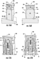
- the inner surface 320 of the cover 314 may include a recess or cavity 321, and the plug 342 may deform into the cavity 321 in response to the front end face 30 of the ferrule 16 engaging and deforming the plug, as shown in Figs. 17A and 17B .
- the plug 342 may be fixedly molded into the cavity 398 of the body 72 of the cap apparatus 348.
- the plug 342 may be formed separately from the cap apparatus 348 and thereafter be inserted into the cavity 398 of the body 72 of the cap 70, such as after the cavity 398, the front end face 30 of the ferrule 16, and associated features are simultaneously cleaned, as generally discussed above.
- the plug 342 may be configured for use with a variety of connectors and cap apparatuses.
- a fourth embodiment of this disclosure can in some ways be like each of the second and third embodiments, except for variations noted and variations that will be apparent to those of ordinary skill in the art. For example and referring to Figs.
- the sealing apparatus of the cap apparatus 548 of the fourth embodiment is in the form of a plug 542 that may be generally like the plug 342 of the third embodiment, except for variations noted and variations that will be apparent to those of ordinary skill in the art. Accordingly, similar or identical features of the embodiments are provided with like or identical reference numbers.
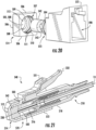
- Figs. 18 and 21 illustrate the body 572 of the cap 570 mounted to the single-fiber connecter 210, and a cover 514 mounted to the body.
- the body 572 has an attachment feature 531 for releasably mating with the attachment feature 232 of the connector 210.
- the body 572 of the cap 570 includes annular internal and external shoulders 502, 503 for respectively engaging the forward edge of the housing 218 of the connector 210 and the rear edge of the cover 514 of the cap.
- the body 572 of the cap 570 and the cavity 598 therein transition between rearward and forward sections proximate the shoulders 502, 503.
- the rearward section of the cavity 598 substantially conforms in shape to the exterior of the housing 218 of the connector 210; the forward, cylindrical section of the cavity 598 substantially conforms in shape to the cylindrical exterior of the plug 542; and the exterior of the forward section 573 of the body 572 substantially conforms in shape to the an interior portion of the cover 514.
- the forward section 573 of the body 572 comprises a cylindrical wall or sleeve with one or more fastener features in the form of outwardly open, annular fastening grooves 504 for at least partially facilitating mounting of the cover 514 to the forward section 573 of the body 572.
- the cover 514 includes a forward wall 505, and one or more side walls 506 extending rearwardly from the periphery of the forward wall and around a tiered internal cavity 507 of the cover 514. Referring to Fig.
- the tiered cavity 507 of the cover 514 is defined by a disk-shaped inner surface 508 of the forward wall 505; a cylindrical, forward inner surface 508 of the sidewalls 506; an annular inner shoulder 509 of the sidewalls; and a cylindrical, rearward inner surface 510 of the sidewalls.
- the cylindrical, forward inner surface 508 has a smaller diameter than the cylindrical, rearward inner surface 510.
- One or more fastener features in the form of annular protrusions 511 extend inwardly from the rearward cylindrical surface 510 for respectively extending into and engaging the annular fastening grooves 504 for at least partially facilitating mounting of the cover 514 to the forward section 573 of the body 572.
- the positions of the fastening grooves and protrusions 504, 511 may be reversed and/or the fastening grooves and protrusions may be replaced by or supplemented with other suitable fastening features.
- the substantially cylindrical forward section 573 of the body 572 has an outer diameter that substantially corresponds to the diameter of the rearward inner surface 510 of the cover 514.
- the substantially cylindrical forward section 573 of the body 572 has an inner diameter that substantially corresponds to both the outer diameter of the plug 542 and the diameter of the forward inner surface 508 of the cover 514. Accordingly and as best understood with reference to Fig. 21 , the plug 542 can fit coaxially and snugly into both the forward portion of the cavity 598 of the cap body 572 and the forward portion of the tiered cavity 507 of the cover 514.
- each of the cover 514 and the forward section 573 of the body 572 extend at least partially around, or more specifically extend completely around, the plug 542. As shown in Fig.
- the plug 542 is compressed between the front face 230 of the ferrule 216 and the inner surface 508 of the front wall 505 of the cover 514.
- the plug 542 may be constructed of an elastomeric material, as discussed above, so that the central area or another suitable portion of the of the inner end face of the plug is engaged and compressed by the front end face 230 of the ferrule 216, so that the plug 542 extends at least partially around the front end face of the ferrule.
- the plug 542 may be constructed of any suitable molding materials discussed above, for example so that the plug 542 may have a modulus of elasticity that is greater than the modulus of elasticity of the cap 570.
- the plug 542 may be constructed of an elastomeric foam, and the plug 542 may also have adhesive properties.
- stippling schematically represents a gel or adhesive layer on the inner end of the plug 542. Therefore, in addition to the plug 542 being able to seal and protect a previously cleaned end face 230 of the ferrule 216, the adhesive properties or adhesive material associated with the inner end of plug 542 may help to collect any contaminants that may be present and, thus, provide a cleaning function.
- any adhesive material associated with the inner end of plug 542 will be operative to release more readily from the end face 230 of the ferrule 216 than from the plug, so that adhesive residue is not left on the end face of the ferrule 216 when the cap apparatus 548 is removed from the connector 210.
- the adhesive material may be omitted from a central area 543 of the inner end face of the plug 542, so that the central area 543 is at least partially surrounded, or substantially surrounded, by a region of adhesive material on the inner end face of the plug 542.
- the end face 230 of the ferrule 216, or at least the end of the optical fiber 13, may engage the central area 543 of the inner end face of the plug 542.
- a vent hole 512 may extend through the forward wall 505 of the cover 514 to the tiered cavity 507 within the cover, for releasing any partial vacuum associated with the removal.
- caps, cap apparatuses, and sealing apparatuses are within the scope of this disclosure.
- cylindrically-shaped features of the cap 570, cover 514, and plug 542 are discussed above, those features may be shaped differently, such as by being rectangular or in any other suitable shape.
- rearward section of the cover 514 is generally described above as fitting over and onto the forward section 573 of the cap body 572, the rearward section of the cover may alternatively fit into the forward section of the cap body, as discussed in greater detail below.
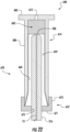
- the at least one sidewall 606 of the cover 614 fits into the forward section 673 of the cap body 672, and the sidewall 606 and the forward section 673 are cooperatively configured so that an interference-fit type of connection is defined therebetween.
- the connection between the cover 614 and the cap body 672 may be provided in any other suitable manner, such as by way of interacting fastening grooves and protrusions, as discussed above.
- the fifth embodiment and the fourth embodiment can be alike, except for variations noted and variations that will be apparent to those of ordinary skill in the art. Accordingly, similar or identical features of the embodiments are provided with like or identical reference numbers.
- the cap body 672 comprises a rearward wall 671 and the forward section 673 of the cap body extends forwardly from the periphery of the rearward wall 671.
- the rearward wall 671 includes a cylindrical, central hole 675 through which the ferrule 216 is inserted.
- the diameter of the hole 675 may be only slightly larger than the outer diameter of the ferrule 216 so that the during the relative movement between the rearward wall 671 and ferrule 216, which occurs during installation of the cap apparatus 648, the rearward wall 671 may wipe the outer cylindrical sidewall of the ferrule 216 clean.
- a gap between the outer cylindrical sidewall of the ferrule 216 and the inner surface of the sidewall 606 of the cover 614.
- a sticky coating of adhesive material 644, or the like may be fixedly adhered to the inner surface of the sidewall 606, so that any solid contaminants that come into contact with the adhesive material may become adhered to the adhesive material and, thus, be secured to the sidewall 606 and prevented from contaminating the front end face 230 of the ferrule 216.
- the plug 642 may be constructed of an elastomeric material, as discussed above, so that the central area or another suitable portion of the of the inner end face of the plug is engaged and compressed by the front end face 230 of the ferrule 216, so that the plug 642 extends at least partially around the front end face of the ferrule.
- the plug 642 may have a modulus of elasticity that is greater than the modulus of elasticity of the cap body 672.
- the plug 642 may be constructed of an elastomeric foam, and the plug 642 may also have adhesive properties.
- any adhesive material associated with the inner end of plug 642 will be operative to release more readily from the end face 230 of the ferrule 216 than from the plug, so that adhesive residue is not left on the end face of the ferrule 216 when the plug 642 is removed from the ferrule 216.
- a vent hole 612 may extend through the forward wall 605 of the cover 614, for releasing any partial vacuum associated with the removal.
- An aspect of this disclosure is the provision of methods and features for cleaning and maintaining the cleanliness of fiber optic connectors.
- one aspect of this disclosure is the provision of features for sealing fiber optic connectors, such as after factory cleaning, until the time they are installed in the field.
- this disclosure describes "blockers” (e.g., sealing features) and “getters” (e.g., adhesive features) that are operative to inhibit any transport of contamination to clean end faces 30, 230 of ferrules 16, 216.
- An aspect of this disclosure is the provision of a material, which may be in the form of a plug 342, 542, 642, that may be positioned at least partially inside of at least a portion of a cap 70, 270, 370, 570, 670 or a cap apparatus 348, 548, 648, and that may conformingly contact the end face 30, 230 of a ferrule 16, 216 in a manner that seeks to prevent any contamination from transporting to the critical optical area of the associated optical fiber(s) 13.
- the material, which may be in the form of a plug 342, 542, 642 may be compliant and resilient such that the end faces 30, 230 of the ferrules 16, 216 can push into this material. In addition, this material can contain or carry other materials that may enhance or improve other properties.
- the plugs 342, 542, 642 may also include an antistatic feature or material, which seeks to prevent any static charge from building up on connector end faces 30, 230 of the ferrules 16, 216, since any such static charges may tend to attract airborne dust particles when the caps 70, 270, 370, 570, 670 and/or cap apparatuses 348, 548, 648 are removed.
- the plugs 342, 542, 642 may have a sticky surface that may function as a cleaning agent and a trap for external contamination.
- the conformable material which may be in the form of a plug 342, 542, 642, may block any contaminants from reaching the end face 30, 230 of a ferrule 16, 216, and any associated adhesive material may function to trap any contaminates so that the contaminates do not reach, or are removed from, the end face 30, 230 of the ferrule 16, 216.
- the conformable material may include rubber, foam, silicone, cloth, woven material, sponge, a sticky material and/or any other suitable material.
- the each plug 342, 542, 642 may be constructed of a hard material that may include a sticky material that may, in one example, be in close proximity to, yet spaced from, the end face 30, 230 of the ferrule 16, 216.
- the material, which may be in the form of a plug 342, 542, 642 may be treated so that so that it can hold another material or bloom another material to its surface after manufacturing to enhance other parameters.
- the material, which may be in the form of a plug 342, 542, 642 may have: properties that control static, such as by reducing, eliminating or enhancing static electricity; anti-stick properties; sticky properties; hydrophobic properties; non-spalling properties; non-particulating properties; lubricating properties and/or optical index matching properties.
- the material may impart optical index matching properties to the ferrule end faces 30, 230, so that the ferrule end faces retain the optical index matching properties after the plugs 342, 542, 642, or the like, are removed.
- the optical index matching properties of the material, which may be in the form of the plugs 342, 542, 642, may be imparted through the use of additives or depositing appropriate materials on the respective surfaces of the plugs 342, 542, 642, or the like.
- an additive may be a substance that blooms to the respective surfaces of the plugs 342, 542, 642, or the like, and leaves a thin layer of a waxy substance, or the like, on the associated end surfaces of the optical fibers 13, wherein the waxy substance, or the like, may have anti-static, anti-stick and/or index matching properties.
- appropriate areas of the connectors 10, 210 may be cleaned in the factory, and then the clean end faces 30, 230 of the ferrules 16, 216 are sealed with the cap apparatuses 148, 248, 348, 548, 648, which may be later removed in the field for installation.
Landscapes
- Physics & Mathematics (AREA)
- General Physics & Mathematics (AREA)
- Optics & Photonics (AREA)
- Mechanical Coupling Of Light Guides (AREA)
Claims (11)
- Faseroptikkabelbaugruppe (14), umfassend:ein Kabel (12) mit mindestens einer optischen Faser (13) ;mindestens einen faseroptischen Verbinder (10, 210), der an einem Ende des Kabels (12) montiert ist, wobei der faseroptische Verbinder (10) eine Pressklemme (16) hat, durch die sich die mindestens eine optische Faser (13) erstreckt; undeine Kappenvorrichtung (148), der an mindestens einem Abschluss des faseroptischen Faserverbinders montiert ist, um zumindest eine Endfläche (30) der Pressklemme (16) zu schützen, wobei die Kappenvorrichtung (148) umfasst:einen Körper (72) mit entgegengesetzten proximalen und distalen Enden (90, 92), zwischen denen sich ein Hohlraum (98) erstreckt, wobei das proximale Ende (90) eine erste Öffnung (94) zum Hohlraum (98) definiert, und das distale Ende (92) eine zweite Öffnung (96) zu mindestens einem Abschnitt des Hohlraums (98) definiert,wobei sich zumindest ein Abschnitt des faseroptischen Verbinders (10, 210) durch die erste Öffnung (94) und in den Hohlraum (98) erstreckt, so dass sich die Endfläche (30) der Pressklemme (16) näher an der zweiten Öffnung (96) als die erste Öffnung (94) befindet;eine Abdeckung (114), die am Körper (72) montiert und schwenkbeweglich an den Körper (72) angeschlossen ist und zumindest teilweise die zweite Öffnung (96) verdeckt, wobei sich die Endfläche (30) der Pressklemme (16) in dem Hohlraum (98) an einer Stelle befindet, die von der Abdeckung (114)beabstandet ist; undeine Abdichtungsvorrichtung (74), die sich zwischen zumindest einem Abschnitt der Abdeckung (114) und der Endfläche (30) der Pressklemme (16) befindet,wobei die Abdichtungsvorrichtung (74) zumindest einen Abschnitt des Hohlraums (98) abdichtet,wobei die Abdeckung beweglich am Körper montiert ist, so dass die Abdeckung beweglich ist zwischen: einer geschlossenen Auslegung, in der die Abdeckung zumindest teilweise die zweite Öffnung verdeckt; und einer offenen Auslegung, in der zumindest ein Abschnitt der Abdeckung weiter weg von der zweiten Öffnung ist, als wenn die Abdeckung in der geschlossenen Auslegung ist; und sich die Abdeckung zumindest teilweise um die Abdichtungsvorrichtung (74) herum erstreckt;dadurch gekennzeichnet, dass die Abdichtungsvorrichtung eine Fläche von adhäsivem Material umfasst, das sowohl: der Endfläche der Pressklemme zugewandt und von der Endfläche der Pressklemme beabstandet ist: wobei die Abdichtungsvorrichtung einen Abdichtungsfilm (142) umfasst, der dazu ausgelegt ist, zumindest teilweise irgendeinen Wanderpfad für Abfall durch die zweite Öffnung im distalen Ende (92) des Körpers abzudecken und weiter abzusiedeln; wobei die Abdichtungsvorrichtung eine adhäsive Schicht(144) enthält, die von dem Abdichtungsfilm (142) getragen ist, um den Abdichtungsfilm in einem Augenkontakt mit einem oder mehreren Abschnitten des Körpers anzubringen; die adhäsive Schicht einen erste Bereich (136) mit einem ersten adhäsiven Material, um den Abdichtungsfilm (142) außen am Körper anzubringen, und einen zweiten Bereich mit einem zweiten adhäsiven Material umfasst, das sich vom ersten adhäsiven Material unterscheidet, um Partikel einzufangen, die sich im Inneren des Hohlraums sind.
- Faseroptikkabelbaugruppe nach Anspruch 1, wobei die Kappenvorrichtung nicht dazu ausgelegt ist, an einem zweiten faseroptischen Verbinder zu montieren, wobei die Kappenvorrichtung nicht dazu ausgelegt ist, den faseroptischen Verbinder mit einem zweite faseroptischen Verbindet zu verbinden; und
wobei der Körper der Kappenvorrichtung die Pressklemme nicht berührt. - Faseroptikkabelbaugruppe nach Anspruch 1 oder 2, wobei sich der zumindest eine Abschnitt des faseroptischen Verbinders mindestens 60% durch den Hohlraum des Körpers erstreckt.
- Faseroptikkabelbaugruppe nach einem der Ansprüche 1 bis 3, wobei der Körper der Kappenvorrichtung eine Länge BL zwischen den proximalen und distalen Enden des Körpers hat, und wobei darüber hinaus die Endfläche der Pressklemme von der Abdeckung um einen Abstand S beabstandet ist, der kleiner ist als 0,25*BL.
- Faseroptikkabelbaugruppe nach einem der Ansprüche 1 bis 4, wobei die Pressklemme des faseroptischen Verbinders ein vorderes Ende, das die Endfläche definiert, ein hinteres Ende, das dem Vorderende entgegengesetzt ist, und eine Länge FL zwischen dem vorderen und hinteren Ende enthält, und wobei darüber hinaus die Endfläche der Pressklemme von der Abdeckung um einen Abstand S beabstandet ist, der kleiner ist als 0,5*FL.
- Faseroptikkabelbaugruppe nach Anspruch 5, wobei der Abstand S zwischen 0,1 mm und 2,5 mm beträgt.
- Faseroptikkabelbaugruppe nach einem der Ansprüche 1 bis 6, wobei die Abdeckung ein Befestigungsmittel enthält, das die Abdeckung am Körper befestigt; und
wobei sich die Abdeckung in den Hohlraum des Körpers erstreckt. - Faseroptikkabelbaugruppe nach einem der Ansprüche 1 bis 7, wobei die Abdichtungsvorrichtung ein Klebeband umfasst, und das Klebeband die Fläche des adhäsiven Materials umfasst.
- Faseroptikkabelbaugruppe nach Anspruch 8, wobei das Klebeband am Körper montiert ist und zumindest teilweise die zweite Öffnung verdeckt.
- Faseroptikkabelbaugruppe nach Anspruch 9, wobei die zweite Öffnung abgedichtet, geschlossen durch das Klebeband ist.
- Faseroptikkabelbaugruppe nach einem der Ansprüche 9 bis 10, wobei:das Äußere des Körpers entgegengesetzte erste und zweite Seiten (82, 84) umfasst; unddie Fläche adhäsiven Materials ist an der ersten Seite (82) des Äußeren des Körpers in Angriff, unddie Fläche des adhäsiven Materials ist an der zweiten Seite (84) des Äußeren des Körpers in Angriff.
Applications Claiming Priority (3)
| Application Number | Priority Date | Filing Date | Title |
|---|---|---|---|
| US201562167957P | 2015-05-29 | 2015-05-29 | |
| EP15173169.2A EP3098633A1 (de) | 2015-05-29 | 2015-06-22 | Kappenvorrichtungen zum versiegeln von faseroptischen verbindern und zugehörige verfahren |
| PCT/US2016/030925 WO2016195901A1 (en) | 2015-05-29 | 2016-05-05 | Fiber optic cable assemblies with cap apparatuses for sealing optical fiber connectors and associated methods |
Publications (2)
| Publication Number | Publication Date |
|---|---|
| EP3304152A1 EP3304152A1 (de) | 2018-04-11 |
| EP3304152B1 true EP3304152B1 (de) | 2023-11-22 |
Family
ID=53476754
Family Applications (2)
| Application Number | Title | Priority Date | Filing Date |
|---|---|---|---|
| EP15173169.2A Withdrawn EP3098633A1 (de) | 2015-05-29 | 2015-06-22 | Kappenvorrichtungen zum versiegeln von faseroptischen verbindern und zugehörige verfahren |
| EP16767051.2A Active EP3304152B1 (de) | 2015-05-29 | 2016-05-05 | Faseroptische kabelanordnungen mit kappvorrichtungen zur versiegelung von glasfaserverbindern |
Family Applications Before (1)
| Application Number | Title | Priority Date | Filing Date |
|---|---|---|---|
| EP15173169.2A Withdrawn EP3098633A1 (de) | 2015-05-29 | 2015-06-22 | Kappenvorrichtungen zum versiegeln von faseroptischen verbindern und zugehörige verfahren |
Country Status (5)
| Country | Link |
|---|---|
| US (1) | US10133010B2 (de) |
| EP (2) | EP3098633A1 (de) |
| CN (1) | CN107710043A (de) |
| MX (1) | MX376672B (de) |
| WO (1) | WO2016195901A1 (de) |
Families Citing this family (29)
| Publication number | Priority date | Publication date | Assignee | Title |
|---|---|---|---|---|
| USD333144S (en) * | 1990-10-03 | 1993-02-09 | Canon Kabushiki Kaisha | Chamber for semiconductor fabricating machine |
| EP3978974B1 (de) * | 2009-09-28 | 2025-02-19 | TE Connectivity Nederland B.V. | Dichtungsgehäuse für einen verbinder an einem kabel wie z. b. einem standardisierten glasfaserverbinder |
| USD800660S1 (en) * | 2015-06-05 | 2017-10-24 | Corning Optical Communications LLC | Fiber optic connector |
| USD800659S1 (en) * | 2015-06-05 | 2017-10-24 | Corning Optical Communications LLC | Fiber optic connector |
| USD823255S1 (en) * | 2016-08-05 | 2018-07-17 | Corning Optical Communications LLC | Fiber optic connector |
| US10146014B2 (en) * | 2017-01-23 | 2018-12-04 | Corning Optical Communications LLC | Fiber optic assembly and method including pin section(s) for retaining fiber optic connector |
| US10866369B2 (en) * | 2017-03-20 | 2020-12-15 | Senko Advanced Components, Inc. | Gel stick cleaner with reusable handle and disposable cartridge |
| CN109212677A (zh) * | 2017-07-06 | 2019-01-15 | 科大国盾量子技术股份有限公司 | 一种光纤法兰保护装置 |
| JP1598021S (de) * | 2017-08-02 | 2018-02-19 | ||
| JP1598020S (de) * | 2017-08-02 | 2018-02-19 | ||
| EP3461388A1 (de) * | 2017-09-28 | 2019-04-03 | Koninklijke Philips N.V. | Optische verbindungsvorrichtung und verfahren |
| WO2019104273A1 (en) * | 2017-11-25 | 2019-05-31 | Smith Jack William | Dust and port idetification cap for fiber optic adapters |
| TWI662754B (zh) * | 2018-05-14 | 2019-06-11 | 普泰光電股份有限公司 | 具有清潔功能之光纖連接器的防塵件 |
| CN110174727A (zh) * | 2018-05-30 | 2019-08-27 | 中航光电科技股份有限公司 | 一种尾部护套及使用该尾部护套的连接器 |
| CN110174728A (zh) * | 2018-05-30 | 2019-08-27 | 中航光电科技股份有限公司 | 连接器及其尾部护套 |
| WO2020097621A1 (en) * | 2018-11-11 | 2020-05-14 | Senko Advanced Components, Inc | In-line hinged dust shutter assembly for a fiber optic connector |
| US12298569B2 (en) * | 2018-11-14 | 2025-05-13 | Us Conec Ltd. | Guide pin holder for guide pins in an adapter |
| US11971586B2 (en) | 2018-11-21 | 2024-04-30 | Commscope Technologies Llc | Fiber optic connector end face encapsulant forming and curing device |
| USD892059S1 (en) * | 2019-01-08 | 2020-08-04 | Medline Industries, Inc. | ECG cable connector |
| USD892060S1 (en) * | 2019-01-08 | 2020-08-04 | Medline Industries, Inc. | ECG lead wire connector |
| US11668881B2 (en) * | 2019-09-18 | 2023-06-06 | Senko Advanced Components, Inc. | Cleaning stick guide |
| US11422314B2 (en) * | 2020-09-22 | 2022-08-23 | Clearfield, Inc. | Dustcap with built-in cleaner |
| US11681108B2 (en) | 2020-09-22 | 2023-06-20 | Clearfield, Inc. | Dustcap with built-in cleaner |
| US12474531B2 (en) | 2020-09-22 | 2025-11-18 | Clearfield, Inc. | Adapter dustcap with built-in cleaner |
| TWI784427B (zh) * | 2020-11-13 | 2022-11-21 | 立佳興業股份有限公司 | 光電連接器 |
| TWI781766B (zh) | 2021-09-17 | 2022-10-21 | 立佳興業股份有限公司 | 連接埠追尋件 |
| EP4160285B1 (de) * | 2021-09-29 | 2025-11-05 | Corning Research & Development Corporation | Faseroptische verbinder mit einer auf dem verbindergehäuse angeordneten dichtungsmembran |
| EP4540643A4 (de) * | 2022-06-17 | 2026-04-29 | Commscope Technologies Llc | Staubkappe für glasfaserverbinder mit verbesserter verbinderschnittstelle |
| EP4664170A1 (de) * | 2024-06-10 | 2025-12-17 | Clearfield, Inc. | Adapter-staubschutzkappe mit eingebautem reiniger |
Family Cites Families (45)
| Publication number | Priority date | Publication date | Assignee | Title |
|---|---|---|---|---|
| AU635172B2 (en) | 1991-05-13 | 1993-03-11 | Nippon Telegraph & Telephone Corporation | Multifiber optical connector plug with low reflection and low insertion loss |
| US5506922A (en) * | 1994-08-01 | 1996-04-09 | Molex Incorporated | Fiber optic component assembly with a movable protective shield |
| US6227717B1 (en) | 1997-12-16 | 2001-05-08 | The Siemon Company | Dust caps for use with telecommunications adapters and connectors |
| JP3389883B2 (ja) * | 1999-04-23 | 2003-03-24 | 東レ株式会社 | 光コネクタ用清掃具 |
| US6554485B1 (en) | 2000-09-11 | 2003-04-29 | Corning Cable Systems Llc | Translucent dust cap and associated method for testing the continuity of an optical fiber jumper |
| US6547450B2 (en) | 2001-06-27 | 2003-04-15 | Fitel Usa Corp. | Quick-release dust cap for an optical plug |
| DE20201170U1 (de) | 2002-01-15 | 2002-05-29 | Infineon Technologies AG, 81669 München | Vorrichtung zum Schutz der Steckeraufnahme eines opto-elektronischen Bauelements |
| JP2004012625A (ja) * | 2002-06-04 | 2004-01-15 | Fujikura Ltd | 光コネクタのキャップ装着構造 |
| US7232595B2 (en) | 2002-11-07 | 2007-06-19 | Corning Incorporated | Device comprising low outgassing photo or electron beam cured rubbery polymer material |
| NL1024722C2 (nl) | 2002-11-07 | 2005-12-23 | Corning Inc | Laag uitgassend rubberachtig polymeermateriaal dat hardbaar is door een licht- of elektronenbundel, alsmede de bereiding en het gebruik daarvan. |
| US7186038B2 (en) * | 2003-12-29 | 2007-03-06 | Adc Telecommunications, Inc. | Telecommunications connector protective device |
| US7164840B2 (en) * | 2004-03-30 | 2007-01-16 | Finisar Corporation | Dust cap for fiber optic components |
| US7394964B2 (en) | 2005-03-28 | 2008-07-01 | Adc Telecommunications, Inc. | Dust plug for hardened fiber optic connector |
| JP3962413B2 (ja) | 2005-03-30 | 2007-08-22 | 日本電信電話株式会社 | 光コネクタプラグ |
| DE202005008136U1 (de) | 2005-05-24 | 2005-07-21 | CCS Technology, Inc., Wilmington | Konfektioniertes Lichtwellenleiterkabel |
| US7723441B2 (en) | 2005-12-29 | 2010-05-25 | Corning Incorporated | Low out-gassing room temperature curable rubbery polymer, preparation thereof and device comprising same |
| US7572066B2 (en) * | 2006-03-14 | 2009-08-11 | Corning Cable Systems Llc | Translucent dust cap for fiber optic adapter |
| CN2879221Y (zh) | 2006-04-06 | 2007-03-14 | 洪健 | 光纤防尘帽 |
| US20070243008A1 (en) | 2006-04-18 | 2007-10-18 | Vogt John A | Device and process for cleaning fiber optic connector contacts |
| CN201083853Y (zh) | 2007-09-29 | 2008-07-09 | 四川光恒通信技术有限公司 | 一种用于光纤收发器的金属防尘帽 |
| US7841777B2 (en) * | 2008-01-17 | 2010-11-30 | U.S. Conec, Ltd. | Adapter with dust shutter |
| WO2010138700A1 (en) | 2009-05-29 | 2010-12-02 | Corning Cable Systems Llc | Dust cap assembly for sealing an optical fiber ferrule and methods thereof |
| US8374478B2 (en) | 2009-07-17 | 2013-02-12 | Adc Telecommunications, Inc. | Fiber optic dust cap and connector for terminating multi-fiber optical cables |
| EP3978974B1 (de) | 2009-09-28 | 2025-02-19 | TE Connectivity Nederland B.V. | Dichtungsgehäuse für einen verbinder an einem kabel wie z. b. einem standardisierten glasfaserverbinder |
| CN201527493U (zh) | 2009-11-06 | 2010-07-14 | 新富生光电(深圳)有限公司 | 一种光纤防尘帽 |
| US8262294B2 (en) | 2010-02-04 | 2012-09-11 | Adc Telecommunications, Inc. | Fiber optic dust cap and connector for terminating multi-fiber optical cables |
| US8579518B2 (en) | 2010-03-19 | 2013-11-12 | Corning Incorporated | Optical receptacles and systems and devices including optical receptacles |
| CN202196201U (zh) | 2011-08-11 | 2012-04-18 | 杭州精工技研有限公司 | 一种用于光纤连接器的防尘帽 |
| CN202404279U (zh) | 2011-12-14 | 2012-08-29 | 南京丹海电子科技有限公司 | 一种防水防尘的fc连接结构 |
| CN202453541U (zh) | 2011-12-23 | 2012-09-26 | 泰科电子(上海)有限公司 | 用于光纤连接器的防尘帽和光纤连接器组件 |
| CN202421555U (zh) | 2011-12-28 | 2012-09-05 | 深圳市中广通通讯有限公司 | 一种光纤适配器 |
| CN202421554U (zh) | 2011-12-29 | 2012-09-05 | 安费诺光纤技术(深圳)有限公司 | Lc光纤连接器的防尘帽 |
| US8998503B2 (en) | 2012-05-16 | 2015-04-07 | Corning Cable Systems Llc | Fiber optic connector and bonded cover |
| WO2014008657A1 (en) | 2012-07-13 | 2014-01-16 | Amphenol Corporation | T-style, push-on, non-contacting fiber optic connector dust cap |
| US8939654B2 (en) | 2012-09-27 | 2015-01-27 | Adc Telecommunications, Inc. | Ruggedized multi-fiber fiber optic connector with sealed dust cap |
| US9798091B2 (en) | 2013-01-29 | 2017-10-24 | CommScope Connectivity Belgium BVBA | Fiber optic connector with fiber end protection |
| US9411110B2 (en) | 2013-02-06 | 2016-08-09 | Corning Optical Communications LLC | Fiber optic connector cover and fiber optic assembly including same |
| ES1148183Y (es) | 2013-04-07 | 2016-03-18 | Tyco Electronics Shanghai Co Ltd | Conjunto de conexión de fibra óptica |
| US20160124173A1 (en) | 2013-06-07 | 2016-05-05 | Adc Telecommunications, Inc. | Telecommunications connection device |
| EP3018688A4 (de) | 2013-07-05 | 2017-02-22 | Fuji Electric Co., Ltd. | Elektromagnetisches schütz |
| WO2015017170A1 (en) * | 2013-07-31 | 2015-02-05 | Corning Optical Communications LLC | Fiber optic connector assembly with particle-collecting cover |
| CN203759311U (zh) | 2014-02-25 | 2014-08-06 | 扬州瑞威光电科技有限公司 | 一种防尘光纤跳线 |
| CN203870291U (zh) | 2014-04-30 | 2014-10-08 | 奉化市宇达高科光电器件有限公司 | 光纤适配器 |
| CN203838371U (zh) | 2014-05-15 | 2014-09-17 | 富波贸易(深圳)有限公司 | 一种lc型光纤连接器的防尘帽 |
| EP3098634A1 (de) * | 2015-05-29 | 2016-11-30 | Corning Optical Communications LLC | Kappenvorrichtungen zum versiegeln von faseroptischen verbindern und zugehörige verfahren |
-
2015
- 2015-06-22 EP EP15173169.2A patent/EP3098633A1/de not_active Withdrawn
-
2016
- 2016-05-05 WO PCT/US2016/030925 patent/WO2016195901A1/en not_active Ceased
- 2016-05-05 EP EP16767051.2A patent/EP3304152B1/de active Active
- 2016-05-05 MX MX2017015175A patent/MX376672B/es active IP Right Grant
- 2016-05-05 CN CN201680038401.3A patent/CN107710043A/zh active Pending
- 2016-05-26 US US15/165,194 patent/US10133010B2/en active Active
Also Published As
| Publication number | Publication date |
|---|---|
| MX376672B (es) | 2025-03-07 |
| US20160349459A1 (en) | 2016-12-01 |
| CN107710043A (zh) | 2018-02-16 |
| EP3098633A1 (de) | 2016-11-30 |
| MX2017015175A (es) | 2018-04-13 |
| EP3304152A1 (de) | 2018-04-11 |
| US10133010B2 (en) | 2018-11-20 |
| WO2016195901A1 (en) | 2016-12-08 |
Similar Documents
| Publication | Publication Date | Title |
|---|---|---|
| EP3304152B1 (de) | Faseroptische kabelanordnungen mit kappvorrichtungen zur versiegelung von glasfaserverbindern | |
| US10209456B2 (en) | Fiber optic cable assemblies with cap apparatuses for sealing optical fiber connectors and associated methods | |
| US12044894B2 (en) | Multiport assemblies including mounting features or dust plugs | |
| JP6839725B2 (ja) | 光ファイバー接続器のための掃除機能を有する防塵器 | |
| US7186038B2 (en) | Telecommunications connector protective device | |
| US7264402B2 (en) | Multi-fiber optic receptacle and plug assembly | |
| US8506173B2 (en) | Multi-fiber fiber optic receptacle and plug assembly | |
| US5734770A (en) | Cleave and bevel fiber optic connector | |
| WO2015017170A1 (en) | Fiber optic connector assembly with particle-collecting cover | |
| US11994722B2 (en) | Fiber optic adapter assemblies including an adapter housing and a locking housing | |
| US20070025665A1 (en) | Multi-fiber fiber optic assembly | |
| WO2010138700A1 (en) | Dust cap assembly for sealing an optical fiber ferrule and methods thereof | |
| US11927810B2 (en) | Fiber optic adapter assemblies including a conversion housing and a release member | |
| WO2020150171A1 (en) | Dual end optical cleaning device | |
| US20250231351A1 (en) | Dust cap for ferrule and optical connector |
Legal Events
| Date | Code | Title | Description |
|---|---|---|---|
| STAA | Information on the status of an ep patent application or granted ep patent |
Free format text: STATUS: THE INTERNATIONAL PUBLICATION HAS BEEN MADE |
|
| PUAI | Public reference made under article 153(3) epc to a published international application that has entered the european phase |
Free format text: ORIGINAL CODE: 0009012 |
|
| STAA | Information on the status of an ep patent application or granted ep patent |
Free format text: STATUS: REQUEST FOR EXAMINATION WAS MADE |
|
| 17P | Request for examination filed |
Effective date: 20171124 |
|
| AK | Designated contracting states |
Kind code of ref document: A1 Designated state(s): AL AT BE BG CH CY CZ DE DK EE ES FI FR GB GR HR HU IE IS IT LI LT LU LV MC MK MT NL NO PL PT RO RS SE SI SK SM TR |
|
| AX | Request for extension of the european patent |
Extension state: BA ME |
|
| DAV | Request for validation of the european patent (deleted) | ||
| DAX | Request for extension of the european patent (deleted) | ||
| RAP1 | Party data changed (applicant data changed or rights of an application transferred) |
Owner name: CORNING OPTICAL COMMUNICATIONS LLC |
|
| STAA | Information on the status of an ep patent application or granted ep patent |
Free format text: STATUS: EXAMINATION IS IN PROGRESS |
|
| 17Q | First examination report despatched |
Effective date: 20200520 |
|
| GRAP | Despatch of communication of intention to grant a patent |
Free format text: ORIGINAL CODE: EPIDOSNIGR1 |
|
| STAA | Information on the status of an ep patent application or granted ep patent |
Free format text: STATUS: GRANT OF PATENT IS INTENDED |
|
| INTG | Intention to grant announced |
Effective date: 20230619 |
|
| GRAS | Grant fee paid |
Free format text: ORIGINAL CODE: EPIDOSNIGR3 |
|
| GRAA | (expected) grant |
Free format text: ORIGINAL CODE: 0009210 |
|
| STAA | Information on the status of an ep patent application or granted ep patent |
Free format text: STATUS: THE PATENT HAS BEEN GRANTED |
|
| AK | Designated contracting states |
Kind code of ref document: B1 Designated state(s): AL AT BE BG CH CY CZ DE DK EE ES FI FR GB GR HR HU IE IS IT LI LT LU LV MC MK MT NL NO PL PT RO RS SE SI SK SM TR |
|
| REG | Reference to a national code |
Ref country code: GB Ref legal event code: FG4D |
|
| REG | Reference to a national code |
Ref country code: CH Ref legal event code: EP Ref country code: DE Ref legal event code: R096 Ref document number: 602016084275 Country of ref document: DE |
|
| REG | Reference to a national code |
Ref country code: IE Ref legal event code: FG4D |
|
| REG | Reference to a national code |
Ref country code: LT Ref legal event code: MG9D |
|
| REG | Reference to a national code |
Ref country code: NL Ref legal event code: MP Effective date: 20231122 |
|
| PG25 | Lapsed in a contracting state [announced via postgrant information from national office to epo] |
Ref country code: GR Free format text: LAPSE BECAUSE OF FAILURE TO SUBMIT A TRANSLATION OF THE DESCRIPTION OR TO PAY THE FEE WITHIN THE PRESCRIBED TIME-LIMIT Effective date: 20240223 |
|
| PG25 | Lapsed in a contracting state [announced via postgrant information from national office to epo] |
Ref country code: IS Free format text: LAPSE BECAUSE OF FAILURE TO SUBMIT A TRANSLATION OF THE DESCRIPTION OR TO PAY THE FEE WITHIN THE PRESCRIBED TIME-LIMIT Effective date: 20240322 |
|
| PG25 | Lapsed in a contracting state [announced via postgrant information from national office to epo] |
Ref country code: LT Free format text: LAPSE BECAUSE OF FAILURE TO SUBMIT A TRANSLATION OF THE DESCRIPTION OR TO PAY THE FEE WITHIN THE PRESCRIBED TIME-LIMIT Effective date: 20231122 |
|
| REG | Reference to a national code |
Ref country code: AT Ref legal event code: MK05 Ref document number: 1634330 Country of ref document: AT Kind code of ref document: T Effective date: 20231122 |
|
| PG25 | Lapsed in a contracting state [announced via postgrant information from national office to epo] |
Ref country code: NL Free format text: LAPSE BECAUSE OF FAILURE TO SUBMIT A TRANSLATION OF THE DESCRIPTION OR TO PAY THE FEE WITHIN THE PRESCRIBED TIME-LIMIT Effective date: 20231122 |
|
| PG25 | Lapsed in a contracting state [announced via postgrant information from national office to epo] |
Ref country code: AT Free format text: LAPSE BECAUSE OF FAILURE TO SUBMIT A TRANSLATION OF THE DESCRIPTION OR TO PAY THE FEE WITHIN THE PRESCRIBED TIME-LIMIT Effective date: 20231122 |
|
| PG25 | Lapsed in a contracting state [announced via postgrant information from national office to epo] |
Ref country code: ES Free format text: LAPSE BECAUSE OF FAILURE TO SUBMIT A TRANSLATION OF THE DESCRIPTION OR TO PAY THE FEE WITHIN THE PRESCRIBED TIME-LIMIT Effective date: 20231122 |
|
| PG25 | Lapsed in a contracting state [announced via postgrant information from national office to epo] |
Ref country code: NL Free format text: LAPSE BECAUSE OF FAILURE TO SUBMIT A TRANSLATION OF THE DESCRIPTION OR TO PAY THE FEE WITHIN THE PRESCRIBED TIME-LIMIT Effective date: 20231122 Ref country code: LT Free format text: LAPSE BECAUSE OF FAILURE TO SUBMIT A TRANSLATION OF THE DESCRIPTION OR TO PAY THE FEE WITHIN THE PRESCRIBED TIME-LIMIT Effective date: 20231122 Ref country code: IS Free format text: LAPSE BECAUSE OF FAILURE TO SUBMIT A TRANSLATION OF THE DESCRIPTION OR TO PAY THE FEE WITHIN THE PRESCRIBED TIME-LIMIT Effective date: 20240322 Ref country code: GR Free format text: LAPSE BECAUSE OF FAILURE TO SUBMIT A TRANSLATION OF THE DESCRIPTION OR TO PAY THE FEE WITHIN THE PRESCRIBED TIME-LIMIT Effective date: 20240223 Ref country code: ES Free format text: LAPSE BECAUSE OF FAILURE TO SUBMIT A TRANSLATION OF THE DESCRIPTION OR TO PAY THE FEE WITHIN THE PRESCRIBED TIME-LIMIT Effective date: 20231122 Ref country code: BG Free format text: LAPSE BECAUSE OF FAILURE TO SUBMIT A TRANSLATION OF THE DESCRIPTION OR TO PAY THE FEE WITHIN THE PRESCRIBED TIME-LIMIT Effective date: 20240222 Ref country code: AT Free format text: LAPSE BECAUSE OF FAILURE TO SUBMIT A TRANSLATION OF THE DESCRIPTION OR TO PAY THE FEE WITHIN THE PRESCRIBED TIME-LIMIT Effective date: 20231122 Ref country code: PT Free format text: LAPSE BECAUSE OF FAILURE TO SUBMIT A TRANSLATION OF THE DESCRIPTION OR TO PAY THE FEE WITHIN THE PRESCRIBED TIME-LIMIT Effective date: 20240322 |
|
| PG25 | Lapsed in a contracting state [announced via postgrant information from national office to epo] |
Ref country code: SE Free format text: LAPSE BECAUSE OF FAILURE TO SUBMIT A TRANSLATION OF THE DESCRIPTION OR TO PAY THE FEE WITHIN THE PRESCRIBED TIME-LIMIT Effective date: 20231122 Ref country code: RS Free format text: LAPSE BECAUSE OF FAILURE TO SUBMIT A TRANSLATION OF THE DESCRIPTION OR TO PAY THE FEE WITHIN THE PRESCRIBED TIME-LIMIT Effective date: 20231122 Ref country code: PL Free format text: LAPSE BECAUSE OF FAILURE TO SUBMIT A TRANSLATION OF THE DESCRIPTION OR TO PAY THE FEE WITHIN THE PRESCRIBED TIME-LIMIT Effective date: 20231122 Ref country code: NO Free format text: LAPSE BECAUSE OF FAILURE TO SUBMIT A TRANSLATION OF THE DESCRIPTION OR TO PAY THE FEE WITHIN THE PRESCRIBED TIME-LIMIT Effective date: 20240222 Ref country code: LV Free format text: LAPSE BECAUSE OF FAILURE TO SUBMIT A TRANSLATION OF THE DESCRIPTION OR TO PAY THE FEE WITHIN THE PRESCRIBED TIME-LIMIT Effective date: 20231122 Ref country code: HR Free format text: LAPSE BECAUSE OF FAILURE TO SUBMIT A TRANSLATION OF THE DESCRIPTION OR TO PAY THE FEE WITHIN THE PRESCRIBED TIME-LIMIT Effective date: 20231122 |
|
| PG25 | Lapsed in a contracting state [announced via postgrant information from national office to epo] |
Ref country code: DK Free format text: LAPSE BECAUSE OF FAILURE TO SUBMIT A TRANSLATION OF THE DESCRIPTION OR TO PAY THE FEE WITHIN THE PRESCRIBED TIME-LIMIT Effective date: 20231122 |
|
| PG25 | Lapsed in a contracting state [announced via postgrant information from national office to epo] |
Ref country code: CZ Free format text: LAPSE BECAUSE OF FAILURE TO SUBMIT A TRANSLATION OF THE DESCRIPTION OR TO PAY THE FEE WITHIN THE PRESCRIBED TIME-LIMIT Effective date: 20231122 |
|
| PG25 | Lapsed in a contracting state [announced via postgrant information from national office to epo] |
Ref country code: SK Free format text: LAPSE BECAUSE OF FAILURE TO SUBMIT A TRANSLATION OF THE DESCRIPTION OR TO PAY THE FEE WITHIN THE PRESCRIBED TIME-LIMIT Effective date: 20231122 |
|
| PG25 | Lapsed in a contracting state [announced via postgrant information from national office to epo] |
Ref country code: SM Free format text: LAPSE BECAUSE OF FAILURE TO SUBMIT A TRANSLATION OF THE DESCRIPTION OR TO PAY THE FEE WITHIN THE PRESCRIBED TIME-LIMIT Effective date: 20231122 Ref country code: SK Free format text: LAPSE BECAUSE OF FAILURE TO SUBMIT A TRANSLATION OF THE DESCRIPTION OR TO PAY THE FEE WITHIN THE PRESCRIBED TIME-LIMIT Effective date: 20231122 Ref country code: RO Free format text: LAPSE BECAUSE OF FAILURE TO SUBMIT A TRANSLATION OF THE DESCRIPTION OR TO PAY THE FEE WITHIN THE PRESCRIBED TIME-LIMIT Effective date: 20231122 Ref country code: IT Free format text: LAPSE BECAUSE OF FAILURE TO SUBMIT A TRANSLATION OF THE DESCRIPTION OR TO PAY THE FEE WITHIN THE PRESCRIBED TIME-LIMIT Effective date: 20231122 Ref country code: EE Free format text: LAPSE BECAUSE OF FAILURE TO SUBMIT A TRANSLATION OF THE DESCRIPTION OR TO PAY THE FEE WITHIN THE PRESCRIBED TIME-LIMIT Effective date: 20231122 Ref country code: DK Free format text: LAPSE BECAUSE OF FAILURE TO SUBMIT A TRANSLATION OF THE DESCRIPTION OR TO PAY THE FEE WITHIN THE PRESCRIBED TIME-LIMIT Effective date: 20231122 Ref country code: CZ Free format text: LAPSE BECAUSE OF FAILURE TO SUBMIT A TRANSLATION OF THE DESCRIPTION OR TO PAY THE FEE WITHIN THE PRESCRIBED TIME-LIMIT Effective date: 20231122 |
|
| REG | Reference to a national code |
Ref country code: DE Ref legal event code: R097 Ref document number: 602016084275 Country of ref document: DE |
|
| PLBE | No opposition filed within time limit |
Free format text: ORIGINAL CODE: 0009261 |
|
| STAA | Information on the status of an ep patent application or granted ep patent |
Free format text: STATUS: NO OPPOSITION FILED WITHIN TIME LIMIT |
|
| PG25 | Lapsed in a contracting state [announced via postgrant information from national office to epo] |
Ref country code: SI Free format text: LAPSE BECAUSE OF FAILURE TO SUBMIT A TRANSLATION OF THE DESCRIPTION OR TO PAY THE FEE WITHIN THE PRESCRIBED TIME-LIMIT Effective date: 20231122 |
|
| 26N | No opposition filed |
Effective date: 20240823 |
|
| PG25 | Lapsed in a contracting state [announced via postgrant information from national office to epo] |
Ref country code: SI Free format text: LAPSE BECAUSE OF FAILURE TO SUBMIT A TRANSLATION OF THE DESCRIPTION OR TO PAY THE FEE WITHIN THE PRESCRIBED TIME-LIMIT Effective date: 20231122 |
|
| REG | Reference to a national code |
Ref country code: DE Ref legal event code: R119 Ref document number: 602016084275 Country of ref document: DE |
|
| REG | Reference to a national code |
Ref country code: CH Ref legal event code: PL |
|
| PG25 | Lapsed in a contracting state [announced via postgrant information from national office to epo] |
Ref country code: MC Free format text: LAPSE BECAUSE OF FAILURE TO SUBMIT A TRANSLATION OF THE DESCRIPTION OR TO PAY THE FEE WITHIN THE PRESCRIBED TIME-LIMIT Effective date: 20231122 |
|
| PG25 | Lapsed in a contracting state [announced via postgrant information from national office to epo] |
Ref country code: LU Free format text: LAPSE BECAUSE OF NON-PAYMENT OF DUE FEES Effective date: 20240505 |
|
| GBPC | Gb: european patent ceased through non-payment of renewal fee |
Effective date: 20240505 |
|
| PG25 | Lapsed in a contracting state [announced via postgrant information from national office to epo] |
Ref country code: MC Free format text: LAPSE BECAUSE OF FAILURE TO SUBMIT A TRANSLATION OF THE DESCRIPTION OR TO PAY THE FEE WITHIN THE PRESCRIBED TIME-LIMIT Effective date: 20231122 Ref country code: LU Free format text: LAPSE BECAUSE OF NON-PAYMENT OF DUE FEES Effective date: 20240505 Ref country code: CH Free format text: LAPSE BECAUSE OF NON-PAYMENT OF DUE FEES Effective date: 20240531 |
|
| REG | Reference to a national code |
Ref country code: BE Ref legal event code: MM Effective date: 20240531 |
|
| PG25 | Lapsed in a contracting state [announced via postgrant information from national office to epo] |
Ref country code: DE Free format text: LAPSE BECAUSE OF NON-PAYMENT OF DUE FEES Effective date: 20241203 |
|
| PG25 | Lapsed in a contracting state [announced via postgrant information from national office to epo] |
Ref country code: IE Free format text: LAPSE BECAUSE OF NON-PAYMENT OF DUE FEES Effective date: 20240505 |
|
| PG25 | Lapsed in a contracting state [announced via postgrant information from national office to epo] |
Ref country code: BE Free format text: LAPSE BECAUSE OF NON-PAYMENT OF DUE FEES Effective date: 20240531 |
|
| PG25 | Lapsed in a contracting state [announced via postgrant information from national office to epo] |
Ref country code: FR Free format text: LAPSE BECAUSE OF NON-PAYMENT OF DUE FEES Effective date: 20240531 |
|
| PG25 | Lapsed in a contracting state [announced via postgrant information from national office to epo] |
Ref country code: GB Free format text: LAPSE BECAUSE OF NON-PAYMENT OF DUE FEES Effective date: 20240505 |
|
| PG25 | Lapsed in a contracting state [announced via postgrant information from national office to epo] |
Ref country code: CY Free format text: LAPSE BECAUSE OF FAILURE TO SUBMIT A TRANSLATION OF THE DESCRIPTION OR TO PAY THE FEE WITHIN THE PRESCRIBED TIME-LIMIT; INVALID AB INITIO Effective date: 20160505 |
|
| PG25 | Lapsed in a contracting state [announced via postgrant information from national office to epo] |
Ref country code: HU Free format text: LAPSE BECAUSE OF FAILURE TO SUBMIT A TRANSLATION OF THE DESCRIPTION OR TO PAY THE FEE WITHIN THE PRESCRIBED TIME-LIMIT; INVALID AB INITIO Effective date: 20160505 |
|
| PG25 | Lapsed in a contracting state [announced via postgrant information from national office to epo] |
Ref country code: FI Free format text: LAPSE BECAUSE OF FAILURE TO SUBMIT A TRANSLATION OF THE DESCRIPTION OR TO PAY THE FEE WITHIN THE PRESCRIBED TIME-LIMIT Effective date: 20231122 |