EP3304155B1 - Anordnung eines optischen und elektrischen luftkabels - Google Patents
Anordnung eines optischen und elektrischen luftkabels Download PDFInfo
- Publication number
- EP3304155B1 EP3304155B1 EP15725602.5A EP15725602A EP3304155B1 EP 3304155 B1 EP3304155 B1 EP 3304155B1 EP 15725602 A EP15725602 A EP 15725602A EP 3304155 B1 EP3304155 B1 EP 3304155B1
- Authority
- EP
- European Patent Office
- Prior art keywords
- inner sheath
- cable assembly
- lobe
- cable
- extruded inner
- Prior art date
- Legal status (The legal status is an assumption and is not a legal conclusion. Google has not performed a legal analysis and makes no representation as to the accuracy of the status listed.)
- Active
Links
Images
Classifications
-
- G—PHYSICS
- G02—OPTICS
- G02B—OPTICAL ELEMENTS, SYSTEMS OR APPARATUS
- G02B6/00—Light guides; Structural details of arrangements comprising light guides and other optical elements, e.g. couplings
- G02B6/44—Mechanical structures for providing tensile strength and external protection for fibres, e.g. optical transmission cables
- G02B6/4401—Optical cables
- G02B6/4415—Cables for special applications
- G02B6/4416—Heterogeneous cables
- G02B6/4422—Heterogeneous cables of the overhead type
-
- G—PHYSICS
- G02—OPTICS
- G02B—OPTICAL ELEMENTS, SYSTEMS OR APPARATUS
- G02B6/00—Light guides; Structural details of arrangements comprising light guides and other optical elements, e.g. couplings
- G02B6/44—Mechanical structures for providing tensile strength and external protection for fibres, e.g. optical transmission cables
- G02B6/4401—Optical cables
- G02B6/4429—Means specially adapted for strengthening or protecting the cables
- G02B6/443—Protective covering
-
- H—ELECTRICITY
- H01—ELECTRIC ELEMENTS
- H01B—CABLES; CONDUCTORS; INSULATORS; SELECTION OF MATERIALS FOR THEIR CONDUCTIVE, INSULATING OR DIELECTRIC PROPERTIES
- H01B11/00—Communication cables or conductors
- H01B11/22—Cables including at least one electrical conductor together with optical fibres
-
- H—ELECTRICITY
- H01—ELECTRIC ELEMENTS
- H01B—CABLES; CONDUCTORS; INSULATORS; SELECTION OF MATERIALS FOR THEIR CONDUCTIVE, INSULATING OR DIELECTRIC PROPERTIES
- H01B7/00—Insulated conductors or cables characterised by their form
- H01B7/02—Disposition of insulation
- H01B7/0208—Cables with several layers of insulating material
- H01B7/0216—Two layers
-
- H—ELECTRICITY
- H01—ELECTRIC ELEMENTS
- H01B—CABLES; CONDUCTORS; INSULATORS; SELECTION OF MATERIALS FOR THEIR CONDUCTIVE, INSULATING OR DIELECTRIC PROPERTIES
- H01B9/00—Power cables
- H01B9/005—Power cables including optical transmission elements
-
- G—PHYSICS
- G02—OPTICS
- G02B—OPTICAL ELEMENTS, SYSTEMS OR APPARATUS
- G02B6/00—Light guides; Structural details of arrangements comprising light guides and other optical elements, e.g. couplings
- G02B6/44—Mechanical structures for providing tensile strength and external protection for fibres, e.g. optical transmission cables
- G02B6/4401—Optical cables
- G02B6/4429—Means specially adapted for strengthening or protecting the cables
- G02B6/443—Protective covering
- G02B6/4431—Protective covering with provision in the protective covering, e.g. weak line, for gaining access to one or more fibres, e.g. for branching or tapping
-
- G—PHYSICS
- G02—OPTICS
- G02B—OPTICAL ELEMENTS, SYSTEMS OR APPARATUS
- G02B6/00—Light guides; Structural details of arrangements comprising light guides and other optical elements, e.g. couplings
- G02B6/44—Mechanical structures for providing tensile strength and external protection for fibres, e.g. optical transmission cables
- G02B6/4479—Manufacturing methods of optical cables
- G02B6/4486—Protective covering
-
- H—ELECTRICITY
- H01—ELECTRIC ELEMENTS
- H01B—CABLES; CONDUCTORS; INSULATORS; SELECTION OF MATERIALS FOR THEIR CONDUCTIVE, INSULATING OR DIELECTRIC PROPERTIES
- H01B11/00—Communication cables or conductors
- H01B11/007—Communication cables or conductors for overhead application
Definitions
- the present invention relates to the field of cables.
- the present invention relates to a cable assembly comprising both a number of optical conductors and a number of electric conductors.
- the cable assembly of the present invention is adapted to be used as drop cable in FTTH (Fiber To The Home) aerial applications for single buildings (for instance a house) or multiple dwelling units.
- FTTH Fiber To The Home
- GB 2 230 106 A discloses a composite electric and optical aerial cable especially suitable for use as a drop cable for extending between an aerial electric and optical cable installation and a building. It is of a figure-of-eight transverse cross-section and has, in one lobe of the cable, at least one flexible reinforcing element and insulated electric conductors and, in the other lobe of the cable, an optical fibre element. In one lobe there are embedded electrically insulated elongate electric conductors and electrically insulated elongate metal reinforcing elements twisted together. The insulated electric conductors and the insulated reinforcing elements are bound together by a helically lapped plastics tape.
- the optical fibre element may consist of a plastics tube which is separately formed with respect to the lobe and in which optical fibres are loosely housed or it may comprise at least one tightly buffered optical fibre embedded in the lobe.
- US 5,740,295 discloses a composite drop cable comprising a dielectric optical drop cable and a copper cable containing twisted copper wire pairs enclosed within a metallic core tube and encased within a polyvinylchloride (PVC) jacket.
- the two cables are encased in a jacket or sheath of, for example, low density polyethylene and the entire assembly forms the composite cable.
- the dielectric fiber drop cable comprises a core tube of a polymeric material containing fibers.
- a plurality of dielectric strength members are disposed around the circumference of the core tube. The assembly is then encapsulated in a jacket of insulating material.
- US5777260A discloses a coaxial cable additionally having at least one light waveguide.
- EP1881509A2 discloses a multicore cable with double carrier for a backup line for equipment on pylons and station communication of a teleported transport installation
- US5189718A discloses a composite cable containing light waveguides and electrical conductors in inner sheaths in the two lobes of a figure 8 outer jacket of the cable.
- the separation can be useful, for instance, when the electric cable enters a building through a certain duct or opening while the optical cable enters the building through a different duct or opening, or when the electric cable and the optical cable follow different paths from a certain position on, in order to reach relevant users.
- the two self-standing cables should conveniently have a substantially circular cross-section with a relatively small diameter.
- Such two characteristics allow inserting each self-standing cable in tubes, possibly already existing in the building, which may be of a rather small diameter and at least partially occupied by other cables.
- the prior art composite electric and optical aerial cables such as the one of GB 2 230 106 A
- these cables have an outer jacket not configured for being removed, and in case the web connecting the two lobes is cut in order to part electric and optical cables, it can leave residues on both the first and second lobe. These web residues make the cross-section and outer surface of the separated lobes irregular and the cable installation may be difficult, for example in case one of the cables becomes blocked in a duct or narrow passage.
- the Applicant has tackled the problem of providing an aerial optical-copper cable assembly which is lightweight and with a rather reduced cross-section, adapted to be easily divided into an independent optical cable and an electric cable suitable to be separately routed and deployed in an effortless manner.
- the Applicant has found a cable assembly comprising an optical core and an electric core each provided with an independent extruded sheath surrounded by a removable a common figure-8 outer jacket.
- common figure-8 outer jacket it is meant a jacket having portions surrounding the optical core and the electric core respectively, connected by a web portion.
- each of the optical core and electric core, with the relevant extruded inner sheath forms a two self-standing cable having its own sheath with a thickness suitable for protecting the cable itself during the deployment and having a substantially circular cross-section, free of projecting parts deriving from the cable assembly partition.
- the resulting two self-standing cables have a reduced diameter while maintaining a suitable mechanical resistance. Both the characteristics render them adapted to be laid in existing ducts, possibly following a tortuous path.
- the present invention provides a cable assembly according to claim 1.
- the common figure-8 outer jacket embeds a rip-cord, preferably a rip-cord per each first and second lobe.
- the rip-cord of the first lobe and the rip-cord of the second lobe are embedded into the common figure-8 outer jacket at diametrically opposed positions.
- the first and second extruded inner sheaths preferably have a thickness of at least 0.2 mm.
- the common outer jacket can comprise a web connecting the first lobe and a second lobe.
- the common outer jacket preferably has a thickness of at least 0.5 mm.
- the electric core can comprise power or telecommunication conductors or both.
- Example of telecommunication conductor is a copper pair or quad.
- the first extruded inner sheath of the electric core houses the two strength members positioned at diametrically opposed positions.
- the optical core comprises at least one optical fibre (an optical glass waveguide surrounded by a curable polymeric coating), advantageously a plurality of optical fibres.
- the optical core can further comprise dielectric elements for the protection of the optical fibre or fibres, such as water blocking material, fillers, tubes and the like.
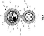
- Figure 1 is a cross-sectional view of a cable assembly according to an embodiment of the present invention.
- the cable assembly is generally designed by reference number 100.
- Cable assembly 100 is an optical and electrical cable assembly and it comprises an optical core 21 and an electrical core 11. More specifically, cable assembly 100 is adapted for use as an aerial drop cable in FTTH applications.
- the cable assembly 100 comprises a common figure-8 outer jacket 30 having a first lobe 10 and a second lobe 20.
- First lobe 10 of the common figure-8 outer jacket 30 surrounds a first inner sheath 15 housing an electric core 11.
- the first inner sheath 15 is an extruded sheath made, for instance, of polyethylene, such as low density polyethylene (LDPE) or medium density polyethylene (MDPE) suitable to fulfil the requirement of BS EN 50290-2-23-2013.
- LDPE low density polyethylene
- MDPE medium density polyethylene
- the first inner sheath 15 can have a thickness of from 0.3 mm to 0.6 mm. In one preferred embodiment, the thickness of the first inner sheath 15 is 0.4 mm.
- the outer diameter of the first inner sheath 15 is of from 4.0 to 6.0 mm.
- the outer diameter of the first inner sheath 15 is of about 5.0 mm.
- the first inner sheath 15 houses an electric core 11 comprising three power conductors 12 and one copper pair 13.
- each of the power conductors 12 comprises an electrically conductive core and an electrically insulating layer therearound.
- the electrically conductive cores can be made of copper or aluminium, preferably of copper.
- the power conductors 12 are, typically, for low voltage application, i.e. suitable for transport current up to a voltage of less than about 1 kV.
- the power conductors can be, for example, solid annealed bare copper of 0.5/0.9 mm fulfilling the requirement of the standard IEC 60228-2004 3 rd ed.
- Copper pair 13 or quad is suitable for data transport.
- Each copper pair 13 or quad comprises a twisted pair or quad of telecommunication conductors 13a, each comprising a copper wire covered by an electrical insulation layer made of polymeric material, for example polyethylene.
- the copper pairs or quads are stranded together and optionally wrapped by a tape 16 made of polymeric material, for example polypropylene.
- the power conductors and/or copper pairs can be wrapped together by a polymeric tape, for example of polyester.
- a polymeric tape for example of polyester.
- Such polymeric tape is in radially inner position with respect to the first inner sheath.
- the first inner sheath 15 further houses members 14.
- the strength members 14 can be made of a non-metallic material or of an electrically non-conductive metallic material.
- An example of suitable non-metallic material is glass reinforced polymer.
- An example of suitable electrically non-conductive metallic material is steel or metal coated steel. Strength members in non-conductive metallic material are preferred, optionally coated with a polymeric material.
- the strength members 14 are provided in positions which are substantially radially opposed one to the other.
- the cable will exhibit a reduced and more uniform flexibility. Also, as the strength members are not embedded in the cable jacket they are more easily accessible and this is important especially when the strength members are made of metallic material as they have to be earthed in case of short circuit test.
- an aerial cable comprises metallic strength members such as steel strength members
- the cable could be requested to withstand a short circuit test, for example at 15 kV, where the metal strength members are earthed and the voltage is applied to the outside of the cable.
- a short circuit test for example at 15 kV
- dielectric polymer such as polyethylene
- the metallic strength members are provided within the first inner extruded sheath there is more than 0.75 mm radial of dielectric polymer around the strength members. Accordingly, the radial thickness of the common figure-8 outer jacket does not have to be as high as in known cables thus making it easier to strip the jacket from the cable for releasing the electric and/or telecommunication self-standing cable.
- strength members 14 may comprise one element of 3x0.41 mm brass coated steel strings, the element being coated with polyvinylchloride (PVC) to an overall diameter of 1.4 mm.
- strength members 14 may comprise three elements of 3x0.25 mm brass coated steel strings; the element being coated with PVC to an overall diameter of 1.0 mm.
- the common figure-8 outer jacket is removed and the first inner extruded sheath housing the electric core and the strength member/s becomes a self-standing electric and/or telecommunication cable.
- Second lobe 20 of the common figure-8 outer jacket 30 surrounds a second inner extruded sheath 25 housing an optical core 21.
- Optical core 21 comprises one or more optical fibers 22.
- the second inner extruded sheath 25 is made, for instance, of polyethylene, such as low density polyethylene (LDPE) or medium density polyethylene (MDPE) suitable to fulfil the requirement of standard BS EN 50290-2-23-2013.
- the second inner sheath 25 can have a thickness of from 0.2 mm to 0.8 mm. In one preferred embodiment, the thickness of the second inner sheath 25 is 0.4 mm.
- the optical core (and the resulting self-standing optical cable) may comprise up to 24 optical fibers in loose configuration; 2, 4, 6, 8 or 12 optical fibers in EPFU (Enhanced Performance Fibre Unit) format for blown fibre applications; up to four tubes (modules or micromodules) each in turn containing 12 optical fibers; or up to two optical fibers each coated by yarns (for example, aramid yarns) surrounded by a polymeric protective jacket (patchcord format).
- EPFU Enhanced Performance Fibre Unit
- a water blocking material can be provided into radial internal position with respect to the second inner sheath 25 to prevent water or moisture to damage the optical fibers 22.
- the water blocking material can be in form of yarn, tape or gel.
- the outer diameter of the second inner sheath 25 can be of from 2.0 to 3.0 mm.
- the outer diameter of the second inner sheath 25 is 2.2 mm.
- the common figure-8 outer jacket is removed and the second inner extruded sheath housing the optical core becomes a self-standing optical cable.
- the cable assembly 100 of the present invention comprises an outer common jacket 30.
- Outer common sheath 30 is provided radially outer the first inner sheath 15 and radially outer the second inner sheath 25.
- the outer common jacket 30 is substantially in a shape of "8" with a web 33 connecting a first lobe 10 which is radially external to the first inner sheath 15 and a second lobe 20 which is radially external to the second inner sheath 25.
- Outer common jacket 30 may comprise, or may essentially consist of, a polyethylene.
- outer common jacket 30 comprises, or essentially consists of, high density polyethylene (HDPE), preferably having a flexural modulus of 800-1400 MPa and a tensile Strain at Break (50 mm/min) of 900-1.500 %.
- HDPE high density polyethylene
- the HDPE polymer suitable for the outer common jacket of the present cable advantageously have an Environmental Stress Crack Resistance at 50 °C greater than 5000 h measured according to IEC 60811-4-1:2004.
- Outer common jacket 30 can have a thickness of from 0.5 mm to 1.0 mm.
- outer common jacket 30 has a thickness of 0.9-1.0 mm.
- the outer common jacket should adhere to the underlying first and second inner sheaths in a sufficient manner to ensure a suitable mechanical congruence during operation, but should also be readily detachable from said sheaths to free the self-standing cables.
- the outer common jacket can be extruded over the first and second inner sheaths when the latters are already cooled down and/or carrying the extrusion under controlled temperature and pressure conditions known to the skilled ones.
- first and second inner sheaths can be spread with an antifriction agent like chalk before the outer common jacket extrusion.
- Web 33 can be 1.0 to 2.0 mm long.
- At least one ripcord 32 can be embedded within the thickness of the outer common jacket 30.
- two ripcords 32 are provided.
- the ripcords 32 are preferably arranged substantially opposed one to the other along the plane A-A'.
- the ripcords 32 are made of aramid, nylon or the like.
- the cable assembly of the present invention can have small dimensions.
- the assembly 100 can have a maximum radial width on the plane B-B' of 6.8 mm (across the first lobe 10; the width across the second lobe 20 can be of 4.0 mm) and a maximum radial width on the plane A-A' 12.3 mm.
Landscapes
- Physics & Mathematics (AREA)
- General Physics & Mathematics (AREA)
- Optics & Photonics (AREA)
- Insulated Conductors (AREA)
- Communication Cables (AREA)
Claims (13)
- Eine Kabelanordnung (100), die Folgendes umfasst:Einen gemeinsamen 8-förmigen Außenmantel (30) mit einem ersten Bauch (10) und einem zweiten Bauch (20), einem elektrischen Kern (11), zwei Festigkeitselemente (14) und einem ersten extrudierten Innenmantel (15), der den elektrischen Kern (11) und die Festigkeitselemente (14) umgibt, wobei der erste Bauch (10) den ersten extrudierten Innenmantel (15) umgibt, wobei der erste extrudierte Innenmantel (15) die Festigkeitselemente (14) ringförmig umgibt und wobei die Festigkeitselemente (14) parallel zur Längsachse des ersten Bauchs (10) angeordnet sind, undeinen optischen Kern (21) und einen zweiten extrudierten Innenmantel (25), der den optischen Kern (21) aufnimmt, wobei der zweite Bauch (20) den zweiten extrudierten Innenmantel (25) umgibt, wobei der gemeinsame 8-förmige Außenmantel (30) an dem ersten extrudierten Innenmantel (15) und an dem zweiten extrudierten Innenmantel (25) haftet und so konfiguriert ist, dass er leicht von dem ersten und dem zweiten extrudierten Innenmantel (15, 25) zu lösen, um ein selbststehendes elektrisches Kabel freizugeben, das durch den ersten extrudierten Innenmantel (15) und das, was der erste extrudierte Innenmantel (15) aufnimmt, gebildet wird, und ein selbststehendes optisches Kabel, das durch den zweiten extrudierten Innenmantel (25) und das, was der zweite extrudierte Innenmantel (25) aufnimmt, gebildet wird.
- Kabelanordnung (100) nach Anspruch 1, wobei die Festigkeitselemente (14) aus einem nichtmetallischen Material oder aus einem elektrisch nicht leitenden metallischen Material bestehen.
- Kabelanordnung (100) nach Anspruch 1, wobei der gemeinsame 8-förmige Außenmantel (30) eine Reißleine (32) einbettet.
- Kabelanordnung (100) nach Anspruch 3, wobei der gemeinsame 8-förmige Außenmantel (30) eine Reißleine (32) für jeden ersten und zweiten Bauch (10, 20) einbettet.
- Kabelanordnung (100) nach Anspruch 4, bei der die Reißleine (32) des ersten Bauchs (10) und die Reißleine (32) des zweiten Bauchs (20) an diametral gegenüberliegenden Positionen in dem gemeinsamen 8-förmigen Außenmantel (30) eingebettet sind.
- Kabelanordnung (100) nach Anspruch 1, wobei der erste extrudierte Innenmantel (15) und der zweite extrudierte Innenmantel (25) eine Dicke von mindestens 0,2 mm aufweisen.
- Kabelanordnung (100) nach Anspruch 1, wobei der erste extrudierte Innenmantel (15) eine Dicke von 0,3 mm bis 0,6 mm aufweist.
- Kabelbaugruppe (100) nach Anspruch 1, wobei der gemeinsame 8-förmige Außenmantel (30) einen Steg (33) umfasst, der den ersten Bauch (10) und den zweiten Bauch (20) verbindet.
- Kabelbaugruppe (100) nach Anspruch 1, wobei der elektrische Kern (11) einen Stromleiter (12), einen Telekommunikationsleiter (13) oder beides umfasst.
- Kabelanordnung (100) nach Anspruch 1, wobei der gemeinsame 8-förmige Außenmantel (30) eine Dicke von 0,5 mm bis 1,0 mm aufweist.
- Kabelbaugruppe (100) nach Anspruch 1, wobei die beiden Festigkeitselemente (14) an diametral gegenüberliegenden Positionen angeordnet sind.
- Kabelanordnung (100) nach Anspruch 1, wobei der optische Kern (21) eine Vielzahl von optischen Fasern umfasst.
- Kabelanordnung (100) nach Anspruch 12, wobei der optische Kern (21) ferner dielektrische Elemente zum Schutz der optischen Fasern umfasst.
Priority Applications (1)
| Application Number | Priority Date | Filing Date | Title |
|---|---|---|---|
| PL15725602.5T PL3304155T3 (pl) | 2015-05-27 | 2015-05-27 | Zespół napowietrznego kabla elektrycznego i optycznego |
Applications Claiming Priority (1)
| Application Number | Priority Date | Filing Date | Title |
|---|---|---|---|
| PCT/EP2015/061645 WO2016188570A1 (en) | 2015-05-27 | 2015-05-27 | Aerial optical and electric cable assembly |
Publications (2)
| Publication Number | Publication Date |
|---|---|
| EP3304155A1 EP3304155A1 (de) | 2018-04-11 |
| EP3304155B1 true EP3304155B1 (de) | 2022-07-20 |
Family
ID=53274531
Family Applications (1)
| Application Number | Title | Priority Date | Filing Date |
|---|---|---|---|
| EP15725602.5A Active EP3304155B1 (de) | 2015-05-27 | 2015-05-27 | Anordnung eines optischen und elektrischen luftkabels |
Country Status (8)
| Country | Link |
|---|---|
| US (1) | US10416402B2 (de) |
| EP (1) | EP3304155B1 (de) |
| CN (1) | CN107667307B (de) |
| AU (1) | AU2015396467B2 (de) |
| CA (1) | CA2986474C (de) |
| ES (1) | ES2928470T3 (de) |
| PL (1) | PL3304155T3 (de) |
| WO (1) | WO2016188570A1 (de) |
Families Citing this family (1)
| Publication number | Priority date | Publication date | Assignee | Title |
|---|---|---|---|---|
| US20220223318A1 (en) * | 2021-01-12 | 2022-07-14 | Superior Essex International LP | Twisted pair communication cables with integrating pulling elements |
Citations (1)
| Publication number | Priority date | Publication date | Assignee | Title |
|---|---|---|---|---|
| US6356690B1 (en) * | 1999-10-20 | 2002-03-12 | Corning Cable Systems Llc | Self-supporting fiber optic cable |
Family Cites Families (25)
| Publication number | Priority date | Publication date | Assignee | Title |
|---|---|---|---|---|
| US4052911A (en) * | 1973-05-18 | 1977-10-11 | Incom International Inc. | Cable core conduit |
| JPS50156944A (de) * | 1974-06-07 | 1975-12-18 | ||
| GB2103822B (en) * | 1981-07-23 | 1985-08-21 | Standard Telephones Cables Ltd | Flame retardant plastics sheathed optical and/or electrical cables |
| US4763983A (en) * | 1986-12-31 | 1988-08-16 | Sumitomo Electric Research Triangle, Inc. | Optical transmission cable with messenger |
| GB8905738D0 (en) * | 1989-03-14 | 1989-04-26 | Bicc Plc | Composite aerial cable |
| US5189718A (en) * | 1991-04-02 | 1993-02-23 | Siecor Corporation | Composite cable containing light waveguides and electrical conductors |
| US5636305A (en) * | 1992-09-30 | 1997-06-03 | Siecor Corporation | Magnetic locatable figure-8 cable |
| US5469523A (en) * | 1994-06-10 | 1995-11-21 | Commscope, Inc. | Composite fiber optic and electrical cable and associated fabrication method |
| US5740295A (en) | 1994-11-02 | 1998-04-14 | Lucent Technologies Inc. | Low fiber count optical cable |
| US5777260A (en) | 1995-03-14 | 1998-07-07 | Siemens Aktiengesellschaft | Coaxial cable additionally having at least one light waveguide |
| US6169834B1 (en) * | 1998-05-13 | 2001-01-02 | Alcatel | Slotted composite cable having a cable housing with a tubular opening for copper pairs and a slot for an optical fiber |
| US6363192B1 (en) * | 1998-12-23 | 2002-03-26 | Corning Cable Systems Llc | Composite cable units |
| US6236789B1 (en) * | 1999-12-22 | 2001-05-22 | Pirelli Cables And Systems Llc | Composite cable for access networks |
| US6546175B1 (en) * | 2000-05-26 | 2003-04-08 | Corning Cable Systems Llc | Self-supporting fiber optic cable |
| CA2467513C (en) * | 2001-11-19 | 2011-09-27 | Pirelli General Plc | Optical fibre drop cables |
| US6928217B2 (en) * | 2003-07-18 | 2005-08-09 | Corning Cable Systems Llc | Fiber optic cable having a strength member |
| ES2359062T3 (es) * | 2003-08-28 | 2011-05-18 | Prysmian S.P.A. | Cable óptico y unidad óptica comprendida en el mismo. |
| FR2904140B1 (fr) * | 2006-07-19 | 2008-10-17 | Pomagalski Sa | Cable multiconducteurs a double porteur pour une ligne de securite d'equipements sur les pylones et de communication en gare d'une installation de transport teleportee. |
| US9170388B2 (en) * | 2011-09-30 | 2015-10-27 | Corning Cable Systems Llc | Fiber optic ribbon cable having enhanced ribbon stack coupling and methods thereof |
| US9679681B2 (en) * | 2012-04-27 | 2017-06-13 | Corning Optical Communications LLC | Hybrid cable including fiber-optic and electrical-conductor elements |
| CN202816448U (zh) * | 2012-09-13 | 2013-03-20 | 广东雄力电缆有限公司 | 一种抗拉软电缆 |
| CN203085218U (zh) * | 2013-01-10 | 2013-07-24 | 安徽华津电缆集团有限公司 | 硅橡胶控制电缆 |
| US9557505B2 (en) * | 2013-03-18 | 2017-01-31 | Commscope Technologies Llc | Power and optical fiber interface |
| CN203706703U (zh) * | 2013-12-25 | 2014-07-09 | 特变电工(德阳)电缆股份有限公司 | 一种向飞机输电用电缆 |
| CN104021878A (zh) * | 2014-06-05 | 2014-09-03 | 苏州胜信光电科技有限公司 | 一种信息入户复合缆 |
-
2015
- 2015-05-27 CN CN201580080265.XA patent/CN107667307B/zh active Active
- 2015-05-27 ES ES15725602T patent/ES2928470T3/es active Active
- 2015-05-27 PL PL15725602.5T patent/PL3304155T3/pl unknown
- 2015-05-27 AU AU2015396467A patent/AU2015396467B2/en active Active
- 2015-05-27 WO PCT/EP2015/061645 patent/WO2016188570A1/en not_active Ceased
- 2015-05-27 EP EP15725602.5A patent/EP3304155B1/de active Active
- 2015-05-27 US US15/576,342 patent/US10416402B2/en active Active
- 2015-05-27 CA CA2986474A patent/CA2986474C/en active Active
Patent Citations (1)
| Publication number | Priority date | Publication date | Assignee | Title |
|---|---|---|---|---|
| US6356690B1 (en) * | 1999-10-20 | 2002-03-12 | Corning Cable Systems Llc | Self-supporting fiber optic cable |
Also Published As
| Publication number | Publication date |
|---|---|
| WO2016188570A1 (en) | 2016-12-01 |
| US10416402B2 (en) | 2019-09-17 |
| CN107667307A (zh) | 2018-02-06 |
| US20180172936A1 (en) | 2018-06-21 |
| CN107667307B (zh) | 2021-10-08 |
| CA2986474A1 (en) | 2016-12-01 |
| CA2986474C (en) | 2022-11-01 |
| EP3304155A1 (de) | 2018-04-11 |
| AU2015396467B2 (en) | 2021-03-25 |
| ES2928470T3 (es) | 2022-11-18 |
| PL3304155T3 (pl) | 2022-12-19 |
| AU2015396467A1 (en) | 2017-12-14 |
Similar Documents
| Publication | Publication Date | Title |
|---|---|---|
| KR101261320B1 (ko) | 광전 복합 케이블 | |
| US7272281B2 (en) | Powered fiber cable | |
| US7218821B2 (en) | Optical fiber cables | |
| AU2016238858B2 (en) | Low- fire hazard optical fiber drop cable | |
| US6370303B1 (en) | Optical fiber cable with support member for indoor and outdoor use | |
| US20050123254A1 (en) | Optical fiber composite electrical power cable | |
| US5822484A (en) | Lightweight optical groundwire | |
| WO1997030369A1 (en) | Fiber optic ground wire cable | |
| CN102037521A (zh) | 金属护套的电缆组件 | |
| US11714248B2 (en) | High density bundled optical fiber cable with preconnectorized drop points | |
| US20190113703A1 (en) | Fiber Optic Drop Cable | |
| EP3304155B1 (de) | Anordnung eines optischen und elektrischen luftkabels | |
| EP2482110B1 (de) | Optische Anordnung und optisches Kabel dafür | |
| CN107004467A (zh) | 自支撑高架通信/电力线缆 | |
| US11508496B2 (en) | Opto-electric cable | |
| EP1293992A2 (de) | Opto-elektrisches Hybridkabel | |
| US20250385504A1 (en) | Conductor splice connectors for use with hybrid conductors |
Legal Events
| Date | Code | Title | Description |
|---|---|---|---|
| STAA | Information on the status of an ep patent application or granted ep patent |
Free format text: STATUS: THE INTERNATIONAL PUBLICATION HAS BEEN MADE |
|
| PUAI | Public reference made under article 153(3) epc to a published international application that has entered the european phase |
Free format text: ORIGINAL CODE: 0009012 |
|
| STAA | Information on the status of an ep patent application or granted ep patent |
Free format text: STATUS: REQUEST FOR EXAMINATION WAS MADE |
|
| 17P | Request for examination filed |
Effective date: 20171129 |
|
| AK | Designated contracting states |
Kind code of ref document: A1 Designated state(s): AL AT BE BG CH CY CZ DE DK EE ES FI FR GB GR HR HU IE IS IT LI LT LU LV MC MK MT NL NO PL PT RO RS SE SI SK SM TR |
|
| AX | Request for extension of the european patent |
Extension state: BA ME |
|
| DAV | Request for validation of the european patent (deleted) | ||
| DAX | Request for extension of the european patent (deleted) | ||
| STAA | Information on the status of an ep patent application or granted ep patent |
Free format text: STATUS: EXAMINATION IS IN PROGRESS |
|
| 17Q | First examination report despatched |
Effective date: 20201007 |
|
| GRAP | Despatch of communication of intention to grant a patent |
Free format text: ORIGINAL CODE: EPIDOSNIGR1 |
|
| STAA | Information on the status of an ep patent application or granted ep patent |
Free format text: STATUS: GRANT OF PATENT IS INTENDED |
|
| RIC1 | Information provided on ipc code assigned before grant |
Ipc: H01B 11/00 20060101ALI20220202BHEP Ipc: G02B 6/44 20060101AFI20220202BHEP |
|
| INTG | Intention to grant announced |
Effective date: 20220218 |
|
| GRAS | Grant fee paid |
Free format text: ORIGINAL CODE: EPIDOSNIGR3 |
|
| GRAA | (expected) grant |
Free format text: ORIGINAL CODE: 0009210 |
|
| STAA | Information on the status of an ep patent application or granted ep patent |
Free format text: STATUS: THE PATENT HAS BEEN GRANTED |
|
| AK | Designated contracting states |
Kind code of ref document: B1 Designated state(s): AL AT BE BG CH CY CZ DE DK EE ES FI FR GB GR HR HU IE IS IT LI LT LU LV MC MK MT NL NO PL PT RO RS SE SI SK SM TR |
|
| REG | Reference to a national code |
Ref country code: GB Ref legal event code: FG4D |
|
| REG | Reference to a national code |
Ref country code: CH Ref legal event code: EP |
|
| REG | Reference to a national code |
Ref country code: DE Ref legal event code: R096 Ref document number: 602015079922 Country of ref document: DE |
|
| REG | Reference to a national code |
Ref country code: AT Ref legal event code: REF Ref document number: 1505892 Country of ref document: AT Kind code of ref document: T Effective date: 20220815 |
|
| REG | Reference to a national code |
Ref country code: IE Ref legal event code: FG4D |
|
| REG | Reference to a national code |
Ref country code: NL Ref legal event code: FP |
|
| REG | Reference to a national code |
Ref country code: LT Ref legal event code: MG9D |
|
| REG | Reference to a national code |
Ref country code: ES Ref legal event code: FG2A Ref document number: 2928470 Country of ref document: ES Kind code of ref document: T3 Effective date: 20221118 |
|
| PG25 | Lapsed in a contracting state [announced via postgrant information from national office to epo] |
Ref country code: SE Free format text: LAPSE BECAUSE OF FAILURE TO SUBMIT A TRANSLATION OF THE DESCRIPTION OR TO PAY THE FEE WITHIN THE PRESCRIBED TIME-LIMIT Effective date: 20220720 Ref country code: RS Free format text: LAPSE BECAUSE OF FAILURE TO SUBMIT A TRANSLATION OF THE DESCRIPTION OR TO PAY THE FEE WITHIN THE PRESCRIBED TIME-LIMIT Effective date: 20220720 Ref country code: PT Free format text: LAPSE BECAUSE OF FAILURE TO SUBMIT A TRANSLATION OF THE DESCRIPTION OR TO PAY THE FEE WITHIN THE PRESCRIBED TIME-LIMIT Effective date: 20221121 Ref country code: NO Free format text: LAPSE BECAUSE OF FAILURE TO SUBMIT A TRANSLATION OF THE DESCRIPTION OR TO PAY THE FEE WITHIN THE PRESCRIBED TIME-LIMIT Effective date: 20221020 Ref country code: LV Free format text: LAPSE BECAUSE OF FAILURE TO SUBMIT A TRANSLATION OF THE DESCRIPTION OR TO PAY THE FEE WITHIN THE PRESCRIBED TIME-LIMIT Effective date: 20220720 Ref country code: LT Free format text: LAPSE BECAUSE OF FAILURE TO SUBMIT A TRANSLATION OF THE DESCRIPTION OR TO PAY THE FEE WITHIN THE PRESCRIBED TIME-LIMIT Effective date: 20220720 Ref country code: FI Free format text: LAPSE BECAUSE OF FAILURE TO SUBMIT A TRANSLATION OF THE DESCRIPTION OR TO PAY THE FEE WITHIN THE PRESCRIBED TIME-LIMIT Effective date: 20220720 |
|
| REG | Reference to a national code |
Ref country code: AT Ref legal event code: MK05 Ref document number: 1505892 Country of ref document: AT Kind code of ref document: T Effective date: 20220720 |
|
| PG25 | Lapsed in a contracting state [announced via postgrant information from national office to epo] |
Ref country code: IS Free format text: LAPSE BECAUSE OF FAILURE TO SUBMIT A TRANSLATION OF THE DESCRIPTION OR TO PAY THE FEE WITHIN THE PRESCRIBED TIME-LIMIT Effective date: 20221120 Ref country code: HR Free format text: LAPSE BECAUSE OF FAILURE TO SUBMIT A TRANSLATION OF THE DESCRIPTION OR TO PAY THE FEE WITHIN THE PRESCRIBED TIME-LIMIT Effective date: 20220720 Ref country code: GR Free format text: LAPSE BECAUSE OF FAILURE TO SUBMIT A TRANSLATION OF THE DESCRIPTION OR TO PAY THE FEE WITHIN THE PRESCRIBED TIME-LIMIT Effective date: 20221021 |
|
| REG | Reference to a national code |
Ref country code: DE Ref legal event code: R097 Ref document number: 602015079922 Country of ref document: DE |
|
| PG25 | Lapsed in a contracting state [announced via postgrant information from national office to epo] |
Ref country code: SM Free format text: LAPSE BECAUSE OF FAILURE TO SUBMIT A TRANSLATION OF THE DESCRIPTION OR TO PAY THE FEE WITHIN THE PRESCRIBED TIME-LIMIT Effective date: 20220720 Ref country code: RO Free format text: LAPSE BECAUSE OF FAILURE TO SUBMIT A TRANSLATION OF THE DESCRIPTION OR TO PAY THE FEE WITHIN THE PRESCRIBED TIME-LIMIT Effective date: 20220720 Ref country code: DK Free format text: LAPSE BECAUSE OF FAILURE TO SUBMIT A TRANSLATION OF THE DESCRIPTION OR TO PAY THE FEE WITHIN THE PRESCRIBED TIME-LIMIT Effective date: 20220720 Ref country code: CZ Free format text: LAPSE BECAUSE OF FAILURE TO SUBMIT A TRANSLATION OF THE DESCRIPTION OR TO PAY THE FEE WITHIN THE PRESCRIBED TIME-LIMIT Effective date: 20220720 Ref country code: AT Free format text: LAPSE BECAUSE OF FAILURE TO SUBMIT A TRANSLATION OF THE DESCRIPTION OR TO PAY THE FEE WITHIN THE PRESCRIBED TIME-LIMIT Effective date: 20220720 |
|
| PLBE | No opposition filed within time limit |
Free format text: ORIGINAL CODE: 0009261 |
|
| STAA | Information on the status of an ep patent application or granted ep patent |
Free format text: STATUS: NO OPPOSITION FILED WITHIN TIME LIMIT |
|
| PG25 | Lapsed in a contracting state [announced via postgrant information from national office to epo] |
Ref country code: SK Free format text: LAPSE BECAUSE OF FAILURE TO SUBMIT A TRANSLATION OF THE DESCRIPTION OR TO PAY THE FEE WITHIN THE PRESCRIBED TIME-LIMIT Effective date: 20220720 Ref country code: EE Free format text: LAPSE BECAUSE OF FAILURE TO SUBMIT A TRANSLATION OF THE DESCRIPTION OR TO PAY THE FEE WITHIN THE PRESCRIBED TIME-LIMIT Effective date: 20220720 |
|
| 26N | No opposition filed |
Effective date: 20230421 |
|
| PG25 | Lapsed in a contracting state [announced via postgrant information from national office to epo] |
Ref country code: AL Free format text: LAPSE BECAUSE OF FAILURE TO SUBMIT A TRANSLATION OF THE DESCRIPTION OR TO PAY THE FEE WITHIN THE PRESCRIBED TIME-LIMIT Effective date: 20220720 |
|
| PG25 | Lapsed in a contracting state [announced via postgrant information from national office to epo] |
Ref country code: SI Free format text: LAPSE BECAUSE OF FAILURE TO SUBMIT A TRANSLATION OF THE DESCRIPTION OR TO PAY THE FEE WITHIN THE PRESCRIBED TIME-LIMIT Effective date: 20220720 |
|
| REG | Reference to a national code |
Ref country code: CH Ref legal event code: PL |
|
| PG25 | Lapsed in a contracting state [announced via postgrant information from national office to epo] |
Ref country code: MC Free format text: LAPSE BECAUSE OF FAILURE TO SUBMIT A TRANSLATION OF THE DESCRIPTION OR TO PAY THE FEE WITHIN THE PRESCRIBED TIME-LIMIT Effective date: 20220720 |
|
| REG | Reference to a national code |
Ref country code: BE Ref legal event code: MM Effective date: 20230531 |
|
| PG25 | Lapsed in a contracting state [announced via postgrant information from national office to epo] |
Ref country code: MC Free format text: LAPSE BECAUSE OF FAILURE TO SUBMIT A TRANSLATION OF THE DESCRIPTION OR TO PAY THE FEE WITHIN THE PRESCRIBED TIME-LIMIT Effective date: 20220720 Ref country code: LU Free format text: LAPSE BECAUSE OF NON-PAYMENT OF DUE FEES Effective date: 20230527 Ref country code: LI Free format text: LAPSE BECAUSE OF NON-PAYMENT OF DUE FEES Effective date: 20230531 Ref country code: CH Free format text: LAPSE BECAUSE OF NON-PAYMENT OF DUE FEES Effective date: 20230531 |
|
| REG | Reference to a national code |
Ref country code: IE Ref legal event code: MM4A |
|
| PG25 | Lapsed in a contracting state [announced via postgrant information from national office to epo] |
Ref country code: IE Free format text: LAPSE BECAUSE OF NON-PAYMENT OF DUE FEES Effective date: 20230527 |
|
| PG25 | Lapsed in a contracting state [announced via postgrant information from national office to epo] |
Ref country code: IE Free format text: LAPSE BECAUSE OF NON-PAYMENT OF DUE FEES Effective date: 20230527 |
|
| PG25 | Lapsed in a contracting state [announced via postgrant information from national office to epo] |
Ref country code: BE Free format text: LAPSE BECAUSE OF NON-PAYMENT OF DUE FEES Effective date: 20230531 |
|
| PG25 | Lapsed in a contracting state [announced via postgrant information from national office to epo] |
Ref country code: BG Free format text: LAPSE BECAUSE OF FAILURE TO SUBMIT A TRANSLATION OF THE DESCRIPTION OR TO PAY THE FEE WITHIN THE PRESCRIBED TIME-LIMIT Effective date: 20220720 |
|
| PG25 | Lapsed in a contracting state [announced via postgrant information from national office to epo] |
Ref country code: BG Free format text: LAPSE BECAUSE OF FAILURE TO SUBMIT A TRANSLATION OF THE DESCRIPTION OR TO PAY THE FEE WITHIN THE PRESCRIBED TIME-LIMIT Effective date: 20220720 |
|
| PGFP | Annual fee paid to national office [announced via postgrant information from national office to epo] |
Ref country code: NL Payment date: 20250526 Year of fee payment: 11 |
|
| PGFP | Annual fee paid to national office [announced via postgrant information from national office to epo] |
Ref country code: DE Payment date: 20250529 Year of fee payment: 11 Ref country code: PL Payment date: 20250508 Year of fee payment: 11 |
|
| PGFP | Annual fee paid to national office [announced via postgrant information from national office to epo] |
Ref country code: GB Payment date: 20250527 Year of fee payment: 11 Ref country code: ES Payment date: 20250602 Year of fee payment: 11 |
|
| PGFP | Annual fee paid to national office [announced via postgrant information from national office to epo] |
Ref country code: IT Payment date: 20250521 Year of fee payment: 11 |
|
| PGFP | Annual fee paid to national office [announced via postgrant information from national office to epo] |
Ref country code: FR Payment date: 20250526 Year of fee payment: 11 |
|
| PG25 | Lapsed in a contracting state [announced via postgrant information from national office to epo] |
Ref country code: CY Free format text: LAPSE BECAUSE OF FAILURE TO SUBMIT A TRANSLATION OF THE DESCRIPTION OR TO PAY THE FEE WITHIN THE PRESCRIBED TIME-LIMIT; INVALID AB INITIO Effective date: 20150527 |
|
| PG25 | Lapsed in a contracting state [announced via postgrant information from national office to epo] |
Ref country code: HU Free format text: LAPSE BECAUSE OF FAILURE TO SUBMIT A TRANSLATION OF THE DESCRIPTION OR TO PAY THE FEE WITHIN THE PRESCRIBED TIME-LIMIT; INVALID AB INITIO Effective date: 20150527 |
|
| PG25 | Lapsed in a contracting state [announced via postgrant information from national office to epo] |
Ref country code: TR Free format text: LAPSE BECAUSE OF FAILURE TO SUBMIT A TRANSLATION OF THE DESCRIPTION OR TO PAY THE FEE WITHIN THE PRESCRIBED TIME-LIMIT Effective date: 20220720 |