EP3304729B1 - Vorrichtung eines universalanschlusskastens für module - Google Patents
Vorrichtung eines universalanschlusskastens für module Download PDFInfo
- Publication number
- EP3304729B1 EP3304729B1 EP16804436.0A EP16804436A EP3304729B1 EP 3304729 B1 EP3304729 B1 EP 3304729B1 EP 16804436 A EP16804436 A EP 16804436A EP 3304729 B1 EP3304729 B1 EP 3304729B1
- Authority
- EP
- European Patent Office
- Prior art keywords
- block
- assembly
- blade
- sub
- solar module
- Prior art date
- Legal status (The legal status is an assumption and is not a legal conclusion. Google has not performed a legal analysis and makes no representation as to the accuracy of the status listed.)
- Active
Links
Images







Classifications
-
- H—ELECTRICITY
- H02—GENERATION; CONVERSION OR DISTRIBUTION OF ELECTRIC POWER
- H02S—GENERATION OF ELECTRIC POWER BY CONVERSION OF INFRARED RADIATION, VISIBLE LIGHT OR ULTRAVIOLET LIGHT, e.g. USING PHOTOVOLTAIC [PV] MODULES
- H02S40/00—Components or accessories in combination with PV modules, not provided for in groups H02S10/00 - H02S30/00
- H02S40/30—Electrical components
- H02S40/34—Electrical components comprising specially adapted electrical connection means to be structurally associated with the PV module, e.g. junction boxes
-
- H—ELECTRICITY
- H02—GENERATION; CONVERSION OR DISTRIBUTION OF ELECTRIC POWER
- H02S—GENERATION OF ELECTRIC POWER BY CONVERSION OF INFRARED RADIATION, VISIBLE LIGHT OR ULTRAVIOLET LIGHT, e.g. USING PHOTOVOLTAIC [PV] MODULES
- H02S40/00—Components or accessories in combination with PV modules, not provided for in groups H02S10/00 - H02S30/00
- H02S40/30—Electrical components
- H02S40/32—Electrical components comprising DC/AC inverter means associated with the PV module itself, e.g. AC modules
-
- Y—GENERAL TAGGING OF NEW TECHNOLOGICAL DEVELOPMENTS; GENERAL TAGGING OF CROSS-SECTIONAL TECHNOLOGIES SPANNING OVER SEVERAL SECTIONS OF THE IPC; TECHNICAL SUBJECTS COVERED BY FORMER USPC CROSS-REFERENCE ART COLLECTIONS [XRACs] AND DIGESTS
- Y02—TECHNOLOGIES OR APPLICATIONS FOR MITIGATION OR ADAPTATION AGAINST CLIMATE CHANGE
- Y02E—REDUCTION OF GREENHOUSE GAS [GHG] EMISSIONS, RELATED TO ENERGY GENERATION, TRANSMISSION OR DISTRIBUTION
- Y02E10/00—Energy generation through renewable energy sources
- Y02E10/50—Photovoltaic [PV] energy
Definitions
- the present invention relates generally to solar technologies and, more particularly, to a solar junction box assembly for providing electronics to solar panels.
- a solar module or a photovoltaic (PV) module is a packaged and connected assembly with a matrix of solar cells. Each solar module is rated by its direct current (DC) output power under a set of test conditions.
- DC direct current
- One industrial leading company designing and manufacturing solar cells and solar modules is JA Solar, www.jasolar.com.
- the solar box includes a connection box operatively connected to an optional extension module.
- the optional extension module Inserted between a junction box and an expansion module, the optional extension module has an electronic circuit for controlling a connected solar panel, and transmits power from the junction box to the expansion module.
- Embodiments of the present disclosure are directed to a universal junction box for solar modules that comprises multiple sub-assemblies with a replaceable diode block and an open-IP plug sub-assembly.
- the universal junction box includes a first sub-assembly (junction box platform), a second sub-assembly (a replaceable diode block), and a third sub-assembly (an open sub-assembly or plug sub-assembly). If the electronics in the diode block become defective, a new replaceable diode block can be used to substitute into the defective diode block without having to replace the entire junction box.
- the open-IP plug sub-assembly provides the flexibility to couple a variety of cable sub-assemblies or IMEs to the universal junction box, as long as a particular selected cable sub-assembly fits with the dimension of the open-IP plug sub-assembly.
- a universal solar module box mounted on a solar module comprises (i) a junction box platform having a base plate, a blade block, and a cover, the blade block having a first blade and a second blade; (ii) a modular diode block electrically and mechanically coupleable to the junction box platform via the blade block.
- the modular diode block has a first connector and a second connector. The first blade of the blade block extends through the base plate and protruding through the first connector of the modular diode block for establishing an electrical connection between the first blade of the blade block and the first connector of the modular diode block.
- the second blade of the blade block extends through the base plate and protruding through the second connector of the modular diode block for establishing an electrical connection between the second blade of the blade block and the second connector of the modular diode block.
- the universal solar module box further includes (iii) a plug sub-assembly that has a plug block and a cable block, attachable to the junction box platform and the modular diode block.
- the plug sub-assembly provides a protective covering to weatherize the diode block, the blade block, and the cable block.
- the cable block is attachable mechanically to the plug block.
- the cable block secures mechanically and electrically to one or more output cables.
- a universal solar module box mounted on a solar module comprising a junction box platform having a base plate, a blade block, and a cover; a modular diode block coupled electrically and mechanically to the junction box platform via the blade block; and a plug sub-assembly having a plug block and a cable block, attachable to the junction box platform and the modular diode block, the plug sub-assembly providing a protective covering to weatherize the diode block, the blade block, and the cable block, the cable block attachable mechanically to the plug block, the cable block securing mechanically and electrically to one or more output cables.
- the claimed disclosure provides a universal junction box design that has an open-IP plug sub-assembly suitable for coupling with different types of cable assemblies, thereby reducing the costs and the necessity to have different types of junction box designs specific to a particular cable assembly specification.
- the claimed disclosure also provides the flexibility to couple to various IME components regardless of the functionality and size of the IME.
- the claimed disclosure provides a universal junction box design that minimizes or avoids the solar module manufacturers from liability or warranty claims.
- FIGS. 1A-18 A description of structural embodiments and methods of the present invention is provided with reference to FIGS. 1A-18 . It is to be understood that there is no intention to limit the invention to the specifically disclosed embodiments but that the invention may be practiced using other features, elements, methods, and embodiments. Like elements in various embodiments are commonly referred to with like reference numerals. In the following description, for purposes of explanation, numerous specific details are set forth in order to provide an understanding of various embodiments of the inventive subject matter. It will be evident to those skilled in the art, however, that embodiments of the inventive subject matter may be practiced without these specific details. In general, well-known instruction instances, protocols, structures, and techniques have not been shown in detail.
- FIG. 1A is a structural diagram illustrating a universal solar junction box 10, which is attached to a solar panel 100 for providing electrical connections to the solar panel and for providing placement of electronics inside the universal solar junction box 10.
- the main constituents (or parts) of the universal solar junction box 10 are depicted in FIG. 1B .
- the universal solar junction box 10 includes three main sub-assemblies: a junction box platform 20 (also referred to as "a first sub-assembly”), a diode block 30 (also referred to as “a diode sub-assembly” or “a second sub-assembly”), and a plug sub-assembly 40 (also referred to as "an open-IP sub-assembly” or “an open-IP plug sub-assembly” or "a third sub-assembly”).
- the junction box platform 20 includes a base plate 50, a blade block 60, and a cover for base plate 70.
- the diode block 30 or the second sub-assembly 30 includes one or more diodes for controlling the electrical current supplied to the universal solar junction box 10, and thus serves to prevent short circuiting in the associated solar panel.
- the open-IP plug sub-assembly includes a plug block 80 and a cable block 90.
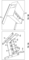
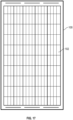
- a sample solar panel 100 is illustrated on FIGS. 17 and 18 , with the front side 102 of the solar panel as shown in FIG. 17 and the back side 104 of the solar panel as shown in FIG. 18 .
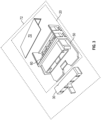
- FIG. 2A is a structural diagram illustrating the first embodiment of a universal solar junction box in a second perspective, which is attached to a solar panel for providing electrical connections to the solar panel and providing placement of electronics inside the universal solar junction box.
- FIG. 2B is a structural diagram illustrating the constituents of the universal solar junction box in the second perspective with three sub-assemblies assemblies: the junction box platform, the diode block, and the open-IP plug sub-assembly.
- the universal solar junction box 10 includes the junction box platform 20, which can be coupled to the diode block 30, which in turn can be coupled to the plug sub-assembly 40.
- the junction box platform 20 comprises the blade block 60, which can be inserted and coupled (or attached) to the base plate 50 with the cover for base plate 70.
- the diode block 30 or the second sub-assembly 30 includes one or more diodes for controlling the electrical current supplied to the universal solar junction box 10, and thus serves to prevent short circuiting in the associated solar panel.
- the open-IP plug sub-assembly includes the plug block 80 and the cable block 90.
- FIG. 3 is a structural diagram illustrating the constituents of the junction box platform 20 and the diode block 30.
- the blade block 60 is inserted into the base plate 50, with the cover 70, for coupling (or attaching) to the diode block 30.
- a combined sub-assembly of the junction box platform 20 and the diode block 30, collectively, are referred to as a junction box/diode block sub-assembly 72.
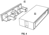
- FIG. 4 is a structural diagram illustrating the constituents of the open-IP plug sub-assembly 40, which includes the plug block 80 and the cable block 90.
- the concept of the open-IP plug sub-assembly is to provide a greater flexibility to manufacturers that have different specifications for plugging into the universal solar junction box 10.
- the various manufactures may have a block to mount onto the universal solar junction box 10, such as a micro inverter or solar module optimization box, as well as different number of cables, such as one cable (like an AC wire), two cables, four cables, etc.
- a manufacture can provide an inverter box for mounting onto the frame of the solar panel 100, and connectable to the open-IP plug sub-assembly 40, for converting direct current (DC) to alternating current (AC) to the solar module 100.
- a manufacturer can provide the solar module optimization box, to mount the open-IP plug sub-assembly 40, as a mechanism to monitor the solar module 100 and make adjustments to optimize the efficiency of the solar module 100 (or a plurality of solar modules).
- the concept of the open-IP plug sub-assembly is to provide a common interface (or platform) for various manufacturers that offers the flexibility to tailor their block (e.g., electrical/mechanical block with one or more wires) that is pluggable to the open-IP plug sub-assembly 40.
- the cable block 90 has one or more open gaps for wires or cables to extend between the inside and outside of the cable block 90.
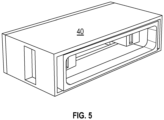
- the inverter or the solar module optimization box can be integrated into the open-IP sub-assembly 40. After inserting the cable block into the plug block 80 in the open-IPB sub-assembly 40, the resulting combination of the open-IP plug sub-assembly is shown in FIG. 5 .
- FIG. 6 is a structural diagram illustrating a combined sub-assembly of the junction box platform 20 with the diode block, the plug block 80, and the cable block 90.
- the junction box platform 20 (or the first sub-assembly) has assembled the base plate 50, the blade 60, and the cover 70 into one sub-assembly.
- the diode block 30 (or the second sub-assembly) is not shown in this figure.
- the open-IP sub-assembly (or the third sub-assembly) is illustrated with the plug block 80 and the cable block 90.
- FIG. 7 is a structural diagram illustrating the junction box platform 20 (the first sub-assembly), the diode block (the second sub-assembly), and the open-IP plug sub-assembly 40 (the third sub-assembly).
- the junction box platform 20 has been assembled into one sub-assembly in this figure to include the base plate 50, the blade 60, and the cover 70.
- the open-IP sub-assembly 40 has been assembled into one sub-assembly in this figure to include the plug block 80 and the cable block 90.
- the diode block 30 (“the replaceable diode block”), which is a modular unit that can be removed and singularly replace the defective diode block 30, rather than the entire solar junction box 10, is shown to be placed between the junction box platform 20 and the open-IP sub-assembly 40.
- FIG. 8 is a structural diagram illustrating the junction box platform 20 (the first sub-assembly), the diode block 30 (the second sub-assembly), and the open-IP plug sub-assembly 40 (the third sub-assembly) coupled with a cable sub-assembly 92.
- the cable sub-assembly 92 plugs into the cable block 80 and the plug block 90 in the open-IP plug sub-assembly 40.
- the cable sub-assembly 92 has a pair of cables that serve the solar module output with positive polarity and negative polarity.
- the cables or wires in the cable sub-assembly 92 are also replaceable and can be removed or unplugged from the open-IP sub-assembly for replacement, servicing, or testing of functions. After servicing or testing, the existing cable sub-assembly 92, if the part is operational, a new cable sub-assembly 92, is plugged back in to the cable sub-assembly 92.
- the cables on the cable sub-assembly 92 can be one or more DC cables or AC cables that operate as one or more micro-converters used to convert DC power to AC power.
- the cable sub-assembly 92 can be constructed from various embodiments to tailor to a specific device that will be plugged into the universal solar junction box 10.
- FIG. 9A is a structural diagram illustrating a first perspective of the base plate 50, the replaceable diode block 30, and an output cable sub-assembly 94.
- the base plate 50 is attached to the backside of the solar module 100.
- the base plate 50 is glued to the backside of the solar module 100.
- the output cable sub-assembly 94 includes the open-IP sub-assembly and one or more cables 92.
- FIG. 9A shows another perspective of the same components of the base plate 50, the replaceable diode block 30, and the output cable sub-assembly 94.
- FIG. 9A shows another perspective of the same components of the base plate 50, the replaceable diode block 30, and the output cable sub-assembly 94.
- 9C is a structural diagram illustrating the base plate 50 with a cage 46, the replaceable diode block 30, and the output cable sub-assembly 94 with a box cover 96.
- the box cover 96 can be placed over the cage 46 for assembling the base plate 50, the replaceable diode block 30, and the output cable sub-assembly 94.
- FIG. 10A is a structural diagram illustrating a horizontal embodiment of one or more locking latches 42a and 42b for affixing with the blade block 60.
- the base plate 50 is attached (such as glued) to the frame module and affixed (such as screwed) to the module frame 100 for additional strength to allow larger IME to be plugged.
- the IME includes electronics such as inverters, DC-DC optimizers, etc.
- an aluminum bar can also be inserted as part of the cage 46 for grounding.
- the blade block 60 extends through one or more slots 64a, 64b, 64c and 64d in the base plate 50 one or more electrical conducting blades 62a and 62b.
- Each of the electrical conducting blades 62a and 62b is inserted through a corresponding one of the slots 64a and 64b.
- a vertical embodiment with one or more locking latches for affixing with a vertical blade block 66 is illustrated in FIG. 10B .
- FIG. 11A is a structural diagram illustrating the vertical locking latch embodiment for affixing with the replaceable diode block 30.
- the replaceable diode block 30 includes one or more blade connectors 32a and 32b for plugging into the base plate 50. When the diode block 30 becomes defective, it can be easily unplugged from the base plate 50 and replaced with a new diode block 30.
- the modularity of the replaceable diode block 30 mitigates the expensive and cumbersome approach of having to replace the entire solar module when one of the diodes, which is sealed to a solar junction box, becomes defective.
- the reliability and life cycle of a diode can be a weak point in the solar module. If one of the diodes in a traditional sealed diode block is short circuited, the solution is relatively expensive in having to replace the entire solar module instead of just a diode block.
- FIG. 11B is a structural diagram illustrating the replaceable diode block 30 with spring connectors 36a and 36b for receiving and affixing to vertical locking latches 68.
- the replaceable diode block 30 includes three diodes 34a, 34b and 34c, that are pre-assembled in one block, as well as spring connectors 36a and 36b, electrical conducting blade connectors 32a and 32b, and one or more wires 38.
- the spring connector 36a is electrically connected to the diode 34a via a wire, which is electrically connected to the electrical conducting blade connection 32a via a wire 38a, which is electrically connected to the diode 34a via a wire 38b, which is electrically connected to the electrically conducting blade connector 32 via a wire 38c, which is electrically connected to the diode 34c via a wire 38d, and which is electrically connected to the spring connector 36b via a wire 38e.
- Each of the diodes 34a, 34b and 34c produce heat when active.
- the replaceable diode block 30 can include an optional heat dissipating silicone 31a within a cavity 31b of the replaceable diode block 30, thereby reducing or preventing overheating caused to one of the diodes.
- the heat dissipating silicone 31a can be filled throughout the entire cavity 31b of the replaceable diode block 30, or surrounding the exterior areas of the diodes 34a, 34b and 34c. Other types of heat dissipating materials that are suitable to operate with diodes can also be used.
- FIG. 12A is a structural diagram illustrating a first embodiment of the output cable sub-assembly 94 with a cover 96 for attaching to a pair of wires 92a and 92b.
- the cover 96 in the output cable sub-assembly 94 can be used to mechanically and electrically coupled to operate with any types of IMEs to service their customers.
- One benefit from this type of design is the allocation of warranties. While a first company, such as JA Solar, provides a solar module, including a junction box, and the associated warranty for the solar module, the second company who provides an IME for coupling to the cover 96 of the output cable sub-assembly 94 would provide the warranty for that portion of the electronics and part.
- FIG. 12B is a structural diagram illustrating a second embodiment of the output cable sub-assembly with a single wire 92c that is mechanically and electrically coupled to the cover of the output 98 cable sub-assembly 94.
- FIG. 13A is a structural diagram illustrating a horizontal assembly embodiment with the junction box platform 20, the diode block 30, and the output cable sub-assembly 94 (or open-IP plug sub-assembly 40 with the pair of cables 92a and 92b).
- the junction box platform 20 incudes the horizontal blade block 60, which has one or more horizontal blades that extend horizontally to the replaceable diode block 30.
- the open-IP plug sub-assembly 40 also has a horizontal construction for coupling to the replaceable diode block 30.
- 13B is a structural diagram illustrating a vertical assembly embodiment with the junction box platform 20, the diode block 30, and the output cable sub-assembly 95 (or the open-IP plug sub-assembly 40 and the pair of cables 92a and 92b).
- the junction box platform 20 incudes the vertical blade block 66, which has one or more vertical blades that extend vertical to the replaceable diode block 30.
- the open-IP plug sub-assembly 40 also has a vertical construction for coupling to the replaceable diode block 30.
- FIG. 14A is a structural diagram illustrating an embodiment of the universal solar junction box 10 attached to a solar module frame 106 of the solar module 100. Additional views of the universal solar junction box 10 are shown in FIGS. 14B-C .
- FIG. 15 is a structural diagram illustrating a second embodiment of the universal solar junction box 10 with a DC-to-DC optimizer 39 that can be plugged directly into the base plate 50 without the diode.
- Other alternative interface boxes can also be used in place of the DC-to-DC optimizer 39 or the replaceable diode block 30 for mechanically coupling between the junction box platform 20 and the open-IP sub-assembly.
- FIG. 14A is a structural diagram illustrating an embodiment of the universal solar junction box 10 attached to a solar module frame 106 of the solar module 100. Additional views of the universal solar junction box 10 are shown in FIGS. 14B-C .
- FIG. 15 is a structural diagram illustrating a second embodiment of the universal solar junction box 10 with a DC-to-DC optimizer 39
- 16 is a structural diagram illustrating a third embodiment of the universal solar junction box 10 with a micro-inverter 110 that can be plugged directly into the replaceable diode block 30 and coupling between the junction box platform 20 and the open-IP sub-assembly.
- a hardware module may be implemented mechanically or electronically.
- a hardware module may comprise dedicated circuitry or logic that is permanently configured (e.g., as a special-purpose processor, such as a field programmable gate array (FPGA) or an application-specific integrated circuit (ASIC)) to perform certain operations.
- a hardware module may also comprise programmable logic or circuitry (e.g., as encompassed within a general-purpose processor 712 or other programmable processor) that is temporarily configured by software to perform certain operations. It will be appreciated that the decision to implement a hardware module mechanically, in dedicated and permanently, configured circuitry, or in temporarily configured circuitry (e.g., configured by software) may be driven by cost and time considerations.
- the term "hardware module” should be understood to encompass a tangible entity, be that an entity that is physically constructed, permanently configured (e.g., hardwired) or temporarily configured (e.g., programmed) to operate in a certain manner and/or to perform certain operations described herein.
- hardware modules are temporarily configured (e.g., programmed)
- each of the hardware modules need not be configured or instantiated at any one instance in time.
- the hardware modules comprise a general-purpose processor configured to using software
- the general-purpose processor may be configured as respective different hardware modules at different times.
- Software may accordingly configure a processor, for example, to constitute a particular hardware module at one instance of time and to constitute a different hardware module at a different instance of time.
- Modules can provide information to, and receive information from, other modules.
- the described modules may be regarded as being communicatively coupled. Where multiples of such hardware modules exist contemporaneously, communications may be achieved through signal transmission (e.g., over appropriate circuits and buses) that connect the modules. In the embodiments where multiple modules are configured or instantiated at different times, communications between such modules may be achieved. For example, communications may occur through the storage and retrieval of information in memory structures where the multiple modules have access. For example, one module may perform an operation and store the output of that operation in a memory device to which it is communicatively coupled. A further module may, at a later time, access the memory device to retrieve and process the stored output. Modules may also initiate communications with input or output devices, and can operate on a resource (e.g., a collection of information).
- a resource e.g., a collection of information
- processors may be temporarily configured (e.g., by software, code, and/or instructions stored in a machine-readable medium) or permanently configured to perform the relevant operations.
- processors may constitute processor-implemented (or computer-implemented) modules that operate to perform one or more operations or functions.
- the modules referred to herein may, in some example embodiments, comprise processor-implemented (or computer-implemented) modules.
- any reference to "one embodiment” or “an embodiment” means that a particular element, feature, structure, or characteristic described in connection with the embodiment is included in at least one embodiment.
- the appearances of the phrase “in one embodiment” in various places in the specification are not necessarily all referring to the same embodiment.
- Coupled and “connected” along with their derivatives. It should be understood that these terms are not intended as synonyms for each other. For example, some embodiments may be described using the term “connected” to indicate that two or more elements are in direct physical or electrical contact with each other. In another example, some embodiments may be described using the term “coupled” to indicate that two or more elements are in direct physical or electrical contact. The term “coupled”, however, may also mean that two or more elements are not in direct contact with each other, but yet still co-operate or interact with each other. The embodiments are not limited in this context.
- the terms “comprises”, “comprising”, “includes”, “including”, “has”, “having” or any other variation thereof, are intended to cover a non-exclusive inclusion.
- a process, method, article, or apparatus that comprises a list of elements is not necessarily limited to only those elements but may include other elements not expressly listed or inherent to such process, method, article, or apparatus.
- "or” refers to an inclusive or and not to an exclusive or. For example, a condition A or B is satisfied by any one of the following: A is true (or present) and B is false (or not present), A is false (or not present) and B is true (or present), and both A and B are true (or present).
Landscapes
- Photovoltaic Devices (AREA)
Claims (12)
- Universelle Box (10) für Solarmodule, die auf einem Solarmodul (100) montiert ist, wobei die universelle Box (10) für Solarmodule aufweist:eine Anschlussboxplattform (20) mit einer Grundplatte (50), einem Klingenblock (60) und einer Abdeckung (70), wobei der Klingenblock (60) eine erste elektrisch leitende Klinge (62b) und eine zweite elektrisch leitende Klinge (62a) aufweist;einen modularen Diodenblock (30), der über den Klingenblock elektrisch und mechanisch mit der Anschlussboxplattform gekoppelt werden kann, wobei der modulare Diodenblock (30) einen ersten Federverbinder (36a) und einen zweiten Federverbinder (36b) aufweist, wobei sich die erste Klinge (62b) des Klingenblocks durch die Grundplatte erstreckt und durch den modularen Diodenblock (30) vorsteht,um eine elektrische Verbindung zwischen der ersten Klinge (62b) des Klingenblocks und dem ersten Federverbinder (36a) des modularen Diodenblocks (30) herzustellen,wobei sich die zweite Klinge (62a) des Klingenblocks durch die Grundplatte erstreckt und durch den modularen Diodenblock (30) vorsteht, um eine elektrische Verbindung zwischen der zweiten Klinge (62a) des Klingenblocks und dem zweiten Federverbinder (36b) des modularen Diodenblocks (30) herzustellen; undeine Steckerunterbaugruppe (40) mit einem Steckerblock (80) und einem Kabelblock (90), die an der Anschlussboxplattform und dem modularen Diodenblock (30) befestigt werden kann, wobei die Steckerunterbaugruppe eine Schutz bietende Abdeckung bereitstellt, um den modularen Diodenblock, den Klingenblock und den Kabelblock vor Witterungseinflüssen zu schützen, wobei der Kabelblock mechanisch an dem Steckerblock befestigt werden kann, wobei der Kabelblock mechanisch und elektrisch mit einem oder mehreren Ausgangskabeln (92) verbunden ist.
- Universelle Box für Solarmodule nach Anspruch 1, wobei der modulare Diodenblock (30) eine Mehrzahl von Dioden (34a, 34b, 34c) aufweist, wobei der modulare Diodenblock (30) ein austauschbares Bauteil ist, wenn eine der Dioden in dem modularen Diodenblock (30) ausfällt.
- Universelle Box für Module nach einem der vorhergehenden Ansprüche, wobei der modulare Diodenblock (30) drei Dioden (34a, 34b, 34c) zum Schutz einer Mehrzahl von Solarzellen auf dem Solarmodul aufweist.
- Universelle Box für Module nach Anspruch 3, wobei die drei Dioden miteinander verbunden sind und der modulare Diodenblock (30) ferner aufweist:den ersten Federverbinder (36a) zum Herstellen einer ersten externen Verbindung des modularen Diodenblocks (30), wobei der erste Verbinder mit einem Ende der drei Dioden gekoppelt ist; undden zweiten Federverbinder (36b) zum Herstellen einer zweiten externen Verbindung des modularen Diodenblocks (30), wobei der zweite Verbinder mit dem anderen Ende der drei Dioden verbunden ist.
- Universelle Box für Solarmodule nach Anspruch 4, wobei der modulare Diodenblock (30) wärmeableitendes Material (31a) aufweist, das jede der drei Dioden umgibt.
- Universelle Box für Solarmodule nach Anspruch 1, wobei der modulare Diodenblock (30) wenigstens eine Diode (34a, 34b, 34c) aufweist.
- Universelle Box für Solarmodule nach einem der vorhergehenden Ansprüche, wobei die Steckerunterbaugruppe so konfiguriert ist, dass sie mit einem Paar von Kabeln (92a, 92b) verbunden werden kann.
- Universelle Box für Solarmodule nach einem der Ansprüche 1 bis 5, wobei die Steckerunterbaugruppe so konfiguriert ist, dass sie mit einem einzigen Kabel (92c) verbunden werden kann.
- Universelle Box für Solarmodule nach einem der vorhergehenden Ansprüche, wobei die Anschlussboxplattform einen Käfig (46) aufweist, der so konfiguriert ist, dass er mechanisch an dem Solarmodulrahmen und der Grundplatte befestigt werden kann, um die physische Last von der Grundplatte auf den Rahmen zu verteilen.
- Universelle Box für Solarmodule nach einem der vorhergehenden Ansprüche, wobei die Steckerunterbaugruppe einen oder mehrere Mikro-Wechselrichter (110) aufweist.
- Universelle Box für Solarmodule nach Anspruch 10, wobei die Steckerunterbaugruppe einen oder mehrere Mikro-Wechselrichter (110) und Elektronik aufweist.
- Universelle Box für Solarmodule nach einem der vorhergehenden Ansprüche, wobei die Abdeckung so konfiguriert ist, dass sie eine Abdeckung über dem Klingenblock und der Grundplatte bildet.
Applications Claiming Priority (2)
| Application Number | Priority Date | Filing Date | Title |
|---|---|---|---|
| US201562169758P | 2015-06-02 | 2015-06-02 | |
| PCT/US2016/035519 WO2016196794A1 (en) | 2015-06-02 | 2016-06-02 | Apparatus and method of a universal module junction box |
Publications (3)
| Publication Number | Publication Date |
|---|---|
| EP3304729A1 EP3304729A1 (de) | 2018-04-11 |
| EP3304729A4 EP3304729A4 (de) | 2019-01-09 |
| EP3304729B1 true EP3304729B1 (de) | 2025-03-05 |
Family
ID=61521861
Family Applications (1)
| Application Number | Title | Priority Date | Filing Date |
|---|---|---|---|
| EP16804436.0A Active EP3304729B1 (de) | 2015-06-02 | 2016-06-02 | Vorrichtung eines universalanschlusskastens für module |
Country Status (1)
| Country | Link |
|---|---|
| EP (1) | EP3304729B1 (de) |
Citations (1)
| Publication number | Priority date | Publication date | Assignee | Title |
|---|---|---|---|---|
| EP0793278B1 (de) * | 1996-01-29 | 2009-07-08 | Sanyo Electric Co. Ltd | Photovoltaische Anordnung |
Family Cites Families (3)
| Publication number | Priority date | Publication date | Assignee | Title |
|---|---|---|---|---|
| DE10331780B4 (de) * | 2003-07-11 | 2005-06-09 | Günther Spelsberg GmbH & Co. KG | Elektrische Anschluß- und Verbindungsdose |
| CH705107A2 (de) * | 2011-06-03 | 2012-12-14 | Huber+Suhner Ag | Modulare Solardose. |
| US9685904B2 (en) * | 2013-10-16 | 2017-06-20 | General Electric Company | Photovoltaic system with improved DC connections and method of making same |
-
2016
- 2016-06-02 EP EP16804436.0A patent/EP3304729B1/de active Active
Patent Citations (1)
| Publication number | Priority date | Publication date | Assignee | Title |
|---|---|---|---|---|
| EP0793278B1 (de) * | 1996-01-29 | 2009-07-08 | Sanyo Electric Co. Ltd | Photovoltaische Anordnung |
Also Published As
| Publication number | Publication date |
|---|---|
| EP3304729A4 (de) | 2019-01-09 |
| EP3304729A1 (de) | 2018-04-11 |
Similar Documents
| Publication | Publication Date | Title |
|---|---|---|
| US10008979B2 (en) | Integration of microinverter with photovoltaic module | |
| US20150188486A1 (en) | Alternating current photovoltaic module | |
| US20170269919A1 (en) | Photovoltaic module integrated mounting and electronics systems | |
| KR20100017853A (ko) | 광전지 ac 인버터 장착 및 상호접속 | |
| US10903787B2 (en) | Apparatus and method of a universal module junction box | |
| US20100275991A1 (en) | Photovoltaic System, a Terminal Box Thereof and a Voltage Converting Device | |
| US9685904B2 (en) | Photovoltaic system with improved DC connections and method of making same | |
| US20140196770A1 (en) | Photovoltaic module and system | |
| WO2015054459A1 (en) | Power conversion and connection for photovoltaic (pv) panel arrays | |
| KR102377270B1 (ko) | 전력 전자 기기를 광기전 모듈에 연결하기 위한 장치 및 시스템 | |
| KR101505186B1 (ko) | 태양 전지 모듈 | |
| US20160079907A1 (en) | Field-assembled ac photovoltaic module | |
| CN105850033A (zh) | 光伏模块接线盒 | |
| US10069457B2 (en) | System for mounting a microinverter to a photovoltaic panel and method of making same | |
| JP4798956B2 (ja) | 太陽電池モジュールおよびそれを用いた太陽光発電装置 | |
| EP3304729A1 (de) | Vorrichtung und verfahren universalanschlusskastens für module | |
| KR101539653B1 (ko) | 결정질 모듈용 태양광 정션박스 | |
| CN207099029U (zh) | 一种光伏发电系统 | |
| CN104115279B (zh) | 太阳能电池组件 | |
| TWM488784U (zh) | 接線盒 | |
| CN106160655A (zh) | 光伏组件接线盒 | |
| WO2014204398A1 (en) | An ac solar module | |
| KR20180126982A (ko) | 태양광 모듈 | |
| CN201754410U (zh) | 一种智能光伏组件及光伏系统 | |
| CN202231040U (zh) | 连接端子的散热结构 |
Legal Events
| Date | Code | Title | Description |
|---|---|---|---|
| STAA | Information on the status of an ep patent application or granted ep patent |
Free format text: STATUS: THE INTERNATIONAL PUBLICATION HAS BEEN MADE |
|
| PUAI | Public reference made under article 153(3) epc to a published international application that has entered the european phase |
Free format text: ORIGINAL CODE: 0009012 |
|
| STAA | Information on the status of an ep patent application or granted ep patent |
Free format text: STATUS: REQUEST FOR EXAMINATION WAS MADE |
|
| 17P | Request for examination filed |
Effective date: 20170914 |
|
| AK | Designated contracting states |
Kind code of ref document: A1 Designated state(s): AL AT BE BG CH CY CZ DE DK EE ES FI FR GB GR HR HU IE IS IT LI LT LU LV MC MK MT NL NO PL PT RO RS SE SI SK SM TR |
|
| AX | Request for extension of the european patent |
Extension state: BA ME |
|
| DAV | Request for validation of the european patent (deleted) | ||
| DAX | Request for extension of the european patent (deleted) | ||
| A4 | Supplementary search report drawn up and despatched |
Effective date: 20181207 |
|
| RIC1 | Information provided on ipc code assigned before grant |
Ipc: H02S 40/32 20140101ALI20181203BHEP Ipc: H01L 31/042 20140101ALI20181203BHEP Ipc: H02S 40/34 20140101AFI20181203BHEP |
|
| STAA | Information on the status of an ep patent application or granted ep patent |
Free format text: STATUS: EXAMINATION IS IN PROGRESS |
|
| 17Q | First examination report despatched |
Effective date: 20200526 |
|
| GRAP | Despatch of communication of intention to grant a patent |
Free format text: ORIGINAL CODE: EPIDOSNIGR1 |
|
| STAA | Information on the status of an ep patent application or granted ep patent |
Free format text: STATUS: GRANT OF PATENT IS INTENDED |
|
| INTG | Intention to grant announced |
Effective date: 20240712 |
|
| GRAJ | Information related to disapproval of communication of intention to grant by the applicant or resumption of examination proceedings by the epo deleted |
Free format text: ORIGINAL CODE: EPIDOSDIGR1 |
|
| STAA | Information on the status of an ep patent application or granted ep patent |
Free format text: STATUS: EXAMINATION IS IN PROGRESS |
|
| INTC | Intention to grant announced (deleted) | ||
| GRAP | Despatch of communication of intention to grant a patent |
Free format text: ORIGINAL CODE: EPIDOSNIGR1 |
|
| STAA | Information on the status of an ep patent application or granted ep patent |
Free format text: STATUS: GRANT OF PATENT IS INTENDED |
|
| INTG | Intention to grant announced |
Effective date: 20241216 |
|
| GRAS | Grant fee paid |
Free format text: ORIGINAL CODE: EPIDOSNIGR3 |
|
| GRAA | (expected) grant |
Free format text: ORIGINAL CODE: 0009210 |
|
| STAA | Information on the status of an ep patent application or granted ep patent |
Free format text: STATUS: THE PATENT HAS BEEN GRANTED |
|
| P01 | Opt-out of the competence of the unified patent court (upc) registered |
Free format text: CASE NUMBER: APP_3210/2025 Effective date: 20250121 |
|
| AK | Designated contracting states |
Kind code of ref document: B1 Designated state(s): AL AT BE BG CH CY CZ DE DK EE ES FI FR GB GR HR HU IE IS IT LI LT LU LV MC MK MT NL NO PL PT RO RS SE SI SK SM TR |
|
| REG | Reference to a national code |
Ref country code: GB Ref legal event code: FG4D |
|
| REG | Reference to a national code |
Ref country code: CH Ref legal event code: EP |
|
| REG | Reference to a national code |
Ref country code: IE Ref legal event code: FG4D |
|
| REG | Reference to a national code |
Ref country code: DE Ref legal event code: R096 Ref document number: 602016091456 Country of ref document: DE |
|
| PG25 | Lapsed in a contracting state [announced via postgrant information from national office to epo] |
Ref country code: RS Free format text: LAPSE BECAUSE OF FAILURE TO SUBMIT A TRANSLATION OF THE DESCRIPTION OR TO PAY THE FEE WITHIN THE PRESCRIBED TIME-LIMIT Effective date: 20250605 |
|
| PG25 | Lapsed in a contracting state [announced via postgrant information from national office to epo] |
Ref country code: FI Free format text: LAPSE BECAUSE OF FAILURE TO SUBMIT A TRANSLATION OF THE DESCRIPTION OR TO PAY THE FEE WITHIN THE PRESCRIBED TIME-LIMIT Effective date: 20250305 |
|
| REG | Reference to a national code |
Ref country code: NL Ref legal event code: MP Effective date: 20250305 |
|
| PG25 | Lapsed in a contracting state [announced via postgrant information from national office to epo] |
Ref country code: ES Free format text: LAPSE BECAUSE OF FAILURE TO SUBMIT A TRANSLATION OF THE DESCRIPTION OR TO PAY THE FEE WITHIN THE PRESCRIBED TIME-LIMIT Effective date: 20250305 |
|
| PGFP | Annual fee paid to national office [announced via postgrant information from national office to epo] |
Ref country code: GB Payment date: 20250621 Year of fee payment: 10 |
|
| REG | Reference to a national code |
Ref country code: LT Ref legal event code: MG9D |
|
| PG25 | Lapsed in a contracting state [announced via postgrant information from national office to epo] |
Ref country code: NO Free format text: LAPSE BECAUSE OF FAILURE TO SUBMIT A TRANSLATION OF THE DESCRIPTION OR TO PAY THE FEE WITHIN THE PRESCRIBED TIME-LIMIT Effective date: 20250605 |
|
| PG25 | Lapsed in a contracting state [announced via postgrant information from national office to epo] |
Ref country code: HR Free format text: LAPSE BECAUSE OF FAILURE TO SUBMIT A TRANSLATION OF THE DESCRIPTION OR TO PAY THE FEE WITHIN THE PRESCRIBED TIME-LIMIT Effective date: 20250305 |
|
| PG25 | Lapsed in a contracting state [announced via postgrant information from national office to epo] |
Ref country code: LV Free format text: LAPSE BECAUSE OF FAILURE TO SUBMIT A TRANSLATION OF THE DESCRIPTION OR TO PAY THE FEE WITHIN THE PRESCRIBED TIME-LIMIT Effective date: 20250305 |
|
| PGFP | Annual fee paid to national office [announced via postgrant information from national office to epo] |
Ref country code: FR Payment date: 20250617 Year of fee payment: 10 |
|
| PG25 | Lapsed in a contracting state [announced via postgrant information from national office to epo] |
Ref country code: GR Free format text: LAPSE BECAUSE OF FAILURE TO SUBMIT A TRANSLATION OF THE DESCRIPTION OR TO PAY THE FEE WITHIN THE PRESCRIBED TIME-LIMIT Effective date: 20250606 Ref country code: BG Free format text: LAPSE BECAUSE OF FAILURE TO SUBMIT A TRANSLATION OF THE DESCRIPTION OR TO PAY THE FEE WITHIN THE PRESCRIBED TIME-LIMIT Effective date: 20250305 |
|
| REG | Reference to a national code |
Ref country code: AT Ref legal event code: MK05 Ref document number: 1773889 Country of ref document: AT Kind code of ref document: T Effective date: 20250305 |
|
| PG25 | Lapsed in a contracting state [announced via postgrant information from national office to epo] |
Ref country code: NL Free format text: LAPSE BECAUSE OF FAILURE TO SUBMIT A TRANSLATION OF THE DESCRIPTION OR TO PAY THE FEE WITHIN THE PRESCRIBED TIME-LIMIT Effective date: 20250305 |
|
| PG25 | Lapsed in a contracting state [announced via postgrant information from national office to epo] |
Ref country code: SE Free format text: LAPSE BECAUSE OF FAILURE TO SUBMIT A TRANSLATION OF THE DESCRIPTION OR TO PAY THE FEE WITHIN THE PRESCRIBED TIME-LIMIT Effective date: 20250305 |
|
| PG25 | Lapsed in a contracting state [announced via postgrant information from national office to epo] |
Ref country code: SM Free format text: LAPSE BECAUSE OF FAILURE TO SUBMIT A TRANSLATION OF THE DESCRIPTION OR TO PAY THE FEE WITHIN THE PRESCRIBED TIME-LIMIT Effective date: 20250305 |
|
| PG25 | Lapsed in a contracting state [announced via postgrant information from national office to epo] |
Ref country code: PT Free format text: LAPSE BECAUSE OF FAILURE TO SUBMIT A TRANSLATION OF THE DESCRIPTION OR TO PAY THE FEE WITHIN THE PRESCRIBED TIME-LIMIT Effective date: 20250707 |
|
| PGFP | Annual fee paid to national office [announced via postgrant information from national office to epo] |
Ref country code: DE Payment date: 20250630 Year of fee payment: 10 |
|
| PG25 | Lapsed in a contracting state [announced via postgrant information from national office to epo] |
Ref country code: PL Free format text: LAPSE BECAUSE OF FAILURE TO SUBMIT A TRANSLATION OF THE DESCRIPTION OR TO PAY THE FEE WITHIN THE PRESCRIBED TIME-LIMIT Effective date: 20250305 Ref country code: IT Free format text: LAPSE BECAUSE OF FAILURE TO SUBMIT A TRANSLATION OF THE DESCRIPTION OR TO PAY THE FEE WITHIN THE PRESCRIBED TIME-LIMIT Effective date: 20250305 |
|
| PG25 | Lapsed in a contracting state [announced via postgrant information from national office to epo] |
Ref country code: AT Free format text: LAPSE BECAUSE OF FAILURE TO SUBMIT A TRANSLATION OF THE DESCRIPTION OR TO PAY THE FEE WITHIN THE PRESCRIBED TIME-LIMIT Effective date: 20250305 |
|
| PG25 | Lapsed in a contracting state [announced via postgrant information from national office to epo] |
Ref country code: EE Free format text: LAPSE BECAUSE OF FAILURE TO SUBMIT A TRANSLATION OF THE DESCRIPTION OR TO PAY THE FEE WITHIN THE PRESCRIBED TIME-LIMIT Effective date: 20250305 Ref country code: CZ Free format text: LAPSE BECAUSE OF FAILURE TO SUBMIT A TRANSLATION OF THE DESCRIPTION OR TO PAY THE FEE WITHIN THE PRESCRIBED TIME-LIMIT Effective date: 20250305 |
|
| PG25 | Lapsed in a contracting state [announced via postgrant information from national office to epo] |
Ref country code: RO Free format text: LAPSE BECAUSE OF FAILURE TO SUBMIT A TRANSLATION OF THE DESCRIPTION OR TO PAY THE FEE WITHIN THE PRESCRIBED TIME-LIMIT Effective date: 20250305 |
|
| PG25 | Lapsed in a contracting state [announced via postgrant information from national office to epo] |
Ref country code: SK Free format text: LAPSE BECAUSE OF FAILURE TO SUBMIT A TRANSLATION OF THE DESCRIPTION OR TO PAY THE FEE WITHIN THE PRESCRIBED TIME-LIMIT Effective date: 20250305 |
|
| PG25 | Lapsed in a contracting state [announced via postgrant information from national office to epo] |
Ref country code: IS Free format text: LAPSE BECAUSE OF FAILURE TO SUBMIT A TRANSLATION OF THE DESCRIPTION OR TO PAY THE FEE WITHIN THE PRESCRIBED TIME-LIMIT Effective date: 20250705 |
|
| REG | Reference to a national code |
Ref country code: DE Ref legal event code: R097 Ref document number: 602016091456 Country of ref document: DE |
|
| PLBE | No opposition filed within time limit |
Free format text: ORIGINAL CODE: 0009261 |
|
| STAA | Information on the status of an ep patent application or granted ep patent |
Free format text: STATUS: NO OPPOSITION FILED WITHIN TIME LIMIT |
|
| PG25 | Lapsed in a contracting state [announced via postgrant information from national office to epo] |
Ref country code: DK Free format text: LAPSE BECAUSE OF FAILURE TO SUBMIT A TRANSLATION OF THE DESCRIPTION OR TO PAY THE FEE WITHIN THE PRESCRIBED TIME-LIMIT Effective date: 20250305 |
|
| REG | Reference to a national code |
Ref country code: CH Ref legal event code: L10 Free format text: ST27 STATUS EVENT CODE: U-0-0-L10-L00 (AS PROVIDED BY THE NATIONAL OFFICE) Effective date: 20260114 |
|
| REG | Reference to a national code |
Ref country code: CH Ref legal event code: H13 Free format text: ST27 STATUS EVENT CODE: U-0-0-H10-H13 (AS PROVIDED BY THE NATIONAL OFFICE) Effective date: 20260127 |
|
| PG25 | Lapsed in a contracting state [announced via postgrant information from national office to epo] |
Ref country code: MC Free format text: LAPSE BECAUSE OF FAILURE TO SUBMIT A TRANSLATION OF THE DESCRIPTION OR TO PAY THE FEE WITHIN THE PRESCRIBED TIME-LIMIT Effective date: 20250305 |
|
| 26N | No opposition filed |
Effective date: 20251208 |
|
| PG25 | Lapsed in a contracting state [announced via postgrant information from national office to epo] |
Ref country code: LU Free format text: LAPSE BECAUSE OF NON-PAYMENT OF DUE FEES Effective date: 20250602 |
|
| REG | Reference to a national code |
Ref country code: BE Ref legal event code: MM Effective date: 20250630 |
|
| PG25 | Lapsed in a contracting state [announced via postgrant information from national office to epo] |
Ref country code: IE Free format text: LAPSE BECAUSE OF NON-PAYMENT OF DUE FEES Effective date: 20250602 |
|
| PG25 | Lapsed in a contracting state [announced via postgrant information from national office to epo] |
Ref country code: BE Free format text: LAPSE BECAUSE OF NON-PAYMENT OF DUE FEES Effective date: 20250630 |
|
| PG25 | Lapsed in a contracting state [announced via postgrant information from national office to epo] |
Ref country code: CH Free format text: LAPSE BECAUSE OF NON-PAYMENT OF DUE FEES Effective date: 20250630 |