EP3304766B1 - Émetteur-récepteur à mode de fonctionnement alternatif - Google Patents
Émetteur-récepteur à mode de fonctionnement alternatif Download PDFInfo
- Publication number
- EP3304766B1 EP3304766B1 EP15724696.8A EP15724696A EP3304766B1 EP 3304766 B1 EP3304766 B1 EP 3304766B1 EP 15724696 A EP15724696 A EP 15724696A EP 3304766 B1 EP3304766 B1 EP 3304766B1
- Authority
- EP
- European Patent Office
- Prior art keywords
- signal
- mode
- transceiver
- polarization
- antenna
- Prior art date
- Legal status (The legal status is an assumption and is not a legal conclusion. Google has not performed a legal analysis and makes no representation as to the accuracy of the status listed.)
- Active
Links
Images
Classifications
-
- H—ELECTRICITY
- H04—ELECTRIC COMMUNICATION TECHNIQUE
- H04B—TRANSMISSION
- H04B1/00—Details of transmission systems, not covered by a single one of groups H04B3/00 - H04B13/00; Details of transmission systems not characterised by the medium used for transmission
- H04B1/38—Transceivers, i.e. devices in which transmitter and receiver form a structural unit and in which at least one part is used for functions of transmitting and receiving
- H04B1/40—Circuits
- H04B1/54—Circuits using the same frequency for two directions of communication
- H04B1/56—Circuits using the same frequency for two directions of communication with provision for simultaneous communication in two directions
-
- H—ELECTRICITY
- H04—ELECTRIC COMMUNICATION TECHNIQUE
- H04B—TRANSMISSION
- H04B7/00—Radio transmission systems, i.e. using radiation field
- H04B7/02—Diversity systems; Multi-antenna system, i.e. transmission or reception using multiple antennas
- H04B7/04—Diversity systems; Multi-antenna system, i.e. transmission or reception using multiple antennas using two or more spaced independent antennas
- H04B7/06—Diversity systems; Multi-antenna system, i.e. transmission or reception using multiple antennas using two or more spaced independent antennas at the transmitting station
- H04B7/0686—Hybrid systems, i.e. switching and simultaneous transmission
- H04B7/0689—Hybrid systems, i.e. switching and simultaneous transmission using different transmission schemes, at least one of them being a diversity transmission scheme
-
- H—ELECTRICITY
- H04—ELECTRIC COMMUNICATION TECHNIQUE
- H04B—TRANSMISSION
- H04B1/00—Details of transmission systems, not covered by a single one of groups H04B3/00 - H04B13/00; Details of transmission systems not characterised by the medium used for transmission
- H04B1/38—Transceivers, i.e. devices in which transmitter and receiver form a structural unit and in which at least one part is used for functions of transmitting and receiving
- H04B1/40—Circuits
- H04B1/401—Circuits for selecting or indicating operating mode
-
- H—ELECTRICITY
- H04—ELECTRIC COMMUNICATION TECHNIQUE
- H04B—TRANSMISSION
- H04B7/00—Radio transmission systems, i.e. using radiation field
- H04B7/02—Diversity systems; Multi-antenna system, i.e. transmission or reception using multiple antennas
- H04B7/04—Diversity systems; Multi-antenna system, i.e. transmission or reception using multiple antennas using two or more spaced independent antennas
- H04B7/08—Diversity systems; Multi-antenna system, i.e. transmission or reception using multiple antennas using two or more spaced independent antennas at the receiving station
- H04B7/0868—Hybrid systems, i.e. switching and combining
- H04B7/0871—Hybrid systems, i.e. switching and combining using different reception schemes, at least one of them being a diversity reception scheme
-
- H—ELECTRICITY
- H04—ELECTRIC COMMUNICATION TECHNIQUE
- H04B—TRANSMISSION
- H04B7/00—Radio transmission systems, i.e. using radiation field
- H04B7/02—Diversity systems; Multi-antenna system, i.e. transmission or reception using multiple antennas
- H04B7/10—Polarisation diversity; Directional diversity
-
- H—ELECTRICITY
- H04—ELECTRIC COMMUNICATION TECHNIQUE
- H04B—TRANSMISSION
- H04B7/00—Radio transmission systems, i.e. using radiation field
- H04B7/02—Diversity systems; Multi-antenna system, i.e. transmission or reception using multiple antennas
- H04B7/04—Diversity systems; Multi-antenna system, i.e. transmission or reception using multiple antennas using two or more spaced independent antennas
- H04B7/06—Diversity systems; Multi-antenna system, i.e. transmission or reception using multiple antennas using two or more spaced independent antennas at the transmitting station
- H04B7/0613—Diversity systems; Multi-antenna system, i.e. transmission or reception using multiple antennas using two or more spaced independent antennas at the transmitting station using simultaneous transmission
- H04B7/0615—Diversity systems; Multi-antenna system, i.e. transmission or reception using multiple antennas using two or more spaced independent antennas at the transmitting station using simultaneous transmission of weighted versions of same signal
- H04B7/0619—Diversity systems; Multi-antenna system, i.e. transmission or reception using multiple antennas using two or more spaced independent antennas at the transmitting station using simultaneous transmission of weighted versions of same signal using feedback from receiving side
- H04B7/0621—Feedback content
- H04B7/0626—Channel coefficients, e.g. channel state information [CSI]
-
- H—ELECTRICITY
- H04—ELECTRIC COMMUNICATION TECHNIQUE
- H04L—TRANSMISSION OF DIGITAL INFORMATION, e.g. TELEGRAPHIC COMMUNICATION
- H04L25/00—Baseband systems
- H04L25/02—Details ; arrangements for supplying electrical power along data transmission lines
- H04L25/0202—Channel estimation
Definitions
- the present invention relates to the field of transceivers for wireless communication.
- a characterization of the communication channel may be determined (e.g. estimated) and used to improve performance (e.g. capacity, throughput, error rate, etc.) of future communication (transmission and/or reception).
- performance e.g. capacity, throughput, error rate, etc.
- channel characterization include channel state information (CSI), channel quality indication (CQI), and channel impulse response estimates in general.
- CSI channel state information
- CQI channel quality indication
- channel impulse response estimates in general.
- Well known ways to apply the channel characterization include pre-coding (e.g. beam forming for multi-antenna systems such as multiple input multiple output (MIMO) systems, phase array systems, and massive MIMO systems).
- a first device transmitting to a second device over a communication channel uses a channel characterization produced by the second device to improve performance related to its transmission.
- the channel characterization may typically be conveyed from the second device to the first device through some kind of feed-back mechanism.
- Example drawbacks of such an approach include increased signaling overhead, limited channel characterization accuracy (due to quantization of the information to be fed back), and delayed update of the applied channel characterization by the first device.
- TDD time division duplex
- reciprocity may be assumed and a channel characterization produced by the first device may be used by the first device to improve performance related to its transmission, instead of a channel characterization produced by the second device. It is often assumed that TDD must be used for some systems to work efficiently.
- fifth generation communication systems applying massive MIMO where a TDD mode of operation is often selected at least partly due to the above mentioned feedback issues.
- Example drawbacks of such an approach include increased buffering needs at the transmitter (due to the transmission interruptions inherent in TDD) and increased latency (also due to the transmission interruptions inherent in TDD).
- Other drawbacks of TDD include reduced throughput, slow update of the applied channel characterization, and inferior synchronization.
- WO 2014/202156 A1 discloses a transceiver arrangement for a fixed point-to-point radio link.
- the transceiver arrangement comprising a transceiver connected to a first antenna and to a second antenna.
- the transceiver being arranged to transmit a first transmit signal via the first antenna in a first frequency band
- the transceiver also being arranged to receive a first receive signal via the first antenna in a second frequency band
- the transceiver further being arranged to transmit a second transmit signal via the second antenna in the second frequency band
- the transceiver also being arranged to receive a second receive signal via the second antenna in the first frequency band.
- a wireless communication system includes a first transceiver configured to transmit and receive wireless signals to and from at least a second transceiver.
- the first transceiver includes a plurality of transmitter antennas and a plurality of receiver antennas. At least one of the transmitter antennas is configured to transmit a first signal with a first polarization weight to at least the second transceiver.
- At least one of the receiver antennas is configured to receive a second signal with a second polarization from the second transceiver. The second polarization is cross polarized with the first polarization.
- the inventors have realized that signals can advantageously be transmitted between nodes by using different polarization in different directions, and alternating the polarization over time.
- a transceiver for a communication node adapted to transmit a first signal to an other communication node and to receive a second signal from the other communication node.
- the transceiver comprises at least one antenna, at least one transmitter module, at least one receiver module, and a mode alternator.
- the at least one antenna is adapted to simultaneously transmit the first signal and receive the second signal.
- the first and second signals have equal carrier frequencies and different polarizations.
- the second signal is for determining a channel characterization of a communication channel over which the second signal is received, and the channel characterization is for determination of one or more transmission parameters for the first signal.
- the at least one transmitter module is adapted to process the first signal before transmission by the at least one antenna and the at least one receiver module is adapted to process the second signal after reception by the at least one antenna.
- the mode alternator is adapted to alternate a mode of operation of the transceiver between at least a first and a second mode of operation.
- the first mode of operation comprises the transceiver transmitting the first signal using a first polarization and receiving the second signal using a second polarization.
- the second mode of operation comprises the transceiver transmitting the first signal using a third polarization and receiving the second signal using a fourth polarization.
- the at least one receiver module is adapted to detect interruption in the received second signal and interpret the interruption as initiation of alternation of the mode of operation.
- the mode alternator is adapted to alternate the mode of operation responsive to detection of the interruption.
- the alternation between different modes of operation may typically be synchronized between transmission and reception parts of the transceiver.
- a guard interval may be applied to accommodate the alternation.
- the communication node may be a network node (such as, for example, a base station, a NodeB, an eNodeB, etc.).
- a network node such as, for example, a base station, a NodeB, an eNodeB, etc.
- the at least one antenna may, for example, be an antenna system, an antenna array, an antenna matrix, or similar.
- Processing by the transmitter and receiver modules may comprise any suitable processing (such as, for example, amplification, gain control, filtering, adaptive filtering, analog-to-digital conversion, digital-to-analog conversion, etc.).
- suitable processing such as, for example, amplification, gain control, filtering, adaptive filtering, analog-to-digital conversion, digital-to-analog conversion, etc.
- the channel characterization may, for example, comprise a channel estimate or a channel quality metric.
- Examples of channel characterizations include channel state information (CSI) and channel quality indication (CQI).
- the channel characterization may, for example, be determined by using any suitable method, for example, a least mean square (LMS) approach or a minimum mean square error (MMSE) approach.
- LMS least mean square
- MMSE minimum mean square error
- the different polarizations of the first and second signals are typically orthogonal (e.g. 90 degrees relative to each other). However, leakage between polarizations may occur in some embodiments. Hence, one or more of the first and second signals may comprise (minor) components of the other signal.
- the first polarization is different from the third polarization and the second polarization is different from the fourth polarization.
- the third polarization equals the second polarization and the fourth polarization may equal the first polarization.
- Such embodiments may, for example, be embodiments with only two modes of operation.
- the mode alternator may be adapted to sequentially apply any suitable pairs of orthogonal polarization for transmission and reception, respectively.
- the one or more transmission parameters may comprise pre-coding coefficients and the transceiver may further comprise a channel estimator adapted to provide the channel characterization based on the processed second signal and a pre-coder adapted to apply the pre-coding coefficients to the first signal before processing by the at least one transmitter module.
- Pre-coding coefficients may, for example, be used for beam-forming in MIMO systems.
- the one or more transmission parameters may comprise modulation and coding schemes (MCS).
- MCS modulation and coding schemes
- the at least one transmitter module may comprise first and second transmitter modules adapted to process the first signal according to the first and second polarization, respectively, and the at least one receiver module may comprise first and receiver modules adapted to process the second signal according to the first and second polarization, respectively.
- the mode alternator may comprise a signal distribution network adapted to:
- determination of the channel characterization based on an output of the second receiver module may be caused by operatively connecting a channel estimator to the second receiver module during the first duration of time.
- the mode alternator may, in these embodiments, be adapted to connect the at least one antenna to the first and second transmitter modules and to the first and second receiver modules via a polarization duplexer (e.g. an ortho-mode, transducer (OMT), a polarization duplexer).
- a polarization duplexer e.g. an ortho-mode, transducer (OMT), a polarization duplexer
- the at least one antenna may comprise a first antenna system adapted to transmit and receive signals according to the first polarization and a second antenna system adapted to transmit and receive signals according to the second polarization.
- the mode alternator may comprise a signal distribution network adapted to:
- the signal distribution networks may, for example, comprise any or more of connectors, switches, and signal routing means, as suitable.
- the signal distribution network may operatively connect all applicable components (antenna(s), transmitter/receiver module(s), channel estimator, pre-coder, etc.) as suitable at all times, and each of the respective components may have a selector for selecting which connections (e.g. ports) to use during a particular duration of time.
- the mode alternator may be adapted to alternate the mode of operation periodically.
- the period of the periodical alternation may be static or dynamic.
- the period may be based on how often a deterioration of a performance metric is detected or on a worst case interval for updating the transmission parameters.
- the mode alternator may be adapted to alternate the mode of operation based on a (possibly estimated) coherence time of the communication channel.
- the mode alternator may be adapted to alternate the mode of operation when a deterioration of a performance metric is detected. In some embodiments, this approach may be combined with the mode alternator being further adapted to alternate the mode of operation when a maximum time interval has elapsed since a previous alternation.
- the deterioration may be manifested as an increase or a decrease of the performance metric depending on which metric is used.
- performance metrics include channel estimation value, bit error rate (BER), signal-to-noise ratio (SNR), signal-to-interference ratio (SIR), signal-to-noise-and-interference ratio (SNIR), received signal strength indicator (RSSI), etc.
- the at least one transmitter module may be adapted to stop the transmission of the first signal to initiate alternation of the mode of operation.
- the at least one receiver module may be adapted to detect interruption in the received second signal after the transmission of the first signal has been stopped and the mode alternator may be adapted to alternate the mode of operation responsive to detection of the interruption.
- the at least one transmitter module may be adapted to resume the transmission of the first signal after the mode of operation has been alternated.
- the transceiver may (as an alternative to detecting interruption in the received second signal and alternating the mode of operation responsive to detection of the interruption) be adapted to alternate the mode of operation when twice a transfer time between the communication node and the other communication node has elapsed.
- the transfer time may be known beforehand by the transceiver or the transceiver may be further adapted to estimate the transfer time.
- the at least one receiver module is adapted to detect interruption in the received second signal and interpret the interruption as initiation of alternation of the mode of operation and the mode alternator may be adapted to alternate the mode of operation responsive to detection of the interruption.
- the network node comprising the transceiver typically exercises the abilities enabled by the first type of embodiments and the other network node exercises the abilities enabled by the second type of embodiments, or vice versa.
- the communication node and the other communication node are synchronized in time.
- a mode alternation notification communicated between the communication node and the other communication node may be adapted to initiate alteration of the mode of operation and may indicate a mode alternation initiation condition.
- the mode alternation initiation condition may, for example, comprise a (absolutely or relatively) specified point in time.
- the point in time may be defined using any suitable time metric (e.g. seconds, packets, frames, segments, etc.).
- the at least one receiver module may be adapted to receive the mode alternation notification from the other node and the at least one transmitter module may be adapted to stop the transmission of the first signal when the mode alternation initiation condition is fulfilled.
- the at least one receiver module may be adapted to detect interruption in the received second signal after the mode alternation initiation condition is fulfilled, the mode alternator may be adapted to alternate the mode of operation responsive to detection of the interruption, and the at least one transmitter module may be adapted to resume the transmission of the first signal after the mode of operation has been alternated.
- the transceiver may (as an alternative to detecting interruption in the received second signal and alternating the mode of operation responsive to detection of the interruption) be adapted to alternate the mode of operation when the mode alternation initiation condition is fulfilled.
- the at least one transmitter module may be adapted to transmit the mode alternation notification to the other node, and the at least one transmitter module may be adapted to stop the transmission of the first signal when the mode alternation initiation condition is fulfilled.
- the at least one receiver module may be adapted to detect interruption in the received second signal after the mode alternation initiation condition is fulfilled, the mode alternator may be adapted to alternate the mode of operation responsive to detection of the interruption, and the at least one transmitter module may be adapted to resume the transmission of the first signal after the mode of operation has been alternated.
- the transceiver may (as an alternative to detecting interruption in the received second signal and alternating the mode of operation responsive to detection of the interruption) be adapted to alternate the mode of operation when the mode alternation initiation condition is fulfilled.
- the network node comprising the transceiver typically exercises the abilities enabled by the first of these paragraphs and the other network node exercises the abilities enabled by the second of these paragraphs, or vice versa.
- the at least one transmitter module may be adapted to interrupt the transmission of the first signal during a guard interval in association with the mode alternator alternating the mode of operation.
- the guard interval may be any suitable time window that allows for accommodating actions to be carried out for implementing the mode alternation (e.g. changing position of switches).
- the guard interval may be defined as a time between stopping transmission and resuming transmission.
- a second aspect is a communication node comprising the transceiver of the first aspect.
- a third aspect is a communication system comprising two transceivers according to the first aspect.
- a system comprises two network nodes according to the second aspect (i.e. each network node comprising a transceiver according to the first aspect).
- a fourth aspect is a communication system comprising first and second transceivers, each comprising at least one antenna, at least one transmitter module, at least one receiver module, and a mode alternator.
- the first transceiver is adapted to transmit a first signal to the second transceiver and to receive a second signal from the second transceiver.
- the second transceiver is adapted to transmit the second signal to the first transceiver and to receive the first signal from the first transceiver.
- the first and second signals have equal carrier frequencies and different polarizations.
- the at least one antenna of the first transceiver is adapted to simultaneously transmit the first signal and receive the second signal.
- the at least one antenna of the second transceiver is adapted to simultaneously transmit the second signal and receive the first signal.
- the respective received signal is for determining a channel characterization of a communication channel over which the received signal is received, and the channel characterization is for determination of one or more transmission parameters for the respective transmitted signal.
- the at least one transmitter module is adapted to process the respective transmitted signal before transmission by the at least one antenna and the at least one receiver module is adapted to process the respective received signal after reception by the at least one antenna.
- the mode alternator is adapted to alternate a mode of operation of the transceiver between at least a first and a second mode of operation.
- the first mode of operation comprises the transceiver transmitting the first signal using a first polarization and receiving the second signal using a second polarization.
- the second mode of operation comprises the transceiver transmitting the first signal using a third polarization and receiving the second signal using a fourth polarization.
- the mode alternators are collectively adapted to, in relation to each particular mode alteration, switch to different modes of operation for the first and second transceivers.
- the different polarizations of the first and second signals are typically orthogonal (e.g. 90 degrees relative to each other). However, leakage between polarizations may occur in some embodiments. Hence, one or more of the first and second signals may comprise (minor) components of the other signal.
- the first polarization is different from the third polarization and the second polarization is different from the fourth polarization.
- the third polarization equals the second polarization and the fourth polarization may equal the first polarization.
- Such embodiments may, for example, be embodiments with only two modes of operation.
- the fourth aspect may additionally have features identical with or corresponding to any of the various features as explained above for the first aspect.
- a fifth aspect is a method of a transceiver for a communication node adapted to transmit a first signal to an other communication node and to receive a second signal from the other communication node.
- the method comprises simultaneously transmitting the first signal and receiving the second signal via at least one antenna, wherein the first and second signals have equal carrier frequencies and different polarizations, wherein the second signal is for determining a channel characterization of a communication channel over which the second signal is received, and wherein the channel characterization is for determination of one or more transmission parameters for the first signal.
- the method also comprises processing the first signal by at least one transmitter module before transmission by the at least one antenna and processing the second signal by at least one receiver module after reception by the at least one antenna.
- the method further comprises alternating a mode of operation of the transceiver between at least a first and a second mode of operation.
- the first mode of operation comprises the transceiver transmitting the first signal using a first polarization and receiving the second signal using a second polarization
- the second mode of operation comprises the transceiver transmitting the first signal using a third polarization and receiving the second signal using a fourth polarization.
- Alternating the mode of operation comprises detecting interruption in the received second signal and interpreting the interruption as initiation of alternation of the mode of operation, and alternating the mode of operation responsive to detection of the interruption.
- the different polarizations of the first and second signals are typically orthogonal (e.g. 90 degrees relative to each other). However, leakage between polarizations may occur in some embodiments. Hence, one or more of the first and second signals may comprise (minor) components of the other signal.
- the first polarization is different from the third polarization and the second polarization is different from the fourth polarization.
- the third polarization equals the second polarization and the fourth polarization may equal the first polarization.
- Such embodiments may, for example, be embodiments with only two modes of operation.
- the fifth aspect may additionally have features identical with or corresponding to any of the various features as explained above for the first aspect.
- a sixth aspect is a computer program product comprising a computer readable medium, having thereon a computer program comprising program instructions.
- the computer program is loadable into a data-processing unit and adapted to cause execution of the method according to the fifth aspect when the computer program is run by the data-processing unit.
- An advantage of some embodiments is that an accurate channel characterization may be achieved.
- channel characterization may be conducted at both ends of a communication link (i.e. at the network node and at the other network node) at the same time. This is especially prominent compared to a traditional TDD approach.
- Another advantage of some embodiments is that overhead signaling may be kept low. This is especially prominent compared to an approach with feedback of channel characterizations.
- transmission gaps are kept low (in terms of duration and/or number). Thus, almost continuous transmission may be achieved (at both network nodes). This may lower the requirements on transmission buffering and/or achieve a throughput evenly distributed in time. This is especially prominent compared to a traditional TDD approach.
- Some embodiments may be particularly beneficial for large antenna configurations (e.g. multi-antenna and phased array systems, massive MIMO, etc.). Application of accurate transmission parameters (e.g. pre-coding coefficients) is typically critical in such systems. Furthermore, some embodiments may be particularly beneficial in line-of-sight (LOS) scenarios and/or scenarios with microwave frequencies, since orthogonally between polarizations and/or specific absolute polarization values are typically easier to achieve for such scenarios than for other scenarios.
- LOS line-of-sight
- a further advantage of some embodiments is that, if channel conditions are stable, unnecessary mode alternation may be avoided since traffic is flowing in both directions. This may lead to increased throughput (since guard intervals are avoided) and/or less overhead (since mode alternation notifications are avoided).
- channel characterization e.g. CSI
- CSI channel characterization
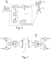
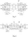
- Figures 1 and 2 illustrate, respectively, an example transceiver 100 and an example communication system 200 comprising two identical or similar transceivers.
- the example transceiver 100 is part of a network node 101.
- the transceiver 100 is adapted to use a communication channel 201 to simultaneously transmit a first signal to an other transceiver and receive a second signal from the other transceiver, wherein the first and second signals have equal carrier frequencies and different polarizations.
- the first and second signals typically need to be isolated from each other, which may be achieved by any suitable approach (e.g. polarization duplexing, digital or analogue cancellation).
- one transceiver receives the first signal and transmits the second signal when the other transceiver receives the second signal transmits the first signal, and vice versa.
- a communication system such as the example communication system 200
- one transceiver receives the first signal and transmits the second signal when the other transceiver receives the second signal transmits the first signal, and vice versa.
- channel characterization is achieved at both ends of a communication link
- channel characterization is only to be achieved at one end of the link.
- channel characterization is not necessarily performed at both ends of the communications link, but only at one end.
- a similar situation i.e. where only one of the nodes performs a particular task may also apply to other functions described herein.
- the transceiver 100 comprises at least one antenna 110, 110a, 210, 211, at least one transmitter module (TX) 120, 220, 221, at least one receiver module (RX) 130, 230, 231, and a mode alternator (MA) 160, 260, 261.
- the at least one antenna will be referred to hereinafter as the antenna, even though it typically comprises a system of antennas (e.g. an antenna system, an antenna array, an antenna matrix, or similar).
- the second signal is received by the antenna 110, 110a, 210, 211, processed (using any suitable approach) by at least one of the receiver modules 130, 230, 231, and output from the transceiver for further processing purposes 180, 280, 281.
- the second signal is also used to determine (using any suitable approach) a channel characterization of the communication channel 201 over which the second signal is received.
- the channel characterization may, for example, be determined by a channel estimator (CE) 150, 250, 251 of the transceiver as illustrated in Figures 1 and 2 .
- CE channel estimator
- the channel characterization is used to determine one or more transmission parameters for the first signal.
- the first signal is input to the transceiver as illustrated by 170, 270, 271 and submitted to application of the transmission parameters before being processed (using any suitable approach) by at least one of the transmitter modules 120, 220, 221 and transmitted by the antenna 110, 110a, 210, 211.
- the transmission parameters may, for example, be pre-coding coefficients applied to the first signal by a pre-coder (PC) 140, 240, 241 of the transceiver as illustrated in Figures 1 and 2 .
- PC pre-coder
- the channel estimator 150, 250, 251 may, for example, provide 191 either the channel characterization or the pre-coding coefficients to the pre-coder 140, 240, 241.
- the channel characterization is provided to a controller which determines the pre-coding coefficients and provides them to the pre-coder.
- the transceiver 100 has at least two modes of operation, wherein the polarizations used for transmission and reception, respectively, are different for different modes of operation.
- a first polarization used in transmission may differ slightly from the same first polarization used when receiving.
- the mode alternator 160, 260, 261 is adapted to alternate the mode of operation of the transceiver. This may be achieved by control signals 192 and 293 to the transmitter module(s) and receiver module(s), respectively. A few examples of mode alternation implementations will be described in the following in connection to Figures 3 and 4 .
- the alternation between different modes of operation may typically be synchronized between transmission and reception parts of the transceiver.
- a guard interval may be applied to accommodate the alternation.
- guard interval implementations will be described in the following in connection to Figures 6 and 7 .
- the mode of operation is to be alternated, a few of which will be given as example in the following. Various combinations of the examples may also be feasible. Thus, the mode may be alternated periodically or when a certain condition is fulfilled.
- the period may be static (fixed) or dynamic (variable).
- the period may, for example, be based on a coherence time (e.g. estimated, average, worst case, etc.) of the communication channel and/or on how often a deterioration of a performance metric of the transceiver is detected. If altered when a certain condition is fulfilled, the condition may be detection of a deterioration of a performance metric.
- the deterioration may be manifested as an increase or a decrease of the performance metric depending on which metric is used.
- performance metrics include channel estimation value, bit error rate (BER), signal-to-noise ratio (SNR), signal-to-interference ratio (SIR), signal-to-noise-and-interference ratio (SNIR), received signal strength indicator (RSSI), etc.
- a detection of deterioration may, for example, comprise the performance metric falling on a particular side of a performance metric threshold.
- performance metrics for quantifying performance on a system level comprise throughput or data rate in terms of packets/sec or bits/sec, spectral efficiency of transmission in terms of bits/sec/Hz, and error rate performance such as bit or block error rates. These performance metrics are directly or indirectly influenced by performance metrics mentioned above, e.g., SNR.
- the mode may be altered when a certain condition is fulfilled or when a maximum time interval (e.g. a period of a periodical mode alternation scheme) has elapsed since a previous alternation, whichever occurs first.
- a maximum time interval e.g. a period of a periodical mode alternation scheme
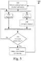
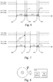
- FIGS 3 and 4 illustrate two different example implementations of the mode alternation function.
- a system 300 is shown where the two polarizations are realized using first and second transmitter modules (TX1, TX2) 320, 321, 325, 326 for the first and second polarization (illustrated by horizontal and vertical arrows in Figure 3 ), respectively, and first and receiver modules (RX1, RX2) 330, 331, 335, 336 for the first and second polarization, respectively.
- first and second transmitter modules TX1, TX2
- RX1 RX2 first and receiver modules
- the antenna 310, 311, the communication link 301, the channel estimator 350, 351, the pre-coder 340, 341, and the input/output of the transceiver 370, 371, 380, 381 are similar to the corresponding modules of Figures 1 and 2 and will not be described further here.
- the transmitter and receiver modules of different polarizations are separated by means of a polarization duplexer 315, 361 (e.g. an ortho-mode, transducer (OMT), a polarization duplexer, or similar).
- a polarization duplexer 315, 361 e.g. an ortho-mode, transducer (OMT), a polarization duplexer, or similar.
- the mode alternator comprises a signal distribution network.
- the signal distribution network is realized by switches 391, 392, 393, 394, 396, 397, 398, 399 controlled by a controller (CNTR) 360, 361 via control signals 390, 395.
- CNTR controller
- one of the transceivers (the one to the left in Figure 3 ) is in the first mode of operation and the other transceiver (the one to the right in Figure 3 ) is in the second mode of operation.
- the mode of operation is alternated for both transceivers, and transmission parameters are applied which have been determined based on channel characterizations determined during the first duration of time, and so on during subsequent durations of time.
- the first mode of operation is realized by setting the switches such that:
- the second mode of operation is realized by setting the switches such that:
- a first polarization used by a left-most transceiver during transmission may differ slightly from the same first polarization used by another, rightmost transceiver when transmitting.
- a system 400 is shown where the two polarizations are realized using (for each antenna 410, 420) first and second polarizers in the form of first and second antenna systems (e.g. realized by arrays of patch antennas) 415, 416 and 417, 418, respectively, for the first and second polarization (illustrated by horizontal and vertical arrows in Figure 4 ).
- the transmitter and receiver modules of different polarizations are separated by means of the use of the different antenna systems.
- the communication link 401, the channel estimator 450, 451, the pre-coder 440, 441, and the input/output of the transceiver 470, 471, 480, 481 are similar to the corresponding modules of Figures 1 and 2 and will not be described further here.
- the mode alternator comprises a signal distribution network.
- the signal distribution network is realized by switches 491, 492, 496, 497 controlled by a controller (CNTR) 460, 461 via control signals 490, 495.
- CNTR controller
- one of the transceivers e.g. the one to the left in Figure 4
- the other transceiver e.g. the one to the right in Figure 4
- the mode of operation is alternated for both transceivers, and transmission parameters are applied which have been determined based on channel characterizations determined during the first duration of time, and so on during subsequent durations of time.
- the first mode of operation is realized by setting the switches such that:
- the second mode of operation is realized by setting the switches such that:
- a further example of how the mode alternator may be realized builds on the disclosure of WO 2006/071153 A1 , where first and second antennas (or antenna systems) for first and second polarizations are both operatively connected to first and second polarization formers.
- the polarization formers of WO 2006/071153 A1 may be used in the context of this disclosure to construct the polarizations for reception and transmission, respectively, in the different modes of operation.
- the mode alternator comprises the polarization formers (and possibly a controller for setting parameters of the polarization formers) in this example, and no switches or connection selectors are needed.
- Another advantage with this approach is that the mode alternation may be performed very quickly since it, typically, only comprises digital baseband processing.
- Figure 5 illustrates example methods according to some embodiments.
- a method 500 may, for example, be performed by any of the transceivers described in connection to Figures 1-4 .
- the method 500 comprises using a communication channel to simultaneously transmit (step 520) a first signal to an other transceiver and receive (step 530) a second signal from the other transceiver, wherein the first and second signals have equal carrier frequencies and different polarizations.
- the first and second signals are processed (using any suitable approach) before transmission and after reception, respectively, and the second signal is used to determine (e.g. estimate, step 540) a channel characterization of the communication channel.
- the method further comprises alternating between different modes of operation of the transceiver as described above. Alteration occurrences may be periodic and/or condition based as described above. As long as the polarization (i.e. the mode of operation) is not to be alternated (No-path out from step 550), transmission and reception continues without changing transmission parameters (e.g. pre-coding coefficients). When the polarization (i.e. the mode of operation) is to be alternated (Yes-path out from step 550), however, a polarization alternation is initiated (step 560), the transmission parameters (e.g. pre-coding coefficients) are set based on the freshly determined channel characterization (step 510), and transmission and reception continues when the polarization alternation is completed.
- the transmission parameters e.g. pre-coding coefficients
- Figures 6 and 7 are schematic timing diagrams illustrating example mode alternation implementations of a first and second transceiver communicating with each other.
- the example implementation of Figure 6 may be used whether or not there is time synchronization between the two transceivers, while the example implementation of Figure 7 typically requires time synchronization between the two transceivers.
- one transceiver say transceiver A, initially transmits (TXA) 610 using the first polarization and receives (RXA) 620 using the second polarization while the other transceiver, say transceiver B, initially transmits (TXB) 630 using the second polarization and receives (RXB) 640 using the first polarization.
- Transceiver A wants to initiate a mode alternation (e.g. due to a detected performance deterioration, because a timer indicates that a maximum time interval has elapsed since a previous mode alternation, or any other reason as exemplified herein). Thus, at time 660, the transceiver A initiates a mode alternation by stopping the transmission (610).
- the transceiver B After some time 650 has passed (typically the transfer delay time between transceiver A and transceiver B), at time 661, the transceiver B detects interruption in the received signal (640) due to the stopping of transmission at transceiver A and interprets the interruption as initiation of a mode alternation. Therefore, transceiver B alternates its mode of operation by switching polarization between transmission and reception (630, 640). The mode alternation includes a minor switching time 651. At time 662, the transceiver B has alternated its mode of operation and continues transmission and reception (although there is currently no signal to receive) according to the new mode.
- the transceiver A After some time 652 has passed (typically the transfer delay time between transceiver B and transceiver A), at time 663, the transceiver A detects interruption in the received signal (620) due to the minor switching time at transceiver B and interprets the interruption as the transceiver B having performed the mode alternation. Therefore, transceiver A alternates its mode of operation by switching polarization between transmission and reception (610, 620).
- the mode alternation typically includes a minor switching time 653 (which is preferably not longer than the switching time 651).
- the transceiver A has also alternated its mode of operation and may resume transmission 610.
- one transceiver say transceiver A, initially transmits (TXA) 710 using the first polarization and receives (RXA) 720 using the second polarization while the other transceiver, say transceiver B, initially transmits (TXB) 730 using the second polarization and receives (RXB) 740 using the first polarization.
- Transceiver B wants to initiate a mode alternation (e.g. due to a detected performance deterioration, because a timer indicates that a maximum time interval has elapsed since a previous mode alternation, or any other reason as exemplified herein).
- the transceiver B initiates a mode alternation by transmitting a mode alternation notification 770 indicative of a mode alternation initiation time 762 to the transceiver A.
- the transceiver A After some time 750 has passed (typically the transfer delay time between transceiver B and transceiver A), at time 761, the transceiver A receives the mode alternation notification 770 and interprets it as an initiation of a mode alternation.
- both transceivers stop their transmissions (710, 730).
- both transceivers A and B detect interruptions in the received signal (720, 40) due to the stopping of transmission at the other transceiver and interprets the interruption as an indication that it is safe to perform the mode alternation by switching polarization between transmission and reception (710, 720 and 730, 740).
- the mode alternation typically includes a minor switching time 753.
- both transceivers have alternated their mode of operation and resume transmission and continue reception (although there are initially no signals to receive) according to the new mode.
- the guard interval may be defined as the time between times 660 and 664 for transceiver A (approximately twice the transfer delay time) and as the time between times 661 and 662 for transceiver B (approximately 0).
- the guard interval may be defined as the time between times 762 and 764 for both transceivers (approximately the transfer delay time).
- transmit buffering requirements may be lowered when some embodiments are applied.
- the buffering requirements are set by the (maximum) length of the guard interval as opposed to the switching frequency in a traditional TDD approach.
- buffering needs to accommodate the transmission data during the time 660-664.
- buffering needs to accommodate the transmission data during the time 762-764.
- DSP digital signal processors
- CPU central processing units
- FPGA field-programmable gate arrays
- ASIC application-specific integrated circuits
- Embodiments may appear within an electronic apparatus (such as a wireless communication device or a network node) comprising circuitry/logic or performing methods according to any of the embodiments.
- an electronic apparatus such as a wireless communication device or a network node
- a computer program product comprises a computer readable medium.
- the computer-readable medium may for example be a non-transitory computer-readable medium such as, for example, a flash memory, or a read-only memory (ROM) (such as the CD-ROM 800 illustrated in Figure 8 ).
- the computer readable medium may have stored thereon a computer program comprising program instructions.
- the computer program may be loadable into a data-processing unit (PROC) 820, which may, for example, be comprised in a network node 810.
- PROC data-processing unit
- MEM memory
- the computer program may, when loaded into and run by the data-processing unit, cause the data-processing unit to execute method steps according to, for example, the method shown in Figure 5 .
Landscapes
- Engineering & Computer Science (AREA)
- Computer Networks & Wireless Communication (AREA)
- Signal Processing (AREA)
- Mobile Radio Communication Systems (AREA)
Claims (15)
- Émetteur-récepteur pour un noeud de communication (101) adapté pour transmettre un premier signal à un autre noeud de communication et recevoir un second signal provenant de l'autre noeud de communication, l'émetteur-récepteur comprenant :au moins une antenne (110, 110a, 210, 211, 310, 311, 410, 411) adaptée pour transmettre simultanément le premier signal et recevoir le second signal, dans lequel le premier et le second signal de fréquence porteuse ont des fréquences porteuses égales et des polarisations différentes, dans lequel le second signal sert à déterminer une caractérisation de canal (191) d'un canal de communication via lequel le second signal est reçu et dans lequel la caractérisation de canal sert à la détermination des paramètres de transmission pour le premier signal ;au moins un module d'émetteur (120, 220, 221, 320, 325, 326, 420, 421) adapté pour traiter le premier signal avant la transmission par au moins une antenne ;au moins un module de récepteur (130, 230, 231, 330, 331, 335, 336, 430, 431) adapté pour traiter le second signal après la réception par au moins une antenne ; etun alternateur de mode (160, 260, 261, 360, 361, 460, 461) adapté pour alterner un mode de fonctionnement de l'émetteur-récepteur entre au moins un premier et un second mode de fonctionnement, dans lequel :- le premier mode de fonctionnement comprend l'émission par l'émetteur-récepteur du premier signal en utilisant une première polarisation et la réception du second signal en utilisant une seconde polarisation ; et- le second mode de fonctionnement comprend l'émission par l'émetteur-récepteur du premier signal en utilisant une troisième polarisation et la réception du signal en utilisant une quatrième polarisation ;l'émetteur-récepteur étant caractérisé en ce queau moins un module de récepteur est adapté pour détecter l'interruption du second signal reçu et interpréter l'interruption comme l'amorce d'une alternance du mode de fonctionnement (640, 661) ; etl'alternateur de mode est adapté pour alterner le mode de fonctionnement en réponse à la détection de l'interruption (630, 640, 662).
- Émetteur-récepteur selon la revendication 1, dans lequel un ou plusieurs paramètres de transmission comprennent des coefficients de décodage, l'émetteur-récepteur comprenant en outre :un estimateur de canal (150, 250, 251, 350, 351, 450, 451) adapté pour fournir la caractérisation de canal sur la base du second signal traité ; etun pré codeur (140, 240, 241, 340, 341, 440, 441) adapté pour appliquer des coefficients de décodage au premier signal avant le traitement par au moins un module d'émetteur.
- Émetteur-récepteur selon une quelconque des revendications 1 à 2, dans lequel le la troisième polarisation équivaut à la seconde polarisation et la quatrième polarisation équivaut à la première polarisation.
- Émetteur-récepteur selon la revendication 3, dans lequel :au moins un module d'émetteur comprend un premier module d'émetteur (320, 321) adapté pour traiter le premier signal selon la première polarisation et un second module d'émetteur (325, 326) adapté pour traiter le premier signal selon la seconde polarisation ;au moins un module récepteur comprend un premier module de récepteur (330, 331) adapté pour traiter le second signal selon la première polarisation et un second module de récepteur (335, 336) adapté pour traiter le second signal selon la seconde polarisation ; etl'alternateur de mode comprend un réseau de distribution de signal (391, 392, 393, 394, 396, 397, 398, 399) adapté pour :- pendant une première durée temporelle, appliquer le premier mode de fonctionnement en connectant opérationnellement au moins une antenne au premier module d'émetteur et au second module de récepteur et en causant la détermination de la caractérisation de canal sur la base d'une sortie du second module de récepteur ; et- pendant une seconde durée temporelle, appliquer le second mode de fonctionnement en connectant opérationnellement au moins une antenne au second module d'émetteur et au premier module de récepteur et en causant l'application d'un ou plusieurs paramètres de transmission au premier signal dans lequel le ou les paramètres de transmission sont déterminés sur la base de la caractérisation de canal déterminée pendant la première durée temporelle.
- Émetteur-récepteur selon la revendication 4, dans lequel l'alternateur de mode est adapté pour connecter au moins une antenne au premier et second module d'émetteur et au premier et second module de récepteur via un duplexeur de polarisation (315, 316).
- Émetteur-récepteur selon la revendication 3, dans lequel :au moins une antenne comprend un premier système d'antenne (415, 417) adapté pour émettre et recevoir des signaux selon la première polarisation et un second système d'antenne (416, 418) adaptée pour émettre et recevoir des signaux selon la seconde polarisation ; etl'alternateur de mode comprend un réseau de distribution de signal (491, 492, 496, 497) adapté pour :- pendant une première durée temporelle, appliquer le premier mode de fonctionnement en connectant opérationnellement le premier système d'antenne à au moins un module d'émetteur et en connectant opérationnellement le second système d'antenne à au moins un module de récepteur et en causant la détermination de la caractérisation de canal sur la base d'une sortie d'au moins un module de récepteur ; et- pendant une seconde durée temporelle, appliquer le second mode de fonctionnement en connectant opérationnellement le premier système d'antenne à au moins un module de récepteur et en connectant opérationnellement le second système d'antenne à au moins un module d'émetteur et en causant l'application du ou des paramètres de transmission au premier signal dans lequel le ou les paramètres de transmission sont déterminés sur la base de la caractérisation de canal déterminé pendant la première durée temporelle.
- Émetteur-récepteur selon une quelconque des revendications 1 à 6, dans lequel :au moins un module d'émetteur est adapté pour arrêter la transmission du premier signal afin d'amorcer l'alternance du mode de fonctionnement (610, 660) ;au moins un module de récepteur est adapté pour détecter l'interruption du second signal reçu après que la transmission du premier signal a été arrêtée (620, 663) ;l'alternateur de mode est adapté pour alterner le mode de fonctionnement en réponse à la détection de l'interruption (610, 620, 653) ; etau moins un module d'émetteur est adapté pour reprendre la transmission du premier signal après que le mode de fonctionnement a été alterné (610, 664).
- Émetteur-récepteur selon une quelconque des revendications 1 à 7, dans lequel le noeud de communication et l'autre noeud de communication sont synchronisées temporellement et dans lequel une notification d'alternance de mode (770) communiquée entre le noeud de communication et l'autre noeud de communication est adapté pour amorcer une alternance du mode de fonctionnement et indique une condition d'amorce d'alternance de mode (762).
- Émetteur-récepteur selon la revendication 8, dans lequel :au moins un module de récepteur est adapté pour recevoir la notification d'alternance de mode depuis l'autre noeud (720, 761) ;au moins un module d'émetteur est adapté pour arrêter la transmission du premier signal lorsque la condition d'amorce d'alternance de mode est remplie (710, 762) ;au moins un module de récepteur est adapté pour détecter l'interruption du second signal reçu après que la condition d'amorce d'alternance de mode est remplie (720, 763) ;l'alternateur de mode est adaptée pour alterner le mode de fonctionnement en réponse à la détection de l'interruption (710, 720, 753) ; etau moins un module d'émetteur est adapté pour reprendre la transmission du premier signal après que le mode de fonctionnement a été alterné (710, 764).
- Émetteur-récepteur selon une quelconque des revendications 8 à 9, dans lequel :au moins un module d'émetteur est adapté pour transmettre la notification d'alternance de mode à l'autre noeud (730, 760) ;au moins un module d'émetteur est adapté pour arrêter la transmission du premier signal lorsque la condition d'amorce d'alternance de mode est remplie (730, 762) ;au moins un module de récepteur est adapté pour détecter l'interruption du second signal reçu après que la condition d'amorce alternance de mode est remplie (740, 763) ;l'alternateur de mode est adapté pour alterner le mode de fonctionnement en réponse à la détection de l'interruption (730, 740, 753) ; etau moins un module d'émetteur est adapté pour reprendre la transmission du premier signal après que le mode de fonctionnement a été alterné (730, 764).
- Émetteur-récepteur selon une quelconque des revendications 1 à 10, dans lequel au moins un module d'émetteur est adapté pour interrompre la transmission du premier signal pendant un intervalle de garde en association avec le l'alternateur de mode alternant le mode de fonctionnement.
- Noeud de communication comprenant l'émetteur-récepteur selon une quelconque des revendications 1 à 11.
- Système de communication comprenant deux émetteur-récepteur selon une quelconque des revendications 1 à 11.
- Procédé d'un émetteur-récepteur pour un noeud de communication adapté pour transmettre un premier signal vers un autre noeud de communication et recevoir un second signal provenant de l'autre noeud de communication le procédé comprenant de : transmettre simultanément (520) le premier signal et recevoir (530) le second signal via au moins une antenne, dans lequel le premier et le second signal sont de fréquence porteuse égales et de polarisations différentes, dans lequel le second signal sert à déterminer une caractérisation de canal d'un canal de communication via lequel le second signal est reçu et dans lequel la caractérisation de canal sert à la détermination des paramètres de transmission pour le premier signal ;
traiter le premier signal par au moins un module d'émetteur avant la transmission par au moins une antenne ;
traiter le second signal par au moins un module de récepteur après la réception par au moins une antenne ; et
alterner (560) un mode de fonctionnement de l'émetteur-récepteur entre au moins un premier et un second mode de fonctionnement, dans lequel :- le premier mode de fonctionnement comprend l'émission par l'émetteur-récepteur du premier signal en utilisant une première polarisation et la réception du second signal en utilisant une seconde polarisation ; et- le second mode de fonctionnement comprend l'émission par l'émetteur-récepteur du premier signal en utilisant une troisième polarisation et la réception du signal en utilisant une quatrième polarisation ;le procédé étant caractérisé en ce que alterner le mode de fonctionnement comprend de :détecter l'interruption du second signal reçu et interpréter l'interruption comme l'amorce d'une alternance du mode de fonctionnement ; etalterner le mode de fonctionnement en réponse à la détection de l'interruption. - Produit de programme informatique comprenant un support lisible par ordinateur (800), renfermant un programme informatique comprenant des instructions de programme, le programme informatique étant chargeable dans une unité de traitement de données (820) et adapté pour causer l'exécution du procédé selon la revendication 14 lorsque le programme informatique est exécuté par l'unité de traitement de données.
Applications Claiming Priority (1)
| Application Number | Priority Date | Filing Date | Title |
|---|---|---|---|
| PCT/EP2015/061795 WO2016188575A1 (fr) | 2015-05-28 | 2015-05-28 | Émetteur-récepteur à mode de fonctionnement alternatif |
Publications (2)
| Publication Number | Publication Date |
|---|---|
| EP3304766A1 EP3304766A1 (fr) | 2018-04-11 |
| EP3304766B1 true EP3304766B1 (fr) | 2019-03-13 |
Family
ID=53267380
Family Applications (1)
| Application Number | Title | Priority Date | Filing Date |
|---|---|---|---|
| EP15724696.8A Active EP3304766B1 (fr) | 2015-05-28 | 2015-05-28 | Émetteur-récepteur à mode de fonctionnement alternatif |
Country Status (3)
| Country | Link |
|---|---|
| US (1) | US10284252B2 (fr) |
| EP (1) | EP3304766B1 (fr) |
| WO (1) | WO2016188575A1 (fr) |
Families Citing this family (1)
| Publication number | Priority date | Publication date | Assignee | Title |
|---|---|---|---|---|
| US12057964B1 (en) * | 2023-02-02 | 2024-08-06 | Geotab Inc. | Methods and devices for detecting a controller area network connection on a universal serial bus port |
Family Cites Families (10)
| Publication number | Priority date | Publication date | Assignee | Title |
|---|---|---|---|---|
| US6512480B1 (en) * | 2001-08-20 | 2003-01-28 | Vectrad Networks Corp. | System and method for narrow beam antenna diversity in an RF data transmission system |
| US7003058B2 (en) | 2002-02-27 | 2006-02-21 | The Boeing Company | Polarization division duplexing with cross polarization interference canceller |
| US20060087385A1 (en) * | 2004-10-22 | 2006-04-27 | Time Domain Corporation | System and method for duplex operation using a hybrid element |
| CN101091285B (zh) | 2004-12-30 | 2012-10-03 | Lm爱立信电话有限公司 | 用于蜂窝电话系统中的无线电基站的天线装置 |
| JP5003391B2 (ja) * | 2007-10-01 | 2012-08-15 | 富士通株式会社 | 光伝送システムおよび光伝送方法 |
| CN101800678B (zh) * | 2010-03-12 | 2012-05-23 | 华为技术有限公司 | 应用ccdp和xpic的微波传输方法、装置和系统 |
| US8422540B1 (en) | 2012-06-21 | 2013-04-16 | CBF Networks, Inc. | Intelligent backhaul radio with zero division duplexing |
| US9520914B2 (en) * | 2012-06-25 | 2016-12-13 | Samsung Electronics Co., Ltd. | Full-duplex wireless communication system using polarization |
| WO2014202156A1 (fr) | 2013-06-18 | 2014-12-24 | Telefonaktiebolaget L M Ericsson (Publ) | Annulation de fuite pour émetteur-récepteur entrée multiple sortie multiple |
| US9832666B2 (en) * | 2014-12-19 | 2017-11-28 | Intel Corporation | Device and method for self-interference cancellation |
-
2015
- 2015-05-28 EP EP15724696.8A patent/EP3304766B1/fr active Active
- 2015-05-28 WO PCT/EP2015/061795 patent/WO2016188575A1/fr not_active Ceased
- 2015-05-28 US US15/576,392 patent/US10284252B2/en active Active
Non-Patent Citations (1)
| Title |
|---|
| None * |
Also Published As
| Publication number | Publication date |
|---|---|
| WO2016188575A1 (fr) | 2016-12-01 |
| US10284252B2 (en) | 2019-05-07 |
| US20180159586A1 (en) | 2018-06-07 |
| EP3304766A1 (fr) | 2018-04-11 |
Similar Documents
| Publication | Publication Date | Title |
|---|---|---|
| CN109391962B (zh) | 通信方法及通信装置 | |
| CA3185386A1 (fr) | Signalisation pour aider a une retroaction de csi de type ii nr amelioree | |
| US20160202344A1 (en) | Location reporting for extremely high frequency (ehf) devices | |
| US20160149633A1 (en) | Technique for obtaining the rotation of a wireless device | |
| US10873871B2 (en) | Path selection for fine timing measurement protocol | |
| US10911127B2 (en) | Beam management of a radio transceiver device | |
| CN111919393B (zh) | 包括控制电路的装置、操作装置的方法 | |
| WO2011160372A1 (fr) | Procédé et système d'étalonnage d'antennes sur la base d'une émission coordonnée en tdd à points multiples | |
| US20190129024A1 (en) | Path selection for fine timing measurement protocol | |
| EP3981090A1 (fr) | Étalonnage pour des éléments d'antenne d'une structure à antennes multiples | |
| WO2020182046A1 (fr) | Procédé de mesure de signal de référence et appareil de communication | |
| EP2050206B1 (fr) | Dispositif pour améliorer les caractéristiques d'isolation dans un système de télécommunications | |
| CN111052814B (zh) | 客户端设备、网络接入节点及其方法 | |
| EP3304766B1 (fr) | Émetteur-récepteur à mode de fonctionnement alternatif | |
| US20140219144A1 (en) | Method and aparatus for controlling performance in a radio node | |
| US9853800B2 (en) | Method and radio node for controlling change of communication mode | |
| AU2018409506B2 (en) | Signal strength scaling of an uplink measurement signal and corresponding uplink transmission beam according to an estimated interference level | |
| US20210084657A1 (en) | Methods, network nodes, and computer programs for transmit timing adjustment | |
| EP4402950A1 (fr) | Protection contre la surchauffe et prévention/atténuation d'une consommation d'énergie excessive de dispositif sans fil | |
| JP2024047097A (ja) | 複数のアクセスポイント装置を介して無線デバイスと通信する処理装置 | |
| WO2024165612A1 (fr) | Configuration de mesure de trs à rafales multiples | |
| WO2025208598A1 (fr) | Procédé de mesure et de signalement d'informations d'état de canal (csi) et dispositif de communication sans fil | |
| CN120419123A (zh) | 通信系统中的带宽部分切换 |
Legal Events
| Date | Code | Title | Description |
|---|---|---|---|
| STAA | Information on the status of an ep patent application or granted ep patent |
Free format text: STATUS: THE INTERNATIONAL PUBLICATION HAS BEEN MADE |
|
| PUAI | Public reference made under article 153(3) epc to a published international application that has entered the european phase |
Free format text: ORIGINAL CODE: 0009012 |
|
| STAA | Information on the status of an ep patent application or granted ep patent |
Free format text: STATUS: REQUEST FOR EXAMINATION WAS MADE |
|
| 17P | Request for examination filed |
Effective date: 20171122 |
|
| AK | Designated contracting states |
Kind code of ref document: A1 Designated state(s): AL AT BE BG CH CY CZ DE DK EE ES FI FR GB GR HR HU IE IS IT LI LT LU LV MC MK MT NL NO PL PT RO RS SE SI SK SM TR |
|
| AX | Request for extension of the european patent |
Extension state: BA ME |
|
| DAV | Request for validation of the european patent (deleted) | ||
| DAX | Request for extension of the european patent (deleted) | ||
| GRAP | Despatch of communication of intention to grant a patent |
Free format text: ORIGINAL CODE: EPIDOSNIGR1 |
|
| STAA | Information on the status of an ep patent application or granted ep patent |
Free format text: STATUS: GRANT OF PATENT IS INTENDED |
|
| INTG | Intention to grant announced |
Effective date: 20181205 |
|
| GRAS | Grant fee paid |
Free format text: ORIGINAL CODE: EPIDOSNIGR3 |
|
| GRAA | (expected) grant |
Free format text: ORIGINAL CODE: 0009210 |
|
| STAA | Information on the status of an ep patent application or granted ep patent |
Free format text: STATUS: THE PATENT HAS BEEN GRANTED |
|
| AK | Designated contracting states |
Kind code of ref document: B1 Designated state(s): AL AT BE BG CH CY CZ DE DK EE ES FI FR GB GR HR HU IE IS IT LI LT LU LV MC MK MT NL NO PL PT RO RS SE SI SK SM TR |
|
| REG | Reference to a national code |
Ref country code: GB Ref legal event code: FG4D |
|
| REG | Reference to a national code |
Ref country code: CH Ref legal event code: EP Ref country code: AT Ref legal event code: REF Ref document number: 1109104 Country of ref document: AT Kind code of ref document: T Effective date: 20190315 |
|
| REG | Reference to a national code |
Ref country code: IE Ref legal event code: FG4D |
|
| REG | Reference to a national code |
Ref country code: DE Ref legal event code: R096 Ref document number: 602015026321 Country of ref document: DE |
|
| REG | Reference to a national code |
Ref country code: NL Ref legal event code: FP |
|
| REG | Reference to a national code |
Ref country code: LT Ref legal event code: MG4D |
|
| PG25 | Lapsed in a contracting state [announced via postgrant information from national office to epo] |
Ref country code: SE Free format text: LAPSE BECAUSE OF FAILURE TO SUBMIT A TRANSLATION OF THE DESCRIPTION OR TO PAY THE FEE WITHIN THE PRESCRIBED TIME-LIMIT Effective date: 20190313 Ref country code: LT Free format text: LAPSE BECAUSE OF FAILURE TO SUBMIT A TRANSLATION OF THE DESCRIPTION OR TO PAY THE FEE WITHIN THE PRESCRIBED TIME-LIMIT Effective date: 20190313 Ref country code: FI Free format text: LAPSE BECAUSE OF FAILURE TO SUBMIT A TRANSLATION OF THE DESCRIPTION OR TO PAY THE FEE WITHIN THE PRESCRIBED TIME-LIMIT Effective date: 20190313 Ref country code: NO Free format text: LAPSE BECAUSE OF FAILURE TO SUBMIT A TRANSLATION OF THE DESCRIPTION OR TO PAY THE FEE WITHIN THE PRESCRIBED TIME-LIMIT Effective date: 20190613 |
|
| PG25 | Lapsed in a contracting state [announced via postgrant information from national office to epo] |
Ref country code: GR Free format text: LAPSE BECAUSE OF FAILURE TO SUBMIT A TRANSLATION OF THE DESCRIPTION OR TO PAY THE FEE WITHIN THE PRESCRIBED TIME-LIMIT Effective date: 20190614 Ref country code: RS Free format text: LAPSE BECAUSE OF FAILURE TO SUBMIT A TRANSLATION OF THE DESCRIPTION OR TO PAY THE FEE WITHIN THE PRESCRIBED TIME-LIMIT Effective date: 20190313 Ref country code: BG Free format text: LAPSE BECAUSE OF FAILURE TO SUBMIT A TRANSLATION OF THE DESCRIPTION OR TO PAY THE FEE WITHIN THE PRESCRIBED TIME-LIMIT Effective date: 20190613 Ref country code: LV Free format text: LAPSE BECAUSE OF FAILURE TO SUBMIT A TRANSLATION OF THE DESCRIPTION OR TO PAY THE FEE WITHIN THE PRESCRIBED TIME-LIMIT Effective date: 20190313 Ref country code: HR Free format text: LAPSE BECAUSE OF FAILURE TO SUBMIT A TRANSLATION OF THE DESCRIPTION OR TO PAY THE FEE WITHIN THE PRESCRIBED TIME-LIMIT Effective date: 20190313 |
|
| REG | Reference to a national code |
Ref country code: AT Ref legal event code: MK05 Ref document number: 1109104 Country of ref document: AT Kind code of ref document: T Effective date: 20190313 |
|
| PG25 | Lapsed in a contracting state [announced via postgrant information from national office to epo] |
Ref country code: RO Free format text: LAPSE BECAUSE OF FAILURE TO SUBMIT A TRANSLATION OF THE DESCRIPTION OR TO PAY THE FEE WITHIN THE PRESCRIBED TIME-LIMIT Effective date: 20190313 Ref country code: IT Free format text: LAPSE BECAUSE OF FAILURE TO SUBMIT A TRANSLATION OF THE DESCRIPTION OR TO PAY THE FEE WITHIN THE PRESCRIBED TIME-LIMIT Effective date: 20190313 Ref country code: CZ Free format text: LAPSE BECAUSE OF FAILURE TO SUBMIT A TRANSLATION OF THE DESCRIPTION OR TO PAY THE FEE WITHIN THE PRESCRIBED TIME-LIMIT Effective date: 20190313 Ref country code: AL Free format text: LAPSE BECAUSE OF FAILURE TO SUBMIT A TRANSLATION OF THE DESCRIPTION OR TO PAY THE FEE WITHIN THE PRESCRIBED TIME-LIMIT Effective date: 20190313 Ref country code: SK Free format text: LAPSE BECAUSE OF FAILURE TO SUBMIT A TRANSLATION OF THE DESCRIPTION OR TO PAY THE FEE WITHIN THE PRESCRIBED TIME-LIMIT Effective date: 20190313 Ref country code: PT Free format text: LAPSE BECAUSE OF FAILURE TO SUBMIT A TRANSLATION OF THE DESCRIPTION OR TO PAY THE FEE WITHIN THE PRESCRIBED TIME-LIMIT Effective date: 20190713 Ref country code: ES Free format text: LAPSE BECAUSE OF FAILURE TO SUBMIT A TRANSLATION OF THE DESCRIPTION OR TO PAY THE FEE WITHIN THE PRESCRIBED TIME-LIMIT Effective date: 20190313 Ref country code: EE Free format text: LAPSE BECAUSE OF FAILURE TO SUBMIT A TRANSLATION OF THE DESCRIPTION OR TO PAY THE FEE WITHIN THE PRESCRIBED TIME-LIMIT Effective date: 20190313 |
|
| PG25 | Lapsed in a contracting state [announced via postgrant information from national office to epo] |
Ref country code: SM Free format text: LAPSE BECAUSE OF FAILURE TO SUBMIT A TRANSLATION OF THE DESCRIPTION OR TO PAY THE FEE WITHIN THE PRESCRIBED TIME-LIMIT Effective date: 20190313 Ref country code: PL Free format text: LAPSE BECAUSE OF FAILURE TO SUBMIT A TRANSLATION OF THE DESCRIPTION OR TO PAY THE FEE WITHIN THE PRESCRIBED TIME-LIMIT Effective date: 20190313 |
|
| REG | Reference to a national code |
Ref country code: DE Ref legal event code: R097 Ref document number: 602015026321 Country of ref document: DE |
|
| REG | Reference to a national code |
Ref country code: CH Ref legal event code: PL |
|
| PG25 | Lapsed in a contracting state [announced via postgrant information from national office to epo] |
Ref country code: IS Free format text: LAPSE BECAUSE OF FAILURE TO SUBMIT A TRANSLATION OF THE DESCRIPTION OR TO PAY THE FEE WITHIN THE PRESCRIBED TIME-LIMIT Effective date: 20190713 Ref country code: AT Free format text: LAPSE BECAUSE OF FAILURE TO SUBMIT A TRANSLATION OF THE DESCRIPTION OR TO PAY THE FEE WITHIN THE PRESCRIBED TIME-LIMIT Effective date: 20190313 |
|
| PLBE | No opposition filed within time limit |
Free format text: ORIGINAL CODE: 0009261 |
|
| STAA | Information on the status of an ep patent application or granted ep patent |
Free format text: STATUS: NO OPPOSITION FILED WITHIN TIME LIMIT |
|
| PG25 | Lapsed in a contracting state [announced via postgrant information from national office to epo] |
Ref country code: LI Free format text: LAPSE BECAUSE OF NON-PAYMENT OF DUE FEES Effective date: 20190531 Ref country code: CH Free format text: LAPSE BECAUSE OF NON-PAYMENT OF DUE FEES Effective date: 20190531 Ref country code: MC Free format text: LAPSE BECAUSE OF FAILURE TO SUBMIT A TRANSLATION OF THE DESCRIPTION OR TO PAY THE FEE WITHIN THE PRESCRIBED TIME-LIMIT Effective date: 20190313 Ref country code: DK Free format text: LAPSE BECAUSE OF FAILURE TO SUBMIT A TRANSLATION OF THE DESCRIPTION OR TO PAY THE FEE WITHIN THE PRESCRIBED TIME-LIMIT Effective date: 20190313 |
|
| REG | Reference to a national code |
Ref country code: BE Ref legal event code: MM Effective date: 20190531 |
|
| 26N | No opposition filed |
Effective date: 20191216 |
|
| PG25 | Lapsed in a contracting state [announced via postgrant information from national office to epo] |
Ref country code: SI Free format text: LAPSE BECAUSE OF FAILURE TO SUBMIT A TRANSLATION OF THE DESCRIPTION OR TO PAY THE FEE WITHIN THE PRESCRIBED TIME-LIMIT Effective date: 20190313 Ref country code: LU Free format text: LAPSE BECAUSE OF NON-PAYMENT OF DUE FEES Effective date: 20190528 |
|
| PG25 | Lapsed in a contracting state [announced via postgrant information from national office to epo] |
Ref country code: TR Free format text: LAPSE BECAUSE OF FAILURE TO SUBMIT A TRANSLATION OF THE DESCRIPTION OR TO PAY THE FEE WITHIN THE PRESCRIBED TIME-LIMIT Effective date: 20190313 |
|
| PG25 | Lapsed in a contracting state [announced via postgrant information from national office to epo] |
Ref country code: IE Free format text: LAPSE BECAUSE OF NON-PAYMENT OF DUE FEES Effective date: 20190528 |
|
| PG25 | Lapsed in a contracting state [announced via postgrant information from national office to epo] |
Ref country code: BE Free format text: LAPSE BECAUSE OF NON-PAYMENT OF DUE FEES Effective date: 20190531 |
|
| PG25 | Lapsed in a contracting state [announced via postgrant information from national office to epo] |
Ref country code: FR Free format text: LAPSE BECAUSE OF NON-PAYMENT OF DUE FEES Effective date: 20190531 |
|
| PG25 | Lapsed in a contracting state [announced via postgrant information from national office to epo] |
Ref country code: CY Free format text: LAPSE BECAUSE OF FAILURE TO SUBMIT A TRANSLATION OF THE DESCRIPTION OR TO PAY THE FEE WITHIN THE PRESCRIBED TIME-LIMIT Effective date: 20190313 |
|
| PG25 | Lapsed in a contracting state [announced via postgrant information from national office to epo] |
Ref country code: MT Free format text: LAPSE BECAUSE OF FAILURE TO SUBMIT A TRANSLATION OF THE DESCRIPTION OR TO PAY THE FEE WITHIN THE PRESCRIBED TIME-LIMIT Effective date: 20190313 Ref country code: HU Free format text: LAPSE BECAUSE OF FAILURE TO SUBMIT A TRANSLATION OF THE DESCRIPTION OR TO PAY THE FEE WITHIN THE PRESCRIBED TIME-LIMIT; INVALID AB INITIO Effective date: 20150528 |
|
| PG25 | Lapsed in a contracting state [announced via postgrant information from national office to epo] |
Ref country code: MK Free format text: LAPSE BECAUSE OF FAILURE TO SUBMIT A TRANSLATION OF THE DESCRIPTION OR TO PAY THE FEE WITHIN THE PRESCRIBED TIME-LIMIT Effective date: 20190313 |
|
| PGFP | Annual fee paid to national office [announced via postgrant information from national office to epo] |
Ref country code: NL Payment date: 20250526 Year of fee payment: 11 |
|
| PGFP | Annual fee paid to national office [announced via postgrant information from national office to epo] |
Ref country code: DE Payment date: 20250529 Year of fee payment: 11 |
|
| PGFP | Annual fee paid to national office [announced via postgrant information from national office to epo] |
Ref country code: GB Payment date: 20250527 Year of fee payment: 11 |