EP3304899B1 - Autostereoskopisches system - Google Patents
Autostereoskopisches system Download PDFInfo
- Publication number
- EP3304899B1 EP3304899B1 EP16721443.6A EP16721443A EP3304899B1 EP 3304899 B1 EP3304899 B1 EP 3304899B1 EP 16721443 A EP16721443 A EP 16721443A EP 3304899 B1 EP3304899 B1 EP 3304899B1
- Authority
- EP
- European Patent Office
- Prior art keywords
- screen
- channel
- viewer
- channel mask
- filter device
- Prior art date
- Legal status (The legal status is an assumption and is not a legal conclusion. Google has not performed a legal analysis and makes no representation as to the accuracy of the status listed.)
- Not-in-force
Links
Images




Classifications
-
- G—PHYSICS
- G02—OPTICS
- G02B—OPTICAL ELEMENTS, SYSTEMS OR APPARATUS
- G02B30/00—Optical systems or apparatus for producing three-dimensional [3D] effects, e.g. stereoscopic images
- G02B30/20—Optical systems or apparatus for producing three-dimensional [3D] effects, e.g. stereoscopic images by providing first and second parallax images to an observer's left and right eyes
- G02B30/26—Optical systems or apparatus for producing three-dimensional [3D] effects, e.g. stereoscopic images by providing first and second parallax images to an observer's left and right eyes of the autostereoscopic type
- G02B30/27—Optical systems or apparatus for producing three-dimensional [3D] effects, e.g. stereoscopic images by providing first and second parallax images to an observer's left and right eyes of the autostereoscopic type involving lenticular arrays
-
- G—PHYSICS
- G02—OPTICS
- G02B—OPTICAL ELEMENTS, SYSTEMS OR APPARATUS
- G02B27/00—Optical systems or apparatus not provided for by any of the groups G02B1/00 - G02B26/00, G02B30/00
- G02B27/0012—Optical design, e.g. procedures, algorithms, optimisation routines
-
- G—PHYSICS
- G02—OPTICS
- G02B—OPTICAL ELEMENTS, SYSTEMS OR APPARATUS
- G02B27/00—Optical systems or apparatus not provided for by any of the groups G02B1/00 - G02B26/00, G02B30/00
- G02B27/0093—Optical systems or apparatus not provided for by any of the groups G02B1/00 - G02B26/00, G02B30/00 with means for monitoring data relating to the user, e.g. head-tracking, eye-tracking
-
- H—ELECTRICITY
- H04—ELECTRIC COMMUNICATION TECHNIQUE
- H04N—PICTORIAL COMMUNICATION, e.g. TELEVISION
- H04N13/00—Stereoscopic video systems; Multi-view video systems; Details thereof
- H04N13/30—Image reproducers
- H04N13/302—Image reproducers for viewing without the aid of special glasses, i.e. using autostereoscopic displays
-
- H—ELECTRICITY
- H04—ELECTRIC COMMUNICATION TECHNIQUE
- H04N—PICTORIAL COMMUNICATION, e.g. TELEVISION
- H04N13/00—Stereoscopic video systems; Multi-view video systems; Details thereof
- H04N13/30—Image reproducers
- H04N13/302—Image reproducers for viewing without the aid of special glasses, i.e. using autostereoscopic displays
- H04N13/31—Image reproducers for viewing without the aid of special glasses, i.e. using autostereoscopic displays using parallax barriers
-
- H—ELECTRICITY
- H04—ELECTRIC COMMUNICATION TECHNIQUE
- H04N—PICTORIAL COMMUNICATION, e.g. TELEVISION
- H04N13/00—Stereoscopic video systems; Multi-view video systems; Details thereof
- H04N13/30—Image reproducers
- H04N13/356—Image reproducers having separate monoscopic and stereoscopic modes
- H04N13/359—Switching between monoscopic and stereoscopic modes
-
- H—ELECTRICITY
- H04—ELECTRIC COMMUNICATION TECHNIQUE
- H04N—PICTORIAL COMMUNICATION, e.g. TELEVISION
- H04N13/00—Stereoscopic video systems; Multi-view video systems; Details thereof
- H04N13/30—Image reproducers
- H04N13/366—Image reproducers using viewer tracking
-
- H—ELECTRICITY
- H04—ELECTRIC COMMUNICATION TECHNIQUE
- H04N—PICTORIAL COMMUNICATION, e.g. TELEVISION
- H04N13/00—Stereoscopic video systems; Multi-view video systems; Details thereof
- H04N13/30—Image reproducers
- H04N13/366—Image reproducers using viewer tracking
- H04N13/38—Image reproducers using viewer tracking for tracking vertical translational head movements
-
- H—ELECTRICITY
- H04—ELECTRIC COMMUNICATION TECHNIQUE
- H04N—PICTORIAL COMMUNICATION, e.g. TELEVISION
- H04N13/00—Stereoscopic video systems; Multi-view video systems; Details thereof
- H04N13/30—Image reproducers
- H04N13/366—Image reproducers using viewer tracking
- H04N13/383—Image reproducers using viewer tracking for tracking with gaze detection, i.e. detecting the lines of sight of the viewer's eyes
-
- H—ELECTRICITY
- H04—ELECTRIC COMMUNICATION TECHNIQUE
- H04N—PICTORIAL COMMUNICATION, e.g. TELEVISION
- H04N13/00—Stereoscopic video systems; Multi-view video systems; Details thereof
- H04N13/30—Image reproducers
- H04N13/398—Synchronisation thereof; Control thereof
Definitions
- the invention relates to a method of constructing a channel mask for an autostereoscopic display, the display comprising an electronically controlled screen covered by a parallax filter device that includes a refractive medium and is configured to obscure certain areas on the screen for a left eye of a viewer and to obscure certain other areas on the screen for a right eye of the viewer, the channel mask being a two-dimensional geometric object that permits to assign to each point on the screen one of a number of viewing positions of an eye of the viewer, the channel mask dividing the surface of the screen into separate channel zones that, from a given position of the viewer, are visible by not more than one eye of the viewer, with boundaries between the channel zones being determined by corresponding features of the parallax filter device.
- an impression of spatial depth is generated by presenting to the two eyes of a viewer two different images that show the same scene from slightly different perspectives which represent the parallax difference between the left right and eye of the viewer.
- US 8 077 195 B2 describes a system which permits to view autostereoscopic images "with the naked eye", so that stereoscopic images can for example be produced on a screen of a computer monitor or the like.
- the image information of the left and right channels i. e. the information intended for the left and right eye, respectively, of the user, is displayed on the screen in the form of segments, i. e. vertical or slanted stripes, which alternatingly belong to the left and to the right channel, and a parallax filter device, e. g.
- a head tracking or eye tracking system may be employed for adapting the image representation on the screen to changing positions of the viewer.
- a channel mask is constructed in order to appropriately assign the correct channel to each pixel.
- channel masks may be extended to multi-view systems wherein the screen can be watched by one or more viewers from a number of different view positions. Then, the channel mask will define three or more channels, one for each of the envisaged viewing directions, i.e. the envisaged positions of an eye of a viewer.
- the channel masks may be defined in an object plane, i.e. the plane that forms the surface of the screen, and in a principal plane of the parallax filter, which principal plane is somewhat offset from the object plane towards the viewer(s).
- object plane i.e. the plane that forms the surface of the screen
- principal plane which principal plane is somewhat offset from the object plane towards the viewer(s).
- the principal plane may be the plane that contains the apex lines of the cylindrical lenses.
- each cylindrical lens When a viewer watches an area of the screen at right angles, one half of each cylindrical lens will deflect the light from the underlying screen pixels towards the left side of the user's face, and the other half of the lens will deflect the light of the underlying pixels towards the right side of the user's face. Consequently, the alternating pattern of apex lines of the cylindrical lenses and border lines between adjacent lenses will naturally define a channel mask in the principal plane, and a corresponding channel mask in the object plane can simply be obtained by an orthogonal projection in the direction normal to the screen.
- the channel mask in the object plane will be laterally offset relative to the channel mask in the principal plane.
- the amount of this offset will also be influenced by the refraction of the light rays at the apex of each lens.
- the effect of the refraction can be compensated with reasonable accuracy by defining an auxiliary object plane between the object plane and the principal plane, the position of this auxiliary object plane being determined by the ratio between the refractive indices of the surrounding medium (air) and of the glass forming the lens, such that the channel mask in the object plane can be obtained by a central projection of the channel mask in the principal plane onto the auxiliary object plane, with the viewing position as projection center.
- US 2009/225154 A1 discloses a 3D display wherein ray-tracing techniques have been used for verifying a lens array design.
- the channel mask is constructed by tracing light rays that propagate from selected points on the screen and are refracted at the parallax filter device, said boundaries being determined by refracted light rays that connect a reference point for the position of the viewer to said features of the parallax filter device.
- the steps of constructing a channel mask in the principal plane and then applying a central projection onto the auxiliary object plane are integrated into a single step of tracing light rays from the surface of the screen through the refractive medium of the parallax filter to a given viewing position or, equivalently, tracing back the light rays from the viewing position through the refractive medium onto the screen surface.
- the invention has the advantage that a refraction-corrected channel mask is obtained which is more accurate in particular for large skew angles. This permits to provide an autostereoscopic display with high image quality even for larger screen dimensions. Moreover, this method permits to adapt the system more easily to different types of parallax filter devices and also to displays with curved screens, for example.
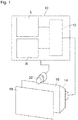
- the system shown in Fig. 1 comprises a computer system 10, e. g. a personal computer, including a graphics card 12 which drives a display 14 so as to display images on a screen 16 of the display.
- a parallax filter device e.g. a lens array 18 is disposed in front of the screen 16, and a video camera forming part of an eye tracking or head tracking system 20 is attached to the display 14 and communicates with the computer system 10.
- the graphics card 12 has access to two texture maps L and R that are stored in a memory of the computer system 10.
- the texture map L stores image information of a left channel, i. e. image information that is to be displayed to the left eye of a user (not shown) who looks at the screen 16 through the lens array 18.
- the texture map R stores image information of the right channel for the right eye of the user.
- the head tracking system 20 keeps track of any movements of the head of the user and signals these movements to the computer system, which will then adapt the information displayed on the screen 16 to the changed position of the user.
- Fig. 2 is a schematic perspective view showing a part of the lens array 18 and a part of the screen 16.
- the surface of the screen 16 is divided into an array of individually controllable light emitting pixels 22.
- the pixels 22 will actually be sub-pixels in the basic colors red, green and blue.
- the lens array 18 is constituted by a layer of glass or another transparent refractive medium and has a large number of cylindrical lenses 24 disposed in parallel and side-by-side.
- the cylindrical lenses 24 either extend approximately in vertical direction of the screen or may be inclined relative to the vertical and, accordingly, relative to the raster of the pixels 22 on the screen.
- the cylindrical lenses 24 are also shown to be slightly curved. This may be due to manufacturing tolerances, or the curvature may have been formed on purpose e.g. in order to further reduce Moiré effects resulting from a superposition of the regular lens raster on an also regular pixel raster.
- the width of the cylindrical lenses 24 is typically an integer or fractional multiple, of the width of an individual sub-pixel, typically at least three times its width.
- Each cylindrical lens has an apex line 26 shown as a dashed line in Fig. 2 .
- FIG. 2 Right and left eyes 28, 30 of a viewer have been shown schematically in Fig. 2 .
- Two light rays 32, 34 have been shown to symbolize light that is emitted from two neighboring pixels 22 on the screen 16, is collimated by one of the cylindrical lenses 24 and deflected to the right eye and the left eye, respectively, of the user.
- the distance between the top surface of the lens array 18 and the surface of the screen 16 may be equal to, smaller or even larger than the focal length of the lenses 24, so that each eye will see an enlarged image of a corresponding pixel or parts thereof.
- Fig. 3 is a cross-sectional view of two of the cylindrical lenses 24.
- a top surface of the screen 16 is designated as an object plane o of the lens array, and the plane passing through the apex lines 26 of the lenses 24 is designated as a principal plane p.
- the screen 16 is viewed at rights angles, i.e. from a position on a normal to the screen, light that is emitted from a part of the screen below the left half of a lens 24 will be deflected towards the left eye of the viewer, as is symbolized by rays 34 in Fig.
- a channel mask Mo can be defined which divides the surface of the screen 16 into left channel zones 36 that are visible only by the left eye (or are not visible at all) and right channel zones 38 that are visible only by the right eye (or not visible at all).
- a first-type boundary between the zones 36, 38 corresponds to the position of the apex of a lens 24, and a second-type boundary 42 corresponds to the boundary between two adjacent lenses 24. Since, thus, the channel mask is defined by the geometry of the lens array 18, it is convenient to consider a channel mask Mp in the principal plane. When the pertinent part of the screen 16 is watched at right angles, as in Fig. 3 , the channel masks Mp and Mo are congruent.
- Fig. 4 illustrates a situation where the part of the screen 16 is seen by a viewer under a certain skew angle ⁇ . More precisely, Fig. 4 shows rays 44 which each connect the reference point U ( Fig. 2 ) to an apex of one of the lenses 24. It is assumed in Fig. 4 that the reference point U is so far away from the principal plane p that the rays 44 are practically parallel.
- the channel mask Mo in the object plane is laterally offset from the channel mask Mp in the principal plane.
- the offset is mitigated due to the fact that the light rays are refracted at the apex of each lens 24 in accordance with Snell's law, with the skew angle ⁇ as incident angle and an emergent angle ⁇ .
- the channel mask Mo when the skew angle ⁇ is larger, as in Fig. 5 , it is preferable to construct the channel mask Mo directly by tracing the rays 44 on the basis of Snell's law.
- Snell's law For course, by tracing the rays from the reference position U through the apex of each cylindrical lens, one obtains only the first-type boundaries 40 of the channel mask Mo.
- the second-type boundaries 42 can however be found just by taking the center position between adjacent first-type boundaries 40.
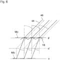
- the channel mask Mp in the principal plane p is not actually needed for constructing the channel mask Mo. Nevertheless, the channel mask Mo implicitly defines also a corresponding channel mask Mp, as has been shown in Fig. 6 .
- This channel mask Mp can be constructed "reversely” by moving the channel mask Mo into the auxiliary object plane o' and then drawing straight lines 46 from the boundaries of the channel zones in the object plane o' to the reference point U. The points where these lines 46 pass through the principal plane p define the boundaries of the channel zones of the channel mask Mp.
- the construction of the channel mask Mo by ray tracing is equivalent to defining the channel mask Mp in a suitable position relative to the lens array 18 (with channel zone boundaries offset from the apex lines of the cylindrical lenses) and then using the central projection to construct the channel mask Mo'.
- the cylindrical lenses 24 can be considered to be straight with sufficient accuracy, it is sufficient to calculate the refracted rays 44 only once for each cylindrical lens in order to construct the channel mask Mo.
- the apex lines 26 of the lenses are curved, as in Fig. 2 , it is preferred to trace a band of rays 44 passing through several points along the apex line 26, as has been shown in Fig. 7 .
- Fig. 8 shows a comparison between a corrected channel mask Mp constructed in accordance with the invention, i.e. by ray tracing, and a non-corrected channel mask as defined directly by the apex lines 26 of the cylindrical lenses. It can be seen that the offset between the corrected and uncorrected channel masks can amount to more than the width of an individual channel zone 38.
- the uncorrected channel mask, as defined directly by the apex lines 26 would be used for constructing a channel mask 48 in the object plane o by means of central projection onto the auxiliary object plane o', the viewer would perceive an inverted three dimensional image when looking at the screen under this large skew angle.
- the invention permits to avoid this effect even for displays with a large screen and/or for short viewing distances.
- Fig. 9 shows an example, where the parallax filter device is formed by a stripe array 50 constituted by a glass plate 52 with non-transparent stripes 54 printed on the top surface thereof.
- the stripes 54 will obscure the pixels in a left channel zone for the right eye of the user and the pixels in a right channel zone for the left eye of the user.
- the glass plate 52 is separated from the screen 16 by an air gap 56 (or possibly a transparent layer with a refractive index different from that of the glass plate).
- the rays 44 passing through the edges of the stripes 54 are traced on their way through the glass plate 52, where they are refracted twice, so as to find the boundaries of the channel zones of the channel mask Mo in the object plane o.
- an air gap similar to the air gap 56 may also be present between the cylindrical lens 18 and the screen 16 in the previous embodiment, and then a refraction of the rays 44 at the boundary of this air gap would also have to be taken into consideration in the ray tracing process.
- the invention can deal with arbitrary stacks of optical media consisting of an number of layers, each of them of individual thickness and with an individual refraction index, including the possibility of layers that are positioned on the viewer's side of principal plane p.
- Fig. 10 illustrates yet another embodiment where a parallax filter device is formed by a controllable gradient lens array 58.
- This lens array is formed by a transparent plane-parallel plate 60 made of a material the refractive index of which varies when an electric field is applied.
- Fine patterns of electrodes 62 and 64 are formed on the opposite surfaces of the plate 60, and when a voltage is applied between one of the electrodes 62 and an opposing one of the electrodes 64, the column of the material between these electrodes will change its refractive index. Consequently, by appropriately controlling the voltages applied to the pairs of electrodes 62, 64, it is possible to create a gradient in the refractive index of the plate 60. This gradient will cause a refraction of the rays 44, as has been shown in Fig. 10 .
- switchable or non-switchable lens arrays e.g. switchable or non-switchable anisotropic lens, switchable LCD-lens and others.
- the invention is even applicable to autostereoscopic displays which have a curved screen 16' and a curved lens array 18', as shown in Fig. 11 .
- the effect of the curvature may easily be taken into account when tracing the rays 44.
- a ray tracing software will be implemented in the computer system 10 ( Fig. 1 ) for calculating the rays through the various points of the lens array and the screen.
- the eye tracking system 20 detects a shift in the reference position U of the user, the calculations will be updated for the two new viewing positions of the left eye and the right eye.
- a viewing position may be defined as a position of a single eye, regardless of whether this eye is a left eye or a right eye of the user. Then, the necessary ray tracing calculations need to be made only once, and the views for which the image information is presented on the screen are selected in accordance with the information provided by the head tracking system 20.
- This embodiment may also be used in a multi-view system permitting two or more users to watch a three-dimensional scene simultaneously. A multi-view system of this type has been described in applicants co-pending European patent application EP 14 200 536.2 .
- two optical sensors may be arranged in the positions of the eyes 28, 30 of the viewer in Fig. 11 , and then the pixels on the screen 16' may be energized one after the other to see whether at least one of the two sensors detects a corresponding optical signal. Then, depending upon which of the two sensors has received a signal, the pixel that has been energized can be assigned to one of the channel zones.
- These measurements may be made for a single viewing position or for several viewing positions.
- ray tracing by measurement has the advantage that any manufacturing tolerances in the production of the lens array and/or the mounting of the lens array on the screen are eliminated automatically.
- a measurement for a single viewing position will normally not be sufficient to derive the exact shape and position of the lens array. However, by making measurements for two or more viewing positions, it will generally be possible to remove the ambiguity in the data, so that the exact shape and position of the lens array can be calculated from the measurement results. Then channel masks for other viewing positions which have not been measured, may be constructed by ray tracing calculations.
Landscapes
- Physics & Mathematics (AREA)
- Engineering & Computer Science (AREA)
- Multimedia (AREA)
- Signal Processing (AREA)
- General Physics & Mathematics (AREA)
- Optics & Photonics (AREA)
- Testing, Inspecting, Measuring Of Stereoscopic Televisions And Televisions (AREA)
- Optical Elements Other Than Lenses (AREA)
Claims (5)
- Verfahren zur Konstruktion einer Kanalmaske (Mo) für ein autostereoskopisches Display, das einen elektronisch angesteuerten Bildschirm (16) aufweist, der von einer Parallaxenfiltereinrichtung (18) überdeckt ist, die ein brechendes Medium aufweist und dazu konfiguriert ist, bestimmte Bereiche auf dem Bildschirm für ein linkes Auge (30) eines Betrachters zu verbergen und bestimmte andere Bereiche auf dem Bildschirm für ein rechtes Auge (28) des Betrachters zu verbergen, wobei die Kanalmaske (Mo) ein zweidimensionales geometrisches Objekt ist, das es erlaubt, jedem Punkt auf dem Bildschirm (16) eine Betrachtungsposition aus einer Anzahl von Betrachtungspositionen eines Auges des Betrachters zuzuweisen, wobei die Kanalmaske die Oberfläche des Bildschirms in getrennte Kanalzonen (36) unterteilt, die von einer gegebenen Position des Betrachters aus für nicht mehr als ein Auge des Betrachters sichtbar sind, wobei Grenzen (40, 42) zwischen den Kanalzonen durch entsprechende Merkmale der Parallaxenfiltereinrichtung bestimmt werden, dadurch gekennzeichnet, dass die Kanalmaske konstruiert wird, indem Lichtstrahlen (32, 34) verfolgt werden, die sich von ausgewählten Punkten auf dem Bildschirm ausbreiten und an der Parallaxenfiltereinrichtung gebrochen werden, wobei die Grenzen (40, 42) durch gebrochene Lichtstrahlen (44) definiert werden, die einen Referenzpunkt (U) für die Position des Betrachters mit den genannten Merkmalen der Parallaxenfiltereinrichtung verbinden.
- Verfahren nach Anspruch 1, bei dem die Parallaxenfiltereinrichtung (18) ein Linsenarray ist.
- Verfahren nach Anspruch 1, bei dem die Parallaxenfiltereinrichtung ein Streifenarray ist.
- Verfahren nach Anspruch 1, bei dem für die Strahlverfolgung ein Softwarealgorithmus benutzt wird.
- Verfahren nach Anspruch 1, bei dem mehrere Kanalmasken (Mo) für wenigstens zwei verschiedene Betrachtungspositionen berechnet werden.
Applications Claiming Priority (2)
| Application Number | Priority Date | Filing Date | Title |
|---|---|---|---|
| US14/723,952 US9952426B2 (en) | 2015-05-28 | 2015-05-28 | Autostereoscopic system |
| PCT/EP2016/060528 WO2016188748A1 (en) | 2015-05-28 | 2016-05-11 | Autostereoscopic system |
Publications (2)
| Publication Number | Publication Date |
|---|---|
| EP3304899A1 EP3304899A1 (de) | 2018-04-11 |
| EP3304899B1 true EP3304899B1 (de) | 2020-08-19 |
Family
ID=55953171
Family Applications (1)
| Application Number | Title | Priority Date | Filing Date |
|---|---|---|---|
| EP16721443.6A Not-in-force EP3304899B1 (de) | 2015-05-28 | 2016-05-11 | Autostereoskopisches system |
Country Status (6)
| Country | Link |
|---|---|
| US (1) | US9952426B2 (de) |
| EP (1) | EP3304899B1 (de) |
| JP (1) | JP6588107B2 (de) |
| KR (1) | KR101987721B1 (de) |
| CN (1) | CN108012556B (de) |
| WO (1) | WO2016188748A1 (de) |
Families Citing this family (6)
| Publication number | Priority date | Publication date | Assignee | Title |
|---|---|---|---|---|
| US10991280B2 (en) * | 2017-05-01 | 2021-04-27 | Pure Depth Limited | Head tracking based field sequential saccadic break up reduction |
| US11782190B2 (en) * | 2019-09-06 | 2023-10-10 | Apple Inc. | Optical film arrangements for electronic device displays |
| TWI806376B (zh) * | 2022-01-22 | 2023-06-21 | 宏碁股份有限公司 | 立體影像生成盒、立體影像顯示方法及立體影像顯示系統 |
| JP7613392B2 (ja) * | 2022-02-02 | 2025-01-15 | トヨタ自動車株式会社 | 情報処理装置、方法、及びプログラム |
| US12044865B2 (en) * | 2022-04-16 | 2024-07-23 | Kamil Podhola | Liquid crystal system display for stereovision |
| US12401777B2 (en) | 2023-04-12 | 2025-08-26 | Apple Inc. | Pixel arrangements for displays with lenticular lenses |
Family Cites Families (19)
| Publication number | Priority date | Publication date | Assignee | Title |
|---|---|---|---|---|
| US5448322A (en) * | 1993-11-05 | 1995-09-05 | Vision Iii Imaging, Inc. | Autostereoscopic imaging apparatus and method using a parallax scanning lens aperture |
| GB9411561D0 (en) * | 1994-06-07 | 1994-08-03 | Richmond Holographic Res | Stereoscopic display |
| GB2320156A (en) * | 1996-12-07 | 1998-06-10 | Sharp Kk | Directional display and method of making a mask for a directional display |
| US5771066A (en) * | 1997-01-03 | 1998-06-23 | Barnea; Daniel I. | Three dimensional display device |
| DE19827590C2 (de) | 1998-06-20 | 2001-05-03 | Christoph Grosmann | Verfahren und Vorrichtung zur Autostereoskopie |
| CN1476730A (zh) * | 2001-07-27 | 2004-02-18 | 皇家菲利浦电子有限公司 | 具有观看者跟踪系统的自动立体图像显示装置 |
| US7301587B2 (en) * | 2003-02-28 | 2007-11-27 | Nec Corporation | Image display device and portable terminal device using the same |
| US7697751B2 (en) * | 2005-12-29 | 2010-04-13 | Graphics Properties Holdings, Inc. | Use of ray tracing for generating images for auto-stereo displays |
| CN101460895A (zh) * | 2006-04-17 | 2009-06-17 | 三维Ip有限责任公司 | 用于角切片真三维显示的系统和方法 |
| JP4950293B2 (ja) * | 2006-07-24 | 2012-06-13 | シーフロント ゲゼルシャフト ミット ベシュレンクテル ハフツング | 自動立体システム |
| US20090046037A1 (en) * | 2007-08-17 | 2009-02-19 | The University Of British Columbia | High resolution display of 3d images |
| US8253780B2 (en) * | 2008-03-04 | 2012-08-28 | Genie Lens Technology, LLC | 3D display system using a lenticular lens array variably spaced apart from a display screen |
| US20110075256A1 (en) * | 2008-06-02 | 2011-03-31 | Koninklijke Philips Electronics N.V. | optical arrangement and an autostereoscopic display device incorporating the same |
| US8857028B2 (en) * | 2008-07-08 | 2014-10-14 | 3M Innovative Properties Company | Processes for producing optical elements showing virtual images |
| JP5238429B2 (ja) * | 2008-09-25 | 2013-07-17 | 株式会社東芝 | 立体映像撮影装置および立体映像撮影システム |
| JP2010181450A (ja) * | 2009-02-03 | 2010-08-19 | Olympus Corp | 視覚表示装置 |
| EP2490451A1 (de) * | 2011-02-18 | 2012-08-22 | Koninklijke Philips Electronics N.V. | Autostereoskopische Anzeigevorrichtung |
| EP2615838B1 (de) | 2012-01-12 | 2019-08-21 | SeeFront GmbH | Kalibrierung eines autostereoskopischen Anzeigesystems |
| US9341859B2 (en) * | 2012-07-06 | 2016-05-17 | Innolux Corporation | 3D image based alignment method |
-
2015
- 2015-05-28 US US14/723,952 patent/US9952426B2/en active Active
-
2016
- 2016-05-11 WO PCT/EP2016/060528 patent/WO2016188748A1/en not_active Ceased
- 2016-05-11 EP EP16721443.6A patent/EP3304899B1/de not_active Not-in-force
- 2016-05-11 KR KR1020177034438A patent/KR101987721B1/ko not_active Expired - Fee Related
- 2016-05-11 JP JP2017561868A patent/JP6588107B2/ja not_active Expired - Fee Related
- 2016-05-11 CN CN201680031007.7A patent/CN108012556B/zh not_active Expired - Fee Related
Non-Patent Citations (1)
| Title |
|---|
| None * |
Also Published As
| Publication number | Publication date |
|---|---|
| US20160349503A1 (en) | 2016-12-01 |
| JP6588107B2 (ja) | 2019-10-09 |
| CN108012556B (zh) | 2021-03-05 |
| EP3304899A1 (de) | 2018-04-11 |
| WO2016188748A1 (en) | 2016-12-01 |
| CN108012556A (zh) | 2018-05-08 |
| KR101987721B1 (ko) | 2019-06-11 |
| US9952426B2 (en) | 2018-04-24 |
| JP2018524627A (ja) | 2018-08-30 |
| KR20170140393A (ko) | 2017-12-20 |
Similar Documents
| Publication | Publication Date | Title |
|---|---|---|
| EP3304899B1 (de) | Autostereoskopisches system | |
| US9628784B2 (en) | Autostereoscopic display and method of displaying a 3D image | |
| CN105828060B (zh) | 立体显示装置及视差图像校正方法 | |
| US9420268B2 (en) | Apparatus and method for displaying 3-dimensional image | |
| US9467686B2 (en) | Stereoscopic display device for stereoscopic viewing at multiple viewing points | |
| JP2010529495A (ja) | モニタ上でパララックスバリアスクリーンを位置合わせする方法 | |
| KR20030030365A (ko) | 3차원 영상 표시장치 | |
| KR20120109303A (ko) | 표시 장치 | |
| CN111095080B (zh) | 在n视点立体显示屏上显示两视点立体图像的系统和方法 | |
| EP2839665B1 (de) | Autostereoskopischer anzeigeschirm und verfahren zur wiedergabe eines 3d-bildes | |
| CN105230012B (zh) | 用于再生图像信息的方法和自动立体屏幕 | |
| KR101852819B1 (ko) | 입체영상 디스플레이 장치 및 방법 | |
| US20180157055A1 (en) | Three-dimensional display device | |
| CN107065378A (zh) | 一种液晶光栅、显示装置及其显示方法 | |
| KR100416549B1 (ko) | 다안식 3차원 영상 표시장치 | |
| WO2013110297A1 (en) | Autostereoscopic display and method of displaying a 3d image | |
| KR20130038494A (ko) | 표시장치 및 그 제조방법 | |
| KR20130064278A (ko) | 영상표시장치 및 그 제조방법 |
Legal Events
| Date | Code | Title | Description |
|---|---|---|---|
| STAA | Information on the status of an ep patent application or granted ep patent |
Free format text: STATUS: THE INTERNATIONAL PUBLICATION HAS BEEN MADE |
|
| PUAI | Public reference made under article 153(3) epc to a published international application that has entered the european phase |
Free format text: ORIGINAL CODE: 0009012 |
|
| STAA | Information on the status of an ep patent application or granted ep patent |
Free format text: STATUS: REQUEST FOR EXAMINATION WAS MADE |
|
| 17P | Request for examination filed |
Effective date: 20171103 |
|
| AK | Designated contracting states |
Kind code of ref document: A1 Designated state(s): AL AT BE BG CH CY CZ DE DK EE ES FI FR GB GR HR HU IE IS IT LI LT LU LV MC MK MT NL NO PL PT RO RS SE SI SK SM TR |
|
| AX | Request for extension of the european patent |
Extension state: BA ME |
|
| DAV | Request for validation of the european patent (deleted) | ||
| DAX | Request for extension of the european patent (deleted) | ||
| RAP1 | Party data changed (applicant data changed or rights of an application transferred) |
Owner name: SEEFRONT GMBH |
|
| REG | Reference to a national code |
Ref country code: DE Ref legal event code: R079 Ref document number: 602016042240 Country of ref document: DE Free format text: PREVIOUS MAIN CLASS: H04N0013040000 Ipc: H04N0013300000 |
|
| GRAP | Despatch of communication of intention to grant a patent |
Free format text: ORIGINAL CODE: EPIDOSNIGR1 |
|
| STAA | Information on the status of an ep patent application or granted ep patent |
Free format text: STATUS: GRANT OF PATENT IS INTENDED |
|
| RIC1 | Information provided on ipc code assigned before grant |
Ipc: H04N 13/359 20180101ALI20200330BHEP Ipc: H04N 13/38 20180101ALI20200330BHEP Ipc: G02B 27/00 20060101ALI20200330BHEP Ipc: H04N 13/31 20180101ALI20200330BHEP Ipc: H04N 13/398 20180101ALI20200330BHEP Ipc: H04N 13/302 20180101ALI20200330BHEP Ipc: G02B 30/27 20200101ALI20200330BHEP Ipc: H04N 13/366 20180101ALI20200330BHEP Ipc: H04N 13/383 20180101ALI20200330BHEP Ipc: H04N 13/30 20180101AFI20200330BHEP |
|
| INTG | Intention to grant announced |
Effective date: 20200416 |
|
| GRAS | Grant fee paid |
Free format text: ORIGINAL CODE: EPIDOSNIGR3 |
|
| GRAA | (expected) grant |
Free format text: ORIGINAL CODE: 0009210 |
|
| STAA | Information on the status of an ep patent application or granted ep patent |
Free format text: STATUS: THE PATENT HAS BEEN GRANTED |
|
| AK | Designated contracting states |
Kind code of ref document: B1 Designated state(s): AL AT BE BG CH CY CZ DE DK EE ES FI FR GB GR HR HU IE IS IT LI LT LU LV MC MK MT NL NO PL PT RO RS SE SI SK SM TR |
|
| REG | Reference to a national code |
Ref country code: CH Ref legal event code: EP |
|
| REG | Reference to a national code |
Ref country code: DE Ref legal event code: R096 Ref document number: 602016042240 Country of ref document: DE |
|
| REG | Reference to a national code |
Ref country code: AT Ref legal event code: REF Ref document number: 1305287 Country of ref document: AT Kind code of ref document: T Effective date: 20200915 |
|
| REG | Reference to a national code |
Ref country code: IE Ref legal event code: FG4D |
|
| REG | Reference to a national code |
Ref country code: NL Ref legal event code: FP |
|
| REG | Reference to a national code |
Ref country code: LT Ref legal event code: MG4D |
|
| PG25 | Lapsed in a contracting state [announced via postgrant information from national office to epo] |
Ref country code: SE Free format text: LAPSE BECAUSE OF FAILURE TO SUBMIT A TRANSLATION OF THE DESCRIPTION OR TO PAY THE FEE WITHIN THE PRESCRIBED TIME-LIMIT Effective date: 20200819 Ref country code: BG Free format text: LAPSE BECAUSE OF FAILURE TO SUBMIT A TRANSLATION OF THE DESCRIPTION OR TO PAY THE FEE WITHIN THE PRESCRIBED TIME-LIMIT Effective date: 20201119 Ref country code: NO Free format text: LAPSE BECAUSE OF FAILURE TO SUBMIT A TRANSLATION OF THE DESCRIPTION OR TO PAY THE FEE WITHIN THE PRESCRIBED TIME-LIMIT Effective date: 20201119 Ref country code: PT Free format text: LAPSE BECAUSE OF FAILURE TO SUBMIT A TRANSLATION OF THE DESCRIPTION OR TO PAY THE FEE WITHIN THE PRESCRIBED TIME-LIMIT Effective date: 20201221 Ref country code: FI Free format text: LAPSE BECAUSE OF FAILURE TO SUBMIT A TRANSLATION OF THE DESCRIPTION OR TO PAY THE FEE WITHIN THE PRESCRIBED TIME-LIMIT Effective date: 20200819 Ref country code: LT Free format text: LAPSE BECAUSE OF FAILURE TO SUBMIT A TRANSLATION OF THE DESCRIPTION OR TO PAY THE FEE WITHIN THE PRESCRIBED TIME-LIMIT Effective date: 20200819 Ref country code: HR Free format text: LAPSE BECAUSE OF FAILURE TO SUBMIT A TRANSLATION OF THE DESCRIPTION OR TO PAY THE FEE WITHIN THE PRESCRIBED TIME-LIMIT Effective date: 20200819 Ref country code: GR Free format text: LAPSE BECAUSE OF FAILURE TO SUBMIT A TRANSLATION OF THE DESCRIPTION OR TO PAY THE FEE WITHIN THE PRESCRIBED TIME-LIMIT Effective date: 20201120 |
|
| REG | Reference to a national code |
Ref country code: AT Ref legal event code: MK05 Ref document number: 1305287 Country of ref document: AT Kind code of ref document: T Effective date: 20200819 |
|
| PG25 | Lapsed in a contracting state [announced via postgrant information from national office to epo] |
Ref country code: LV Free format text: LAPSE BECAUSE OF FAILURE TO SUBMIT A TRANSLATION OF THE DESCRIPTION OR TO PAY THE FEE WITHIN THE PRESCRIBED TIME-LIMIT Effective date: 20200819 Ref country code: PL Free format text: LAPSE BECAUSE OF FAILURE TO SUBMIT A TRANSLATION OF THE DESCRIPTION OR TO PAY THE FEE WITHIN THE PRESCRIBED TIME-LIMIT Effective date: 20200819 Ref country code: RS Free format text: LAPSE BECAUSE OF FAILURE TO SUBMIT A TRANSLATION OF THE DESCRIPTION OR TO PAY THE FEE WITHIN THE PRESCRIBED TIME-LIMIT Effective date: 20200819 Ref country code: IS Free format text: LAPSE BECAUSE OF FAILURE TO SUBMIT A TRANSLATION OF THE DESCRIPTION OR TO PAY THE FEE WITHIN THE PRESCRIBED TIME-LIMIT Effective date: 20201219 |
|
| PG25 | Lapsed in a contracting state [announced via postgrant information from national office to epo] |
Ref country code: CZ Free format text: LAPSE BECAUSE OF FAILURE TO SUBMIT A TRANSLATION OF THE DESCRIPTION OR TO PAY THE FEE WITHIN THE PRESCRIBED TIME-LIMIT Effective date: 20200819 Ref country code: DK Free format text: LAPSE BECAUSE OF FAILURE TO SUBMIT A TRANSLATION OF THE DESCRIPTION OR TO PAY THE FEE WITHIN THE PRESCRIBED TIME-LIMIT Effective date: 20200819 Ref country code: RO Free format text: LAPSE BECAUSE OF FAILURE TO SUBMIT A TRANSLATION OF THE DESCRIPTION OR TO PAY THE FEE WITHIN THE PRESCRIBED TIME-LIMIT Effective date: 20200819 Ref country code: SM Free format text: LAPSE BECAUSE OF FAILURE TO SUBMIT A TRANSLATION OF THE DESCRIPTION OR TO PAY THE FEE WITHIN THE PRESCRIBED TIME-LIMIT Effective date: 20200819 Ref country code: EE Free format text: LAPSE BECAUSE OF FAILURE TO SUBMIT A TRANSLATION OF THE DESCRIPTION OR TO PAY THE FEE WITHIN THE PRESCRIBED TIME-LIMIT Effective date: 20200819 |
|
| REG | Reference to a national code |
Ref country code: DE Ref legal event code: R097 Ref document number: 602016042240 Country of ref document: DE |
|
| PG25 | Lapsed in a contracting state [announced via postgrant information from national office to epo] |
Ref country code: AT Free format text: LAPSE BECAUSE OF FAILURE TO SUBMIT A TRANSLATION OF THE DESCRIPTION OR TO PAY THE FEE WITHIN THE PRESCRIBED TIME-LIMIT Effective date: 20200819 Ref country code: AL Free format text: LAPSE BECAUSE OF FAILURE TO SUBMIT A TRANSLATION OF THE DESCRIPTION OR TO PAY THE FEE WITHIN THE PRESCRIBED TIME-LIMIT Effective date: 20200819 Ref country code: ES Free format text: LAPSE BECAUSE OF FAILURE TO SUBMIT A TRANSLATION OF THE DESCRIPTION OR TO PAY THE FEE WITHIN THE PRESCRIBED TIME-LIMIT Effective date: 20200819 |
|
| PLBE | No opposition filed within time limit |
Free format text: ORIGINAL CODE: 0009261 |
|
| STAA | Information on the status of an ep patent application or granted ep patent |
Free format text: STATUS: NO OPPOSITION FILED WITHIN TIME LIMIT |
|
| PG25 | Lapsed in a contracting state [announced via postgrant information from national office to epo] |
Ref country code: SK Free format text: LAPSE BECAUSE OF FAILURE TO SUBMIT A TRANSLATION OF THE DESCRIPTION OR TO PAY THE FEE WITHIN THE PRESCRIBED TIME-LIMIT Effective date: 20200819 |
|
| 26N | No opposition filed |
Effective date: 20210520 |
|
| PG25 | Lapsed in a contracting state [announced via postgrant information from national office to epo] |
Ref country code: IT Free format text: LAPSE BECAUSE OF FAILURE TO SUBMIT A TRANSLATION OF THE DESCRIPTION OR TO PAY THE FEE WITHIN THE PRESCRIBED TIME-LIMIT Effective date: 20200819 |
|
| PG25 | Lapsed in a contracting state [announced via postgrant information from national office to epo] |
Ref country code: SI Free format text: LAPSE BECAUSE OF FAILURE TO SUBMIT A TRANSLATION OF THE DESCRIPTION OR TO PAY THE FEE WITHIN THE PRESCRIBED TIME-LIMIT Effective date: 20200819 |
|
| REG | Reference to a national code |
Ref country code: CH Ref legal event code: PL |
|
| PG25 | Lapsed in a contracting state [announced via postgrant information from national office to epo] |
Ref country code: LU Free format text: LAPSE BECAUSE OF NON-PAYMENT OF DUE FEES Effective date: 20210511 Ref country code: MC Free format text: LAPSE BECAUSE OF FAILURE TO SUBMIT A TRANSLATION OF THE DESCRIPTION OR TO PAY THE FEE WITHIN THE PRESCRIBED TIME-LIMIT Effective date: 20200819 Ref country code: LI Free format text: LAPSE BECAUSE OF NON-PAYMENT OF DUE FEES Effective date: 20210531 Ref country code: CH Free format text: LAPSE BECAUSE OF NON-PAYMENT OF DUE FEES Effective date: 20210531 |
|
| REG | Reference to a national code |
Ref country code: BE Ref legal event code: MM Effective date: 20210531 |
|
| PG25 | Lapsed in a contracting state [announced via postgrant information from national office to epo] |
Ref country code: IE Free format text: LAPSE BECAUSE OF NON-PAYMENT OF DUE FEES Effective date: 20210511 |
|
| PG25 | Lapsed in a contracting state [announced via postgrant information from national office to epo] |
Ref country code: BE Free format text: LAPSE BECAUSE OF NON-PAYMENT OF DUE FEES Effective date: 20210531 |
|
| PG25 | Lapsed in a contracting state [announced via postgrant information from national office to epo] |
Ref country code: CY Free format text: LAPSE BECAUSE OF FAILURE TO SUBMIT A TRANSLATION OF THE DESCRIPTION OR TO PAY THE FEE WITHIN THE PRESCRIBED TIME-LIMIT Effective date: 20200819 |
|
| PG25 | Lapsed in a contracting state [announced via postgrant information from national office to epo] |
Ref country code: HU Free format text: LAPSE BECAUSE OF FAILURE TO SUBMIT A TRANSLATION OF THE DESCRIPTION OR TO PAY THE FEE WITHIN THE PRESCRIBED TIME-LIMIT; INVALID AB INITIO Effective date: 20160511 |
|
| PGFP | Annual fee paid to national office [announced via postgrant information from national office to epo] |
Ref country code: NL Payment date: 20230519 Year of fee payment: 8 Ref country code: FR Payment date: 20230517 Year of fee payment: 8 Ref country code: DE Payment date: 20230525 Year of fee payment: 8 |
|
| PGFP | Annual fee paid to national office [announced via postgrant information from national office to epo] |
Ref country code: GB Payment date: 20230522 Year of fee payment: 8 |
|
| PG25 | Lapsed in a contracting state [announced via postgrant information from national office to epo] |
Ref country code: MK Free format text: LAPSE BECAUSE OF FAILURE TO SUBMIT A TRANSLATION OF THE DESCRIPTION OR TO PAY THE FEE WITHIN THE PRESCRIBED TIME-LIMIT Effective date: 20200819 |
|
| PG25 | Lapsed in a contracting state [announced via postgrant information from national office to epo] |
Ref country code: MT Free format text: LAPSE BECAUSE OF FAILURE TO SUBMIT A TRANSLATION OF THE DESCRIPTION OR TO PAY THE FEE WITHIN THE PRESCRIBED TIME-LIMIT Effective date: 20200819 |
|
| REG | Reference to a national code |
Ref country code: DE Ref legal event code: R119 Ref document number: 602016042240 Country of ref document: DE |
|
| REG | Reference to a national code |
Ref country code: NL Ref legal event code: MM Effective date: 20240601 |
|
| GBPC | Gb: european patent ceased through non-payment of renewal fee |
Effective date: 20240511 |
|
| PG25 | Lapsed in a contracting state [announced via postgrant information from national office to epo] |
Ref country code: NL Free format text: LAPSE BECAUSE OF NON-PAYMENT OF DUE FEES Effective date: 20240601 |
|
| PG25 | Lapsed in a contracting state [announced via postgrant information from national office to epo] |
Ref country code: DE Free format text: LAPSE BECAUSE OF NON-PAYMENT OF DUE FEES Effective date: 20241203 |
|
| PG25 | Lapsed in a contracting state [announced via postgrant information from national office to epo] |
Ref country code: FR Free format text: LAPSE BECAUSE OF NON-PAYMENT OF DUE FEES Effective date: 20240531 |
|
| PG25 | Lapsed in a contracting state [announced via postgrant information from national office to epo] |
Ref country code: GB Free format text: LAPSE BECAUSE OF NON-PAYMENT OF DUE FEES Effective date: 20240511 |
|
| PG25 | Lapsed in a contracting state [announced via postgrant information from national office to epo] |
Ref country code: TR Free format text: LAPSE BECAUSE OF FAILURE TO SUBMIT A TRANSLATION OF THE DESCRIPTION OR TO PAY THE FEE WITHIN THE PRESCRIBED TIME-LIMIT Effective date: 20200819 |