EP3305178A2 - Verfahren zur bestimmung eines geometrischen parameters eines auges einer person - Google Patents
Verfahren zur bestimmung eines geometrischen parameters eines auges einer person Download PDFInfo
- Publication number
- EP3305178A2 EP3305178A2 EP17194551.2A EP17194551A EP3305178A2 EP 3305178 A2 EP3305178 A2 EP 3305178A2 EP 17194551 A EP17194551 A EP 17194551A EP 3305178 A2 EP3305178 A2 EP 3305178A2
- Authority
- EP
- European Patent Office
- Prior art keywords
- eye
- image
- pupil
- images
- determined
- Prior art date
- Legal status (The legal status is an assumption and is not a legal conclusion. Google has not performed a legal analysis and makes no representation as to the accuracy of the status listed.)
- Granted
Links
Images
Classifications
-
- G—PHYSICS
- G02—OPTICS
- G02C—SPECTACLES; SUNGLASSES OR GOGGLES INSOFAR AS THEY HAVE THE SAME FEATURES AS SPECTACLES; CONTACT LENSES
- G02C7/00—Optical parts
- G02C7/02—Lenses; Lens systems ; Methods of designing lenses
- G02C7/024—Methods of designing ophthalmic lenses
- G02C7/027—Methods of designing ophthalmic lenses considering wearer's parameters
-
- A—HUMAN NECESSITIES
- A61—MEDICAL OR VETERINARY SCIENCE; HYGIENE
- A61B—DIAGNOSIS; SURGERY; IDENTIFICATION
- A61B3/00—Apparatus for testing the eyes; Instruments for examining the eyes
- A61B3/10—Objective types, i.e. instruments for examining the eyes independent of the patients' perceptions or reactions
- A61B3/113—Objective types, i.e. instruments for examining the eyes independent of the patients' perceptions or reactions for determining or recording eye movement
-
- A—HUMAN NECESSITIES
- A61—MEDICAL OR VETERINARY SCIENCE; HYGIENE
- A61B—DIAGNOSIS; SURGERY; IDENTIFICATION
- A61B3/00—Apparatus for testing the eyes; Instruments for examining the eyes
- A61B3/0016—Operational features thereof
- A61B3/0025—Operational features thereof characterised by electronic signal processing, e.g. eye models
-
- A—HUMAN NECESSITIES
- A61—MEDICAL OR VETERINARY SCIENCE; HYGIENE
- A61B—DIAGNOSIS; SURGERY; IDENTIFICATION
- A61B3/00—Apparatus for testing the eyes; Instruments for examining the eyes
- A61B3/10—Objective types, i.e. instruments for examining the eyes independent of the patients' perceptions or reactions
- A61B3/107—Objective types, i.e. instruments for examining the eyes independent of the patients' perceptions or reactions for determining the shape or measuring the curvature of the cornea
-
- A—HUMAN NECESSITIES
- A61—MEDICAL OR VETERINARY SCIENCE; HYGIENE
- A61B—DIAGNOSIS; SURGERY; IDENTIFICATION
- A61B3/00—Apparatus for testing the eyes; Instruments for examining the eyes
- A61B3/10—Objective types, i.e. instruments for examining the eyes independent of the patients' perceptions or reactions
- A61B3/14—Arrangements specially adapted for eye photography
-
- A—HUMAN NECESSITIES
- A61—MEDICAL OR VETERINARY SCIENCE; HYGIENE
- A61B—DIAGNOSIS; SURGERY; IDENTIFICATION
- A61B3/00—Apparatus for testing the eyes; Instruments for examining the eyes
- A61B3/10—Objective types, i.e. instruments for examining the eyes independent of the patients' perceptions or reactions
- A61B3/11—Objective types, i.e. instruments for examining the eyes independent of the patients' perceptions or reactions for measuring interpupillary distance or diameter of pupils
- A61B3/112—Objective types, i.e. instruments for examining the eyes independent of the patients' perceptions or reactions for measuring interpupillary distance or diameter of pupils for measuring diameter of pupils
-
- G—PHYSICS
- G06—COMPUTING OR CALCULATING; COUNTING
- G06T—IMAGE DATA PROCESSING OR GENERATION, IN GENERAL
- G06T2207/00—Indexing scheme for image analysis or image enhancement
- G06T2207/30—Subject of image; Context of image processing
- G06T2207/30004—Biomedical image processing
- G06T2207/30041—Eye; Retina; Ophthalmic
-
- G—PHYSICS
- G06—COMPUTING OR CALCULATING; COUNTING
- G06T—IMAGE DATA PROCESSING OR GENERATION, IN GENERAL
- G06T7/00—Image analysis
- G06T7/70—Determining position or orientation of objects or cameras
- G06T7/73—Determining position or orientation of objects or cameras using feature-based methods
- G06T7/74—Determining position or orientation of objects or cameras using feature-based methods involving reference images or patches
-
- G—PHYSICS
- G16—INFORMATION AND COMMUNICATION TECHNOLOGY [ICT] SPECIALLY ADAPTED FOR SPECIFIC APPLICATION FIELDS
- G16H—HEALTHCARE INFORMATICS, i.e. INFORMATION AND COMMUNICATION TECHNOLOGY [ICT] SPECIALLY ADAPTED FOR THE HANDLING OR PROCESSING OF MEDICAL OR HEALTHCARE DATA
- G16H50/00—ICT specially adapted for medical diagnosis, medical simulation or medical data mining; ICT specially adapted for detecting, monitoring or modelling epidemics or pandemics
- G16H50/50—ICT specially adapted for medical diagnosis, medical simulation or medical data mining; ICT specially adapted for detecting, monitoring or modelling epidemics or pandemics for simulation or modelling of medical disorders
Definitions
- the invention relates to a method for determining a geometrical parameter of an eye of a subject.
- the present invention relates in general to taking geometrico-morphological measurements of a subject.
- the invention relates to a method of determining a geometrical parameter of an eye of a subject.
- a particular, but non-exclusive, application of the invention lies in taking geometrico-morphological measurements on a future subject of eyeglasses for the purpose of personalizing the optical design of the corrective ophthalmic lenses that are to be mounted in the frame selected by said future subject.
- the position of a center of rotation of at least one of the eye is determined.
- Movement of the eye can generally be considered as being a combination of rotations about a particular point that is referred to as the center of rotation of the eye (ERC).
- the position of the ERC may be deduced approximately from the position of the cornea by assuming a mean value for the radius of the eye, typically a value of about 15 millimeters (mm).
- a mean value for the radius of the eye typically a value of about 15 millimeters (mm).
- the radius of the eye varies significantly from one individual to another, such that this approximation leads to significant errors that are highly penalizing for the pertinence of the personalized optical design calculation.
- the reference accessory gives information on the relative position of the head of the subject and the image capture device.
- one object of the invention is to provide a method to determine quickly the position of the center of rotation of the eye, in a natural posture, without using a reference accessory.
- This object is achieved according to the invention by providing a method for determining a geometrical parameter of an eye of a subject, comprising the following steps:
- the geometrical parameter of the eye is determined quickly and in a simple manner, based on two images of the eye, without the use of a reference accessory.
- the method according to the invention indeed only requires one image capture device to be implemented.
- the method according to the invention allows determining the position the center of rotation of the eye of the subject, relative to the image capture device.
- It also allows determining the position of the center of rotation of the eye relative to an eyewear frame or relative to an instrument. This may be useful in order to take measurements for adjusting the optical equipment to the shape of the face of the subject.
- the determination of the values of many of theses parameters require the determination of a geometrical parameter of the eye of the subject, for example of the position of the center of rotation of the eye of the subject, in a referential.
- This geometrical parameter of the eye of the subject may be determined according to the invention, through the following steps:
- the geometrical parameter of the eye is determined quickly and in a simple manner, based on two images of the eye, without the use of a reference accessory.
- the method according to the invention indeed only requires one image capture device to be implemented.
- more than two images are captured and treated as described below, for example at least three images, at least five, at least 10 images or more than 10 images.
- step a) comprises the following sub-steps:
- the gaze direction is the direction in which the subject is looking. It may be defined as the axis going through the center of rotation of the eye and the center of the pupil of the eye. The gaze direction also goes through the sighting point fixed by the subject.
- the two different gaze directions are spaced apart by at least 30 degrees of angle.
- this is achieved preferably by capturing a plurality of images of the eye while the subject moves his eyes, while the image capture device remains at a fixed position compared to the eye.
- Said image capture device is placed on the head of the subject.
- the image capture device is preferably attached to the head of the subject.
- This support may be an eyeglasses frame placed on the head of the subject.
- Said image capture device is for example placed laterally on one side of the eye. It may therefore be attached to the branch and/or the corresponding circle of the frame.
- said image capture device is placed less than 2 centimeters away from the eye, preferably less than 1 centimeter away from the eye.
- the relative position of the image capture device and the head of the subject is fixed during the capture of said plurality of images.
- the image capture device is for example a camera, preferably a movie camera.
- the plurality of images captured is transmitted to a computer unit.
- the image capture device may be integrated with this computer unit or form an independent element.
- the capture of a plurality of images of the eye may be performed during a specific calibration step, during which the subject is asked to gaze at the moving sighting point, or it may be performed continuously while tracking the eye of the subject with an eye-tracking device.
- the eye-tracking device may be calibrated in real time in order to correct any movement of the eye-tracking device relative to the eye.
- a plurality of images of the eye comprising more than two images, preferably more than five images, preferably more than ten images is captured while the subject looks at directions that are distinct for each image captured.
- step a a plurality of images of a side view of the eye is captured.
- each of said first and second images the image of a pupil and/or an iris of the eye is identified.
- This identification may be performed by any known conventional image treatment method, such as edge detection algorithms.
- the computer unit is programmed to identify the image of the pupil and/or the iris of the eye of the subject in each of the plurality of images captured.
- the computer unit is programmed to determine a geometrical feature of the image of the pupil and/or the iris linked to the shape of this image of the pupil and/or the iris.
- the optical axis of the image capture device and the gaze direction are not superposed, meaning that the pupil of the image capture device is offset compared to the gaze direction.
- a simple model of the eye comprises a circular pupil or iris, moving in rotation about the center of rotation of the eye, at a constant distance of this center of rotation, that is to say on a sphere of radius equal to R pupil .
- the image of the pupil and/or the iris of the subject on the image captured usually presents an elliptic shape.
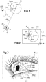
- the eye 20 of the subject is represented in space on figure 1 . It is represented here by the location where the pupil 10 of the subject moves when the subject moves his eye.
- the actual radius of the eye R eye is in fact slightly bigger than the radius R pupil of the location where the pupil moves.
- the gaze direction GD of the subject goes through the center CP of the pupil 10 of the subject and the center of rotation ERC of the eye 20.
- a referential (O, x, y, z) of the image capture device 30 is placed relative to the eye 20.
- the axis (O, z) links the pupil of the image capture device and the center of rotation of the eye. This axis will also be called below the observation axis OD.
- a tilt angle ⁇ lies between the observation axis and the gaze direction.
- the distance between the center CP of the pupil 10 and the center of rotation ERC of the eye 20 is the radius R pupil of the location where the pupil moves.
- Figure 2 shows the corresponding image I captured by the image capture device with the gaze direction GD forming the angle ⁇ with the observation axis OD.
- the image I10 of the pupil of the subject is shown in the image I20 of the eye of the subject.
- the image is then captured in the plane (O, x, y) of said referential linked to the image capture device 30.
- the image I10 of the pupil of the eye of the subject on the image I captured has the shape of an ellipse of center ICP.
- the outline of the image of the pupil 110 is therefore close to an ellipse.
- Said geometrical feature of the image of the pupil is linked to the shape of the outline of the image I10 of the pupil.
- This outline is determined by the computer unit, for example by an edge detection method.
- the computer unit is then programmed for determining said geometrical feature of the image of the pupil I10.
- the geometrical feature of the image of the pupil determined comprises the direction of at least one of the minor and major axis of the corresponding model ellipse, and/or a geometrical feature linked to the eccentricity of the model ellipse.
- the computer unit is programmed to determine the minor and/or major axis of the ellipse corresponding to the outline of the pupil.
- the computer unit is programmed to determine the model ellipse closest to the outline of the pupil, and determine its minor and major axis.
- the major axis of the ellipse is the longest diameter R gd of this ellipse, whereas the minor axis is the shortest diameter R pt of the ellipse.
- the model ellipse is determined by the following features: coordinates (xc, yc) of its center, its eccentricity e and/or the distance from the center of the ellipse to the perimeter along the minor and major axis of the ellipse and the angle of tilt ⁇ defined before.
- the determination of the model ellipse is achieved by determining the five features of this model ellipse for which the corresponding ellipse goes through the higher number of points of the actual outline of the pupil determined.
- a step of verification of the quality of the outline of the pupil determine may be implemented.
- a quality factor may be determined based on:
- the quality factor will be higher for a higher difference of contrast between the two sides of the outline.
- the size of the image of the pupil may be compared to a theoretical size determined based on parameters of the image capture device: distance between the image capture device and the eye, focal distance of the image capture device. The quality factor is then higher when the size of the image of the pupil determined is closer to the theoretical size calculated.
- the features of the outline determined by image treatment may also be compared to the outline determined for a previous image captured just before the current image treated, in order to determine if the features of the outline determined on the current image is consistent with the outline determined for the previous image. Based on the outline determined on the previous image and the movement of the eye (speed, trajectory), the variation of the outline between the two corresponding image capture may indeed be determined and an expected theoretical outline may be deduced. The quality factor will be higher with a higher consistence between the outline determined and the expected outline.
- Said geometrical feature of the image of the pupil is linked to the shape of the outline of the image I10 of the pupil.
- the geometrical feature of the image of the pupil determined comprises the direction of at least one of the minor and major axis of the corresponding model ellipse, and/or a geometrical feature linked to the eccentricity of the model ellipse.
- the computer unit is therefore programmed to determine at least one of the minor and major axis of the corresponding model ellipse, and/or said geometrical feature linked to the eccentricity of the model ellipse.
- the geometrical parameter of the eye determined comprises a position of the center of rotation of the eye relative to said image capture device.
- the geometrical parameter of the eye determined may comprise a distance relative to a dimension of the eye and/or a distance between a center of rotation of the eye and an image capture device and/or a angle between an optical axis of an image capture device and a gaze axis and/or a direction of the gaze axis and/or a position of a point of intersection between a lens of eyeglasses placed on front of the eye and the gaze axis.
- the computer unit is then programmed to determine the position of the center of rotation of the eye, for example according to the procedure described in the following. In this procedure, it is considered that:
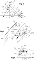
- step c) the images of the eye are superposed and the position of at least one intersection point between the minor axis of two of the model ellipses associated to the outlines of the images of the pupils is determined.
- the position of the center of rotation of the eye is deduced from the position of said intersection point determined.
- the position of the image of the center of rotation IERC of the eye may be identified with the intersection point of the minor axis M1, M2, M3, M4 of the model ellipses associated with at least two imagesI10 of the pupil.
- the position of the image of the center of rotation IERC of the eye is for example identified to the position of a mean intersection point of all the minor axis M1, M2, M3, M4 of the model ellipses associated to the images of the pupil determined.
- the position of the image of the center of rotation may be determined as a barycenter of the intersection points of the minor axis M1, M2, M3, M4. This identification may be performed graphically (see figure 3 ), or by calculation.
- the direction of the line going through the pupil of the image capture device and the center of rotation of the eye may be determined relative to the frame.
- the coordinates of the center of rotation in two dimensions in the image capture device referential are deduced.
- the coordinates of the center of rotation in three dimensions may be deduced based on known optical features of the image capture device.
- the coordinates of the center of rotation of the eye in the referential of the image capture device may be transposed in a real space referential.
- the determination of the position of the center of rotation of the eye is used in many situations.
- the precision obtained is less than 2° of angle, for example 1° of angle in the central field.
- the central field is for example defined as an angular zone centered on a primary gaze axis spreading over 30°, which corresponds to a central zone of the lens centered on the intersection of the primary gaze axis and the lens having a 15 millimeters diameter.
- It may be used for calibrating an eye-tracking device integrated in the eyeglasses frame worn by the subject.
- the position of the center of rotation may be checked to determine a movement of the eyeglasses frame relative to the head of the subject.
- Other geometrical parameters of the eye of the subject may be determined, for example, the radius of the eye.
- the eye is approximately the location where the pupil of the subject moves when the subject moves his eye.
- the radius of the eye may be approximated to the radius of the location of the pupil when the subject moves his eye.
- the actual pupil being circular with a radius equal to R gd
- R pupil is the radius of the location of the pupil when the subject moves his eye and Dist the distance between the image of the center of the pupil and the image of the center of rotation of the eye, in pixels ( figure 2 ).
- the distance Dist is measured on the image ( figure 2 ).
- R pupil is then calculated in pixels.
- the radius of the eye R eye may be estimated based on the radius R pupil of the location of the pupil.
- the position of the center of rotation is determined as described before.
- the primary gaze direction is the gaze direction when the subject looks straight ahead.
- the image capture device 30 is here supposed to be placed approximately in the mean plane of the lens.
- the mean plane of the lens may be replaced by a plane of know position relative to the image capture device.
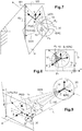
- An angle ⁇ between the observation axis OD and the tangent to the eye 20 at the intersection between the gaze direction GD and the eye is measured in degrees on the captured image, thanks to a calibration of the image ( figure 4 ).
- R eye d * sin ⁇ .
- this radius of the eye may for example be measured in pixels on the images captured.
- the parameter for changing referential may be determined as follows.
- Geometrical parameters of the eye such as position of the center of rotation, shapes of the image of the pupil when the eye moves, location of the pupils when the eye moves, observation axis, are determined, for example thanks to the method according to the invention.
- the mark of the point I 0 is noted on the lens.
- At least two images of the eye are captured while the eye looks at a reference horizontal line RH of space.
- the images then corresponds to the two different gaze direction GD1, GD2 of figure 5 , for the position P1 and P2 of the center of the pupil 10
- This reference horizontal line may for example be the intersection between a wall W1 and the ceiling CL in a room.
- the angle ⁇ horizontal between the two gaze direction GD1 and GD2 is maximum, for example superior to 30°.
- the axis going through the centers P1, P2 of the pupil 10 in these two images capture is taken as the (I 0 , X) axis of the referential (I 0 , X, Y, Z) of space linked to the gaze direction in real space.
- Figure 6 show the superposition I1 of the two images captured in the situation described in reference to figure 5 .
- an angle ⁇ 0 exists between the (I 0 , X) axis of the referential linked to the gaze direction in real space and the (O, x) axis linked to the image capture device.
- the change of referential may be determined for the vertical axis.
- At least two images of the eye are captured while the eye looks at a reference vertical line RV of space.
- the images then corresponds to the two different gaze direction GD3, GD4 of figure 7 , for the position P3 and P4 of the center of the pupil 10.
- This reference vertical line may for example be the intersection between the wall W1 and another wall W2 in a room.
- the angle ⁇ vertical between the two gaze directions GD3 and GD4 is maximal, for example superior to 30°.
- the axis going through the centers P3, P4 of the pupil 10 in these two images captured is taken as the (I 0 , Y) axis of the referential (I 0 , X, Y, Z) of space linked to the gaze direction in real space.
- Figure 8 show the superposition I 2 of the two images captured in the situation described in reference to figure 7 .
- an angle ⁇ 0 exists between the (I 0 , Y) axis of the referential linked to the gaze direction in real space and the (O, y) axis linked to the image capture device.
- the referential (I 0 , X, Y) is projected on the lens P.
- the change of referential may be performed between the image capture device and the boxing referential.
- the X axis is then marked by a checkerboard test pattern imaged by the image capture device.
- the checkerboard test pattern is placed perpendicularly to the horizontal plane formed by the branches of the eyeglasses frame.
- a useful application is to determine the gaze direction, its intersection with the plane P of the lens and usage area of the lens.
- the angle ⁇ 0 is measured between the observation axis OD and its projection in the (I 0 , Y, Z) plane of the referential.
- the angle ⁇ 5 is measured between the observation axis OD and the projection of the gaze direction GD5 in the (I 0 , X, Z) plane.
- the angle ⁇ 0 is measured between the primary gaze axis PGD and the projection of the observation axis OD the (I 0 , Y, Z) plane of the referential.
- the angle ⁇ 5 is measured between the gaze direction GD5 and its projection in the (I 0 , X, Z) plane of the referential.
- step a) is performed as described before.
- step b) the outline of the image of the pupil is determined on each of said images and said geometrical feature of the image of the pupil is linked to the shape of this outline.
- step c) said geometrical parameter of the eye is determined by
- a general model of the pupil is implemented: this general model may be a constant circular pupil as taken into account in the previous example, or a more complex model, allowing the pupil to have a non circular shape, and/or a shape that changes over time, as a function of the light conditions or of the gaze direction for example.
- the general model of pupil is in rotation about the center of rotation ERC, at a distance of the center of rotation of the eye that may be approximated to the radius of the eye Reye.
- step b in each captured image, the outline of the image of pupil is determined.
- the location of the image of the pupil during the rotation of the eye may also be determined.
- the position of the image of the center of rotation of the eye and the radius of the image of the eye are determined based on the superposition of the captured images.
- This distance is determined based on a superposition of a plurality of images. It is determined in pixels and converted into millimeters. The parameters of the general model of the pupil are determined based on each image captured.
- the image of the gaze axis, going through the center of the image of the pupil and the image of the center of rotation of the eye is determined for each image.
- the actual gaze axis may be deduced with a change of referential.
- a theoretical shape of the image of the pupil corresponding to the actual gaze axis is determined.
- the outline of the image of the pupil determined is compared to this theoretical shape of the image of the pupil and the difference between this outline and the theoretical shape is deduced.
- the position of the image of the center of rotation, the radius of the eye R eye determined and the parameters of the general model of the pupil are optimized by minimizing the differences between the outline of the pupil and the theoretical shape of the pupil for all the images captured and treated.
- the method according to the invention is empirical and requires no information on the position of the image capture device and/or eyeglass frame relative to the head of the subject. It requires neither additional lighting devices nor information about their position relative to the head of the subject.
- the position of the center of rotation is determined precisely.
- the trajectory of the corneal reflects of the sighting points relative to the pupil may be analyzed in order to determined a cartography of the corneal topography.
- the method may be used in eye-trackers integrated to smart eyewear or instruments for opticians used to determine the mounting parameters of the subject or morphological-geometric parameters for designing customized lenses.
- corneal analyzer may also be used in corneal analyzer for measuring eye parameters such as corneal topography, and divergence of the eyes.
Landscapes
- Health & Medical Sciences (AREA)
- Life Sciences & Earth Sciences (AREA)
- Engineering & Computer Science (AREA)
- Ophthalmology & Optometry (AREA)
- Physics & Mathematics (AREA)
- General Health & Medical Sciences (AREA)
- Molecular Biology (AREA)
- Veterinary Medicine (AREA)
- Heart & Thoracic Surgery (AREA)
- Medical Informatics (AREA)
- Biophysics (AREA)
- Surgery (AREA)
- Animal Behavior & Ethology (AREA)
- Biomedical Technology (AREA)
- Public Health (AREA)
- Human Computer Interaction (AREA)
- Signal Processing (AREA)
- General Physics & Mathematics (AREA)
- Optics & Photonics (AREA)
- Eye Examination Apparatus (AREA)
Applications Claiming Priority (1)
| Application Number | Priority Date | Filing Date | Title |
|---|---|---|---|
| EP16306302.7A EP3305176A1 (de) | 2016-10-04 | 2016-10-04 | Verfahren zur bestimmung eines geometrischen parameters eines auges einer person |
Publications (3)
| Publication Number | Publication Date |
|---|---|
| EP3305178A2 true EP3305178A2 (de) | 2018-04-11 |
| EP3305178A3 EP3305178A3 (de) | 2018-07-25 |
| EP3305178B1 EP3305178B1 (de) | 2024-12-04 |
Family
ID=57153424
Family Applications (2)
| Application Number | Title | Priority Date | Filing Date |
|---|---|---|---|
| EP16306302.7A Withdrawn EP3305176A1 (de) | 2016-10-04 | 2016-10-04 | Verfahren zur bestimmung eines geometrischen parameters eines auges einer person |
| EP17194551.2A Active EP3305178B1 (de) | 2016-10-04 | 2017-10-03 | Verfahren zur bestimmung eines geometrischen parameters eines auges einer person |
Family Applications Before (1)
| Application Number | Title | Priority Date | Filing Date |
|---|---|---|---|
| EP16306302.7A Withdrawn EP3305176A1 (de) | 2016-10-04 | 2016-10-04 | Verfahren zur bestimmung eines geometrischen parameters eines auges einer person |
Country Status (3)
| Country | Link |
|---|---|
| US (1) | US10634934B2 (de) |
| EP (2) | EP3305176A1 (de) |
| CN (1) | CN107890337B (de) |
Families Citing this family (19)
| Publication number | Priority date | Publication date | Assignee | Title |
|---|---|---|---|---|
| WO2019143864A1 (en) | 2018-01-17 | 2019-07-25 | Magic Leap, Inc. | Display systems and methods for determining registration between a display and a user's eyes |
| JP7390297B2 (ja) * | 2018-01-17 | 2023-12-01 | マジック リープ, インコーポレイテッド | 眼の回転中心決定、深度平面選択、およびディスプレイシステム内のレンダリングカメラ位置付け |
| EP3750028B1 (de) | 2018-02-09 | 2022-10-19 | Pupil Labs GmbH | Vorrichtungen, systeme und verfahren zur vorhersage von blickbezogenen parametern |
| EP3750029A1 (de) | 2018-02-09 | 2020-12-16 | Pupil Labs GmbH | Vorrichtungen, systeme und verfahren zur vorhersage von parametern im zusammen mit dem blick unter verwendung eines neuronalen netzes |
| US11393251B2 (en) | 2018-02-09 | 2022-07-19 | Pupil Labs Gmbh | Devices, systems and methods for predicting gaze-related parameters |
| JP6840697B2 (ja) * | 2018-03-23 | 2021-03-10 | 株式会社豊田中央研究所 | 視線方向推定装置、視線方向推定方法、及び視線方向推定プログラム |
| EP3561446A1 (de) * | 2018-04-23 | 2019-10-30 | Carl Zeiss Vision International GmbH | Verfahren und vorrichtung zum vermessen einer optischen linse für individuelle tragesituationen eines nutzers |
| JP7382387B2 (ja) | 2018-07-24 | 2023-11-16 | マジック リープ, インコーポレイテッド | ディスプレイとユーザの眼との間の位置合わせを決定するためのディスプレイシステムおよび方法 |
| CN112805659A (zh) | 2018-08-03 | 2021-05-14 | 奇跃公司 | 通过用户分类为多深度平面显示系统选择深度平面 |
| JP7180209B2 (ja) * | 2018-08-30 | 2022-11-30 | 日本電信電話株式会社 | 眼情報推定装置、眼情報推定方法、プログラム |
| US11927831B2 (en) * | 2018-09-26 | 2024-03-12 | Essilor International | Method for determining at least one geometrico-morphological parameters of a subject in a natural posture for determining a vision correction equipment |
| EP3912013A1 (de) | 2019-01-16 | 2021-11-24 | Pupil Labs GmbH | Verfahren zur erzeugung von kalibrierdaten für am kopf tragbare vorrichtungen und augenverfolgungssystem |
| US11676422B2 (en) | 2019-06-05 | 2023-06-13 | Pupil Labs Gmbh | Devices, systems and methods for predicting gaze-related parameters |
| EP3987380B1 (de) | 2019-06-18 | 2024-10-16 | Pupil Labs GmbH | Systeme und verfahren zur bestimmung eines oder mehrerer parameter des auges eines benutzers |
| FR3106740B1 (fr) | 2020-02-03 | 2024-08-09 | Imagine Eyes | Procédés et systèmes de contrôle de l’alignement de l’œil dans un appareil d’imagerie ophtalmologique |
| EP3973346B1 (de) | 2020-02-19 | 2024-12-25 | Pupil Labs GmbH | Augenverfolgungmodul und am kopf tragbare vorrichtung |
| EP3985483A1 (de) * | 2020-10-19 | 2022-04-20 | Carl Zeiss Vision International GmbH | Computerimplementiertes verfahren zum bestimmen einer position eines rotationszentrums eines auges unter verwendung einer mobilen vorrichtung, mobile vorrichtung und computerprogramm |
| CN115546214B (zh) * | 2022-12-01 | 2023-03-28 | 广州视景医疗软件有限公司 | 一种基于神经网络的集合近点测量方法和装置 |
| SE2450553A1 (en) * | 2024-05-23 | 2025-11-24 | Tobii Ab | Estimating Prescription Glasses Strength for Head-Mounted Display Users |
Family Cites Families (32)
| Publication number | Priority date | Publication date | Assignee | Title |
|---|---|---|---|---|
| US4973149A (en) * | 1987-08-19 | 1990-11-27 | Center For Innovative Technology | Eye movement detector |
| JP2600114B2 (ja) * | 1994-11-28 | 1997-04-16 | 工業技術院長 | ノイズに強い正確な楕円近似による計測方法 |
| JP4203279B2 (ja) * | 2002-07-26 | 2008-12-24 | 独立行政法人科学技術振興機構 | 注目判定装置 |
| EP1691670B1 (de) * | 2003-11-14 | 2014-07-16 | Queen's University At Kingston | Verfahren und gerät für die kalibrationsfreie augenverfolgung |
| CA2561287C (en) | 2004-04-01 | 2017-07-11 | William C. Torch | Biosensors, communicators, and controllers monitoring eye movement and methods for using them |
| JP2008136789A (ja) * | 2006-12-05 | 2008-06-19 | Nec Corp | 眼球パラメータ推定装置及び方法 |
| JP4966816B2 (ja) | 2007-10-25 | 2012-07-04 | 株式会社日立製作所 | 視線方向計測方法および視線方向計測装置 |
| US7850306B2 (en) * | 2008-08-28 | 2010-12-14 | Nokia Corporation | Visual cognition aware display and visual data transmission architecture |
| JP5474202B2 (ja) | 2009-09-29 | 2014-04-16 | アルカテル−ルーセント | 顔検出および画像測定に基づいて注視点を検出する方法および装置 |
| US9237844B2 (en) | 2010-03-22 | 2016-01-19 | Koninklijke Philips N.V. | System and method for tracking the point of gaze of an observer |
| RU2016102317A (ru) * | 2010-05-29 | 2018-11-21 | Вэньюй ЦЗЯН | Системы, способы и аппарат для создания и использования очков с адаптивной линзой на основе определения расстояния наблюдения и отслеживания взгляда в условиях низкого энергопотребления |
| JP5466610B2 (ja) | 2010-09-27 | 2014-04-09 | パナソニック株式会社 | 視線推定装置 |
| US20130131985A1 (en) * | 2011-04-11 | 2013-05-23 | James D. Weiland | Wearable electronic image acquisition and enhancement system and method for image acquisition and visual enhancement |
| US8885882B1 (en) * | 2011-07-14 | 2014-11-11 | The Research Foundation For The State University Of New York | Real time eye tracking for human computer interaction |
| FR2980592B1 (fr) * | 2011-09-28 | 2014-05-16 | Essilor Int | Procede de mesure de parametres morpho-geometriques d'un individu porteur de lunettes |
| US9311746B2 (en) * | 2012-05-23 | 2016-04-12 | Glasses.Com Inc. | Systems and methods for generating a 3-D model of a virtual try-on product |
| WO2014001495A1 (en) * | 2012-06-29 | 2014-01-03 | Essilor International (Compagnie Generale D'optique) | Ophthalmic lens supply system and related methods |
| CA2870751C (en) * | 2012-07-31 | 2015-08-18 | Japan Science And Technology Agency | Point-of-gaze detection device, point-of-gaze detecting method, personal parameter calculating device, personal parameter calculating method, program, and computer-readable storage medium |
| JP6014931B2 (ja) * | 2012-09-06 | 2016-10-26 | 公立大学法人広島市立大学 | 視線計測方法 |
| KR101382772B1 (ko) * | 2012-12-11 | 2014-04-08 | 현대자동차주식회사 | 디스플레이 시스템 및 방법 |
| FR3015058B1 (fr) * | 2013-12-16 | 2017-12-08 | Essilor Int | Procede de controle de la conformite de montage d'une monture et de verres correcteurs |
| WO2015116640A1 (en) * | 2014-01-29 | 2015-08-06 | Shazly Tarek A | Eye and head tracking device |
| CN106133750B (zh) | 2014-02-04 | 2020-08-28 | 弗劳恩霍夫应用研究促进协会 | 用于确定视线方向的3d图像分析器 |
| US10314482B2 (en) * | 2014-02-28 | 2019-06-11 | The Johns Hopkins University | Eye alignment monitor and method |
| US9775512B1 (en) * | 2014-03-19 | 2017-10-03 | Christopher W. Tyler | Binocular eye tracking from video frame sequences |
| FR3021204A1 (fr) * | 2014-05-20 | 2015-11-27 | Essilor Int | Procede de determination d'au moins un parametre de comportement visuel d'un individu |
| JP2016028669A (ja) * | 2014-07-23 | 2016-03-03 | 株式会社Jvcケンウッド | 瞳孔検出装置、および瞳孔検出方法 |
| US9798383B2 (en) * | 2014-09-19 | 2017-10-24 | Intel Corporation | Facilitating dynamic eye torsion-based eye tracking on computing devices |
| US9807383B2 (en) * | 2016-03-30 | 2017-10-31 | Daqri, Llc | Wearable video headset and method for calibration |
| US10108260B2 (en) * | 2016-04-01 | 2018-10-23 | Lg Electronics Inc. | Vehicle control apparatus and method thereof |
| US9898082B1 (en) * | 2016-11-01 | 2018-02-20 | Massachusetts Institute Of Technology | Methods and apparatus for eye tracking |
| US10517520B2 (en) * | 2016-11-10 | 2019-12-31 | Neurotrack Technologies, Inc. | Method and system for correlating an image capturing device to a human user for analysis of cognitive performance |
-
2016
- 2016-10-04 EP EP16306302.7A patent/EP3305176A1/de not_active Withdrawn
-
2017
- 2017-10-03 US US15/723,783 patent/US10634934B2/en active Active
- 2017-10-03 EP EP17194551.2A patent/EP3305178B1/de active Active
- 2017-10-09 CN CN201710929403.8A patent/CN107890337B/zh active Active
Also Published As
| Publication number | Publication date |
|---|---|
| US20180095295A1 (en) | 2018-04-05 |
| CN107890337B (zh) | 2021-01-22 |
| EP3305176A1 (de) | 2018-04-11 |
| CN107890337A (zh) | 2018-04-10 |
| EP3305178B1 (de) | 2024-12-04 |
| EP3305178A3 (de) | 2018-07-25 |
| US10634934B2 (en) | 2020-04-28 |
Similar Documents
| Publication | Publication Date | Title |
|---|---|---|
| EP3305178B1 (de) | Verfahren zur bestimmung eines geometrischen parameters eines auges einer person | |
| US9323075B2 (en) | System for the measurement of the interpupillary distance using a device equipped with a screen and a camera | |
| US10433724B2 (en) | Method and apparatus for determining the location of the ocular pivot point | |
| JP6212115B2 (ja) | 人物の他覚的眼屈折及び少なくとも1つの幾何学的形態パラメータを測定する装置及び方法 | |
| US8360580B2 (en) | Method of measuring the position, in a horizontal direction in the sagittal plane, of a remarkable point of an eye of a subject | |
| US10175507B2 (en) | Loupe mounting position determination method in binocular loupe device, and system | |
| US7740355B2 (en) | Device and method for determining optical parameters | |
| ES2932157T3 (es) | Determinación de un error de refracción de un ojo | |
| JP6953563B2 (ja) | 光学パラメータを決定するための装置および方法 | |
| JP2012239566A (ja) | 眼鏡用測定装置及び三次元測定装置 | |
| US11789259B2 (en) | Vision inspection and correction method, together with the system apparatus thereof | |
| US20180042477A1 (en) | Device and method for distance determination and / or centering using corneal reflexions | |
| US10067361B2 (en) | Eyeglass fitting parameter measurement device and storage medium storing eyeglass fitting parameter measurement program | |
| CN110235052A (zh) | 用于确定居中参数的计算机实施的方法 | |
| JP2014042806A (ja) | 注視線測定方法、注視線測定装置、眼球回旋点測定方法及びアイポイント測定装置 | |
| CN120379580A (zh) | 一种自动测量眼球偏斜和/或垂直与水平视角的装置及方法 | |
| CA2961398C (en) | Method for accurately determining optical parameters of a test subject in order to adapt a pair of eyeglasses to the test subject, and immobile video centering system | |
| JP5652973B1 (ja) | 双眼ルーペの製作方法 | |
| KR20150073818A (ko) | 동공 위치 측정 방법 및 양용 렌즈의 제작 방법 | |
| JP2016087291A (ja) | 瞳孔・視線計測装置および照明システム | |
| US10572730B2 (en) | Visual line measuring device and visual line measuring method | |
| CN110720075A (zh) | 用于测量使眼科镜片配适于给定个体的镜架中的数据的方法和装置 | |
| EP4371468A1 (de) | Zubehörvorrichtung zum testen des auges einer person bei nähe- oder zwischensichtbedingungen | |
| JP6297378B2 (ja) | 眼鏡レンズ設計方法、眼鏡レンズ製造方法、眼鏡レンズ設計システムおよび眼鏡レンズ設計装置 | |
| PT108554A (pt) | Sistema e método para medição da distância interpupilar através do alinhamento de um objecto de dimensão conhecida sobre um alvo |
Legal Events
| Date | Code | Title | Description |
|---|---|---|---|
| PUAI | Public reference made under article 153(3) epc to a published international application that has entered the european phase |
Free format text: ORIGINAL CODE: 0009012 |
|
| STAA | Information on the status of an ep patent application or granted ep patent |
Free format text: STATUS: THE APPLICATION HAS BEEN PUBLISHED |
|
| AK | Designated contracting states |
Kind code of ref document: A2 Designated state(s): AL AT BE BG CH CY CZ DE DK EE ES FI FR GB GR HR HU IE IS IT LI LT LU LV MC MK MT NL NO PL PT RO RS SE SI SK SM TR |
|
| AX | Request for extension of the european patent |
Extension state: BA ME |
|
| PUAL | Search report despatched |
Free format text: ORIGINAL CODE: 0009013 |
|
| AK | Designated contracting states |
Kind code of ref document: A3 Designated state(s): AL AT BE BG CH CY CZ DE DK EE ES FI FR GB GR HR HU IE IS IT LI LT LU LV MC MK MT NL NO PL PT RO RS SE SI SK SM TR |
|
| AX | Request for extension of the european patent |
Extension state: BA ME |
|
| RIC1 | Information provided on ipc code assigned before grant |
Ipc: A61B 3/113 20060101AFI20180619BHEP |
|
| STAA | Information on the status of an ep patent application or granted ep patent |
Free format text: STATUS: REQUEST FOR EXAMINATION WAS MADE |
|
| 17P | Request for examination filed |
Effective date: 20181221 |
|
| RBV | Designated contracting states (corrected) |
Designated state(s): AL AT BE BG CH CY CZ DE DK EE ES FI FR GB GR HR HU IE IS IT LI LT LU LV MC MK MT NL NO PL PT RO RS SE SI SK SM TR |
|
| STAA | Information on the status of an ep patent application or granted ep patent |
Free format text: STATUS: EXAMINATION IS IN PROGRESS |
|
| RAP1 | Party data changed (applicant data changed or rights of an application transferred) |
Owner name: ESSILOR INTERNATIONAL |
|
| 17Q | First examination report despatched |
Effective date: 20210928 |
|
| P01 | Opt-out of the competence of the unified patent court (upc) registered |
Effective date: 20230525 |
|
| GRAP | Despatch of communication of intention to grant a patent |
Free format text: ORIGINAL CODE: EPIDOSNIGR1 |
|
| STAA | Information on the status of an ep patent application or granted ep patent |
Free format text: STATUS: GRANT OF PATENT IS INTENDED |
|
| INTG | Intention to grant announced |
Effective date: 20240624 |
|
| RIN1 | Information on inventor provided before grant (corrected) |
Inventor name: FAYOLLE, ROMAIN Inventor name: CHENE, SYLVAIN |
|
| GRAS | Grant fee paid |
Free format text: ORIGINAL CODE: EPIDOSNIGR3 |
|
| GRAA | (expected) grant |
Free format text: ORIGINAL CODE: 0009210 |
|
| STAA | Information on the status of an ep patent application or granted ep patent |
Free format text: STATUS: THE PATENT HAS BEEN GRANTED |
|
| AK | Designated contracting states |
Kind code of ref document: B1 Designated state(s): AL AT BE BG CH CY CZ DE DK EE ES FI FR GB GR HR HU IE IS IT LI LT LU LV MC MK MT NL NO PL PT RO RS SE SI SK SM TR |
|
| REG | Reference to a national code |
Ref country code: GB Ref legal event code: FG4D |
|
| REG | Reference to a national code |
Ref country code: CH Ref legal event code: EP |
|
| REG | Reference to a national code |
Ref country code: DE Ref legal event code: R096 Ref document number: 602017086512 Country of ref document: DE |
|
| REG | Reference to a national code |
Ref country code: IE Ref legal event code: FG4D |
|
| REG | Reference to a national code |
Ref country code: LT Ref legal event code: MG9D |
|
| REG | Reference to a national code |
Ref country code: NL Ref legal event code: MP Effective date: 20241204 |
|
| PG25 | Lapsed in a contracting state [announced via postgrant information from national office to epo] |
Ref country code: HR Free format text: LAPSE BECAUSE OF FAILURE TO SUBMIT A TRANSLATION OF THE DESCRIPTION OR TO PAY THE FEE WITHIN THE PRESCRIBED TIME-LIMIT Effective date: 20241204 |
|
| PG25 | Lapsed in a contracting state [announced via postgrant information from national office to epo] |
Ref country code: FI Free format text: LAPSE BECAUSE OF FAILURE TO SUBMIT A TRANSLATION OF THE DESCRIPTION OR TO PAY THE FEE WITHIN THE PRESCRIBED TIME-LIMIT Effective date: 20241204 |
|
| PG25 | Lapsed in a contracting state [announced via postgrant information from national office to epo] |
Ref country code: BG Free format text: LAPSE BECAUSE OF FAILURE TO SUBMIT A TRANSLATION OF THE DESCRIPTION OR TO PAY THE FEE WITHIN THE PRESCRIBED TIME-LIMIT Effective date: 20241204 |
|
| PG25 | Lapsed in a contracting state [announced via postgrant information from national office to epo] |
Ref country code: ES Free format text: LAPSE BECAUSE OF FAILURE TO SUBMIT A TRANSLATION OF THE DESCRIPTION OR TO PAY THE FEE WITHIN THE PRESCRIBED TIME-LIMIT Effective date: 20241204 |
|
| PG25 | Lapsed in a contracting state [announced via postgrant information from national office to epo] |
Ref country code: NO Free format text: LAPSE BECAUSE OF FAILURE TO SUBMIT A TRANSLATION OF THE DESCRIPTION OR TO PAY THE FEE WITHIN THE PRESCRIBED TIME-LIMIT Effective date: 20250304 |
|
| PG25 | Lapsed in a contracting state [announced via postgrant information from national office to epo] |
Ref country code: LV Free format text: LAPSE BECAUSE OF FAILURE TO SUBMIT A TRANSLATION OF THE DESCRIPTION OR TO PAY THE FEE WITHIN THE PRESCRIBED TIME-LIMIT Effective date: 20241204 Ref country code: GR Free format text: LAPSE BECAUSE OF FAILURE TO SUBMIT A TRANSLATION OF THE DESCRIPTION OR TO PAY THE FEE WITHIN THE PRESCRIBED TIME-LIMIT Effective date: 20250305 |
|
| PG25 | Lapsed in a contracting state [announced via postgrant information from national office to epo] |
Ref country code: RS Free format text: LAPSE BECAUSE OF FAILURE TO SUBMIT A TRANSLATION OF THE DESCRIPTION OR TO PAY THE FEE WITHIN THE PRESCRIBED TIME-LIMIT Effective date: 20250304 |
|
| PG25 | Lapsed in a contracting state [announced via postgrant information from national office to epo] |
Ref country code: NL Free format text: LAPSE BECAUSE OF FAILURE TO SUBMIT A TRANSLATION OF THE DESCRIPTION OR TO PAY THE FEE WITHIN THE PRESCRIBED TIME-LIMIT Effective date: 20241204 |
|
| REG | Reference to a national code |
Ref country code: AT Ref legal event code: MK05 Ref document number: 1747219 Country of ref document: AT Kind code of ref document: T Effective date: 20241204 |
|
| PG25 | Lapsed in a contracting state [announced via postgrant information from national office to epo] |
Ref country code: SM Free format text: LAPSE BECAUSE OF FAILURE TO SUBMIT A TRANSLATION OF THE DESCRIPTION OR TO PAY THE FEE WITHIN THE PRESCRIBED TIME-LIMIT Effective date: 20241204 |
|
| PG25 | Lapsed in a contracting state [announced via postgrant information from national office to epo] |
Ref country code: PL Free format text: LAPSE BECAUSE OF FAILURE TO SUBMIT A TRANSLATION OF THE DESCRIPTION OR TO PAY THE FEE WITHIN THE PRESCRIBED TIME-LIMIT Effective date: 20241204 |
|
| PG25 | Lapsed in a contracting state [announced via postgrant information from national office to epo] |
Ref country code: IS Free format text: LAPSE BECAUSE OF FAILURE TO SUBMIT A TRANSLATION OF THE DESCRIPTION OR TO PAY THE FEE WITHIN THE PRESCRIBED TIME-LIMIT Effective date: 20250404 |
|
| PG25 | Lapsed in a contracting state [announced via postgrant information from national office to epo] |
Ref country code: PT Free format text: LAPSE BECAUSE OF FAILURE TO SUBMIT A TRANSLATION OF THE DESCRIPTION OR TO PAY THE FEE WITHIN THE PRESCRIBED TIME-LIMIT Effective date: 20250404 |
|
| PG25 | Lapsed in a contracting state [announced via postgrant information from national office to epo] |
Ref country code: EE Free format text: LAPSE BECAUSE OF FAILURE TO SUBMIT A TRANSLATION OF THE DESCRIPTION OR TO PAY THE FEE WITHIN THE PRESCRIBED TIME-LIMIT Effective date: 20241204 |
|
| PG25 | Lapsed in a contracting state [announced via postgrant information from national office to epo] |
Ref country code: RO Free format text: LAPSE BECAUSE OF FAILURE TO SUBMIT A TRANSLATION OF THE DESCRIPTION OR TO PAY THE FEE WITHIN THE PRESCRIBED TIME-LIMIT Effective date: 20241204 Ref country code: AT Free format text: LAPSE BECAUSE OF FAILURE TO SUBMIT A TRANSLATION OF THE DESCRIPTION OR TO PAY THE FEE WITHIN THE PRESCRIBED TIME-LIMIT Effective date: 20241204 |
|
| PG25 | Lapsed in a contracting state [announced via postgrant information from national office to epo] |
Ref country code: SK Free format text: LAPSE BECAUSE OF FAILURE TO SUBMIT A TRANSLATION OF THE DESCRIPTION OR TO PAY THE FEE WITHIN THE PRESCRIBED TIME-LIMIT Effective date: 20241204 |
|
| PG25 | Lapsed in a contracting state [announced via postgrant information from national office to epo] |
Ref country code: CZ Free format text: LAPSE BECAUSE OF FAILURE TO SUBMIT A TRANSLATION OF THE DESCRIPTION OR TO PAY THE FEE WITHIN THE PRESCRIBED TIME-LIMIT Effective date: 20241204 |
|
| REG | Reference to a national code |
Ref country code: DE Ref legal event code: R097 Ref document number: 602017086512 Country of ref document: DE |
|
| PG25 | Lapsed in a contracting state [announced via postgrant information from national office to epo] |
Ref country code: SE Free format text: LAPSE BECAUSE OF FAILURE TO SUBMIT A TRANSLATION OF THE DESCRIPTION OR TO PAY THE FEE WITHIN THE PRESCRIBED TIME-LIMIT Effective date: 20241204 |
|
| PG25 | Lapsed in a contracting state [announced via postgrant information from national office to epo] |
Ref country code: DK Free format text: LAPSE BECAUSE OF FAILURE TO SUBMIT A TRANSLATION OF THE DESCRIPTION OR TO PAY THE FEE WITHIN THE PRESCRIBED TIME-LIMIT Effective date: 20241204 |
|
| PLBE | No opposition filed within time limit |
Free format text: ORIGINAL CODE: 0009261 |
|
| STAA | Information on the status of an ep patent application or granted ep patent |
Free format text: STATUS: NO OPPOSITION FILED WITHIN TIME LIMIT |
|
| 26N | No opposition filed |
Effective date: 20250905 |
|
| PGFP | Annual fee paid to national office [announced via postgrant information from national office to epo] |
Ref country code: DE Payment date: 20251029 Year of fee payment: 9 |
|
| PGFP | Annual fee paid to national office [announced via postgrant information from national office to epo] |
Ref country code: GB Payment date: 20251027 Year of fee payment: 9 |
|
| PGFP | Annual fee paid to national office [announced via postgrant information from national office to epo] |
Ref country code: IT Payment date: 20251021 Year of fee payment: 9 |
|
| PGFP | Annual fee paid to national office [announced via postgrant information from national office to epo] |
Ref country code: FR Payment date: 20251027 Year of fee payment: 9 |