EP3305480A1 - Schnellspannadapter mit einer greifelementeschnittstelle - Google Patents
Schnellspannadapter mit einer greifelementeschnittstelle Download PDFInfo
- Publication number
- EP3305480A1 EP3305480A1 EP17001662.0A EP17001662A EP3305480A1 EP 3305480 A1 EP3305480 A1 EP 3305480A1 EP 17001662 A EP17001662 A EP 17001662A EP 3305480 A1 EP3305480 A1 EP 3305480A1
- Authority
- EP
- European Patent Office
- Prior art keywords
- clamping
- quick
- gripping
- spindle
- base body
- Prior art date
- Legal status (The legal status is an assumption and is not a legal conclusion. Google has not performed a legal analysis and makes no representation as to the accuracy of the status listed.)
- Granted
Links
Images


Classifications
-
- B—PERFORMING OPERATIONS; TRANSPORTING
- B25—HAND TOOLS; PORTABLE POWER-DRIVEN TOOLS; MANIPULATORS
- B25J—MANIPULATORS; CHAMBERS PROVIDED WITH MANIPULATION DEVICES
- B25J15/00—Gripping heads and other end effectors
- B25J15/04—Gripping heads and other end effectors with provision for the remote detachment or exchange of the head or parts thereof
- B25J15/0475—Exchangeable fingers
Definitions
- the invention relates to a quick release adapter with a gripping element interface for a gripping device for adapting a gripping element to a carriage or swivel arm of the gripping device.
- a gripping device which carries a gripping element on a respective carriage.
- the gripping elements are releasably secured by screws on the respective slide.
- the present invention is based on the problem to develop for a gripping device an adapter over which can be interchangeable gripper elements adapt quickly, safely and maintenance-free on the gripping device.
- the quick release adapter has a base body attachable to the carriage.
- the main body In the main body an at least one-piece clamping spindle is arranged.
- On gripping element at least two in recesses of the body insertable clamping sleeves are arranged with a rear handle.
- the clamping spindle has a clamping flank per clamping sleeve. The clamping flanks of the clamping spindles can be brought into engagement with the rear grips of the clamping sleeves by at least one translatory movement.
- a gripping device is used in an assembly station, which in each case only assembles very small batches, it is disadvantageous if the retrofitting of the gripping device to other gripping elements or gripping fingers is time-consuming. Remedy here creates a quick release or quick change adapter. For this purpose, both the gripping device and the gripping elements is converted. An adapter with a mechanical, manual or tool-operated clamping mechanism is attached to the gripping device.
- the gripping elements are provided with a mating piece, e.g. Clamping sleeves, equipped.
- the carriages of the gripping device have, for example, three gears arranged one behind the other, for example a spur gear, a worm gear and a rack gear.
- a spur gear for example a spur gear, a worm gear and a rack gear.
- a rack gear for example a spur gear, a worm gear and a rack gear.
- the solution of the problem is also transferable to an angle gripper.
- the slidably guided in the main body of the gripping device carriage is replaced by a gripping element-carrying pivot arm which is pivotally mounted in the base body in a pivot joint.
- the quick release adapter is attached on the swivel arm.
- FIGS. 1 and 2 show a parallel gripper device with two each on slide (15) seated jaws (1, 2).
- the carriages (15), which are movable in their longitudinal direction, are guided, for example, in a sliding manner in a base body (11) in a guide groove (12).
- the guide body (12) receiving the base body (11) further surrounds an example double-acting cylinder-piston unit (25).
- the cylinder-piston unit acts on the carriages (15) via a double-spline wedge mechanism (20).
- a quick release adapter (30) by means of screws (19) is attached.
- the quick-release adapter (30) has a mechanical interface (61, 71, 91, 92) with which the gripping elements (1, 2) can be precisely and quickly fixed to it by means of a screwing-in movement.
- the FIG. 2 represents the left half of the parallel gripping device in partial longitudinal section.
- the gripping jaw (1) is in the open position.
- the substantially cuboid base body (11) of the parallel gripper device consists of a lower guide section and an upper drive section.
- the length of the base body (11) is for example almost twice as long as its width and the body height.
- the guide section centrally takes the down - to the Gripping elements (1, 2) - open guide groove (12), for example, has a rectangular cross-section. In the side walls of the guide groove (12), for example, separate guide rails are incorporated.
- the drive section located above the guide section essentially accommodates the cylinder-piston unit (25).
- an oval cylindrical recess (13) projects into the base body (11) in the direction of the guide groove (12), cf. FIG. 2 .
- a through hole which connects the cylinder recess (13) with the guide groove (12).
- the through hole has a recess for receiving a piston rod sealing ring.
- an oval piston (26) with its piston rod (27) is arranged in the cylinder recess (13), which is tightly closed by a cover.
- the piston rod (27) is screwed to the piston (26).
- the piston (26) and the double slide wedge (21) of the double slide wedge gear (20) together form a dimensionally stable assembly.
- the double slide wedge (21) is arranged in the guide groove (12) as part of a double slide wedge gear (20). He has at its front ends in each case a beveled wedge angle in the end face, which is part of a T-shaped wedge web. Each of the two wedge webs of the double slip wedge (21) engages positively in a carriage (15) mounted in the guide groove (12).
- Each carriage (15) is primarily a cuboid body.
- a bevelled end face is a wedge groove for receiving the respective wedge web of the double slip wedge (21) intended.
- two each Schlitten Equipmentsnuten be incorporated into the carriage. With these grooves, the single carriage (15) is slidably mounted on the guide rails.
- each carriage (15) On top of each carriage (15) is an e.g. cuboidal elevation which, when the carriage (15) is mounted at the top, can be increased by e.g. 1.2 mm - projecting beyond the top of the main body - protruding from the guide groove (12).
- the flat top of the elevation has two threaded bores equipped with cylinder countersinks to which the gripping jaws (1, 2) are releasably attached. Centering sleeves (6) for precise positive positioning of the quick-release adapter (30) on the respective carriage (15) are located in the cylinder counterbores.
- the slides (15) are here in the guide groove (12), see. FIG. 1, arranged one behind the other, so that their mutually facing end faces contact or at least almost touch each other with a minimal gripping jaw spacing.
- the middle region of the groove opening of the guide groove (12) is connected to a e.g. rectangular cover plate closed.
- the quick release adapter (30) has a substantially cuboid base body (31). Between the upper side (32) and the lower side (33) of the main body (31) extend two, for example, multi-stepped clamping sleeve receiving bores (51, 52) whose eg 15 to 25 mm, here 24 mm, spaced center lines parallel to the center line (7) the gripping device (10) are oriented. All dimensions mentioned below refer to the in FIG. 3 illustrated variant.
- the local basic body (31) has a length of 51.5 mm, a width of 28.9 mm and a height of 26 mm. He points to the in FIG. 3 front smaller side surface a 10.5 * 45 ° bevel on.
- each collet receiving bore (51, 52) suitable for receiving an M6 cylinder or countersunk screw (19) additionally has a collet seat portion (53), a head seat portion (54), and a centering sleeve seat portion (55).
- the 16 mm deep clamping sleeve seating area (53) has a diameter of 13 mm.
- the centering sleeve seat portion (55) has a diameter of 10 mm at a depth of 3 mm.
- the head seat region (54) is adapted in its geometry shape and dimensions to the respective type of screw (19).
- a spindle bearing bore (41) is arranged in the base body (31) transversely to the two clamping sleeve receiving bores (51, 52) and parallel to the gripping direction (9). It has a diameter of 10 mm and traverses between the two smaller side surfaces of the main body (31). Its center line (49) has a shortest distance of 9.1 mm with respect to the center lines (59) of the clamping sleeve receiving bores (51, 52), so that the bores (51, 52) and (41) penetrate in certain regions.
- the spindle bearing bore (41) is 8.3 mm away from the respective gripping element (1, 2) facing top (32). At the end, which lies in the area of the end face, which is equipped with the chamfer (39), it has an 11 mm deep M11 fine thread.
- a stop pin bore (57) passing through the spindle bearing bore (41) is arranged. Their shortest distance to the center line (49) of the spindle bearing bore (41) is 4 mm. The stop pin hole (57) is 18 mm away from the smaller end face that does not have the chamfer (39).
- the main body (31) points to FIG. 3 Above the spindle bearing bore (41) and next to the clamping sleeve receiving bores (51, 52) has a base body shoulder (35).
- the main body shoulder (35) reduces the underside (33) so that an equal or at least equal contact surface with respect to the carriage (15) is formed on both sides of the clamping sleeve receiving bores (51, 52).
- the base body (31) has a further base body shoulder (35), which adjusts the underside (33) on both sides of the clamping sleeve receiving bores (51, 52) in the same way.
- a plane spanned by the center lines (59) thus halves in the center the bearing surface oriented relative to the gripping element (1, 2).
- each clamping sleeve (91, 92) whose outer diameter is 13 mm, with respect to its radially outer shape, a rotationally symmetrical body, which is made of a cylinder.
- the single clamping sleeve has a rear grip (93), which has the shape of a partial surface of a torus.
- the clamping sleeve (91, 92) measures 8 mm. The radius of curvature of the waist (93) is approximately 4.7 mm.
- Each clamping sleeve (91, 92) has, for example, a central through-bore (95) which has an M6 internal thread (96) in the mounting end face. At the other end of the bore (95) is incorporated in this tool recess (97).
- the Tool recess (97) has a hexagonal cross-sectional shape.
- One-piece rotationally symmetrical clamping spindle (60) has a diameter of 10 mm in the bearing area.
- the clamping spindle (60) extends over the entire length of the main body (31). At one end, it has a 7 mm long M11 fine thread (75).
- the tool recess (77) is, for example, a hexalobular or a réelleviel leopard.
- the tool recess (77) may also be an external hexagon, a longitudinal or cross-slotted head or the like.
- the clamping spindle (60) has a first and a second waist region (61, 63). Both waist regions (61, 63) are separated by a central cylindrical support region (64). Also, the clamping spindle end carrying the tool recess (77) forms a cylindrical support area (62). Both support regions (62, 64), together with the fine thread (75), introduce the clamping forces arising in the interface into the base body (31).
- Each waist region (61, 63) has a clamping flank (71), a trailing edge (72) and a waist bottom (73) or intermediate region.
- the curved clamping flanks (71) are, for example, partial surfaces of a torus, which merge into a cylindrical waist base.
- the radius of the clamping flanks (71) measures 6.5 mm, while the waist bottom (73) has a diameter of 4.8 mm.
- the trailing edge (72) of the first waist region (61) is a flat collar surface.
- the waist bottom (73) is a partial surface of a torus, which merges into a stepped trailing edge.
- the clamping spindle (60) - with a suitable tool - on the tool recess (77) on the after FIG. 5 protruding clamping spindle end for example, manually screwed in a clockwise rotation in the base body (31), the clamping flanks (71) to the clamping sleeves (91, 92).
- the clockwise rotation of the clamping spindle (60) screws the clamping flanks (71) against the gripping element-near region of the clamping waists (93) of the clamping sleeves (91, 92).
- the rotation of the clamping spindle (60) supports the insertion of the clamping sleeve (91, 92) in the respective bore (3).
- the clamping flanks (71) are theoretically in each case via a point contact on the clamping waists (93) of the clamping sleeve (91, 92).
- the clamping spindle (60) is unscrewed so far in a counterclockwise rotation, until in the variant according to the FIGS. 3 and 4 the collar-like trailing edge (72) abuts against a stop pin (79) pressed into the stop pin bore (57).
- the plane shaft collar (76) connected downstream of the fine thread (75) bears against a stop collar (44) of the base body (31) provided for this purpose.
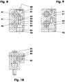
- FIGS. 8 to 10 show a base body (31) in which a two-piece clamping spindle (80) in the spindle bearing bore (41) is arranged.
- the spindle bearing bore (41) is here a smooth, finely machined through-bore, which has a Sich réellesringnut (46) at each end.
- a wire ring (48) is inserted into each securing ring groove (46) in order to axially secure the clamping spindle (80) in the base body (31).
- the clamping spindle (80) consists of a screw part (81) and a sliding part (83).
- the e.g. dumbbell-shaped screw (83) has at one end the central tool recess (77) and at the other end an internal thread (82). In between is the known from the previous variant first waist region (61).
- the clamping edge (71) has the shape of a truncated cone shell.
- the sliding part (83) is a body consisting of a cylindrical portion (84), a conical clamping flank (71) and a threaded pin (86).
- the cylindrical portion (84) which has a flattening (85) to prevent rotation, abuts in the spindle bearing bore (41) on an anti-rotation pin (89) that intersects them.
- the threaded pin (86) is screwed into the internal thread (82) of the screw (81) a piece.
Landscapes
- Engineering & Computer Science (AREA)
- Robotics (AREA)
- Mechanical Engineering (AREA)
- Manipulator (AREA)
Abstract
Description
- Die Erfindung betrifft einen Schnellspannadapter mit einer Greifelementeschnittstelle für eine Greifvorrichtung zum Adaptieren eines Greifelements an einem Schlitten oder Schwenkarm der Greifvorrichtung.
- Aus der
DE 10 2013 019 034 A1 ist eine Greifvorrichtung bekannt, die auf je einem Schlitten ein Greifelement trägt. Die Greifelemente sind über Schrauben am jeweiligen Schlitten lösbar befestigt. - Der vorliegenden Erfindung liegt die Problemstellung zugrunde, für eine Greifvorrichtung einen Adapter zu entwickeln, über den sich auswechselbare Greifelemente schnell, sicher und wartungsfrei an der Greifvorrichtung adaptieren lassen.
- Diese Problemstellung wird zum einen mit den Merkmalen des Patentanspruchs 1 gelöst. Dabei weist der Schnellspannadapter einen am Schlitten befestigbaren Grundkörper auf. Im Grundkörper ist eine mindestens einteilige Klemmspindel angeordnet. Am Greifelement sind mindenstens zwei in Ausnehmungen des Grundkörpers einsteckbare Klemmhülsen mit einem Hintergriff angeordnet. Die Klemmspindel hat pro Klemmhülse eine Klemmflanke. Die Klemmflanken der Klemmspindeln sind durch mindestens eine translatorische Bewegung mit den Hintergriffen der Klemmhülsen in Eingriff bringbar.
- Wird beispielsweise in einer Montagestation eine Greifvorrichtung eingesetzt, die jeweils nur sehr kleine Chargen montiert, ist es nachteilig, wenn das Umrüsten der Greifvorrichtung auf andere Greifelemente bzw. Greiffinger zeitaufwendig ist. Abhilfe schafft hier ein Schnellspann- bzw. Schnellwechseladapter. Dazu wird sowohl die Greifvorrichtung als auch die Greifelemente umgerüstet. An der Greifvorrichtung wird ein Adapter mit einem mechanischen, hand- oder werkzeugbedienbaren Spannmechanismus angebaut. Die Greifelemente werden mit einem zum Spannmechanismus passenden Gegenstück, z.B. Klemmhülsen, ausgerüstet.
- Die Schlitten der Greifvorrichtung haben beispielsweise drei hintereinander angeordnete Getriebe, z.B. ein Stirnradgetriebe, ein Schneckengetriebe und ein Zahnstangengetriebe. Anstelle dieser Getriebe oder zusätzlich zu mindestens einem Teil dieser Getriebe können auch Schiebekeilgetriebe, Kurven-, Hebel-, Kulissen- oder Zugmittelgetriebe eingesetzt werden.
- In den Ausführungsbeispielen werden nur Teile von Parallelgreifern gezeigt. Selbstverständlich können die meisten Teile, mit Ausnahme des Gehäuses, auch für Drei-, Vier- und Mehrbacken-, Mehrschlitten- oder Zentrischgreifer verwendet werden, so dass die dargestellte Problemlösung auch dort eingesetzt werden kann. Der Schnellspannadapter kann sowohl in Außen- als auch in Innengreifern verwendet werden.
- Selbstverständlich ist die Lösung des Problems auch auf einen Winkelgreifer übertragbar. Dazu wird der im Grundkörper der Greifvorrichtung verschiebbar geführte Schlitten durch einen greifelementetragenden Schwenkarm ersetzt, der im Grundkörper in einem Schwenkgelenk schwenkbar gelagert ist. An dem Schwenkarm wird hier der Schnellspannadapter befestigt.
- Weitere Einzelheiten der Erfindung ergeben sich aus den Unteransprüchen und der nachfolgenden Beschreibung schematisch dargestellter Ausführungsformen.
- Figur 1:
- Perspektivische Ansicht einer Parallelgreifvorrichtung mit Schnellwechseladapter;
- Figur 2:
- halbseitiger Teilschnitt zu
Figur 1 ; - Figur 3:
- Explosionszeichnung eines Schnellwechseladapters;
- Figur 4:
- Horizontalschnitt durch den perspektivisch in
Figur 1 dargestellten Schnellwechseladapter; - Figur 5:
- Horizontalschnitt durch einen nicht klemmenden Schnellwechseladapter mit einteiliger Klemmspindel;
- Figur 6:
- Horizontalschnitt wie in
Figur 5 , jedoch mit einem klemmenden Schnellwechseladapter; - Figur 7:
- Frontansicht des Schnellwechseladapters nach
Figur 5 ; - Figur 8:
- Horizontalschnitt durch einen nicht klemmenden Schnellwechseladapter mit zweiteiliger Klemmspindel;
- Figur 9:
- Horizontalschnitt wie in
Figur 8 , jedoch mit einem klemmenden Schnellwechseladapter; - Figur 10:
- vertikaler Querschnitt des Schnellwechseladapters nach
Figur 8 . - Die
Figuren 1 und2 zeigen eine Parallelgreifvorrichtung mit zwei jeweils auf Schlitten (15) sitzenden Greifbacken (1, 2). Die in ihrer Längsrichtung beweglichen Schlitten (15) sind in einem Grundkörper (11) in einer Führungsnut (12) z.B. gleitgelagert geführt. Der die Führungsnut (12) aufnehmende Grundkörper (11) umgibt ferner eine z.B. doppeltwirkende Zylinder-Kolben-Einheit (25). Die Zylinder-Kolben-Einheit wirkt über ein Doppelschiebekeilgetriebe (20) auf die Schlitten (15). Auf jedem Schlitten (15) ist ein Schnellspannadapter (30) mittels Schrauben (19) befestigt. Der Schnellspannadapter (30) weist eine mechanische Schnittstelle (61, 71; 91, 92) auf, mit der die Greifelemente (1, 2) an diesem mittels einer Einschraubbewegung präzise und schnell fixierbar sind. - Die
Figur 2 stellt die linke Hälfte der Parallelgreifvorrichtung im Teillängsschnitt dar. Der Greifbacken (1) befindet sich in geöffneter Position. Der z.B. im Wesentlichen quaderförmige Grundkörper (11) der Parallelgreifvorrichtung besteht aus einem unteren Führungsabschnitt und einem oberen Antriebsabschnitt. Die Länge des Grundkörpers (11) ist z.B. fast doppelt so lang wie seine Breite und die Grundkörperhöhe. Im Ausführungsbeispiel ist der Grundkörper (11) z.B. 151 mm lang. Der Führungsabschnitt nimmt zentral die nach unten - zu den Greifelementen (1, 2) hin - offene Führungsnut (12) auf, die z.B. einen rechteckigen Querschnitt hat. In den Seitenwandungen der Führungsnut (12) sind z.B. separate Führungsschienen eingearbeitet. - Der oberhalb des Führungsabschnittes gelegene Antriebsabschnitt nimmt im Wesentlichen die Zylinder-Kolben-Einheit (25) auf. Von der Grundkörperunterseite aus ragt eine z.B. ovale Zylinderausnehmung (13) in den Grundkörper (11) in Richtung der Führungsnut (12) hinein, vgl.
Figur 2 . Im Zentrum des Bodens der Zylinderausnehmung (13) befindet sich eine Durchgangsbohrung, die die Zylinderausnehmung (13) mit der Führungsnut (12) verbindet. Mittig weist die Durchgangsbohrung einen Einstich zur Aufnahme eines Kolbenstangendichtringes auf. - In der von einem Deckel dicht verschlossenen Zylinderausnehmung (13) ist ein ovaler Kolben (26) mit seiner Kolbenstange (27) angeordnet. Die Kolbenstange (27) ist am Kolben (26) angeschraubt. Der Kolben (26) und der Doppelschiebekeil (21) des Doppelschiebekeilgetriebes (20) bilden zusammen eine formsteife Baugruppe.
- Der Doppelschiebekeil (21) ist in der Führungsnut (12) als Teil eines Doppelschiebekeilgetriebes (20) angeordnet. Er weist an seinen stirnseitigen Enden jeweils eine im Schiebekeilwinkel abgeschrägte Stirnfläche auf, die jeweils Teil eines T-förmigen Keilstegs ist. Jeder der beiden Keilstege des Doppelschiebekeils (21) greift formschlüssig in einen in der Führungsnut (12) gelagerten Schlitten (15) ein.
- Jeder Schlitten (15) ist primär ein quaderförmiger Körper. In je einer abgeschrägten Stirnseite ist eine Keilstegnut zur Aufnahme des jeweiligen Keilstegs des Doppelschiebekeils (21) vorgesehen. Beidseitig sind z.B. je zwei Schlittenführungsnuten in den Schlitten eingearbeitet. Mit diesen Nuten ist der einzelne Schlitten (15) auf den Führungsschienen gleitgelagert.
- Auf der Oberseite jedes Schlittens (15) befindet sich eine z.B. quaderförmige Erhöhung, die bei montiertem Schlitten (15) oben um z.B. 1,2 mm - über die Grundkörperoberseite überstehend - aus der Führungsnut (12) herausragt. Die ebene Oberseite der Erhöhung hat zwei mit Zylindersenkungen ausgestattete Gewindebohrungen, an denen die Greifbacken (1, 2) lösbar befestigt werden. In den Zylindersenkungen stecken Zentrierhülsen (6) zur präzisen formschlüssigen Positionierung des Schnellspannadapters (30) auf dem jeweiligen Schlitten (15).
- Die Schlitten (15) sind hier in der Führungsnut (12), vgl. Figur 1, so hintereinander angeordnet, dass sich bei minimalem Greifbackenabstand ihre einander zugewandten Stirnseiten kontaktieren oder zumindest fast berühren. Der mittlere Bereich der Nutöffnung der Führungsnut (12) ist mit einer z.B. rechteckigen Abdeckplatte verschlossen.
- Der Schnellspannadapter (30) hat einen im Wesentlichen quaderförmigen Grundkörper (31). Zwischen der Oberseite (32) und der Unterseite (33) des Grundkörpers (31) erstrecken sich zwei z.B. mehrfach gestufte Klemmhülsenaufnahmebohrungen (51, 52), deren z.B. 15 bis 25 mm, hier 24 mm, voneinander entfernte Mittellinien parallel zur Mittellinie (7) der Greifvorrichtung (10) orientiert sind. Alle im Weiteren genannten Abmessungen beziehen sich auf die in
Figur 3 dargestellte Variante. Der dortige Grundkörper (31) hat eine Länge von 51,5 mm, eine Breite von 28,9 mm und eine Höhe von 26 mm. Er weist nach der inFigur 3 vorne liegenden kleineren Seitenfläche eine 10,5*45°-Fase auf. - Nach
Figur 2 hat jede - zur Aufnahme einer M6-Zylinder- oder Senkkopfschraube (19) geeignete - Klemmhülsenaufnahmebohrung (51, 52) zusätzlich einen Klemmhülsensitzbereich (53), einen Kopfsitzbereich (54) und einen Zentrierhülsensitzbereich (55). Der 16 mm tiefe Klemmhülsensitzbereich (53) hat einen Durchmesser von 13 mm. Der Zentrierhülsensitzbereich (55) hat bei einer Tiefe von 3 mm einen Durchmesser von 10 mm. Der Kopfsitzbereich (54) ist bezüglich seiner Geometrieform und Abmessungen an den jeweiligen Typ der Schraube (19) angepasst. - Quer zu den beiden Klemmhülsenaufnahmebohrungen (51, 52) und parallel zur Greifrichtung (9) ist im Grundkörper (31) eine Spindellagerbohrung (41) angeordnet. Sie hat einen Durchmesser von 10 mm und durchquert zwischen den beiden kleineren Seitenflächen den Grundkörper (31). Ihre Mittellinie (49) hat gegenüber den Mittellinien (59) der Klemmhülsenaufnahmebohrungen (51, 52) einen kürzesten Abstand von 9,1 mm, so dass sich die Bohrungen (51, 52) und (41) bereichsweise durchdringen. Die Spindellagerbohrung (41) ist von der dem jeweiligen Greifelement (1, 2) zugewandten Oberseite (32) 8,3 mm entfernt. An dem Ende, das im Bereich der Stirnseite liegt, die mit der Fase (39) ausgestattet ist, weist sie ein 11 mm tiefes M11-Feingewinde auf.
- Parallel zu den Klemmhülsenaufnahmebohrungen (51, 52) ist eine die Spindellagerbohrung (41) durchquerende Anschlagsstiftbohrung (57) angeordnet. Ihr kürzester Abstand zur Mittellinie (49) der Spindellagerbohrung (41) beträgt 4 mm. Die Anschlagsstiftbohrung (57) ist von der kleineren Stirnseite, die nicht die Fase (39) aufweist, 18 mm entfernt.
- Der Grundkörper (31) weist nach
Figur 3 oberhalb der Spindellagerbohrung (41) und neben den Klemmhülsenaufnahmebohrungen (51, 52) einen Grundkörperabsatz (35) auf. Der Grundkörperabsatz (35) verkleinert die Unterseite (33) so, dass beidseits der Klemmhülsenaufnahmebohrungen (51, 52) eine gleichgroße oder zumindest gleichgroße Auflagefläche gegenüber dem Schlitten (15) entsteht. Nach denFiguren 7 und10 hat der Grundkörper (31) einen weiteren Grundkörperabsatz (35), der die Unterseite (33) beidseits der Klemmhülsenaufnahmebohrungen (51, 52) auf die gleiche Weise anpasst. Eine durch die Mittellinien (59) aufgespannte Ebene halbiert somit mittig die gegenüber dem Greifelement (1,2) orientierte Auflagefläche. - Um die Greifelemente (1, 2) an den Schnellspannadapter (30) anzupassen, werden an diesen jeweils zwei 15,5 mm lange Klemmhülsen (91, 92) befestigt. Jede Klemmhülse (91, 92), deren Außendurchmesser 13 mm beträgt, ist bezüglich ihrer radial außenliegenden Gestalt ein rotationssymmetrischerer Körper, der aus einem Zylinder gefertigt wird. Im mittleren Bereich weist die einzelne Klemmhülse eine als Hintergriff dienende Taille (93) auf, die die Form einer Teiloberfläche eines Torus besitzt. An der engsten Stelle der Taille (93) misst die Klemmhülse (91, 92) 8 mm. Der Krümmungsradius der Taille (93) beträgt ca. 4,7 mm. Sein Mittelpunkt ist 7,74 mm von der am Greifelement (1, 2) anliegenden Montagestirnseite entfernt. Die Montagestirnseite weist einen 3 mm hohen Zentrieransatz (94) auf. Über diesen wird die jeweilige Klemmhülse (91, 92) am entsprechenden Greifelement (1, 2) zentriert.
- Jede Klemmhülse (91, 92) hat z.B. eine zentrale Durchgangsbohrung (95), die in der Montagestirnseite ein M6-Innengewinde (96) aufweist. Am anderen Ende der Bohrung (95) ist in diese eine Werkzeugausnehmung (97) eingearbeitet. Hier hat die Werkzeugausnehmung (97) eine sechskantförmige Querschnittsform.
- Die nach den
Figuren 3 bis 6 einteilige rotationssymmetrische Klemmspindel (60) hat im Lagerbereich einen Durchmesser von 10 mm. Die Klemmspindel (60) erstreckt sich über die gesamte Länge des Grundkörpers (31). An einem Ende weist sie ein 7 mm langes M11-Feingewinde (75) auf. NachFigur 4 weist sie am anderen Ende eine Werkzeugausnehmung (77) auf. Die Werkzeugausnehmung (77) ist, z.B. ein Innensechsrund oder ein Innenvielzahn. Alternativ kann anstelle der Werkzeugausnehmung (77) auch ein Außensechsrund, ein längs- oder kreuzgeschlitzter Kopf oder dergleichen sein. - Zwischen dem Feingewinde (75) und der Werkzeugausnehmung (77) weist die Klemmspindel (60) einen ersten und einen zweiten Taillenbereich (61, 63) auf. Beide Taillenbereiche (61, 63) sind durch einen mittleren zylindrischen Abstützbereich (64) getrennt. Auch das die Werkzeugausnehmung (77) tragende Klemmspindelende bildet einen zylindrischen Abstützbereich (62). Beide Abstützbereiche (62, 64) leiten zusammen mit dem Feingewinde (75) die in der Schnittstelle entstehenden Klemmkräfte in den Grundkörper (31) ein. Jeder Taillenbereich (61, 63) weist eine Klemmflanke (71), eine Rückflanke (72) und einen Taillengrund (73) oder Zwischenbereich auf.
- In den
Figuren 3 bis 6 sind die gewölbten Klemmflanken (71) z.B. Teilflächen eines Torus, die in einen zylindrischen Taillengrund übergehen. Der Radius der Klemmflanken (71) misst 6,5 mm, während der Taillengrund (73) einen Durchmesser von 4,8 mm hat. NachFigur 5 ist die Rückflanke (72) des ersten Taillenbereichs (61) eine ebene Bundfläche. Bei dem zweiten Taillenbereich (63) ist der Taillengrund (73) eine Teilfläche eines Torus, die in eine gestufte Rückflanke übergeht. - Wird nun gemäß der
Figuren 3 bis 6 die Klemmspindel (60) - mit einem passenden Werkzeug - über die Werkzeugausnehmung (77) an dem nachFigur 5 überstehenden Klemmspindelende, z.B. manuell, in einer Rechtsdrehung in den Grundkörper (31) eingeschraubt, legen sich die Klemmflanken (71) an den Klemmhülsen (91, 92) an. Die Rechtsdrehung der Klemmspindel (60) schraubt zum einen die Klemmflanken (71) gegen den greifelementenahen Bereich der Klemmtaillen (93) der Klemmhülsen (91, 92). Zum anderen unterstützt die Rotation der Klemmspindel (60) das Einziehen der Klemmhülse (91, 92) in die jeweilige Bohrung (3). Im geklemmten Zustand liegen die Klemmflanken (71) theoretisch jeweils über eine Punktberührung an den Klemmtaillen (93) der Klemmhülse (91, 92) an. - Zum Lösen der Greifelemente (1, 2) wird die Klemmspindel (60) in einer Linksdrehung so weit herausgeschraubt, bis bei der Variante nach den
Figuren 3 und 4 die bundartige Rückflanke (72) an einem in der Anschlagstiftbohrung (57) eingepressten Anschlagstift (79) anstößt. Bei der Variante gemäß den Figuren 5 bis 7 legt sich der dem Feingewinde (75) nachgeschaltete plane Wellenbund (76) an einem hierfür vorgesehenen Anschlagbund (44) des Grundkörpers (31) an. - Die
Figuren 8 bis 10 zeigen einen Grundkörper (31), in dem eine zweiteilige Klemmspindel (80) in der Spindellagerbohrung (41) angeordnet ist. Die Spindellagerbohrung (41) ist hier eine glatte, feinbearbeitete Durchgangsbohrung, die an jedem Ende eine Sicherungsringnut (46) aufweist. Nach dem Einsetzen der Klemmspindel (80) wird in jede Sicherungsringnut (46) ein Drahtring (48) eingelegt, um die Klemmspindel (80) im Grundkörper (31) axial zu sichern. - Die Klemmspindel (80) besteht aus einem Schraubteil (81) und einem Schiebeteil (83). Das z.B. hantelförmige Schraubteil (83) hat am einen Ende die zentrale Werkzeugausnehmung (77) und am anderen Ende ein Innengewinde (82). Dazwischen befindet sich der aus der vorherigen Variante bekannte erste Taillenbereich (61). Hier hat die Klemmflanke (71) die Form eines Kegelstumpfmantels.
- Das Schiebeteil (83) ist ein Körper, der aus einem zylindrischen Abschnitt (84), einer konischen Klemmflanke (71) und einem Gewindezapfen (86) besteht. Der zylindrische Abschnitt (84), der zur Verdrehsicherung eine Abflachung (85) hat, liegt in der Spindellagerbohrung (41) an einem diese kreuzenden Verdrehsicherungsstift (89) an. Der Gewindezapfen (86) ist in das Innengewinde (82) des Schraubteils (81) ein Stück weit eingeschraubt.
- Bei unbetätigter, offener Schnittstelle, vgl.
Figur 8 , liegen die schwimmend in der Spindellagerbohrung (41) angeordneten Teile (81) und (82) jeweils am nächstgelegenen Drahtring (48) an. - Zum Spannen eines Greifelements (1,2) werden die schon in den Klemmhülsenaufnahmebohrungen (51, 52) sitzenden Klemmhülsen (91, 92) durch eine Einschraubbewegung des Schraubteils (81) mittels der sich gegeneinander bewegenden Klemmflanken (71) festgeklemmt. Das Schraubteil (81) zieht das verdrehsicher gelagerte Schiebeteil (83) auf sich zu, bis die erforderliche Klemmkraft erreicht ist, vgl.
Figur 9 . Für das Lösen ist - wie bei der vorherigen Variante - eine entsprechende Linksdrehung erforderlich. -
- 1, 2
- Greifelemente, Greifbacken
- 3
- Befestigungsbohrung mit zwei Senkungen in (1, 2)
- 6
- Zentrierhülsen
- 7
- Mittellinie für (10) und (25)
- 9
- Greifrichtung, Schlittenverfahrrichtung
- 10
- Greifvorrichtung, Parallelgreifvorrichtung
- 11
- Grundkörper, Gehäuse
- 12
- Führungsnut
- 13
- Zylinderausnehmung
- 15
- Schlitten
- 19
- Schrauben für (30)
- 20
- Doppelschiebekeilgetriebe, Keilhakengetriebe
- 21
- Doppelschiebekeil
- 25
- Zylinder-Kolben-Einheit
- 26
- Kolben
- 27
- Kolbenstange
- 30
- Schnellspannadapter, Schnellwechseladapter
- 31
- Grundkörper, Adapterteil
- 32
- Oberseite
- 33
- Unterseite
- 34
- Spindelseite
- 35
- Grundkörperabsatz, erster
- 36
- Grundkörperabsatz, zweiter
- 37
- Absatzflanke
- 39
- Fase an kurzer Stirnseite
- 41
- Spindellagerbohrung, gestuft
- 42
- Gewinde, Feingewinde
- 43
- Gewindebohrung
- 44
- Anschlagbund
- 46
- Sicherungsringnut
- 48
- Sicherungsring, Drahtring
- 49
- Mittellinie
- 51, 52
- Klemmhülsenaufnahmebohrungen, Ausnehmung
- 53
- Klemmhülsensitzbereich
- 54
- Kopfsitzbereich
- 55
- Zentrierhülsensitzbereich
- 57
- Anschlagsstiftbohrung
- 59
- Mittellinien
- 60
- Klemmspindel, einteilig; Schnittstelle
- 61
- Taillenbereich, erster
- 62
- Abstützbereich, Spindelende
- 63
- Taillenbereich, zweiter
- 64
- Abstützbereich, Spindelmitte
- 71
- Klemmflanke, Klemmfläche, kegelig, gewölbt
- 72
- Rückflanke
- 73
- Taillengrund, Zwischenbereich
- 75
- Außengewinde, Feingewinde
- 76
- Wellenbund
- 77
- Werkzeugausnehmung
- 79
- Anschlagstift, vertikal
- 80
- Klemmspindel, zweiteilig; Schnittstelle
- 81
- Schraubteil
- 82
- Innengewinde
- 83
- Schiebeteil
- 84
- Abschnitt, zylindrisch
- 85
- Abflachung
- 86
- Gewindezapfen
- 89
- Verdrehsicherungstift, horizontal
- 91, 92
- Klemmhülsen; Schnittstelle, Adapterteil
- 93
- Klemmtaille, Hintergriff, Taille
- 94
- Zentrieransatz
- 95
- Bohrung, Sackloch, Durchgangsbohrung
- 96
- Innengewinde
- 97
- Werkzeugausnehmung
- 98
- Schrauben
Claims (7)
- Schnellspannadapter mit einer Greifelementeschnittstelle für eine Greifvorrichtung (10) zum Adaptieren eines Greifelements (1, 2) an einem Schlitten (15) oder Schwenkarm der Greifvorrichtung (10),- wobei der Schnellspannadapter (30) einen am Schlitten (15) befestigbaren Grundkörper (31) aufweist,- wobei im Grundkörper (31) eine mindestens einteilige Klemmspindel (60, 80) angeordnet ist,- wobei am Greifelement (1, 2) mindestens zwei in Ausnehmungen (41, 42) des Grundkörpers (31) einsteckbare Klemmhülsen (91, 92) mit einem Hintergriff (93) angeordnet sind,- wobei die Klemmspindel (60, 80) pro Klemmhülse (91, 92) eine Klemmflanke (71) hat,- wobei die Klemmflanken (71) der Klemmspindel (60, 80) durch mindestens eine translatorische Bewegung mit den Hintergriffen (93) der Klemmhülsen (91, 92) in Eingriff bringbar sind.
- Schnellspannadapter gemäß Anspruch 1, dadurch gekennzeichnet, dass der translatorischen Bewegung der Klemmspindel (60, 80), oder eines Teils der Klemmspindel, eine rotatorische Bewegung zwangsläufig überlagerbar ist.
- Schnellspannadapter gemäß Anspruch 1, dadurch gekennzeichnet, dass mindestens eine Klemmflanke (71) der Klemmspindel (60, 80) rotationssymmetrisch gestaltet ist.
- Schnellspannadapter gemäß Anspruch 1, dadurch gekennzeichnet, dass beide Klemmflanken (71) einer einteiligen Klemmspindel (60) in eine Richtung translatorisch bewegbar sind.
- Schnellspannadapter gemäß Anspruch 1, dadurch gekennzeichnet, dass beide Klemmflanken (71) einer zwei- oder mehrteiligen Klemmspindel (80) translatorisch aufeinanderzubewegbar sind.
- Schnellspannadapter gemäß Anspruch 5, dadurch gekennzeichnet, dass eine Klemmflanke (71) nur translatorisch bewegbar ist.
- Greifvorrichtung mit einem Schnellspannadapter nach einem der vorhergehenden Ansprüche dadurch gekennzeichnet, dass an den im Grundkörper (11) der Greifvorrichtung gelagerten Schlitten (15) oder Schwenkarmen jeweils Adapter (30) befestigt sind, in denen ein- oder aufsteckbare Greifelemente (1, 2) montierbar sind.
Applications Claiming Priority (1)
| Application Number | Priority Date | Filing Date | Title |
|---|---|---|---|
| DE102016011977.2A DE102016011977B4 (de) | 2016-10-10 | 2016-10-10 | Schnellspannadapter mit einer Greifelementeschnittstelle |
Publications (2)
| Publication Number | Publication Date |
|---|---|
| EP3305480A1 true EP3305480A1 (de) | 2018-04-11 |
| EP3305480B1 EP3305480B1 (de) | 2020-05-20 |
Family
ID=60119763
Family Applications (1)
| Application Number | Title | Priority Date | Filing Date |
|---|---|---|---|
| EP17001662.0A Active EP3305480B1 (de) | 2016-10-10 | 2017-10-10 | Schnellspannadapter mit einer greifelementeschnittstelle |
Country Status (2)
| Country | Link |
|---|---|
| EP (1) | EP3305480B1 (de) |
| DE (1) | DE102016011977B4 (de) |
Cited By (2)
| Publication number | Priority date | Publication date | Assignee | Title |
|---|---|---|---|---|
| WO2022078655A1 (en) * | 2020-10-14 | 2022-04-21 | Norgren Automation Solutions Llc | Fingers for workpiece holding devices |
| DE102021113553A1 (de) | 2021-05-26 | 2022-12-01 | Syntegon Technology Gmbh | Greifvorrichtung und System umfassend eine Greifvorrichtung |
Families Citing this family (2)
| Publication number | Priority date | Publication date | Assignee | Title |
|---|---|---|---|---|
| CN111515992B (zh) * | 2020-05-07 | 2021-07-02 | 钛昇科技股份有限公司 | 自动化手臂更换机构 |
| DE102022110877A1 (de) | 2022-05-03 | 2023-11-09 | Hoffmann Engineering Services GmbH | Montagesystem |
Citations (6)
| Publication number | Priority date | Publication date | Assignee | Title |
|---|---|---|---|---|
| EP0198379A2 (de) * | 1985-04-15 | 1986-10-22 | Traub AG | Greifvorrichtung mit auswechselbarer Greiferbacke |
| DE3715140A1 (de) * | 1987-05-07 | 1988-11-24 | Preh Indausruestung Gmbh | Handhabungseinrichtung |
| FR2720679A1 (fr) * | 1994-06-03 | 1995-12-08 | Sidel Sa | Bras de transfert et machine de fabrication de bouteilles à partir de préforme utilisant un tel bras. |
| DE60204594T2 (de) * | 2001-12-21 | 2006-03-16 | Abb Mc | Werkzeugwechselvorrichtung |
| DE102004029051C5 (de) * | 2004-06-11 | 2011-09-15 | Schunk Gmbh & Co. Kg Spann- Und Greiftechnik | Befestigungseinrichtung zur Befestigung einer Aufsatzbacke an einer beweglich gelagerten Grundbacke eines Linear- oder Zentrischgreifers und Linear- oder Zentrischgreifer |
| WO2014170355A1 (de) * | 2013-04-16 | 2014-10-23 | Schunk Gmbh & Co. Kg Spann- Und Greiftechnik | Greifvorrichtung mit lösbar anordenbaren greiffingern |
Family Cites Families (1)
| Publication number | Priority date | Publication date | Assignee | Title |
|---|---|---|---|---|
| DE102013019034B4 (de) | 2013-11-15 | 2019-05-09 | Günther Zimmer | Greifvorrichtung mit separaten Führungsschienen |
-
2016
- 2016-10-10 DE DE102016011977.2A patent/DE102016011977B4/de not_active Expired - Fee Related
-
2017
- 2017-10-10 EP EP17001662.0A patent/EP3305480B1/de active Active
Patent Citations (6)
| Publication number | Priority date | Publication date | Assignee | Title |
|---|---|---|---|---|
| EP0198379A2 (de) * | 1985-04-15 | 1986-10-22 | Traub AG | Greifvorrichtung mit auswechselbarer Greiferbacke |
| DE3715140A1 (de) * | 1987-05-07 | 1988-11-24 | Preh Indausruestung Gmbh | Handhabungseinrichtung |
| FR2720679A1 (fr) * | 1994-06-03 | 1995-12-08 | Sidel Sa | Bras de transfert et machine de fabrication de bouteilles à partir de préforme utilisant un tel bras. |
| DE60204594T2 (de) * | 2001-12-21 | 2006-03-16 | Abb Mc | Werkzeugwechselvorrichtung |
| DE102004029051C5 (de) * | 2004-06-11 | 2011-09-15 | Schunk Gmbh & Co. Kg Spann- Und Greiftechnik | Befestigungseinrichtung zur Befestigung einer Aufsatzbacke an einer beweglich gelagerten Grundbacke eines Linear- oder Zentrischgreifers und Linear- oder Zentrischgreifer |
| WO2014170355A1 (de) * | 2013-04-16 | 2014-10-23 | Schunk Gmbh & Co. Kg Spann- Und Greiftechnik | Greifvorrichtung mit lösbar anordenbaren greiffingern |
Cited By (3)
| Publication number | Priority date | Publication date | Assignee | Title |
|---|---|---|---|---|
| WO2022078655A1 (en) * | 2020-10-14 | 2022-04-21 | Norgren Automation Solutions Llc | Fingers for workpiece holding devices |
| DE102021113553A1 (de) | 2021-05-26 | 2022-12-01 | Syntegon Technology Gmbh | Greifvorrichtung und System umfassend eine Greifvorrichtung |
| WO2022248226A1 (de) | 2021-05-26 | 2022-12-01 | Syntegon Technology Gmbh | Greifvorrichtung und system umfassend eine greifvorrichtung |
Also Published As
| Publication number | Publication date |
|---|---|
| DE102016011977A1 (de) | 2018-04-12 |
| EP3305480B1 (de) | 2020-05-20 |
| DE102016011977B4 (de) | 2018-12-20 |
Similar Documents
| Publication | Publication Date | Title |
|---|---|---|
| DE865561C (de) | Werkzeugkopf | |
| DE2823766C3 (de) | Spannfutter | |
| DE69617937T2 (de) | Rotierende werkzeugmaschine | |
| EP1291120A1 (de) | Spannvorrichtung zum Ausrichten und Spannen von zwei Rohrenden | |
| DE3513453A1 (de) | Greifvorrichtung mit auswechselbarer greiferbacke | |
| EP3305480B1 (de) | Schnellspannadapter mit einer greifelementeschnittstelle | |
| EP3305479A2 (de) | Einstellbarer aufsatzadapter | |
| DE836422C (de) | Spannfutter fuer Werkzeugmaschinen | |
| EP2039450A2 (de) | Trennbare mechanische Kupplung | |
| DD297098A5 (de) | Vorrichtung zum loesbaren verbinden eines werkzeugs mit einer maschinenspindel | |
| EP0364821A2 (de) | Werkzeugadapter für eine Werkzeugmaschinenspindel | |
| DE2831140A1 (de) | Spannzange | |
| EP0287777B1 (de) | Vorrichtung zur Halterung von Werkzeugen oder Werkstücken, die einen Zylindrischen Schaft aufweisen | |
| EP2906378B1 (de) | Aufsatzvorrichtung für ein bohrsystem sowie bohrsystem zum ausbohren eines verbindungselementes | |
| EP0310936A1 (de) | Hilfswerkzeug zum gegenseitigen Verspannen von aneinanderstossenden Platten | |
| EP2998068B1 (de) | Zentrumsspanner mit schnellwechselbacken | |
| DE19907026A1 (de) | Vorrichtung zum lösbaren Verbinden eines Werkzeugs mit einer Maschinenspindel | |
| EP0215182A1 (de) | Fräs- und/oder Bohrmaschine | |
| DE1919438A1 (de) | Schnell auswechselbares Spannfutter | |
| DE3501889C1 (de) | Spannfutter für rotierende Werkzeuge | |
| DE10324670B4 (de) | Spannfutter | |
| DE102021103905B4 (de) | Spanneinheit und Spannsystem mit wenigstens einer Spanneinheit | |
| EP3815844B1 (de) | Spannbackenanordnung | |
| DE3425610A1 (de) | Vorrichtung zur auswechselbaren befestigung eines kraftbetaetigten werkstueckhalters an der drehspindel einer werkzeugmaschine | |
| DE3700841A1 (de) | Kupplungselement, insbesondere zum kraft- und formschluessigen verbinden eines werkzeugkopfes mit einem werkzeugtraeger |
Legal Events
| Date | Code | Title | Description |
|---|---|---|---|
| PUAI | Public reference made under article 153(3) epc to a published international application that has entered the european phase |
Free format text: ORIGINAL CODE: 0009012 |
|
| STAA | Information on the status of an ep patent application or granted ep patent |
Free format text: STATUS: THE APPLICATION HAS BEEN PUBLISHED |
|
| AK | Designated contracting states |
Kind code of ref document: A1 Designated state(s): AL AT BE BG CH CY CZ DE DK EE ES FI FR GB GR HR HU IE IS IT LI LT LU LV MC MK MT NL NO PL PT RO RS SE SI SK SM TR |
|
| AX | Request for extension of the european patent |
Extension state: BA ME |
|
| STAA | Information on the status of an ep patent application or granted ep patent |
Free format text: STATUS: REQUEST FOR EXAMINATION WAS MADE |
|
| 17P | Request for examination filed |
Effective date: 20181010 |
|
| RBV | Designated contracting states (corrected) |
Designated state(s): AL AT BE BG CH CY CZ DE DK EE ES FI FR GB GR HR HU IE IS IT LI LT LU LV MC MK MT NL NO PL PT RO RS SE SI SK SM TR |
|
| STAA | Information on the status of an ep patent application or granted ep patent |
Free format text: STATUS: EXAMINATION IS IN PROGRESS |
|
| 17Q | First examination report despatched |
Effective date: 20190305 |
|
| GRAP | Despatch of communication of intention to grant a patent |
Free format text: ORIGINAL CODE: EPIDOSNIGR1 |
|
| STAA | Information on the status of an ep patent application or granted ep patent |
Free format text: STATUS: GRANT OF PATENT IS INTENDED |
|
| INTG | Intention to grant announced |
Effective date: 20200302 |
|
| GRAS | Grant fee paid |
Free format text: ORIGINAL CODE: EPIDOSNIGR3 |
|
| GRAA | (expected) grant |
Free format text: ORIGINAL CODE: 0009210 |
|
| STAA | Information on the status of an ep patent application or granted ep patent |
Free format text: STATUS: THE PATENT HAS BEEN GRANTED |
|
| AK | Designated contracting states |
Kind code of ref document: B1 Designated state(s): AL AT BE BG CH CY CZ DE DK EE ES FI FR GB GR HR HU IE IS IT LI LT LU LV MC MK MT NL NO PL PT RO RS SE SI SK SM TR |
|
| REG | Reference to a national code |
Ref country code: GB Ref legal event code: FG4D Free format text: NOT ENGLISH |
|
| REG | Reference to a national code |
Ref country code: CH Ref legal event code: EP |
|
| REG | Reference to a national code |
Ref country code: DE Ref legal event code: R096 Ref document number: 502017005352 Country of ref document: DE |
|
| REG | Reference to a national code |
Ref country code: AT Ref legal event code: REF Ref document number: 1272312 Country of ref document: AT Kind code of ref document: T Effective date: 20200615 |
|
| REG | Reference to a national code |
Ref country code: LT Ref legal event code: MG4D |
|
| REG | Reference to a national code |
Ref country code: NL Ref legal event code: MP Effective date: 20200520 |
|
| PG25 | Lapsed in a contracting state [announced via postgrant information from national office to epo] |
Ref country code: PT Free format text: LAPSE BECAUSE OF FAILURE TO SUBMIT A TRANSLATION OF THE DESCRIPTION OR TO PAY THE FEE WITHIN THE PRESCRIBED TIME-LIMIT Effective date: 20200921 Ref country code: IS Free format text: LAPSE BECAUSE OF FAILURE TO SUBMIT A TRANSLATION OF THE DESCRIPTION OR TO PAY THE FEE WITHIN THE PRESCRIBED TIME-LIMIT Effective date: 20200920 Ref country code: GR Free format text: LAPSE BECAUSE OF FAILURE TO SUBMIT A TRANSLATION OF THE DESCRIPTION OR TO PAY THE FEE WITHIN THE PRESCRIBED TIME-LIMIT Effective date: 20200821 Ref country code: NO Free format text: LAPSE BECAUSE OF FAILURE TO SUBMIT A TRANSLATION OF THE DESCRIPTION OR TO PAY THE FEE WITHIN THE PRESCRIBED TIME-LIMIT Effective date: 20200820 Ref country code: SE Free format text: LAPSE BECAUSE OF FAILURE TO SUBMIT A TRANSLATION OF THE DESCRIPTION OR TO PAY THE FEE WITHIN THE PRESCRIBED TIME-LIMIT Effective date: 20200520 Ref country code: LT Free format text: LAPSE BECAUSE OF FAILURE TO SUBMIT A TRANSLATION OF THE DESCRIPTION OR TO PAY THE FEE WITHIN THE PRESCRIBED TIME-LIMIT Effective date: 20200520 Ref country code: FI Free format text: LAPSE BECAUSE OF FAILURE TO SUBMIT A TRANSLATION OF THE DESCRIPTION OR TO PAY THE FEE WITHIN THE PRESCRIBED TIME-LIMIT Effective date: 20200520 |
|
| PG25 | Lapsed in a contracting state [announced via postgrant information from national office to epo] |
Ref country code: BG Free format text: LAPSE BECAUSE OF FAILURE TO SUBMIT A TRANSLATION OF THE DESCRIPTION OR TO PAY THE FEE WITHIN THE PRESCRIBED TIME-LIMIT Effective date: 20200820 Ref country code: HR Free format text: LAPSE BECAUSE OF FAILURE TO SUBMIT A TRANSLATION OF THE DESCRIPTION OR TO PAY THE FEE WITHIN THE PRESCRIBED TIME-LIMIT Effective date: 20200520 Ref country code: LV Free format text: LAPSE BECAUSE OF FAILURE TO SUBMIT A TRANSLATION OF THE DESCRIPTION OR TO PAY THE FEE WITHIN THE PRESCRIBED TIME-LIMIT Effective date: 20200520 Ref country code: RS Free format text: LAPSE BECAUSE OF FAILURE TO SUBMIT A TRANSLATION OF THE DESCRIPTION OR TO PAY THE FEE WITHIN THE PRESCRIBED TIME-LIMIT Effective date: 20200520 |
|
| PG25 | Lapsed in a contracting state [announced via postgrant information from national office to epo] |
Ref country code: AL Free format text: LAPSE BECAUSE OF FAILURE TO SUBMIT A TRANSLATION OF THE DESCRIPTION OR TO PAY THE FEE WITHIN THE PRESCRIBED TIME-LIMIT Effective date: 20200520 Ref country code: NL Free format text: LAPSE BECAUSE OF FAILURE TO SUBMIT A TRANSLATION OF THE DESCRIPTION OR TO PAY THE FEE WITHIN THE PRESCRIBED TIME-LIMIT Effective date: 20200520 |
|
| PG25 | Lapsed in a contracting state [announced via postgrant information from national office to epo] |
Ref country code: DK Free format text: LAPSE BECAUSE OF FAILURE TO SUBMIT A TRANSLATION OF THE DESCRIPTION OR TO PAY THE FEE WITHIN THE PRESCRIBED TIME-LIMIT Effective date: 20200520 Ref country code: ES Free format text: LAPSE BECAUSE OF FAILURE TO SUBMIT A TRANSLATION OF THE DESCRIPTION OR TO PAY THE FEE WITHIN THE PRESCRIBED TIME-LIMIT Effective date: 20200520 Ref country code: CZ Free format text: LAPSE BECAUSE OF FAILURE TO SUBMIT A TRANSLATION OF THE DESCRIPTION OR TO PAY THE FEE WITHIN THE PRESCRIBED TIME-LIMIT Effective date: 20200520 Ref country code: RO Free format text: LAPSE BECAUSE OF FAILURE TO SUBMIT A TRANSLATION OF THE DESCRIPTION OR TO PAY THE FEE WITHIN THE PRESCRIBED TIME-LIMIT Effective date: 20200520 Ref country code: EE Free format text: LAPSE BECAUSE OF FAILURE TO SUBMIT A TRANSLATION OF THE DESCRIPTION OR TO PAY THE FEE WITHIN THE PRESCRIBED TIME-LIMIT Effective date: 20200520 Ref country code: SM Free format text: LAPSE BECAUSE OF FAILURE TO SUBMIT A TRANSLATION OF THE DESCRIPTION OR TO PAY THE FEE WITHIN THE PRESCRIBED TIME-LIMIT Effective date: 20200520 |
|
| REG | Reference to a national code |
Ref country code: DE Ref legal event code: R097 Ref document number: 502017005352 Country of ref document: DE |
|
| PG25 | Lapsed in a contracting state [announced via postgrant information from national office to epo] |
Ref country code: PL Free format text: LAPSE BECAUSE OF FAILURE TO SUBMIT A TRANSLATION OF THE DESCRIPTION OR TO PAY THE FEE WITHIN THE PRESCRIBED TIME-LIMIT Effective date: 20200520 Ref country code: SK Free format text: LAPSE BECAUSE OF FAILURE TO SUBMIT A TRANSLATION OF THE DESCRIPTION OR TO PAY THE FEE WITHIN THE PRESCRIBED TIME-LIMIT Effective date: 20200520 |
|
| PLBE | No opposition filed within time limit |
Free format text: ORIGINAL CODE: 0009261 |
|
| STAA | Information on the status of an ep patent application or granted ep patent |
Free format text: STATUS: NO OPPOSITION FILED WITHIN TIME LIMIT |
|
| 26N | No opposition filed |
Effective date: 20210223 |
|
| PG25 | Lapsed in a contracting state [announced via postgrant information from national office to epo] |
Ref country code: SI Free format text: LAPSE BECAUSE OF FAILURE TO SUBMIT A TRANSLATION OF THE DESCRIPTION OR TO PAY THE FEE WITHIN THE PRESCRIBED TIME-LIMIT Effective date: 20200520 |
|
| REG | Reference to a national code |
Ref country code: CH Ref legal event code: PL |
|
| PG25 | Lapsed in a contracting state [announced via postgrant information from national office to epo] |
Ref country code: LU Free format text: LAPSE BECAUSE OF NON-PAYMENT OF DUE FEES Effective date: 20201010 Ref country code: MC Free format text: LAPSE BECAUSE OF FAILURE TO SUBMIT A TRANSLATION OF THE DESCRIPTION OR TO PAY THE FEE WITHIN THE PRESCRIBED TIME-LIMIT Effective date: 20200520 |
|
| REG | Reference to a national code |
Ref country code: BE Ref legal event code: MM Effective date: 20201031 |
|
| PG25 | Lapsed in a contracting state [announced via postgrant information from national office to epo] |
Ref country code: LI Free format text: LAPSE BECAUSE OF NON-PAYMENT OF DUE FEES Effective date: 20201031 Ref country code: CH Free format text: LAPSE BECAUSE OF NON-PAYMENT OF DUE FEES Effective date: 20201031 Ref country code: BE Free format text: LAPSE BECAUSE OF NON-PAYMENT OF DUE FEES Effective date: 20201031 |
|
| PG25 | Lapsed in a contracting state [announced via postgrant information from national office to epo] |
Ref country code: IE Free format text: LAPSE BECAUSE OF NON-PAYMENT OF DUE FEES Effective date: 20201010 |
|
| PG25 | Lapsed in a contracting state [announced via postgrant information from national office to epo] |
Ref country code: TR Free format text: LAPSE BECAUSE OF FAILURE TO SUBMIT A TRANSLATION OF THE DESCRIPTION OR TO PAY THE FEE WITHIN THE PRESCRIBED TIME-LIMIT Effective date: 20200520 Ref country code: MT Free format text: LAPSE BECAUSE OF FAILURE TO SUBMIT A TRANSLATION OF THE DESCRIPTION OR TO PAY THE FEE WITHIN THE PRESCRIBED TIME-LIMIT Effective date: 20200520 Ref country code: CY Free format text: LAPSE BECAUSE OF FAILURE TO SUBMIT A TRANSLATION OF THE DESCRIPTION OR TO PAY THE FEE WITHIN THE PRESCRIBED TIME-LIMIT Effective date: 20200520 |
|
| PG25 | Lapsed in a contracting state [announced via postgrant information from national office to epo] |
Ref country code: MK Free format text: LAPSE BECAUSE OF FAILURE TO SUBMIT A TRANSLATION OF THE DESCRIPTION OR TO PAY THE FEE WITHIN THE PRESCRIBED TIME-LIMIT Effective date: 20200520 |
|
| REG | Reference to a national code |
Ref country code: AT Ref legal event code: MM01 Ref document number: 1272312 Country of ref document: AT Kind code of ref document: T Effective date: 20221010 |
|
| PG25 | Lapsed in a contracting state [announced via postgrant information from national office to epo] |
Ref country code: AT Free format text: LAPSE BECAUSE OF NON-PAYMENT OF DUE FEES Effective date: 20221010 |
|
| PGFP | Annual fee paid to national office [announced via postgrant information from national office to epo] |
Ref country code: DE Payment date: 20251014 Year of fee payment: 9 |
|
| PGFP | Annual fee paid to national office [announced via postgrant information from national office to epo] |
Ref country code: GB Payment date: 20251024 Year of fee payment: 9 |
|
| PGFP | Annual fee paid to national office [announced via postgrant information from national office to epo] |
Ref country code: IT Payment date: 20251030 Year of fee payment: 9 |
|
| PGFP | Annual fee paid to national office [announced via postgrant information from national office to epo] |
Ref country code: FR Payment date: 20251024 Year of fee payment: 9 |