EP3305530A1 - Cartouche d'encre et son procédé d'installation - Google Patents
Cartouche d'encre et son procédé d'installation Download PDFInfo
- Publication number
- EP3305530A1 EP3305530A1 EP16838518.5A EP16838518A EP3305530A1 EP 3305530 A1 EP3305530 A1 EP 3305530A1 EP 16838518 A EP16838518 A EP 16838518A EP 3305530 A1 EP3305530 A1 EP 3305530A1
- Authority
- EP
- European Patent Office
- Prior art keywords
- ink cartridge
- plane
- axis
- axis direction
- engagement portion
- Prior art date
- Legal status (The legal status is an assumption and is not a legal conclusion. Google has not performed a legal analysis and makes no representation as to the accuracy of the status listed.)
- Granted
Links
Images




Classifications
-
- B—PERFORMING OPERATIONS; TRANSPORTING
- B41—PRINTING; LINING MACHINES; TYPEWRITERS; STAMPS
- B41J—TYPEWRITERS; SELECTIVE PRINTING MECHANISMS, i.e. MECHANISMS PRINTING OTHERWISE THAN FROM A FORME; CORRECTION OF TYPOGRAPHICAL ERRORS
- B41J2/00—Typewriters or selective printing mechanisms characterised by the printing or marking process for which they are designed
- B41J2/005—Typewriters or selective printing mechanisms characterised by the printing or marking process for which they are designed characterised by bringing liquid or particles selectively into contact with a printing material
- B41J2/01—Ink jet
- B41J2/17—Ink jet characterised by ink handling
- B41J2/175—Ink supply systems ; Circuit parts therefor
- B41J2/17503—Ink cartridges
-
- B—PERFORMING OPERATIONS; TRANSPORTING
- B41—PRINTING; LINING MACHINES; TYPEWRITERS; STAMPS
- B41J—TYPEWRITERS; SELECTIVE PRINTING MECHANISMS, i.e. MECHANISMS PRINTING OTHERWISE THAN FROM A FORME; CORRECTION OF TYPOGRAPHICAL ERRORS
- B41J2/00—Typewriters or selective printing mechanisms characterised by the printing or marking process for which they are designed
- B41J2/005—Typewriters or selective printing mechanisms characterised by the printing or marking process for which they are designed characterised by bringing liquid or particles selectively into contact with a printing material
- B41J2/01—Ink jet
- B41J2/17—Ink jet characterised by ink handling
- B41J2/175—Ink supply systems ; Circuit parts therefor
-
- B—PERFORMING OPERATIONS; TRANSPORTING
- B41—PRINTING; LINING MACHINES; TYPEWRITERS; STAMPS
- B41J—TYPEWRITERS; SELECTIVE PRINTING MECHANISMS, i.e. MECHANISMS PRINTING OTHERWISE THAN FROM A FORME; CORRECTION OF TYPOGRAPHICAL ERRORS
- B41J2/00—Typewriters or selective printing mechanisms characterised by the printing or marking process for which they are designed
- B41J2/005—Typewriters or selective printing mechanisms characterised by the printing or marking process for which they are designed characterised by bringing liquid or particles selectively into contact with a printing material
- B41J2/01—Ink jet
- B41J2/17—Ink jet characterised by ink handling
- B41J2/175—Ink supply systems ; Circuit parts therefor
- B41J2/17503—Ink cartridges
- B41J2/1752—Mounting within the printer
-
- B—PERFORMING OPERATIONS; TRANSPORTING
- B41—PRINTING; LINING MACHINES; TYPEWRITERS; STAMPS
- B41J—TYPEWRITERS; SELECTIVE PRINTING MECHANISMS, i.e. MECHANISMS PRINTING OTHERWISE THAN FROM A FORME; CORRECTION OF TYPOGRAPHICAL ERRORS
- B41J2/00—Typewriters or selective printing mechanisms characterised by the printing or marking process for which they are designed
- B41J2/005—Typewriters or selective printing mechanisms characterised by the printing or marking process for which they are designed characterised by bringing liquid or particles selectively into contact with a printing material
- B41J2/01—Ink jet
- B41J2/17—Ink jet characterised by ink handling
- B41J2/175—Ink supply systems ; Circuit parts therefor
- B41J2/17503—Ink cartridges
- B41J2/17553—Outer structure
Definitions
- the present invention relates to the field of printers, and specifically, to an accessory ink cartridge of an ink-jet printer, and in particular, to an ink cartridge and a method of installing same.
- Ink-jet printers are relatively commonly used printing tools. Although laser printers are popularized currently, maintenance costs of the laser printers are relatively high. Therefore, the ink-jet printers still account for a large market share, and especially, are used in locations such as homes, shops, and offices.
- An ink-jet printer has an ink cartridge and an ink cartridge holder.
- ink-jet printer there are many manners for engaging the ink cartridge with the ink cartridge holder.
- commonly used manners include jointing and snap-fit.
- FIG. 30 in Chinese Patent CN201510060960.1 an ink cartridge is fixed by engaging a first apparatus side engagement portion on a movable lever of a printer holder with a first ink cartridge side engagement portion of the ink cartridge.
- a push portion of the movable lever is pushed, so that the first ink cartridge side engagement portion of the ink cartridge is separated from the first apparatus side engagement portion, to take out the ink cartridge from the holder.
- such an engagement manner has some technical problems.
- a rotating shaft of the movable lever is located between the push portion and the first apparatus side engagement portion, a distance between the first apparatus side engagement portion and the rotating shaft is denoted by d, and a distance between the push portion and the rotating shaft is denoted by t.
- the size of the movable lever needs to be reduced, and d ⁇ t may occur.
- the lever in a process of taking out the ink cartridge, the lever needs to rotate counterclockwise. During the counterclockwise rotation, the first apparatus side engagement portion moves towards a -Z-axis direction at the same time. Consequently, the ink cartridge needs to move downward first, to enable the first ink cartridge side engagement portion to be separated from the first apparatus side engagement portion. This manner causes damage to a stylus or a chip.
- the -Z-axis direction described herein is a direction that points from another plane opposite to a plane in which an ink supply port is located to the plane in which the ink supply port is located.
- the first ink cartridge side engagement portion is close to a second ink cartridge side engagement portion on a Z-axis, a center spin axis that passes through the first ink cartridge side engagement portion and the second ink cartridge side engagement portion and that is perpendicular to a YZ plane is easily formed.
- a moving direction of the ink cartridge holder is a Y-axis direction.
- a force that is provided in the Y-axis direction by flowing air is applied to the ink cartridge. Consequently, the ink cartridge may shake around the center spin axis that is perpendicular to the YZ plane, causing unstable fixation of the ink cartridge, poor contact of the chip, or incomplete sealing of the ink supply port.
- an ink cartridge includes at least a housing 11 and a handle 12, and the housing includes an ink supply port 111, where a plane in which the ink supply port 111 is located is a first plane 1a, and another plane of the ink cartridge opposite to the first plane is a second plane 1b; a direction along a longer side on the first plane is an X-axis; a direction along a shorter side on the first plane is a Y-axis; and an axis that is perpendicular to both the X-axis and the Y-axis is a Z-axis.
- the handle 12 includes: an operation portion 121, an engagement portion 122, and a support portion 123 that are disposed in sequence in a Z-axis direction, and a distance from the engagement portion 122 to the support portion 123 and a distance from the operation portion 121 to the support portion 123 should meet the following formula: 2/3t ⁇ d ⁇ t, where t is the distance from the operation portion 121 to the support portion 123 in the Z-axis direction, and d is the distance from the engagement portion 122 to the support portion 123 in the Z-axis direction.
- the ink cartridge further includes a chip 13, a direction in which the ink supply port 111 faces towards the chip 13 is a +X-axis, and a direction in which the first plane 1a faces towards the second plane 1b is a +Z-axis direction, where a surface of the ink cartridge on a -X-axis side is a fourth plane 1d, and a surface opposite to the fourth plane 1d is a third plane 1c.
- An inclined area 14 connecting the third plane 1c and the first plane 1a is disposed in -Z-axis and +X-axis directions of the third plane 1c; and the handle 12 is located on a +X-axis side of the housing 11, and is disposed on the inclined area 14, where the handle 12 includes the support portion 123, the operation portion 121, and the engagement portion 122 in sequence in the +Z-axis direction, and the operation portion 121 and the engagement portion 122 extend towards the +X-axis and +Z-axis directions relative to the support portion 123.
- the handle 12 further includes a guiding portion 124, where the guiding portion 124 is disposed in the +X-axis direction of the support portion 123, and the guiding portion 124 is located in the -Z-axis direction of the engagement portion 122.
- At least one guiding surface 1242 extending towards the +X-axis direction is disposed in a Y-axis direction of the guiding portion 124, at least one compression surface 1241 extending towards the Y-axis direction is disposed in the +X-axis direction of the guiding surface 1242, and the compression surface 1241 is connected to the guiding surface 1242.
- the compression surface 1241 is any one of the following structures: two or more strip areas that are disposed in parallel; a plane; a plane inclined at an angle to the handle; a serrated area; a wavy area; or an irregularly shaped area.
- the handle further includes a support rib 125, the support rib 125 is disposed between the operation portion 121 and the engagement portion 122, and the support rib 125 is connected to the operation portion 121 and the engagement portion 122 separately.
- an outer edge of the support rib 125 retreats into outer edges of the operation portion 121 and the engagement portion 122.
- an upper part of the engagement portion 122 is connected to the support rib 125, and the engagement portion 122 is neither connected to the operation portion 121 nor connected to the support portion 123.
- the handle 12 is capable of deflecting by using an end of the support portion 123 in the -Z-axis direction as a shaft, and a deflection angle meets the following formula: -25° ⁇ a ⁇ 25°, where a is the deflection angle.
- the support portion 123 is bent and extends in the +Z-axis and +X-axis directions to form a first extension portion 1231
- the first extension portion 1231 is bent and extends again in the +Z-axis and +X-axis directions to form a second extension portion 1232
- the operation portion 121 and the engagement portion 122 are disposed on a combination of the first extension portion 1231 and the second extension portion 1232.
- an acute angle a1 formed between the first extension portion 1231 and the support portion 123 is between 16° and 36°
- an acute angle a2 formed between the second extension portion 1232 and the first extension portion 1231 is between 39° and 69°.
- the ink cartridge further includes a protective cover 16, the protective cover 16 has a restriction portion 163 on the +X-axis side, and the housing 11 has a restricted portion 163'; and when the protective cover 16 is installed on the housing 11, the restriction portion 163 and the restricted portion 163' are jointed to each other, and the restriction portion 163 and the restricted portion 163' are located between the ink supply port 111 and the chip 13.
- an ink cartridge with a replaceable portion including the ink cartridge according to any one of the foregoing descriptions, where the ink cartridge further includes a replaceable portion 2, the replaceable portion 2 is detachably connected to the housing 11, and the replaceable portion 2 is located in the +X-axis direction of the housing 11; and the handle 12 and the chip 13 are disposed on the replaceable portion 2.
- an ink cartridge connected to an ink cartridge holder where the ink cartridge is connected to an ink cartridge holder 3, the ink cartridge holder 3 is disposed in a printer, and a handle of the ink cartridge includes: an operation portion 121, an engagement portion 122, and a support portion 123 that are disposed in sequence in a Z-axis direction.
- a distance from the engagement portion 122 to the support portion 123 and a distance from the operation portion 121 to the support portion 123 meets a formula: 2/3t ⁇ d ⁇ t; and the engagement portion 122 and the ink cartridge holder 3 are engaged with each other, where the ink cartridge holder 3 includes at least a lever body 31, a rotating shaft 32, and a lever opening 33, the engagement portion 122 and the lever opening 33 are engaged with each other, and a sectional area of the engagement portion 122 is less than or equal to an opening size of the lever opening 33.
- the handle 12 is located on a +X-axis side of the housing 11, and is disposed on an inclined area 14, where the handle 12 includes the support portion 123, the operation portion 121, and the engagement portion 122 in sequence in a +Z-axis direction, and the operation portion 121 and the engagement portion 122 extend towards +X-axis and +Z-axis directions relative to the support portion 123.
- the handle 12 of the ink cartridge connected to the ink cartridge holder further includes a support rib 125, the support rib 125 is disposed between the operation portion 121 and the engagement portion 122, and the support rib 125 is connected to the operation portion 121 and the engagement portion 122 separately. More preferably, an outer edge of the support rib 125 retreats into outer edges of the operation portion 121 and the engagement portion 122.
- the handle 12 of the ink cartridge connected to the ink cartridge holder is capable of deflecting by using an end of the support portion 123 in a -Z-axis direction as a shaft, and a deflection angle is -25° ⁇ a ⁇ 25°.
- the support portion 123 of the handle 12 of the ink cartridge connected to the ink cartridge holder is bent and extends in the +Z-axis and +X-axis directions to form a first extension portion 1231
- the first extension portion 1231 is bent and extends again in the +Z-axis and +X-axis directions to form a second extension portion 1232
- the operation portion 121 and the engagement portion 122 are disposed on a combination of the first extension portion 1231 and the second extension portion 1232.
- An acute angle a1 formed between the first extension portion 1231 and the support portion 123 is between 16° and 36°
- an acute angle a2 formed between the second extension portion 1232 and the first extension portion 1231 is between 39° and 69°.
- the ink cartridge connected to the ink cartridge holder further includes a protective cover 16, the protective cover 16 has a restriction portion 163 on the +X-axis side, and the housing 11 has a restricted portion 163'; and when the protective cover 16 is installed on the housing 11, the restriction portion 163 and the restricted portion 163' are jointed to each other, and the restriction portion 163 and the restricted portion 163' are located between an ink supply port 111 and a chip 13.
- At least one guiding rib 311 is disposed on the lever body 31, a guiding surface 1242 of the ink cartridge is attached to an inner surface of the guiding rib 311, and a compression surface 1241 of the ink cartridge is in contact with the lever body 31, and drives the lever body 31 to rotate around the rotating shaft 32.
- the ink cartridge holder 3 further includes a slot 34, and the slot 34 and a latching portion 15 of the ink cartridge are engaged with each other.
- a method for installing an ink cartridge used to fix the ink cartridge to an ink cartridge holder, and including the following steps:
- the step b further includes the following steps:
- the method further includes step a': removing a protective cover from the ink cartridge, and moving the ink cartridge to the ink cartridge holder.
- the handle is disposed on the ink cartridge, and the engagement portion is disposed at a corresponding position of the handle.
- configuration of the engagement portion meets a technical specification, so that the ink cartridge and an ink cartridge holder suitable for the ink cartridge are stably fixed, and the ink cartridge is easily taken out, thereby reducing damage to a stylus and a chip of the ink cartridge, and avoiding ink leakage and ink splashing.
- the ink cartridge is precisely positioned by using the guiding portion on the ink cartridge, to prevent installing the ink cartridge at an incorrect position.
- the ink cartridge provided in the present invention is easy to operate, has a long service life and a simple production process, and can be manufactured in batches.
- FIG. 1 is a schematic structural diagram of an ink cartridge according to a first specific implementation of the present invention. It is understood by a person skilled in the art that the figure is only a schematic diagram showing the entire effect of the ink cartridge. To better describe specific implementations of the present invention, other parts are not shown in the figure, but this does not mean that the parts do not exist in the present invention. Details are not described herein. Specifically, as shown in FIG. 1, FIG. 1 is a three-dimensional structural effect diagram of the ink cartridge.
- the ink cartridge includes at least a housing 11 and a handle 12.
- the housing includes an ink supply port 111. It is understood by a person skilled in the art that the ink cartridge is used to store ink and is an apparatus used for printing in cooperation with a printer device.
- the housing 11 is of a cuboid shape. However, in another variation, to adapt to and cooperate with a printer device or to achieve the aesthetic appearance, the housing 11 may alternatively be of a polygonal shape, an elliptical shape, or the like. This does not affect the technical solution of the present invention, and details are not described herein.
- the ink cartridge further includes the handle 12, and the handle 12 is located on a side of the ink cartridge. All these will be described in detail in the specific implementations below.
- a plane in which the ink supply port 111 is located is a first plane
- another plane of the ink cartridge opposite to the first plane is a second plane.
- the first plane is the bottom of the ink cartridge
- the second plane is the top of the ink cartridge.
- a direction along a longer side on the first plane is an X-axis
- a direction along a shorter side on the first plane is a Y-axis
- an axis that is perpendicular to both the X-axis and the Y-axis is a Z-axis.
- FIG. 2 and FIG. 3 are detailed views of the handle 12.
- the handle 12 includes: an operation portion 121, an engagement portion 122, and a support portion 123.
- the operation portion 121 is used to push the handle 12 when a user takes out the ink cartridge, to drive the handle 12 to rotate.
- the engagement portion 122 is used to fix the ink cartridge when the ink cartridge is installed onto the ink cartridge holder 3, to prevent the ink cartridge from moving vertically.
- the handle 12 rotates by using an end of the support portion 123 close to the chip 13 as a shaft, so that the ink cartridge is conveniently installed or taken out.
- a distance from the engagement portion 122 to the support portion 123 and a distance from the operation portion 121 to the support portion 123 should meet the formula: 2/3t ⁇ d ⁇ t, where t is the distance from the operation portion to the support portion in a Z-axis direction, and d is the distance from the engagement portion to the support portion in the Z-axis direction. It is understood by a person skilled in the art that, as shown in FIG. 1 , the engagement portion 122 is located under the operation portion 121 in the Z direction.
- t is defined as a distance from a center line of the operation portion 121 perpendicular to the Z-axis to a lowermost end of the support portion 123 in the Z-axis direction
- d is defined as a distance from a center line of the engagement portion 122 perpendicular to the Z-axis to the lowermost end of the support portion 123 in the Z-axis direction.
- d 0.825t.
- the distance d from the operation portion 121 to the support portion 123 in the Z-axis direction is 15.47 mm
- the distance from the engagement portion 122 to the support portion 123 in the Z-axis direction is 12.77 mm.
- a distance between the engagement portion 122 and the operation portion 121 is 2.7 mm. It may be learned from the foregoing specific values that the distance between the engagement portion 122 and the operation portion 121 is very small. During actual use, the engagement portion 122 can be easily controlled by using the operation portion 121. In addition, the operation portion 121 is further away from the support portion 123. According to the torque balance principle, pushing the operation portion 121 is more effort-saving than directly pushing the engagement portion 122.
- the ink cartridge further includes a chip 13.
- the chip 13 is used to record an ink volume of the ink cartridge, monitor usage frequency of the ink cartridge, and the like. It is understood by a person skilled in the art that, the ink cartridge may be provided with the chip 13, or may not be provided with the chip 13. This does not affect the technical solution of the present invention, and details are not described herein.
- the housing 11 includes a first plane 1a, a second plane 1b, a third plane 1c, and a fourth plane 1d.
- the first plane 1a is opposite to the second plane 1b
- the third plane 1c is opposite to the fourth plane 1d.
- a plane in which the ink supply port 111 is located is the first plane 1a
- a direction in which the ink supply port 111 faces towards the chip 13 is a +X-axis
- a direction in which the first plane 1a points to the second plane 1b is a +Z-axis direction
- a direction that is formed by rotating a +X-axis direction counterclockwise by 90° in an XY plane is a +Y-axis direction.
- a plane located on a -X-axis side of the ink cartridge is the fourth plane 1d
- a plane opposite to the fourth plane 1d is the third plane 1c.
- An inclined area 14 connecting the third plane 1c and the first plane 1a is disposed in -Z-axis and +X-axis directions of the third plane 1c.
- An end of the support portion 123 is disposed on the inclined area 14, so that the handle 12 is disposed on the inclined area 14.
- the handle 12 is located on a +X-axis side of the housing 1, the operation portion 121 and the engagement portion 122 are located in +Z-axis direction of the support portion 123, and the engagement portion 122 and the operation portion 121 extend towards the +X-axis and +Z-axis directions relative to the support portion 123.
- the engagement portion 122 and the operation portion 121 are disposed in parallel.
- the engagement portion 122 and the operation portion 121 may not be disposed in parallel.
- parts of the handle 12 in the +Z-axis direction are the support portion 123, the engagement portion 122, and the operation portion 121 in sequence.
- the handle 12 further includes a guiding portion 124.
- the guiding portion 124 is disposed in the +X-axis direction of the support portion 123, and the guiding portion 124 is located in the -Z-axis direction of the engagement portion 122. It is understood by a person skilled in the art that the guiding portion 124 can fix the ink cartridge more easily.
- the guiding portion 124 has a guiding surface 1242 and compression surface 1241.
- the guiding surface 1242 has a guiding function during installation of the cartridge, and the compression surface 1241 can apply, during installation of the cartridge, a compression force to a part that cooperates with the guiding portion 1242.
- the guiding portion 124 may be an independent part, or may be an integral part that is formed with the handle 12 by means of integral injection molding. Details are not described herein.
- At least one guiding surface 1242 extending towards the +X-axis direction is disposed in a Y-axis direction of the guiding portion 124
- at least one compression surface 1241 extending towards the Y-axis direction is disposed in the +X-axis direction of the guiding surface 1242
- the compression surface 1241 is connected to the guiding surface 1242.
- three protruded strip structures are disposed on the guiding portion 124.
- One of the three protruded strip structures is used as an example.
- the strip structure extends in the -Z-axis direction of the guiding portion 124, and the strip structure has two side areas in the Y-axis direction.
- the two side areas are two guiding surfaces 1242, and the two guiding surfaces 1242 is connected to one compression surface 1241 in the +X direction. More specifically, the two guiding surfaces 1242 are two areas of the guiding portion 124 in an XZ plane, and the compression surface 1241 is an area of the guiding portion 124 in a YZ plane. It is understood by a person skilled in the art that there are three strip structures in total in FIG. 4 . That is, the guiding portion includes a total of six guiding surfaces 1242 and three compression surfaces 1241. In some other variations, of the number of strip structures may be changed, or the shape of the strip structure may be changed, thereby changing the number of guiding surfaces 1242 and compression surfaces 1241.
- the shape of the compression surface 1241 is not only limited to the shape shown in FIG. 2 .
- the compression surface 1241 may alternatively be two or more strip areas that are disposed in parallel, an integral plane, a plane inclined at an angle to the handle, a serrated area, a wavy area, or an irregularly shaped area.
- the handle 12 further includes a support rib 125, and the support rib 125 is disposed between the operation portion 121 and the engagement portion 122. It is understood by a person skilled in the art that the support rib 125 is considered as a part for strengthening fixation.
- the support rib 125 is connected and fixed between the operation portion 121 and the engagement portion 122, so that the strength of the engagement portion is strengthened. Further, the service life of the engagement portion is increased.
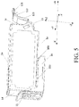
- the support rib 125 retreats into outer edges of the operation portion 121 and the engagement portion 122. It is understood by a person skilled in the art that, as shown in FIG. 4 , the support rib 125 is preferably a cuboid structure. The length of the support rib 125 relative to the support portion 123 in the +X-axis direction is less than the lengths of the operation portion 121 and the engagement portion 122 relative to the support portion 123 in the +X-axis direction.
- the support rib 125 is located on the -X-axis side of the outer edge of the operation portion 121 in the +X-axis direction, and the support rib 125 is located on the -X-axis side of the outer edge of the engagement portion 122 in the +X-axis direction.
- an integral structure formed by the support rib 125, the operation portion 121, and the engagement portion 122 has the aesthetic appearance and a long service life, and the support rib 125 does not affect work of the engagement portion 122.
- the support rib 125 may alternatively be of a cylinder or another shape. This does not affect essential content of the present invention, and details are not described herein again.
- the engagement portion 122 is not directly connected to the operation portion 121 and the support portion 123, and the engagement portion 122 is connected to the operation portion 121 by using the support rib 125. That is, the operation portion 121, the support rib 125, and the engagement portion 122 are disposed in sequence in the -Z-axis direction.
- FIG. 4 shows one support rib 125. In some variations, there may be a plurality of support ribs 125. All of those can achieve the objective of the present invention, and details are not described herein.
- the handle 12 is capable of deflecting by using an end of the support portion 123 in the -Z-axis direction as a shaft.
- a deflection angle a meets the following formula: -25° ⁇ a ⁇ 25°.
- the deflection angle a is defined as 0°.
- the deflection may be implemented in various manners. For example, a rotating shaft is disposed at an end of the support portion 123 in the -Z-axis direction, and the handle may deflect about the rotating shaft of the support portion 123.
- the handle 12 may be made of a deformable material.
- the handle 12 is deflected by applying an external force. Further, to deflect the handle 12 more easily by pushing the operation portion 121, and to increase the service life of the handle 12, preferably, the deflection angle a is most appropriately between -10° and 10°.
- the deflection angle is defined based on that the deflection angle is 0° when the handle 12 is at ease.
- the handle 12 is in a " " shape.
- the handle may be in a " ⁇ ” shape.
- a deformable part or a rotating shaft may be correspondingly disposed below the handle.
- the handle may alternatively be in a " ⁇ ” shape, a " " shape, a “ “ shape, or another shape.
- the engagement portion may be disposed at different positions according to different shapes of the handle. For example, one side of a Y-shaped handle is connected to the housing by using two points, and the other side in the +X-axis and +Z-axis directions is provided with the engagement portion. However, this does not affect the technical solution of the present invention, and details are not described herein.
- the support portion 123 of the handle 12 is bent and extends in the +Z-axis and +X-axis directions to form a first extension portion 1231
- the first extension portion 1231 is bent and extends again in the +Z-axis and +X-axis directions to form a second extension portion 1232
- the operation portion 121 and the engagement portion 122 are disposed on a combination of the first extension portion 1231 and the second extension portion 1232.
- the handle 12 is preferably divided into three sections, which are respectively the support portion 123, the first extension portion 1231, and the second extension portion 1232.
- the first extension portion 1231 is connected to the support portion 123 and the second extension portion 1232 separately.
- the handle 12 is not divided into three independent parts.
- the handle is preferably divided into three smooth parts.
- the operation portion 121 and the engagement portion 122, serving as a part of the handle 12, are preferably disposed on the combination of the first extension portion 1231 and the second extension portion 1232.
- the handle 12 is provided with the first extension portion 1231 and the second extension portion 1232 that are bent and extend in the +Z-axis and +X-axis directions, and compared with an ink cartridge in the prior art, the handle 12 can better save space, and better match the ink cartridge holder 3, to implement miniaturization of the ink cartridge and the printer using same.
- an acute angle a1 formed between the first extension portion 1231 and the support portion 123 is between 16° and 36°, and an acute angle a2 formed between the second extension portion 1232 and the first extension portion 1231 is between 39° and 69°.
- the acute angle formed between the first extension portion 1231 and the support portion 123 is 26°, and the acute angle between the second extension portion and the first extension portion 1231 is 54°.
- the second extension portion 1232 is preferably parallel to a horizontal plane.
- the engagement portion 122 is parallel to the second extension portion 1232.
- an angle formed between the second extension portion 1232 and the horizontal plane varies according to different acute angles formed between the first extension portion 1231 and the support portion 123 and different acute angles formed between the second extension portion 1232 and the first extension portion 1231.
- the acute angle formed between the first extension portion 1231 and the support portion 123 is 20°
- the acute angle formed between the second extension portion 1232 and the first extension portion 1231 is 45°. This does not affect the technical solution of the present invention, and details are not described herein.
- the ink cartridge further includes a protective cover 16, and the protective cover 16 is located in -Z-axis and -X-axis directions of the first plane 1a of the housing 11.
- the protective cover 16 is fixed in the -Z-axis and -X-axis directions of the first plane 1a of the housing 11 before the ink cartridge is installed onto an ink cartridge installation portion 3.
- the ink supply port 111 is disposed in the +Z-axis direction of the protective cover 16, and the ink supply port 111 is located in the -Z-axis direction of the first plane 1a of the housing 11.
- the protective cover 16 is used to seal the ink supply port 111, to avoid ink leakage when the ink cartridge is not installed. Further, as shown in FIG. 3 , the ink supply port 111 is preferably disposed towards the -X-axis direction and far away from the chip 13, so that ink accidentally leaked from the ink supply port 111 can be prevented from polluting the chip 13.
- the protective cover 16 includes at least a protective cover body (not shown in the figure), a protective cover hand-held portion (not shown in the figure), and a rubber gasket (not shown in the figure).
- the rubber gasket may be detachably installed on the protective cover body.
- the rubber gasket of the protective cover body may cover the ink supply port 111.
- the protective cover hand-held portion is used to provide the user with an operation part for pushing the protective cover 16, so that the protective cover 16 is separated from the housing 11, and the protective cover body is connected to the protective cover hand-held portion.
- the protective cover 16 covers the ink supply port 111 on the first plane 1a of the housing 11, thereby reducing the length of the protective cover 16, saving resources, and reducing wastes.
- the protective cover 16 may be disposed to cover all or a large part of the first plane 1a of the housing 11.
- the position and shape of the protective cover 16 vary as the position of the ink supply port 111 changes.
- the protective cover may be of another shape, provided that the ink can be prevented from spilling out from the ink supply port 111. Such changes do not affect the implementation solution of the present invention, and details are not described herein.
- the ink cartridge further includes a latching portion 15.
- the latching portion 15 is a long-strip object, protrudes from an outer surface of the fourth plane 1d, and is located in the middle of the fourth plane 1d. It is understood by a person skilled in the art that, preferably, as shown in FIG. 4 , the latching portion 15 is used to fix the protective cover 16 to the ink cartridge when the ink cartridge is not installed.
- the protective cover 16 has a restriction portion 163 on a side in the +X-axis direction, and the housing 11 has a restricted portion 163' in the +X-axis direction of the ink supply port 111.
- the restriction portion 163 and the restricted portion 163' are jointed to each other, to fix the protective cover 16 to the housing 11.
- the restriction portion 163 and the restricted portion 163' are located between the ink supply port 111 and the chip 13.
- the restriction portion 163 is disposed between the ink supply port 111 and the chip 13 to separate the ink supply port 111 from the chip 13, achieving a separation function.
- a rib 18 is further disposed on the ink cartridge. The rib 18 and the chip 13 are away from the ink supply port 111, and the restriction portion 163 and the restricted portion 163' have ink storage capabilities, to prevent ink accidentally leaked from the ink supply port 111 from approaching the rib 18 and the chip 13, causing pollution to the rib 18 and the chip 13.
- the protective cover 16 is preferably in a " ⁇ " shape. In such an embodiment, as shown in FIG. 3 , when the ink cartridge is not installed, the latching portion 15 of the ink cartridge is used to fix the protective cover 16 on the ink cartridge.
- the protective cover 16 may alternatively be in a " ⁇ " shape, a wavy shape, or another shape having a protection function.
- a top cover is disposed in the +Z-axis direction of the second plane 1b of the housing 11.
- the shape and size of the top cover are appropriate to the shape and size of the second plane 1b of the housing 11, and the top cover and the second plane 1b are engaged with each other.
- the ink cartridge further includes a replaceable portion 2.
- the replaceable portion 2 is detachably connected to the housing 11, and the replaceable portion 2 is located in the +Z-axis direction of the first plane 1a of the housing 11 and in the -X-axis direction of the third plane 1c.
- the handle 12, and the chip 13 are disposed on the replaceable portion 2, and a shaded portion shown in FIG. 6 is the replaceable portion.
- a replaceable portion with a chip is usually installed on the ink cartridge in a simple and quick detachable manner on the market.
- the handle 12 and the chip 13 are simultaneously located on the replaceable portion 2.
- the handle 12 and the chip 13 are located on a same part, thereby reducing costs and ensuring the connection stability of the chip 13.
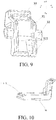
- FIG. 7 and FIG. 8 are schematic diagrams of an ink cartridge holder 3 according to a third specific implementation of the present invention.
- X-axis, Y-axis, and Z-axis directions of the ink cartridge are also X-axis, Y-axis, and Z-axis directions of the ink cartridge holder 3.
- the ink cartridge holder 3 is disposed in a printer.
- six grooves for placing the ink cartridge are disposed on the ink cartridge holder 3. After the ink cartridge is installed onto the grooves on the ink cartridge holder 3, a firmly fixed printing apparatus is formed.
- the ink cartridge holder 3 includes at least a lever body 31, a rotating shaft 32, and a lever opening 33.
- the lever body 31 may be rotated around the rotating shaft 32, and the lever opening 33 is used to cooperate with the engagement portion 122 of the ink cartridge to fix a side of the ink cartridge. Further, the lever body 31 rotates to drive the lever opening 33 to rotate.
- the lever body 31 is rotatable. In this case, when the ink cartridge has a manufacturing error, the lever body 31 can achieve a buffer function and a self-regulating function in a process of installing the ink cartridge, to protect the ink cartridge. Further, in a specific installation process, the engagement portion 122 and the lever opening 33 are engaged with each other, and a sectional area of the engagement portion 122 is less than or equal to an opening size of the lever opening 33. It is understood by a person skilled in the art that, according to the fourth specific embodiment of the present invention, in a process of installing the ink cartridge, as shown in FIG. 8 , the ink cartridge holder is provided with a slot 34.
- the ink cartridge After the latching portion 15 is in contact with the slot 34 on the ink cartridge holder, the ink cartridge is placed at ease inside the ink cartridge holder 3.
- the second plane 1b is pressed, and the guiding surface 1242 in the guiding portion 124 of the ink cartridge starts guiding.
- the compression surface 1241 of the ink cartridge compresses the lever body 31, so that the lever body 31 rotates counterclockwise in the XZ plane.
- the lever body 31 drives the lever opening 33 to perform similar circular motion. Specifically, when the lever body 31 rotates, the lever opening 33 moves towards the +Z-axis and -X-axis directions, and approaches the engagement portion 122 during the movement.
- the lever opening 33 is snap-fitted on the engagement portion 122.
- the engagement portion 122 moves towards the -Z-axis and +X-axis directions at the same time.
- the lever opening 33 and the engagement portion 122 are located in a same horizontal plane, the lever opening 33 is also exactly snap-fitted on the engagement portion 122.
- the compression surface 1241 compresses the lever opening 33 to rotate around the rotating shaft 32, so that the lever opening 33 approaches the ink cartridge, to reduce the length of the engagement portion 122, and avoid fracture or breakage of the engagement portion 122 caused when the length of the engagement portion 122 is extremely long and an engagement force is applied to an edge of the engagement portion 122.
- the compression surface 1241 compresses the lever body 31 to rotate around the rotating shaft 32, so that the lever opening 33 moves towards the +Z-axis and -X-axis directions.
- the ink cartridge has no large-sized part in the +Z-axis and -X-axis directions. Therefore, only a relatively small force is required, so that the pressing force on the second plane 1b is relatively small, the deformation degree of the stylus is small, and the ink cartridge is installed more easily and conveniently.
- the ink cartridge in a process of taking out the ink cartridge in the prior art, the ink cartridge needs to first move towards the -Z-axis direction.
- the stylus and the chip 13 are easily damaged. Therefore, in the prior art, sufficient space needs to be reserved in the ink cartridge in the -Z-axis direction, to avoid damage to the stylus and the chip 13.
- excessive space allowance in the -Z-axis direction may result in the problem of ink leakage.
- the entire ink cartridge tends to move in the -Z-axis direction.
- the entire ink cartridge tends to move in the +Z-axis direction. That is, the movement direction is contrary to that of the ink cartridge in the prior art, so that the stylus and the chip can be prevented from being damaged, and the problem of ink leakage caused by the space allowance of the ink cartridge in the -Z-axis direction can be avoided while miniaturization of the ink cartridge and the printer using same is implemented.
- the latching portion 15 and the engagement portion 122 are respectively located on the fourth plane 1d and the third plane 1c of the housing, so that the ink supply port 111 and the chip 13 are better fixed while stable fixation of the ink cartridge is implemented.
- the latching portion 15 is located in a middle part of the fourth plane 1d of the ink cartridge in the Z-axis direction
- the engagement portion 122 is located in an upper part of the third plane 1c in the Z-axis direction.
- the ink cartridge does not tend to rotate due to a force provided by flowing air in the Y-axis direction, thereby preventing the ink cartridge from shaking around a center spin axis that is perpendicular to the YZ plane.
- a guiding rib 311 is disposed on the lever body 31, the guiding surface 1242 of the ink cartridge is attached to an inner surface of the guiding rib 311, and the compression surface 1241 of the ink cartridge is in contact with the lever body 31, and drives the lever body 31 to rotate around the rotating shaft 32.
- the guiding rib 311 is used for guiding. Further, the guiding surface 1242 moves in attachment to the inner surface of the guiding rib 311.
- a guiding process of the guiding surface 1242 and the guiding rib 311 is earlier than engagement of the engagement portion 122 to the lever opening 33, so that the ink cartridge is guided before positioned, thereby implementing precise positioning of the ink cartridge and preventing installing the ink cartridge at an incorrect position.
- the compression surface 1241 of the ink cartridge is in contact with the lever body 31, and drives the lever body 31 to rotate around the rotating shaft 32.
- the rotating shaft 32 is located at a position adjacent to a middle part of the lever body 31 in Z-axis direction.
- the rotating shaft 32 and the lever body 31 are an integral structure, and the lever opening 33 is located above the lever body 31 in the +Z-axis direction.
- the lever body 31 is further provided with guiding ribs 311. Two guiding ribs 311 are separately disposed on the lever body 31 in the -Z-axis and +Y-axis directions and in the -Z-axis and +Y-axis directions.
- the guiding ribs 311 protrude from the lever body 31, and a part of the lever body 31 located between the two guiding ribs forms an inner surface.
- the compression surface 141 is in contact with the inner surface of the lever body 31.
- the ink cartridge holder 3 further includes a slot 34, and the slot 34 and the latching portion 15 of the ink cartridge are engaged with each other.
- the slot 34 is a concave slot, and the shape of the latching portion 15 of the ink cartridge is appropriate to a hollow portion in a concave surface of the slot 34.
- a side of the ink cartridge having the latching portion 15 is fixed first, and the ink cartridge is fixed to the ink cartridge holder 3 by means of a connection between the engagement portion 122 and the lever opening 33.
- the latching portion 15 may be a cone, and the slot 34 is correspondingly set to a shape that is appropriate to the size and shape of the cone.
- the latching portion 15 may be a long-strip object.
- the slot 34 is correspondingly set to a shape that is appropriate to the size and shape of the long-strip object.
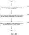
- FIG. 11 is a schematic flowchart of installing an ink cartridge according to a fourth specific implementation of the present invention. Specifically, the process is described with reference to FIG. 4 to FIG. 9 , and includes the following steps:
- step S101 is performed.
- the latching portion 15 of the ink cartridge is jointed into the slot 34 on the ink cartridge holder 3. It is understood by a person skilled in the art that, one end of the ink cartridge needs to be tightly fixed to the ink cartridge holder 3, and further, the ink cartridge is controlled by operating the other end of the ink cartridge.
- the latching portion 15 is disposed on the ink cartridge
- the corresponding slot 34 is disposed on the ink cartridge holder 3
- the latching portion 15 and the slot 34 should be located on a same horizontal line during the installation. Buckling of the latching portion 15 of the ink cartridge with the slot 34 on the ink cartridge holder should neither be excessively loose nor be excessively tight. Excessively loose jointing causes infirm fixation of the ink cartridge, and excessive tight jointing makes it difficult to take out the ink cartridge.
- step S102 is performed.
- the second plane 1b of the ink cartridge is pressed, and the ink cartridge gradually compresses the ink cartridge holder 3.
- the other end of the ink cartridge is not fixed.
- the stylus is disposed on at a lower end of the ink cartridge holder 3 on a side adjacent to the lever body 31. The stylus can cause the ink cartridge to be in an inclined state when the stylus is at ease. Further, under the action of an external force, the ink cartridge gradually compresses the ink cartridge holder.
- step S103 is performed.
- the lever opening 33 on the ink cartridge holder and the engagement portion 122 in the ink cartridge are engaged with each other.
- the lever opening 33 is disposed on the ink cartridge holder, and the engagement portion 122 is disposed on the ink cartridge.
- the ink cartridge gradually compresses the ink cartridge holder.
- the lever opening 33 and the engagement portion 122 are engaged with each other, and the ink cartridge is tightly fixed by means of a connection between left and right sides of the ink cartridge and the ink cartridge holder.
- the protective cover 16 is preferably removed from the ink cartridge, so that the protective cover is separated from the ink cartridge. Further, the ink cartridge is moved to the ink cartridge holder.
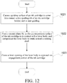
- FIG. 12 is a schematic flowchart of installing an ink cartridge having a guiding portion according to a preferred embodiment. It is understood by a person skilled in the art that FIG. 12 is a preferred implementation solution based on the fourth specific implementation of the present invention. Further, FIG. 12 is merely a schematic flowchart of mutual engagement of the guiding portion 124 and the lever body 31. In a specific process of installing the ink cartridge, it does not represent that the process includes only the steps in FIG. 11 . It is understood by a person skilled in the art that, in this embodiment, a whole installation process of the ink cartridge may be implemented with reference to the fourth specific implementation, and details are not described herein.
- step S1021 is performed.
- the guiding surface 1242 of the ink cartridge is in contact with the guiding rib 311 of the ink cartridge holder, and starts guiding.
- the guiding surface 1242 of the ink cartridge is attached to the inner surface of the guiding rib 311. This step is performed, and the guiding surface 1242 is attached to the guiding rib 311, to provide correct guiding and prevent installing the ink cartridge at an incorrect position.
- step S1022 is performed.
- the second plane 1b is pressed.
- the compression surface 1241 of the ink cartridge is in contact with the lever body 31, and compresses the lever body 31 to rotate around the rotating shaft 32.
- This step is performed to cause the lever body 31 to deflect by pressing the second plane 1b, and the lever opening 33 is further caused to move and approach the engagement portion 122.
- the rotating shaft 32 is fixed on the ink cartridge holder 3. Under the action of an external force, the ink cartridge compresses the lever body 31, and the lever body 31 rotates, and drives the lever opening 33 to deflect.
- step S1023 is performed.
- the lever opening 33 of the lever body approaches the engagement portion 122 of the ink cartridge. It is understood by a person skilled in the art that, in the process of installing the ink cartridge, the ink cartridge is horizontally placed inside the ink cartridge holder 3. The second plane 1b is pressed. The guiding portion 124 of the ink cartridge starts guiding. The compression surface 1241 of the ink cartridge compresses the lever body 31, so that the lever body 31 rotates counterclockwise in the XZ plane. During the rotation, the lever body 31 drives the lever opening 33 to perform similar circular motion. Specifically, when the lever body 31 rotates, the lever opening 33 moves towards the +Z-axis and -X-axis directions, and approaches the engagement portion 122 during the movement.
- the lever opening 33 is snap-fitted on the engagement portion 122.
- the engagement portion 122 moves towards the -Z-axis and +X-axis directions at the same time.
- the lever opening 33 and the engagement portion 122 are located on a same horizontal plane, the lever opening 33 is also exactly snap-fitted on the engagement portion 122.
- the operation portion 121 in a process of taking out the ink cartridge, the operation portion 121 is pushed first, so that the operation portion 121 moves in the +Z-axis and -X-axis directions.
- the engagement portion 122 also moves towards the +Z-axis and -X-axis directions.
- a direction of a force applied by the compression surface 1241 to the lever body 31 is exactly contrary to that of a force applied during installation. Therefore, the lever body 31 rotates clockwise in the XZ plane.
Landscapes
- Ink Jet (AREA)
Applications Claiming Priority (2)
| Application Number | Priority Date | Filing Date | Title |
|---|---|---|---|
| CN201510524601.7A CN106476439B (zh) | 2015-08-24 | 2015-08-24 | 一种墨盒及其安装方法 |
| PCT/CN2016/095774 WO2017032259A1 (fr) | 2015-08-24 | 2016-08-17 | Cartouche d'encre et son procédé d'installation |
Publications (3)
| Publication Number | Publication Date |
|---|---|
| EP3305530A1 true EP3305530A1 (fr) | 2018-04-11 |
| EP3305530A4 EP3305530A4 (fr) | 2018-05-30 |
| EP3305530B1 EP3305530B1 (fr) | 2020-02-26 |
Family
ID=58099605
Family Applications (1)
| Application Number | Title | Priority Date | Filing Date |
|---|---|---|---|
| EP16838518.5A Active EP3305530B1 (fr) | 2015-08-24 | 2016-08-17 | Cartouche d'encre connectée à un support de cartouche d'encre |
Country Status (4)
| Country | Link |
|---|---|
| EP (1) | EP3305530B1 (fr) |
| JP (2) | JP6613362B2 (fr) |
| CN (1) | CN106476439B (fr) |
| WO (1) | WO2017032259A1 (fr) |
Cited By (1)
| Publication number | Priority date | Publication date | Assignee | Title |
|---|---|---|---|---|
| FR3123018A1 (fr) * | 2021-05-20 | 2022-11-25 | Prolaser | Dispositif de protection pour une cartouche d’encre |
Families Citing this family (3)
| Publication number | Priority date | Publication date | Assignee | Title |
|---|---|---|---|---|
| CN106926586B (zh) * | 2017-03-29 | 2019-02-22 | 珠海纳思达企业管理有限公司 | 墨盒及墨盒的安装方法 |
| CN107546211B (zh) * | 2017-09-28 | 2024-07-09 | 珠海天威飞马打印耗材有限公司 | 芯片组件、激光打印机、粉盒组件及其控制方法 |
| CN220576879U (zh) * | 2022-10-28 | 2024-03-12 | 珠海纳思达企业管理有限公司 | 芯片及墨盒 |
Family Cites Families (26)
| Publication number | Priority date | Publication date | Assignee | Title |
|---|---|---|---|---|
| US6155678A (en) * | 1999-10-06 | 2000-12-05 | Lexmark International, Inc. | Replaceable ink cartridge for ink jet pen |
| TW541247B (en) * | 2000-01-31 | 2003-07-11 | Hewlett Packard Co | Latch and handle arrangement for a replaceable ink container |
| JP2001353878A (ja) * | 2000-06-13 | 2001-12-25 | Canon Inc | 吐出用液体収納容器および液体吐出記録装置 |
| US6666542B2 (en) * | 2001-03-30 | 2003-12-23 | Brother Kogyo Kabushiki Kaisha | Ink cartridge for printer or the like and ink cartridge positioning and locking mechanism |
| JP4058436B2 (ja) * | 2003-12-26 | 2008-03-12 | キヤノン株式会社 | インク収納容器 |
| JP2006116786A (ja) * | 2004-10-20 | 2006-05-11 | Canon Inc | 液体収納容器および該容器用ホルダ |
| CN100404268C (zh) * | 2004-10-20 | 2008-07-23 | 佳能株式会社 | 液体容器以及供墨系统 |
| US20080165214A1 (en) * | 2007-01-05 | 2008-07-10 | Kenneth Yuen | Ink cartridge fluid flow arrangements and methods |
| CN201009523Y (zh) * | 2007-02-28 | 2008-01-23 | 孙荣华 | 墨盒杠杆式伸缩定位装置 |
| CN201026707Y (zh) * | 2007-05-14 | 2008-02-27 | 孙荣华 | 杠杆式墨盒开启装置 |
| ATE499215T1 (de) * | 2008-03-31 | 2011-03-15 | Canon Kk | Tintenbehälter und tintenstrahlaufzeichnungssystem |
| DE202008018375U1 (de) * | 2008-11-18 | 2013-06-04 | Artech Gmbh Design + Production In Plastic | Vorrichtung zum Einbau in einen Drucker |
| CN101462410B (zh) * | 2008-12-31 | 2011-11-02 | 珠海纳思达电子科技有限公司 | 一种用于喷墨打印机的墨盒 |
| US8220902B2 (en) * | 2009-11-18 | 2012-07-17 | Eastman Kodak Company | Printhead with improved ink tank mounting reliability |
| CN101890841A (zh) * | 2010-07-02 | 2010-11-24 | 珠海纳思达企业管理有限公司 | 一种向喷墨打印机用墨盒内注入墨水的方法 |
| JP2012051315A (ja) * | 2010-09-03 | 2012-03-15 | Seiko Epson Corp | ホルダー、ホルダーに着脱可能な液体収容容器、及び、液体噴射装置 |
| JP5720148B2 (ja) * | 2010-09-03 | 2015-05-20 | セイコーエプソン株式会社 | 印刷材カートリッジ、及び、印刷材供給システム |
| CA2860539C (fr) * | 2012-01-12 | 2017-03-28 | Seiko Epson Corporation | Systeme d'alimentation pour cartouche et materiau d'impression |
| CN203093328U (zh) * | 2013-02-06 | 2013-07-31 | 珠海纳思达企业管理有限公司 | 墨盒 |
| US10124595B2 (en) * | 2013-09-30 | 2018-11-13 | Hewlett-Packard Development Company, L.P. | Ink cartridge |
| JP2015080875A (ja) * | 2013-10-22 | 2015-04-27 | セイコーエプソン株式会社 | 液体収容容器、キャップ |
| CN203864179U (zh) * | 2014-05-20 | 2014-10-08 | 珠海纳思达企业管理有限公司 | 一种墨盒 |
| JP5858125B2 (ja) * | 2014-11-10 | 2016-02-10 | セイコーエプソン株式会社 | 印刷材カートリッジ、及び、アダプター |
| CN204622833U (zh) * | 2015-04-22 | 2015-09-09 | 珠海纳思达企业管理有限公司 | 一种墨盒及包含该墨盒的喷墨打印机 |
| CN205044309U (zh) * | 2015-08-24 | 2016-02-24 | 珠海纳思达企业管理有限公司 | 紧固定墨盒以及与墨盒保持部连接的墨盒 |
| CN204955732U (zh) * | 2015-08-24 | 2016-01-13 | 珠海纳思达企业管理有限公司 | 一种墨盒 |
-
2015
- 2015-08-24 CN CN201510524601.7A patent/CN106476439B/zh active Active
-
2016
- 2016-08-17 EP EP16838518.5A patent/EP3305530B1/fr active Active
- 2016-08-17 WO PCT/CN2016/095774 patent/WO2017032259A1/fr not_active Ceased
- 2016-08-17 JP JP2018503599A patent/JP6613362B2/ja active Active
-
2019
- 2019-07-31 JP JP2019141578A patent/JP6768125B2/ja active Active
Cited By (1)
| Publication number | Priority date | Publication date | Assignee | Title |
|---|---|---|---|---|
| FR3123018A1 (fr) * | 2021-05-20 | 2022-11-25 | Prolaser | Dispositif de protection pour une cartouche d’encre |
Also Published As
| Publication number | Publication date |
|---|---|
| WO2017032259A1 (fr) | 2017-03-02 |
| JP6768125B2 (ja) | 2020-10-14 |
| JP6613362B2 (ja) | 2019-11-27 |
| EP3305530B1 (fr) | 2020-02-26 |
| JP2019206186A (ja) | 2019-12-05 |
| JP2018525246A (ja) | 2018-09-06 |
| CN106476439B (zh) | 2018-06-19 |
| EP3305530A4 (fr) | 2018-05-30 |
| CN106476439A (zh) | 2017-03-08 |
Similar Documents
| Publication | Publication Date | Title |
|---|---|---|
| EP3305530B1 (fr) | Cartouche d'encre connectée à un support de cartouche d'encre | |
| CN204955732U (zh) | 一种墨盒 | |
| CN216883642U (zh) | 芯片拆装夹具及活动芯片架 | |
| EP3549727A1 (fr) | Rasoir jumelé à double arête | |
| JP2012051316A5 (ja) | 液体収容容器を着脱可能なホルダー、これを備えた液体噴射装置、及び、液体収容容器 | |
| US10300593B2 (en) | Paint brush and a clamping and locating device used in the same | |
| CN205044309U (zh) | 紧固定墨盒以及与墨盒保持部连接的墨盒 | |
| CN106476438B (zh) | 一种反式连接的墨盒及其安装和拆卸的方法 | |
| CN223114562U (zh) | 芯片拆卸夹具及拆卸组件 | |
| CN214099159U (zh) | 一种光盘笼的旋转提手及光盘笼 | |
| CN215041414U (zh) | 成像盒 | |
| CN209948175U (zh) | 一种网线面板 | |
| KR200384191Y1 (ko) | 립스틱 조립체 | |
| CN210895694U (zh) | 顶出装置和打票机 | |
| CN205044311U (zh) | 一种止动式墨盒 | |
| CN209681231U (zh) | 一种可便捷更换碳刷的手电钻 | |
| CN108903772B (zh) | 盖体组件及具有其的吸尘器 | |
| EP3037275A1 (fr) | Piste de stylo | |
| CN201784255U (zh) | 一种墨盒开孔工具 | |
| EP4674637A1 (fr) | Taille-crayon | |
| CN209968287U (zh) | 一种易定位手持搅拌机连接头 | |
| CN220031524U (zh) | 一种墨盒和包装组件 | |
| CN208861413U (zh) | Pos机 | |
| CN209616655U (zh) | 一种打标机用尖针涂油装置 | |
| CN219028923U (zh) | 一种墨盒组件及墨盒包 |
Legal Events
| Date | Code | Title | Description |
|---|---|---|---|
| STAA | Information on the status of an ep patent application or granted ep patent |
Free format text: STATUS: THE INTERNATIONAL PUBLICATION HAS BEEN MADE |
|
| PUAI | Public reference made under article 153(3) epc to a published international application that has entered the european phase |
Free format text: ORIGINAL CODE: 0009012 |
|
| STAA | Information on the status of an ep patent application or granted ep patent |
Free format text: STATUS: REQUEST FOR EXAMINATION WAS MADE |
|
| 17P | Request for examination filed |
Effective date: 20180102 |
|
| AK | Designated contracting states |
Kind code of ref document: A1 Designated state(s): AL AT BE BG CH CY CZ DE DK EE ES FI FR GB GR HR HU IE IS IT LI LT LU LV MC MK MT NL NO PL PT RO RS SE SI SK SM TR |
|
| AX | Request for extension of the european patent |
Extension state: BA ME |
|
| A4 | Supplementary search report drawn up and despatched |
Effective date: 20180430 |
|
| RIC1 | Information provided on ipc code assigned before grant |
Ipc: B41J 2/175 20060101AFI20180423BHEP |
|
| DAV | Request for validation of the european patent (deleted) | ||
| DAX | Request for extension of the european patent (deleted) | ||
| STAA | Information on the status of an ep patent application or granted ep patent |
Free format text: STATUS: EXAMINATION IS IN PROGRESS |
|
| 17Q | First examination report despatched |
Effective date: 20181219 |
|
| GRAP | Despatch of communication of intention to grant a patent |
Free format text: ORIGINAL CODE: EPIDOSNIGR1 |
|
| STAA | Information on the status of an ep patent application or granted ep patent |
Free format text: STATUS: GRANT OF PATENT IS INTENDED |
|
| INTG | Intention to grant announced |
Effective date: 20191216 |
|
| GRAS | Grant fee paid |
Free format text: ORIGINAL CODE: EPIDOSNIGR3 |
|
| GRAA | (expected) grant |
Free format text: ORIGINAL CODE: 0009210 |
|
| STAA | Information on the status of an ep patent application or granted ep patent |
Free format text: STATUS: THE PATENT HAS BEEN GRANTED |
|
| AK | Designated contracting states |
Kind code of ref document: B1 Designated state(s): AL AT BE BG CH CY CZ DE DK EE ES FI FR GB GR HR HU IE IS IT LI LT LU LV MC MK MT NL NO PL PT RO RS SE SI SK SM TR |
|
| REG | Reference to a national code |
Ref country code: GB Ref legal event code: FG4D |
|
| REG | Reference to a national code |
Ref country code: CH Ref legal event code: EP |
|
| REG | Reference to a national code |
Ref country code: AT Ref legal event code: REF Ref document number: 1237156 Country of ref document: AT Kind code of ref document: T Effective date: 20200315 |
|
| REG | Reference to a national code |
Ref country code: IE Ref legal event code: FG4D |
|
| REG | Reference to a national code |
Ref country code: DE Ref legal event code: R096 Ref document number: 602016030795 Country of ref document: DE |
|
| REG | Reference to a national code |
Ref country code: NL Ref legal event code: FP |
|
| PG25 | Lapsed in a contracting state [announced via postgrant information from national office to epo] |
Ref country code: FI Free format text: LAPSE BECAUSE OF FAILURE TO SUBMIT A TRANSLATION OF THE DESCRIPTION OR TO PAY THE FEE WITHIN THE PRESCRIBED TIME-LIMIT Effective date: 20200226 Ref country code: NO Free format text: LAPSE BECAUSE OF FAILURE TO SUBMIT A TRANSLATION OF THE DESCRIPTION OR TO PAY THE FEE WITHIN THE PRESCRIBED TIME-LIMIT Effective date: 20200526 Ref country code: RS Free format text: LAPSE BECAUSE OF FAILURE TO SUBMIT A TRANSLATION OF THE DESCRIPTION OR TO PAY THE FEE WITHIN THE PRESCRIBED TIME-LIMIT Effective date: 20200226 |
|
| REG | Reference to a national code |
Ref country code: LT Ref legal event code: MG4D |
|
| PG25 | Lapsed in a contracting state [announced via postgrant information from national office to epo] |
Ref country code: IS Free format text: LAPSE BECAUSE OF FAILURE TO SUBMIT A TRANSLATION OF THE DESCRIPTION OR TO PAY THE FEE WITHIN THE PRESCRIBED TIME-LIMIT Effective date: 20200626 Ref country code: LV Free format text: LAPSE BECAUSE OF FAILURE TO SUBMIT A TRANSLATION OF THE DESCRIPTION OR TO PAY THE FEE WITHIN THE PRESCRIBED TIME-LIMIT Effective date: 20200226 Ref country code: SE Free format text: LAPSE BECAUSE OF FAILURE TO SUBMIT A TRANSLATION OF THE DESCRIPTION OR TO PAY THE FEE WITHIN THE PRESCRIBED TIME-LIMIT Effective date: 20200226 Ref country code: BG Free format text: LAPSE BECAUSE OF FAILURE TO SUBMIT A TRANSLATION OF THE DESCRIPTION OR TO PAY THE FEE WITHIN THE PRESCRIBED TIME-LIMIT Effective date: 20200526 Ref country code: GR Free format text: LAPSE BECAUSE OF FAILURE TO SUBMIT A TRANSLATION OF THE DESCRIPTION OR TO PAY THE FEE WITHIN THE PRESCRIBED TIME-LIMIT Effective date: 20200527 Ref country code: HR Free format text: LAPSE BECAUSE OF FAILURE TO SUBMIT A TRANSLATION OF THE DESCRIPTION OR TO PAY THE FEE WITHIN THE PRESCRIBED TIME-LIMIT Effective date: 20200226 |
|
| PG25 | Lapsed in a contracting state [announced via postgrant information from national office to epo] |
Ref country code: SK Free format text: LAPSE BECAUSE OF FAILURE TO SUBMIT A TRANSLATION OF THE DESCRIPTION OR TO PAY THE FEE WITHIN THE PRESCRIBED TIME-LIMIT Effective date: 20200226 Ref country code: ES Free format text: LAPSE BECAUSE OF FAILURE TO SUBMIT A TRANSLATION OF THE DESCRIPTION OR TO PAY THE FEE WITHIN THE PRESCRIBED TIME-LIMIT Effective date: 20200226 Ref country code: LT Free format text: LAPSE BECAUSE OF FAILURE TO SUBMIT A TRANSLATION OF THE DESCRIPTION OR TO PAY THE FEE WITHIN THE PRESCRIBED TIME-LIMIT Effective date: 20200226 Ref country code: PT Free format text: LAPSE BECAUSE OF FAILURE TO SUBMIT A TRANSLATION OF THE DESCRIPTION OR TO PAY THE FEE WITHIN THE PRESCRIBED TIME-LIMIT Effective date: 20200719 Ref country code: DK Free format text: LAPSE BECAUSE OF FAILURE TO SUBMIT A TRANSLATION OF THE DESCRIPTION OR TO PAY THE FEE WITHIN THE PRESCRIBED TIME-LIMIT Effective date: 20200226 Ref country code: SM Free format text: LAPSE BECAUSE OF FAILURE TO SUBMIT A TRANSLATION OF THE DESCRIPTION OR TO PAY THE FEE WITHIN THE PRESCRIBED TIME-LIMIT Effective date: 20200226 Ref country code: EE Free format text: LAPSE BECAUSE OF FAILURE TO SUBMIT A TRANSLATION OF THE DESCRIPTION OR TO PAY THE FEE WITHIN THE PRESCRIBED TIME-LIMIT Effective date: 20200226 Ref country code: RO Free format text: LAPSE BECAUSE OF FAILURE TO SUBMIT A TRANSLATION OF THE DESCRIPTION OR TO PAY THE FEE WITHIN THE PRESCRIBED TIME-LIMIT Effective date: 20200226 Ref country code: CZ Free format text: LAPSE BECAUSE OF FAILURE TO SUBMIT A TRANSLATION OF THE DESCRIPTION OR TO PAY THE FEE WITHIN THE PRESCRIBED TIME-LIMIT Effective date: 20200226 |
|
| REG | Reference to a national code |
Ref country code: AT Ref legal event code: MK05 Ref document number: 1237156 Country of ref document: AT Kind code of ref document: T Effective date: 20200226 |
|
| REG | Reference to a national code |
Ref country code: DE Ref legal event code: R097 Ref document number: 602016030795 Country of ref document: DE |
|
| PLBE | No opposition filed within time limit |
Free format text: ORIGINAL CODE: 0009261 |
|
| STAA | Information on the status of an ep patent application or granted ep patent |
Free format text: STATUS: NO OPPOSITION FILED WITHIN TIME LIMIT |
|
| PG25 | Lapsed in a contracting state [announced via postgrant information from national office to epo] |
Ref country code: AT Free format text: LAPSE BECAUSE OF FAILURE TO SUBMIT A TRANSLATION OF THE DESCRIPTION OR TO PAY THE FEE WITHIN THE PRESCRIBED TIME-LIMIT Effective date: 20200226 |
|
| 26N | No opposition filed |
Effective date: 20201127 |
|
| PG25 | Lapsed in a contracting state [announced via postgrant information from national office to epo] |
Ref country code: SI Free format text: LAPSE BECAUSE OF FAILURE TO SUBMIT A TRANSLATION OF THE DESCRIPTION OR TO PAY THE FEE WITHIN THE PRESCRIBED TIME-LIMIT Effective date: 20200226 Ref country code: PL Free format text: LAPSE BECAUSE OF FAILURE TO SUBMIT A TRANSLATION OF THE DESCRIPTION OR TO PAY THE FEE WITHIN THE PRESCRIBED TIME-LIMIT Effective date: 20200226 |
|
| PG25 | Lapsed in a contracting state [announced via postgrant information from national office to epo] |
Ref country code: MC Free format text: LAPSE BECAUSE OF FAILURE TO SUBMIT A TRANSLATION OF THE DESCRIPTION OR TO PAY THE FEE WITHIN THE PRESCRIBED TIME-LIMIT Effective date: 20200226 |
|
| REG | Reference to a national code |
Ref country code: CH Ref legal event code: PL |
|
| PG25 | Lapsed in a contracting state [announced via postgrant information from national office to epo] |
Ref country code: LU Free format text: LAPSE BECAUSE OF NON-PAYMENT OF DUE FEES Effective date: 20200817 Ref country code: LI Free format text: LAPSE BECAUSE OF NON-PAYMENT OF DUE FEES Effective date: 20200831 Ref country code: CH Free format text: LAPSE BECAUSE OF NON-PAYMENT OF DUE FEES Effective date: 20200831 |
|
| REG | Reference to a national code |
Ref country code: BE Ref legal event code: MM Effective date: 20200831 |
|
| PG25 | Lapsed in a contracting state [announced via postgrant information from national office to epo] |
Ref country code: BE Free format text: LAPSE BECAUSE OF NON-PAYMENT OF DUE FEES Effective date: 20200831 Ref country code: IE Free format text: LAPSE BECAUSE OF NON-PAYMENT OF DUE FEES Effective date: 20200817 |
|
| PG25 | Lapsed in a contracting state [announced via postgrant information from national office to epo] |
Ref country code: TR Free format text: LAPSE BECAUSE OF FAILURE TO SUBMIT A TRANSLATION OF THE DESCRIPTION OR TO PAY THE FEE WITHIN THE PRESCRIBED TIME-LIMIT Effective date: 20200226 Ref country code: MT Free format text: LAPSE BECAUSE OF FAILURE TO SUBMIT A TRANSLATION OF THE DESCRIPTION OR TO PAY THE FEE WITHIN THE PRESCRIBED TIME-LIMIT Effective date: 20200226 Ref country code: CY Free format text: LAPSE BECAUSE OF FAILURE TO SUBMIT A TRANSLATION OF THE DESCRIPTION OR TO PAY THE FEE WITHIN THE PRESCRIBED TIME-LIMIT Effective date: 20200226 |
|
| PG25 | Lapsed in a contracting state [announced via postgrant information from national office to epo] |
Ref country code: MK Free format text: LAPSE BECAUSE OF FAILURE TO SUBMIT A TRANSLATION OF THE DESCRIPTION OR TO PAY THE FEE WITHIN THE PRESCRIBED TIME-LIMIT Effective date: 20200226 Ref country code: AL Free format text: LAPSE BECAUSE OF FAILURE TO SUBMIT A TRANSLATION OF THE DESCRIPTION OR TO PAY THE FEE WITHIN THE PRESCRIBED TIME-LIMIT Effective date: 20200226 |
|
| REG | Reference to a national code |
Ref country code: DE Ref legal event code: R082 Ref document number: 602016030795 Country of ref document: DE Representative=s name: SUN, YIMING, M.SC. DIPL. SC. POL. UNIV., DE |
|
| PGFP | Annual fee paid to national office [announced via postgrant information from national office to epo] |
Ref country code: NL Payment date: 20250821 Year of fee payment: 10 |
|
| PGFP | Annual fee paid to national office [announced via postgrant information from national office to epo] |
Ref country code: DE Payment date: 20250820 Year of fee payment: 10 |
|
| PGFP | Annual fee paid to national office [announced via postgrant information from national office to epo] |
Ref country code: IT Payment date: 20250825 Year of fee payment: 10 |
|
| PGFP | Annual fee paid to national office [announced via postgrant information from national office to epo] |
Ref country code: GB Payment date: 20250821 Year of fee payment: 10 |
|
| PGFP | Annual fee paid to national office [announced via postgrant information from national office to epo] |
Ref country code: FR Payment date: 20250828 Year of fee payment: 10 |