EP3305555A1 - Pneumatique - Google Patents
Pneumatique Download PDFInfo
- Publication number
- EP3305555A1 EP3305555A1 EP17192174.5A EP17192174A EP3305555A1 EP 3305555 A1 EP3305555 A1 EP 3305555A1 EP 17192174 A EP17192174 A EP 17192174A EP 3305555 A1 EP3305555 A1 EP 3305555A1
- Authority
- EP
- European Patent Office
- Prior art keywords
- grooves
- oblique lateral
- tire
- lateral grooves
- terminating
- Prior art date
- Legal status (The legal status is an assumption and is not a legal conclusion. Google has not performed a legal analysis and makes no representation as to the accuracy of the status listed.)
- Granted
Links
Images


Classifications
-
- B—PERFORMING OPERATIONS; TRANSPORTING
- B60—VEHICLES IN GENERAL
- B60C—VEHICLE TYRES; TYRE INFLATION; TYRE CHANGING; CONNECTING VALVES TO INFLATABLE ELASTIC BODIES IN GENERAL; DEVICES OR ARRANGEMENTS RELATED TO TYRES
- B60C11/00—Tyre tread bands; Tread patterns; Anti-skid inserts
- B60C11/03—Tread patterns
- B60C11/12—Tread patterns characterised by the use of narrow slits or incisions, e.g. sipes
- B60C11/1204—Tread patterns characterised by the use of narrow slits or incisions, e.g. sipes with special shape of the sipe
- B60C11/1222—Twisted or warped shape in the sipe plane
-
- B—PERFORMING OPERATIONS; TRANSPORTING
- B60—VEHICLES IN GENERAL
- B60C—VEHICLE TYRES; TYRE INFLATION; TYRE CHANGING; CONNECTING VALVES TO INFLATABLE ELASTIC BODIES IN GENERAL; DEVICES OR ARRANGEMENTS RELATED TO TYRES
- B60C11/00—Tyre tread bands; Tread patterns; Anti-skid inserts
- B60C11/03—Tread patterns
- B60C11/0302—Tread patterns directional pattern, i.e. with main rolling direction
-
- B—PERFORMING OPERATIONS; TRANSPORTING
- B60—VEHICLES IN GENERAL
- B60C—VEHICLE TYRES; TYRE INFLATION; TYRE CHANGING; CONNECTING VALVES TO INFLATABLE ELASTIC BODIES IN GENERAL; DEVICES OR ARRANGEMENTS RELATED TO TYRES
- B60C11/00—Tyre tread bands; Tread patterns; Anti-skid inserts
- B60C11/03—Tread patterns
- B60C11/12—Tread patterns characterised by the use of narrow slits or incisions, e.g. sipes
- B60C11/1204—Tread patterns characterised by the use of narrow slits or incisions, e.g. sipes with special shape of the sipe
-
- B—PERFORMING OPERATIONS; TRANSPORTING
- B60—VEHICLES IN GENERAL
- B60C—VEHICLE TYRES; TYRE INFLATION; TYRE CHANGING; CONNECTING VALVES TO INFLATABLE ELASTIC BODIES IN GENERAL; DEVICES OR ARRANGEMENTS RELATED TO TYRES
- B60C11/00—Tyre tread bands; Tread patterns; Anti-skid inserts
- B60C11/03—Tread patterns
- B60C11/12—Tread patterns characterised by the use of narrow slits or incisions, e.g. sipes
- B60C11/1236—Tread patterns characterised by the use of narrow slits or incisions, e.g. sipes with special arrangements in the tread pattern
-
- B—PERFORMING OPERATIONS; TRANSPORTING
- B60—VEHICLES IN GENERAL
- B60C—VEHICLE TYRES; TYRE INFLATION; TYRE CHANGING; CONNECTING VALVES TO INFLATABLE ELASTIC BODIES IN GENERAL; DEVICES OR ARRANGEMENTS RELATED TO TYRES
- B60C11/00—Tyre tread bands; Tread patterns; Anti-skid inserts
- B60C11/03—Tread patterns
- B60C2011/0337—Tread patterns characterised by particular design features of the pattern
- B60C2011/0339—Grooves
- B60C2011/0374—Slant grooves, i.e. having an angle of about 5 to 35 degrees to the equatorial plane
-
- B—PERFORMING OPERATIONS; TRANSPORTING
- B60—VEHICLES IN GENERAL
- B60C—VEHICLE TYRES; TYRE INFLATION; TYRE CHANGING; CONNECTING VALVES TO INFLATABLE ELASTIC BODIES IN GENERAL; DEVICES OR ARRANGEMENTS RELATED TO TYRES
- B60C11/00—Tyre tread bands; Tread patterns; Anti-skid inserts
- B60C11/03—Tread patterns
- B60C2011/0337—Tread patterns characterised by particular design features of the pattern
- B60C2011/0339—Grooves
- B60C2011/0381—Blind or isolated grooves
-
- B—PERFORMING OPERATIONS; TRANSPORTING
- B60—VEHICLES IN GENERAL
- B60C—VEHICLE TYRES; TYRE INFLATION; TYRE CHANGING; CONNECTING VALVES TO INFLATABLE ELASTIC BODIES IN GENERAL; DEVICES OR ARRANGEMENTS RELATED TO TYRES
- B60C11/00—Tyre tread bands; Tread patterns; Anti-skid inserts
- B60C11/03—Tread patterns
- B60C11/12—Tread patterns characterised by the use of narrow slits or incisions, e.g. sipes
- B60C11/1204—Tread patterns characterised by the use of narrow slits or incisions, e.g. sipes with special shape of the sipe
- B60C2011/1213—Tread patterns characterised by the use of narrow slits or incisions, e.g. sipes with special shape of the sipe sinusoidal or zigzag at the tread surface
-
- B—PERFORMING OPERATIONS; TRANSPORTING
- B60—VEHICLES IN GENERAL
- B60C—VEHICLE TYRES; TYRE INFLATION; TYRE CHANGING; CONNECTING VALVES TO INFLATABLE ELASTIC BODIES IN GENERAL; DEVICES OR ARRANGEMENTS RELATED TO TYRES
- B60C11/00—Tyre tread bands; Tread patterns; Anti-skid inserts
- B60C11/03—Tread patterns
- B60C11/12—Tread patterns characterised by the use of narrow slits or incisions, e.g. sipes
- B60C11/1236—Tread patterns characterised by the use of narrow slits or incisions, e.g. sipes with special arrangements in the tread pattern
- B60C2011/1245—Tread patterns characterised by the use of narrow slits or incisions, e.g. sipes with special arrangements in the tread pattern being arranged in crossing relation, e.g. sipe mesh
Definitions
- the present invention relates to a pneumatic tire which can be suitably used as an all season tire and can achieve steering stability both on a dry road surface and a snowy road surface at a high level.
- a block pattern in which a tread portion is divided into a plurality of blocks by circumferential grooves extending continuously in a tire circumferential direction and lateral grooves extending in a tire axial direction is widely used (for example, Japanese Unexamined Patent Application Publication No. 2006-298202 ).
- grip force in the tire circumferential direction is obtained by shearing snow blocks compressed in the lateral grooves, therefore, driving performance and braking performance on a snowy road are exerted.
- lateral grip force is obtained by shearing snow blocks compressed in the circumferential grooves, therefore, the steering stability (straight running stability and cornering performance) on a snowy road is exerted.
- the present invention was made in view of the above, and a primary object thereof is to provide a pneumatic tire capable of achieving steering stability both on a dry road surface and a snowy road surface at a high level.
- a pneumatic tire comprises a tread portion comprising a first tread pattern portion provided on a first side of a tire equator in a tire axial direction and a second tread pattern portion provided on a second side of the tire equator in the tire axial direction, the first tread pattern portion and the second tread pattern portion being arranged line symmetrically with each other with respect to the tire equator except they are misaligned with each other in a tire circumferential direction, each of the first and the second tread pattern portions comprising, a plurality of oblique lateral grooves extending axially inwardly from a part of the pneumatic tire located on an axially outer side of a ground contact edge and obliquely to one side with respect to the tire circumferential direction and terminating without intersecting the tire equator to form inner ends thereof in a vicinity of the tire equator, a plurality of inner joint grooves each connecting on a side of the tire equator between the oblique
- one of the inner joint grooves and one of the oblique lateral grooves intersect in a three-way junction shape, one of the inner terminating grooves and one of the oblique lateral grooves intersect in a three-way junction shape, and one of the outer terminating grooves extends on the extended line of one of the outer joint groove so that the one of the outer joint groove and the one of the oblique lateral grooves intersect in a crossroad shape.
- a length Lac of the line segment AC in the tire axial direction, a length Lce of the line segment CE in the tire axial direction, a length Leh of a line segment EH extending between the intersection points E and H, and a ground contact half width TW which is a length in the tire axial direction between the tire equator and one of the ground contact edges satisfy following expressions: Lce ⁇ Leh ⁇ Lac 0.23 ⁇ Tw ⁇ Lac ⁇ 0.29 ⁇ TW 0.14 ⁇ TW ⁇ Lce ⁇ 0.20 ⁇ TW 0.15 ⁇ TW ⁇ Leh ⁇ 0.21 ⁇ TW .
- the tread portion comprises a row of center blocks, the center blocks being surrounded by the oblique lateral grooves, the inner joint grooves, and the center joint grooves, rows of middle blocks, the middle blocks being surrounded by the oblique lateral grooves, the inner joint grooves, and the outer joint grooves, and rows of shoulder blocks, the shoulder blocks being surrounded by the oblique lateral grooves, the outer joint grooves, and the ground contact edges, the center blocks are provided with sipes extending substantially in the tire axial direction, the middle blocks are provided with sipes extending substantially parallel to the outer joint grooves, and the shoulder blocks are provided with sipes extending substantially perpendicularly to the outer joint grooves.
- the tread portion comprises a tread rubber having rubber hardness in a range of from 45 to 70 degrees and a land ratio in a range of from 60% to 80%.
- the "tread edges” are defined as axially outermost ground contacting positions when the tire is in contact with a ground by being loaded with a standard tire load after mounted on a standard rim and inflated to a standard pressure.
- the "standard rim” is a wheel rim specified for the concerned tire by a standard included in a standardization system on which the tire is based, for example, the "normal wheel rim” in JATMA, "Design Rim” in TRA, and “Measuring Rim” in ETRTO.
- the "standard pressure” is air pressure specified for the concerned tire by a standard included in a standardization system on which the tire is based, for example, the “maximum air pressure” in JATMA, maximum value listed in the “TIRE LOAD LIMITS AT VARIOUS COLD INFLATION PRESSURES" table in TRA, and “INFLATION PRESSURE” in ETRTO, however, in a case of a tire for passenger cars, it is 180 kPa.
- the "standard load” is a tire load specified for the concerned tire by a standard included in a standardization system on which the tire is based, for example, the "maximum load capacity" in JATMA, maximum value listed in “TIRE LOAD LIMITS AT VARIOUS COLD INFLATION PRESSURES" table in TRA, and "LOAD CAPACITY" in ETRTO.
- the "rubber hardness” is a type-A durometer hardness measured at a temperature of 23 degrees Celsius according to Japanese Industrial Standard JIS K6253.
- the "land ratio” means a ratio (S/Sa) of surface area (S) of an entire land region between the tread edges and a virtual surface area (Sa) obtained by filling all the grooves in the land region between the tread edges.
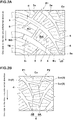
- a pneumatic tire 1 in this embodiment is an all season tire, and a tread portion 2 thereof does not have a circumferential groove extending continuously in a tire circumferential direction.
- the circumferential groove includes a straight groove and a zigzag groove.
- the tread portion 2 is provided with a first tread pattern portion P1 disposed on one side in a tire axial direction with respect to a tire equator (Co) and a second tread pattern portion P2 disposed on the other side in the tire axial direction with respect to the tire equator (Co).
- the first and second tread pattern portions P1 and P2 have line symmetrical patterns to each other except that the patterns are shifted from each other in the tire circumferential direction (that is, the phases are shifted in the tire circumferential direction).
- Each of the first and second tread pattern portions P1 and P2 are provided with a plurality of oblique lateral grooves 3 arranged at intervals in the tire circumferential direction, inner joint grooves 4 connecting between the oblique lateral grooves 3 adjacent in the tire circumferential direction on a side of the tire equator (Co), outer joint grooves 5 connecting between the oblique lateral grooves 3 adjacent in the tire circumferential direction on a side of a ground contact edge (TE), inner terminating grooves 7 each disposed between one of the inner joint grooves 4 and its adjacent one of the outer joint grooves 5, and outer terminating grooves 8 each disposed between one of the outer joint grooves 5 and the ground contact edge (TE).
- inner joint grooves 4 connecting between the oblique lateral grooves 3 adjacent in the tire circumferential direction on a side of the tire equator (Co)
- outer joint grooves 5 connecting between the oblique lateral grooves 3 adjacent in the tire circumferential direction on a side of a ground contact
- the tread portion 2 is provided with center joint grooves 6 extending across the tire equator (Co) to alternately connect the oblique lateral grooves 3 of the first tread pattern portion P1 and the oblique lateral grooves 3 of the second tread pattern portion P2.
- the tread portion 2 is divided into a row of center blocks (BC) which are surrounded by the oblique lateral grooves 3, the inner joint grooves 4, and the center joint grooves 6, a row of middle blocks (Bm) which are surrounded by the oblique lateral grooves 3, the inner joint grooves 4, and the outer joint grooves 5, and a row of shoulder blocks (Bs) which are surrounded by the oblique lateral grooves 3, the outer joint grooves 5, and the ground contact edges (TE).
- BC center blocks
- Bm middle blocks
- Bs shoulder blocks
- Fig. 2A representatively shows the first tread pattern portion P1.
- the oblique lateral grooves 3 extend axially inwardly and obliquely toward one side in the tire circumferential direction (toward a tire rolling direction in this embodiment) from a part of the pneumatic tire 1 located on an axially outer side of the ground contact edge TE to inner ends (3e) in the vicinity of the tire equator without crossing the tire equator (Co).
- the oblique lateral grooves 3 in this embodiment are formed as curved grooves in which the angles ⁇ thereof with respect to the tire axial direction gradually increase axially inwardly.
- the oblique lateral grooves 3 in this embodiment have groove widths w3 gradually decreasing axially inwardly.
- the "vicinity of the tire equator” means an area range in which a distance from the tire equator (Co) is not greater than 5 mm. Therefore, a distance (LO) between each of the inner ends (3e) and the tire equator (Co) is set to be not greater than 5 mm.
- each of the inner terminating grooves 7 extends from respective one of the oblique lateral grooves 3 between the inner joint groove 4 and its adjacent outer joint groove 5 toward an oblique lateral groove 3F adjacent thereto on the one side in the tire circumferential direction.
- the inner terminating grooves 7 terminate without intersecting with the respective adjacent oblique lateral grooves 3F.
- each of the outer terminating grooves 8 extends from respective one of the oblique lateral grooves 3 between the outer joint groove 5 and its adjacent ground contact edge (TE) toward the oblique lateral groove 3F adjacent thereto on the one side in the tire circumferential direction.
- the outer terminating grooves 8 also terminate without intersecting with the respective adjacent oblique lateral grooves 3F.
- the outer terminating grooves 8 extend on extended lines of the outer joint grooves 5, respectively. More precisely, the outer terminating groove 8 extends on the extended line of the outer joint groove 5R connecting between the oblique lateral groove 3 and its adjacent oblique lateral groove 3R on the other side in the tire circumferential direction. Thereby, the outer joint groove 5R and the outer terminating groove 8 form one groove, and this groove and the oblique lateral groove 3 intersect in a crossroad shape. Note that the inner joint groove 4 and the oblique lateral groove 3 intersect in a three-way junction shape, and the inner terminating groove 7 and the oblique lateral groove 3 intersect in a three-way junction shape.
- Each of the inner joint grooves 4, the outer joint grooves 5, the inner terminating grooves 7, and the outer terminating grooves 8 is inclined to a different direction from the oblique lateral grooves 3.
- an intersection angle between the inner joint groove 4 and the oblique lateral groove 3, an intersection angle between the outer joint groove 5 and the oblique lateral groove 3, an intersection angle between the inner terminating groove 7 and the oblique lateral groove 3, and an intersection angle between the outer terminating groove 8 and the oblique lateral groove 3 can each be brought closer to a right angle. This helps to increase block rigidity of the middle blocks (Bm) and the shoulder blocks (Bs).
- the center joint grooves 6 connect between the oblique lateral grooves 3 disposed in the first tread pattern portion P1 and the oblique lateral grooves 3 disposed in the second tread pattern portion P2 alternately in a zigzag manner.
- the center joint grooves 6 are disposed on an axially inner side of the inner joint grooves 4 and extend to cross the tire equator (Co).
- the oblique lateral grooves disposed in the first tread pattern portion P1 may be referred to as the oblique lateral grooves 31 and the oblique lateral grooves disposed in the second tread pattern portion P2 maybe referred to as the oblique lateral grooves 32.
- the center joint grooves 6 include first center joint grooves 6A and second center joint grooves 6B arranged alternately in the tire circumferential direction.
- the second center joint groove 6B connects between the oblique lateral groove 31 disposed in the first tread pattern portion P1 and the oblique lateral groove 32F disposed in the second tread pattern portion P2 so as to be misaligned to the one side in the tire circumferential direction with respect to the oblique lateral groove 31.
- the second center joint grooves 6B in this embodiment are inclined to a different direction from the oblique lateral grooves 31.
- first center joint groove 6A connects between the oblique lateral groove 31 disposed in the first tread pattern portion P1 and the oblique lateral groove 32R disposed in the second tread pattern portion P2 and misaligned to the other side in the tire circumferential direction with respect to the oblique lateral groove 31.
- the first center joint grooves 6A are inclined to the same direction as the oblique lateral grooves 31. That is, the first center joint grooves 6A and the second center joint grooves 6B are inclined to different directions from each other.
- the oblique lateral grooves 3, the inner and the outer joint grooves 4 and 5, and the inner and the outer terminating grooves 7 and 8 are inclined with respect to the tire axial direction, therefore, it is possible that snow blocks in the grooves 3, 4, 5, 7, and 8 exert snow shearing force both in the tire circumferential direction and in the tire axial direction. Therefore, it is possible that each snow block cooperate with each other to hold force received from a road surface during driving and braking and force received from a road surface during cornering. In addition, each force from a road surface exerts in a direction different from a width direction of each snow block, therefore, it is difficult for each snow block to break.
- the inner and the outer joint grooves 4 and 5 are inclined, therefore, it is possible to make intersection positions of the inner and the outer joint grooves 4 and 5 with the oblique lateral grooves 3 dispersed in the tire axial direction as compared with a case of a circumferential groove, and thereby, it is possible that the snow blocks in each of the grooves 3, 4, and 5 are combined to form firm joined bodies. Further, each of the joined bodies is combined by snow blocks in the center joint grooves 6 to form firmer joined bodies. Furthermore, by cooperation of these effects, it is possible that shearing force is increased as a whole of the snow blocks and that on-snow performance, on-snow steering stability in particular, is improved.
- the tread portion 2 is provided with no circumferential grooves, and the inner and the outer joint grooves 4 and 5 are inclined to different directions from the oblique lateral grooves 3.
- each of the middle blocks (Bm) and the shoulder blocks (Bs) is brought close to a rectangular shape, and that lateral rigidity of the blocks is secured at a high level.
- the steering stability on a dry road surface is improved by increasing cornering power against a dry road surface.
- angles of the inner joint grooves 4 with respect to the tire axial direction is set to be smaller than angles of the joint grooves 5 with respect to the tire axial direction in response to the angles ⁇ of the oblique lateral grooves 3 gradually increasing axially inwardly.
- angles of the center joint grooves 6 with respect to the tire axial direction are even smaller than the angles of the inner joint grooves 4 for the purpose of the steering stability on a dry road surface. Note that the angles of the center joint grooves 6 with respect to the tire axial direction may be zero degrees.
- one ends of the inner terminating grooves 7 terminate within the middle blocks (Bm) and one ends of the outer terminating grooves 8 terminate within the shoulder blocks (Bs).
- the on-snow steering stability is further improved while maintaining high block rigidity by the above-described rectangular shapes of each of the blocks (Bm) and (Bs).
- the steering stability on a dry road surface is improved by reducing number and lengths of the sipes, for example, as much as the improvement of the on-snow steering stability.
- angles of intersections between the inner joint grooves 4 and the oblique lateral grooves 3 and angles of intersections between the outer joint grooves 5 and the oblique lateral grooves 3 are in a range of 90 ⁇ 15 degrees.
- the tread portion 2 in this embodiment comprises a tread rubber having rubber hardness set to be in a range of from 45 to 70 degrees and a land ratio set to be in a range of from 60% to 80%.
- groove depths (Ha) (not shown) of the oblique lateral grooves 3 and the center joint grooves 6 are set to be in a range of from 8.1 to 9.1 mm
- groove depths (Hb) (not shown) of the inner and the outer joint grooves 4 and 5 and the inner and the outer terminating grooves 7 and 8 are set to be not greater than the groove depths (Ha).
- an angle ⁇ ac of a line segment (AC) extending between the intersection points A and C with respect to a tire axial direction line, an angle ⁇ ce of a line segment (CE) extending between the intersection points C and E with respect to the tire axial direction line and an angle ⁇ eg of a line segment (EG) extending between the intersection points E and G with respect to the tire axial direction line satisfy following expressions: ⁇ ac ⁇ ⁇ ce ⁇ ⁇ eg 15 degrees ⁇ ⁇ ac ⁇ 35 degrees 34 degrees ⁇ ⁇ ce ⁇ 54 degrees 47 degrees ⁇ ⁇ eg ⁇ 67 degrees .
- an arbitrary one of the oblique lateral grooves in the first tread pattern portion P1 is referred to as the oblique lateral groove 31, another one of the oblique lateral grooves adjacent to the oblique lateral groove 31 on the one side in the tire circumferential direction is referred to as the oblique lateral groove 31F, yet another one of the oblique lateral grooves 31 in the second tread pattern portion P2 which is misaligned to the one side in the tire circumferential direction is referred to as the oblique lateral groove 32F, yet another one of the oblique lateral grooves in the second tread pattern portion P2 which is misaligned to the other side in the tire circumferential direction is referred to as the oblique lateral groove 32R, and the intersection points A, C, E, G, and H will be described below based on the above.
- intersection points A, C, E, G, and H are defined as intersection points of groove width center lines of the respective grooves 31, 5, 6, and 32F.
- a length (Lac) of the line segment (AC) in the tire axial direction, a length (Lce) of the line segment (CE) in the tire axial direction, a length (Leh) of a line segment (EH) extending between the intersection points E and H, and a ground contact half width (TW) which is a length in the tire axial direction between the tire equator (Co) and one of the ground contact edges (TE) satisfy following expressions: Lce ⁇ Leh ⁇ Lac 0.23 ⁇ Tw ⁇ Lac ⁇ 0.29 ⁇ TW 0.14 ⁇ TW ⁇ Lce ⁇ 0.20 ⁇ TW 0.15 ⁇ TW ⁇ Leh ⁇ 0.21 ⁇ TW .
- the center blocks (BC) are provided with sipes 10c extending substantially in the tire axial direction.
- the middle blocks (Bm) are provided with sipes 10m extending substantially in parallel with the outer joint grooves 5.
- the shoulder blocks (Bs) are provided with sipes 10s extending substantially perpendicularly to the outer joint grooves 5.
- the sipes 10m of the middle blocks (Bm) extend substantially in parallel with the outer joint grooves 5, therefore, it is possible that the block rigidity is maintained at a higher level, which can contribute to the steering stability on a dry road surface.
- the sipes 10s of the shoulder blocks (Bs) extend substantially perpendicularly to the outer joint grooves 5, therefore, it is possible that more of longer sipes are formed and that driving performance and braking performance on a snowy road are improved.
- the sipes 10c of the center blocks (BC) extend substantially in the tire axial direction, therefore, the sipes 10c are formed to extend in different angles from those of the sipes 10m and 10s. Thereby, it is possible that edge effects on multiple directions are ensured and that the on-snow steering stability is improved.
- the sipes 10c extend substantially in the tire axial direction
- length directions of the sipes 10c and the tire axial direction are parallel or angles therebetween are not greater than 10 degrees.
- the sipes 10m extend substantially in parallel with the outer joint grooves 5" means that length directions of the sipes 10m are parallel to groove centers of the outer joint grooves 5, or angles therebetween are not greater than 10 degrees.
- the sipes 10s extend substantially perpendicularly to the outer joint grooves 5" means that angles between the length directions of the sipes 10m and the groove centers of the outer joint grooves 5 are in a range of from 80 to 100 degrees. Note that it is preferred that at least one end of each sipes 10c, 10m, and 10s terminates within the block for the steering stability on a dry road surface.
- Each of the test tires has substantially the same configuration except as shown in Table 1. Note that the common specifications are as follows. Land ratio: 70% Ground contacting width: 160 mm Hardness of tread rubber measured by a type-A durometer: 65 degrees Groove depth of each groove: 8.6 mm
- test tires were mounted on rims (16x6.5) of all wheels of a Volkswagen GOLF 7.0 (displacement of 2000 cc) under the conditions of tire pressure of 200 kPa (front wheels) and 200 kPa (rear wheels). Then, the steering stability during running on a test course covered with snow was evaluated by the driver's feeling by a ten point method, wherein the larger the numerical value, the better the steering stability.
- the tires as the examples can increase the potential of the total of the steering stability on a dry road surface and the on-snow steering stability and that both can be achieved at a high level.
Landscapes
- Engineering & Computer Science (AREA)
- Mechanical Engineering (AREA)
- Tires In General (AREA)
Applications Claiming Priority (1)
| Application Number | Priority Date | Filing Date | Title |
|---|---|---|---|
| JP2016193706A JP6737112B2 (ja) | 2016-09-30 | 2016-09-30 | 空気入りタイヤ |
Publications (2)
| Publication Number | Publication Date |
|---|---|
| EP3305555A1 true EP3305555A1 (fr) | 2018-04-11 |
| EP3305555B1 EP3305555B1 (fr) | 2020-02-26 |
Family
ID=59923338
Family Applications (1)
| Application Number | Title | Priority Date | Filing Date |
|---|---|---|---|
| EP17192174.5A Active EP3305555B1 (fr) | 2016-09-30 | 2017-09-20 | Pneumatique |
Country Status (4)
| Country | Link |
|---|---|
| US (1) | US11505005B2 (fr) |
| EP (1) | EP3305555B1 (fr) |
| JP (1) | JP6737112B2 (fr) |
| CN (1) | CN107878120B (fr) |
Cited By (3)
| Publication number | Priority date | Publication date | Assignee | Title |
|---|---|---|---|---|
| IT202100014642A1 (it) * | 2021-06-08 | 2022-12-08 | Pirelli | Pneumatico per ruote di veicoli per trasporto leggero |
| EP3960501A4 (fr) * | 2019-04-26 | 2023-01-18 | The Yokohama Rubber Co., Ltd. | Pneumatique |
| EP4484179A1 (fr) * | 2023-06-26 | 2025-01-01 | Sumitomo Rubber Industries, Ltd. | Pneumatique |
Families Citing this family (3)
| Publication number | Priority date | Publication date | Assignee | Title |
|---|---|---|---|---|
| JP2019066454A (ja) | 2017-09-29 | 2019-04-25 | ミネベアミツミ株式会社 | ひずみゲージ、センサモジュール |
| JP2019113411A (ja) * | 2017-12-22 | 2019-07-11 | ミネベアミツミ株式会社 | ひずみゲージ、センサモジュール |
| JP6658789B2 (ja) * | 2018-04-17 | 2020-03-04 | 横浜ゴム株式会社 | 空気入りタイヤ |
Citations (5)
| Publication number | Priority date | Publication date | Assignee | Title |
|---|---|---|---|---|
| EP0609195A1 (fr) * | 1993-01-28 | 1994-08-03 | Semperit Reifen Aktiengesellschaft | Bandage pneumatique pour véhicule |
| JPH06305307A (ja) * | 1993-04-23 | 1994-11-01 | Bridgestone Corp | 空気入り冬用タイヤ |
| JP2006298202A (ja) | 2005-04-21 | 2006-11-02 | Sumitomo Rubber Ind Ltd | 空気入りタイヤ |
| DE102011055916A1 (de) * | 2011-12-01 | 2013-06-06 | Continental Reifen Deutschland Gmbh | Fahrzeugluftreifen |
| WO2015108079A1 (fr) * | 2014-01-15 | 2015-07-23 | 株式会社ブリヂストン | Pneu |
Family Cites Families (20)
| Publication number | Priority date | Publication date | Assignee | Title |
|---|---|---|---|---|
| DE3913199A1 (de) * | 1989-04-21 | 1990-10-25 | Sp Reifenwerke Gmbh | Laufflaechenprofilierung bei fahrzeugreifen |
| JP3351894B2 (ja) * | 1994-02-07 | 2002-12-03 | 株式会社ブリヂストン | 重荷重用空気入りタイヤ |
| ES2158050T3 (es) * | 1994-09-28 | 2001-09-01 | Bridgestone Corp | Cubiertas neumaticas robustas. |
| JPH08188014A (ja) * | 1995-01-11 | 1996-07-23 | Bridgestone Corp | 重荷重用空気入りタイヤ |
| EP1238827B1 (fr) * | 2001-03-06 | 2004-11-03 | Continental Aktiengesellschaft | Sculpture de bande de roulement |
| DE60232920D1 (de) * | 2002-12-19 | 2009-08-20 | Pirelli | Profilmuster für winterreifen |
| KR100784276B1 (ko) * | 2003-07-09 | 2007-12-12 | 한국타이어 주식회사 | 스터드레스 스노우 타이어 |
| KR20050038130A (ko) * | 2003-10-21 | 2005-04-27 | 한국타이어 주식회사 | 고성능 타이어의 트레드 패턴구조 |
| KR20060002544A (ko) * | 2004-07-02 | 2006-01-09 | 한국타이어 주식회사 | 스노우 성능이 향상된 고성능 사계절용 타이어의 트레드패턴구조 |
| JP4899787B2 (ja) * | 2006-10-26 | 2012-03-21 | 横浜ゴム株式会社 | 空気入りタイヤ |
| JP4329912B1 (ja) * | 2009-03-16 | 2009-09-09 | 横浜ゴム株式会社 | 空気入りタイヤ |
| EP2748017B1 (fr) * | 2011-09-21 | 2018-03-07 | Pirelli Tyre S.p.A. | Pneumatique |
| JP5620940B2 (ja) * | 2012-04-17 | 2014-11-05 | 住友ゴム工業株式会社 | 空気入りタイヤ |
| JP5986542B2 (ja) * | 2013-07-12 | 2016-09-06 | 住友ゴム工業株式会社 | 空気入りタイヤ |
| JP6248537B2 (ja) * | 2013-10-24 | 2017-12-20 | 横浜ゴム株式会社 | 空気入りタイヤ |
| JP5932761B2 (ja) * | 2013-12-18 | 2016-06-08 | 住友ゴム工業株式会社 | 空気入りタイヤ |
| CN105873775B (zh) * | 2013-12-23 | 2018-09-04 | 倍耐力轮胎股份公司 | 用于车辆车轮的具有改进的胎面花纹的轮胎 |
| JP5981949B2 (ja) * | 2014-02-18 | 2016-08-31 | 住友ゴム工業株式会社 | 空気入りタイヤ |
| JP6362910B2 (ja) * | 2014-04-11 | 2018-07-25 | 株式会社ブリヂストン | 空気入りタイヤ |
| JP1575432S (fr) * | 2016-09-14 | 2018-04-16 |
-
2016
- 2016-09-30 JP JP2016193706A patent/JP6737112B2/ja not_active Expired - Fee Related
-
2017
- 2017-09-20 EP EP17192174.5A patent/EP3305555B1/fr active Active
- 2017-09-21 CN CN201710858954.XA patent/CN107878120B/zh not_active Expired - Fee Related
- 2017-09-28 US US15/719,009 patent/US11505005B2/en active Active
Patent Citations (5)
| Publication number | Priority date | Publication date | Assignee | Title |
|---|---|---|---|---|
| EP0609195A1 (fr) * | 1993-01-28 | 1994-08-03 | Semperit Reifen Aktiengesellschaft | Bandage pneumatique pour véhicule |
| JPH06305307A (ja) * | 1993-04-23 | 1994-11-01 | Bridgestone Corp | 空気入り冬用タイヤ |
| JP2006298202A (ja) | 2005-04-21 | 2006-11-02 | Sumitomo Rubber Ind Ltd | 空気入りタイヤ |
| DE102011055916A1 (de) * | 2011-12-01 | 2013-06-06 | Continental Reifen Deutschland Gmbh | Fahrzeugluftreifen |
| WO2015108079A1 (fr) * | 2014-01-15 | 2015-07-23 | 株式会社ブリヂストン | Pneu |
Cited By (6)
| Publication number | Priority date | Publication date | Assignee | Title |
|---|---|---|---|---|
| EP3960501A4 (fr) * | 2019-04-26 | 2023-01-18 | The Yokohama Rubber Co., Ltd. | Pneumatique |
| US12319093B2 (en) | 2019-04-26 | 2025-06-03 | The Yokohama Rubber Co., Ltd. | Pneumatic tire |
| IT202100014642A1 (it) * | 2021-06-08 | 2022-12-08 | Pirelli | Pneumatico per ruote di veicoli per trasporto leggero |
| WO2022259085A1 (fr) * | 2021-06-08 | 2022-12-15 | Pirelli Tyre S.P.A. | Pneumatique pour roues de véhicules utilitaires |
| US12545054B2 (en) | 2021-06-08 | 2026-02-10 | Pirelli Tyre S.P.A. | Tyre for commercial vehicle wheels |
| EP4484179A1 (fr) * | 2023-06-26 | 2025-01-01 | Sumitomo Rubber Industries, Ltd. | Pneumatique |
Also Published As
| Publication number | Publication date |
|---|---|
| JP2018052422A (ja) | 2018-04-05 |
| EP3305555B1 (fr) | 2020-02-26 |
| JP6737112B2 (ja) | 2020-08-05 |
| US11505005B2 (en) | 2022-11-22 |
| CN107878120B (zh) | 2021-03-12 |
| US20180093534A1 (en) | 2018-04-05 |
| CN107878120A (zh) | 2018-04-06 |
Similar Documents
| Publication | Publication Date | Title |
|---|---|---|
| EP3189983B1 (fr) | Pneumatique | |
| US10994575B2 (en) | Tire | |
| US9994077B2 (en) | Pneumatic tire | |
| US10894446B2 (en) | Tire | |
| EP3305555B1 (fr) | Pneumatique | |
| EP3392064B1 (fr) | Pneumatique | |
| US11192404B2 (en) | Tyre | |
| US11155121B2 (en) | Tire | |
| EP3042792B1 (fr) | Pneumatique | |
| EP3315326B1 (fr) | Pneumatique | |
| EP3231639A1 (fr) | Pneumatique | |
| US10611191B2 (en) | Tire | |
| US11046117B2 (en) | Tire | |
| EP3409507B1 (fr) | Pneumatique | |
| EP3260307A1 (fr) | Pneumatique | |
| US11142026B2 (en) | Tyre | |
| US11179973B2 (en) | Tire | |
| EP3970996B1 (fr) | Pneumatique |
Legal Events
| Date | Code | Title | Description |
|---|---|---|---|
| PUAI | Public reference made under article 153(3) epc to a published international application that has entered the european phase |
Free format text: ORIGINAL CODE: 0009012 |
|
| STAA | Information on the status of an ep patent application or granted ep patent |
Free format text: STATUS: THE APPLICATION HAS BEEN PUBLISHED |
|
| AK | Designated contracting states |
Kind code of ref document: A1 Designated state(s): AL AT BE BG CH CY CZ DE DK EE ES FI FR GB GR HR HU IE IS IT LI LT LU LV MC MK MT NL NO PL PT RO RS SE SI SK SM TR |
|
| AX | Request for extension of the european patent |
Extension state: BA ME |
|
| STAA | Information on the status of an ep patent application or granted ep patent |
Free format text: STATUS: REQUEST FOR EXAMINATION WAS MADE |
|
| 17P | Request for examination filed |
Effective date: 20180813 |
|
| RBV | Designated contracting states (corrected) |
Designated state(s): AL AT BE BG CH CY CZ DE DK EE ES FI FR GB GR HR HU IE IS IT LI LT LU LV MC MK MT NL NO PL PT RO RS SE SI SK SM TR |
|
| RIC1 | Information provided on ipc code assigned before grant |
Ipc: B60C 11/03 20060101AFI20190905BHEP |
|
| GRAP | Despatch of communication of intention to grant a patent |
Free format text: ORIGINAL CODE: EPIDOSNIGR1 |
|
| STAA | Information on the status of an ep patent application or granted ep patent |
Free format text: STATUS: GRANT OF PATENT IS INTENDED |
|
| INTG | Intention to grant announced |
Effective date: 20191011 |
|
| GRAS | Grant fee paid |
Free format text: ORIGINAL CODE: EPIDOSNIGR3 |
|
| GRAA | (expected) grant |
Free format text: ORIGINAL CODE: 0009210 |
|
| STAA | Information on the status of an ep patent application or granted ep patent |
Free format text: STATUS: THE PATENT HAS BEEN GRANTED |
|
| AK | Designated contracting states |
Kind code of ref document: B1 Designated state(s): AL AT BE BG CH CY CZ DE DK EE ES FI FR GB GR HR HU IE IS IT LI LT LU LV MC MK MT NL NO PL PT RO RS SE SI SK SM TR |
|
| REG | Reference to a national code |
Ref country code: GB Ref legal event code: FG4D |
|
| REG | Reference to a national code |
Ref country code: CH Ref legal event code: EP |
|
| REG | Reference to a national code |
Ref country code: DE Ref legal event code: R096 Ref document number: 602017012187 Country of ref document: DE |
|
| REG | Reference to a national code |
Ref country code: AT Ref legal event code: REF Ref document number: 1237178 Country of ref document: AT Kind code of ref document: T Effective date: 20200315 |
|
| REG | Reference to a national code |
Ref country code: IE Ref legal event code: FG4D |
|
| PG25 | Lapsed in a contracting state [announced via postgrant information from national office to epo] |
Ref country code: RS Free format text: LAPSE BECAUSE OF FAILURE TO SUBMIT A TRANSLATION OF THE DESCRIPTION OR TO PAY THE FEE WITHIN THE PRESCRIBED TIME-LIMIT Effective date: 20200226 Ref country code: FI Free format text: LAPSE BECAUSE OF FAILURE TO SUBMIT A TRANSLATION OF THE DESCRIPTION OR TO PAY THE FEE WITHIN THE PRESCRIBED TIME-LIMIT Effective date: 20200226 Ref country code: NO Free format text: LAPSE BECAUSE OF FAILURE TO SUBMIT A TRANSLATION OF THE DESCRIPTION OR TO PAY THE FEE WITHIN THE PRESCRIBED TIME-LIMIT Effective date: 20200526 |
|
| REG | Reference to a national code |
Ref country code: NL Ref legal event code: MP Effective date: 20200226 |
|
| REG | Reference to a national code |
Ref country code: LT Ref legal event code: MG4D |
|
| PG25 | Lapsed in a contracting state [announced via postgrant information from national office to epo] |
Ref country code: LV Free format text: LAPSE BECAUSE OF FAILURE TO SUBMIT A TRANSLATION OF THE DESCRIPTION OR TO PAY THE FEE WITHIN THE PRESCRIBED TIME-LIMIT Effective date: 20200226 Ref country code: SE Free format text: LAPSE BECAUSE OF FAILURE TO SUBMIT A TRANSLATION OF THE DESCRIPTION OR TO PAY THE FEE WITHIN THE PRESCRIBED TIME-LIMIT Effective date: 20200226 Ref country code: HR Free format text: LAPSE BECAUSE OF FAILURE TO SUBMIT A TRANSLATION OF THE DESCRIPTION OR TO PAY THE FEE WITHIN THE PRESCRIBED TIME-LIMIT Effective date: 20200226 Ref country code: BG Free format text: LAPSE BECAUSE OF FAILURE TO SUBMIT A TRANSLATION OF THE DESCRIPTION OR TO PAY THE FEE WITHIN THE PRESCRIBED TIME-LIMIT Effective date: 20200526 Ref country code: IS Free format text: LAPSE BECAUSE OF FAILURE TO SUBMIT A TRANSLATION OF THE DESCRIPTION OR TO PAY THE FEE WITHIN THE PRESCRIBED TIME-LIMIT Effective date: 20200626 Ref country code: GR Free format text: LAPSE BECAUSE OF FAILURE TO SUBMIT A TRANSLATION OF THE DESCRIPTION OR TO PAY THE FEE WITHIN THE PRESCRIBED TIME-LIMIT Effective date: 20200527 |
|
| PG25 | Lapsed in a contracting state [announced via postgrant information from national office to epo] |
Ref country code: NL Free format text: LAPSE BECAUSE OF FAILURE TO SUBMIT A TRANSLATION OF THE DESCRIPTION OR TO PAY THE FEE WITHIN THE PRESCRIBED TIME-LIMIT Effective date: 20200226 |
|
| PG25 | Lapsed in a contracting state [announced via postgrant information from national office to epo] |
Ref country code: SK Free format text: LAPSE BECAUSE OF FAILURE TO SUBMIT A TRANSLATION OF THE DESCRIPTION OR TO PAY THE FEE WITHIN THE PRESCRIBED TIME-LIMIT Effective date: 20200226 Ref country code: RO Free format text: LAPSE BECAUSE OF FAILURE TO SUBMIT A TRANSLATION OF THE DESCRIPTION OR TO PAY THE FEE WITHIN THE PRESCRIBED TIME-LIMIT Effective date: 20200226 Ref country code: CZ Free format text: LAPSE BECAUSE OF FAILURE TO SUBMIT A TRANSLATION OF THE DESCRIPTION OR TO PAY THE FEE WITHIN THE PRESCRIBED TIME-LIMIT Effective date: 20200226 Ref country code: EE Free format text: LAPSE BECAUSE OF FAILURE TO SUBMIT A TRANSLATION OF THE DESCRIPTION OR TO PAY THE FEE WITHIN THE PRESCRIBED TIME-LIMIT Effective date: 20200226 Ref country code: SM Free format text: LAPSE BECAUSE OF FAILURE TO SUBMIT A TRANSLATION OF THE DESCRIPTION OR TO PAY THE FEE WITHIN THE PRESCRIBED TIME-LIMIT Effective date: 20200226 Ref country code: PT Free format text: LAPSE BECAUSE OF FAILURE TO SUBMIT A TRANSLATION OF THE DESCRIPTION OR TO PAY THE FEE WITHIN THE PRESCRIBED TIME-LIMIT Effective date: 20200719 Ref country code: DK Free format text: LAPSE BECAUSE OF FAILURE TO SUBMIT A TRANSLATION OF THE DESCRIPTION OR TO PAY THE FEE WITHIN THE PRESCRIBED TIME-LIMIT Effective date: 20200226 Ref country code: ES Free format text: LAPSE BECAUSE OF FAILURE TO SUBMIT A TRANSLATION OF THE DESCRIPTION OR TO PAY THE FEE WITHIN THE PRESCRIBED TIME-LIMIT Effective date: 20200226 Ref country code: LT Free format text: LAPSE BECAUSE OF FAILURE TO SUBMIT A TRANSLATION OF THE DESCRIPTION OR TO PAY THE FEE WITHIN THE PRESCRIBED TIME-LIMIT Effective date: 20200226 |
|
| REG | Reference to a national code |
Ref country code: AT Ref legal event code: MK05 Ref document number: 1237178 Country of ref document: AT Kind code of ref document: T Effective date: 20200226 |
|
| REG | Reference to a national code |
Ref country code: DE Ref legal event code: R097 Ref document number: 602017012187 Country of ref document: DE |
|
| PLBE | No opposition filed within time limit |
Free format text: ORIGINAL CODE: 0009261 |
|
| STAA | Information on the status of an ep patent application or granted ep patent |
Free format text: STATUS: NO OPPOSITION FILED WITHIN TIME LIMIT |
|
| PG25 | Lapsed in a contracting state [announced via postgrant information from national office to epo] |
Ref country code: AT Free format text: LAPSE BECAUSE OF FAILURE TO SUBMIT A TRANSLATION OF THE DESCRIPTION OR TO PAY THE FEE WITHIN THE PRESCRIBED TIME-LIMIT Effective date: 20200226 Ref country code: IT Free format text: LAPSE BECAUSE OF FAILURE TO SUBMIT A TRANSLATION OF THE DESCRIPTION OR TO PAY THE FEE WITHIN THE PRESCRIBED TIME-LIMIT Effective date: 20200226 |
|
| 26N | No opposition filed |
Effective date: 20201127 |
|
| PG25 | Lapsed in a contracting state [announced via postgrant information from national office to epo] |
Ref country code: PL Free format text: LAPSE BECAUSE OF FAILURE TO SUBMIT A TRANSLATION OF THE DESCRIPTION OR TO PAY THE FEE WITHIN THE PRESCRIBED TIME-LIMIT Effective date: 20200226 Ref country code: SI Free format text: LAPSE BECAUSE OF FAILURE TO SUBMIT A TRANSLATION OF THE DESCRIPTION OR TO PAY THE FEE WITHIN THE PRESCRIBED TIME-LIMIT Effective date: 20200226 |
|
| REG | Reference to a national code |
Ref country code: CH Ref legal event code: PL |
|
| REG | Reference to a national code |
Ref country code: BE Ref legal event code: MM Effective date: 20200930 |
|
| PG25 | Lapsed in a contracting state [announced via postgrant information from national office to epo] |
Ref country code: LU Free format text: LAPSE BECAUSE OF NON-PAYMENT OF DUE FEES Effective date: 20200920 |
|
| PG25 | Lapsed in a contracting state [announced via postgrant information from national office to epo] |
Ref country code: IE Free format text: LAPSE BECAUSE OF NON-PAYMENT OF DUE FEES Effective date: 20200920 Ref country code: LI Free format text: LAPSE BECAUSE OF NON-PAYMENT OF DUE FEES Effective date: 20200930 Ref country code: BE Free format text: LAPSE BECAUSE OF NON-PAYMENT OF DUE FEES Effective date: 20200930 Ref country code: CH Free format text: LAPSE BECAUSE OF NON-PAYMENT OF DUE FEES Effective date: 20200930 |
|
| GBPC | Gb: european patent ceased through non-payment of renewal fee |
Effective date: 20210920 |
|
| PG25 | Lapsed in a contracting state [announced via postgrant information from national office to epo] |
Ref country code: TR Free format text: LAPSE BECAUSE OF FAILURE TO SUBMIT A TRANSLATION OF THE DESCRIPTION OR TO PAY THE FEE WITHIN THE PRESCRIBED TIME-LIMIT Effective date: 20200226 Ref country code: MT Free format text: LAPSE BECAUSE OF FAILURE TO SUBMIT A TRANSLATION OF THE DESCRIPTION OR TO PAY THE FEE WITHIN THE PRESCRIBED TIME-LIMIT Effective date: 20200226 Ref country code: CY Free format text: LAPSE BECAUSE OF FAILURE TO SUBMIT A TRANSLATION OF THE DESCRIPTION OR TO PAY THE FEE WITHIN THE PRESCRIBED TIME-LIMIT Effective date: 20200226 |
|
| PG25 | Lapsed in a contracting state [announced via postgrant information from national office to epo] |
Ref country code: MK Free format text: LAPSE BECAUSE OF FAILURE TO SUBMIT A TRANSLATION OF THE DESCRIPTION OR TO PAY THE FEE WITHIN THE PRESCRIBED TIME-LIMIT Effective date: 20200226 Ref country code: MC Free format text: LAPSE BECAUSE OF FAILURE TO SUBMIT A TRANSLATION OF THE DESCRIPTION OR TO PAY THE FEE WITHIN THE PRESCRIBED TIME-LIMIT Effective date: 20200226 Ref country code: AL Free format text: LAPSE BECAUSE OF FAILURE TO SUBMIT A TRANSLATION OF THE DESCRIPTION OR TO PAY THE FEE WITHIN THE PRESCRIBED TIME-LIMIT Effective date: 20200226 |
|
| PG25 | Lapsed in a contracting state [announced via postgrant information from national office to epo] |
Ref country code: GB Free format text: LAPSE BECAUSE OF NON-PAYMENT OF DUE FEES Effective date: 20210920 |
|
| P01 | Opt-out of the competence of the unified patent court (upc) registered |
Effective date: 20230510 |
|
| PGFP | Annual fee paid to national office [announced via postgrant information from national office to epo] |
Ref country code: FR Payment date: 20230808 Year of fee payment: 7 Ref country code: DE Payment date: 20230802 Year of fee payment: 7 |
|
| REG | Reference to a national code |
Ref country code: DE Ref legal event code: R119 Ref document number: 602017012187 Country of ref document: DE |
|
| PG25 | Lapsed in a contracting state [announced via postgrant information from national office to epo] |
Ref country code: DE Free format text: LAPSE BECAUSE OF NON-PAYMENT OF DUE FEES Effective date: 20250401 |
|
| PG25 | Lapsed in a contracting state [announced via postgrant information from national office to epo] |
Ref country code: FR Free format text: LAPSE BECAUSE OF NON-PAYMENT OF DUE FEES Effective date: 20240930 |