EP3305723A1 - Method for producing carbon nanotube-containing composition - Google Patents
Method for producing carbon nanotube-containing composition Download PDFInfo
- Publication number
- EP3305723A1 EP3305723A1 EP16824503.3A EP16824503A EP3305723A1 EP 3305723 A1 EP3305723 A1 EP 3305723A1 EP 16824503 A EP16824503 A EP 16824503A EP 3305723 A1 EP3305723 A1 EP 3305723A1
- Authority
- EP
- European Patent Office
- Prior art keywords
- carbon nanotube
- carrier gas
- carbon source
- range
- temperature
- Prior art date
- Legal status (The legal status is an assumption and is not a legal conclusion. Google has not performed a legal analysis and makes no representation as to the accuracy of the status listed.)
- Granted
Links
- OKTJSMMVPCPJKN-UHFFFAOYSA-N Carbon Chemical compound [C] OKTJSMMVPCPJKN-UHFFFAOYSA-N 0.000 title claims abstract description 230
- 239000002041 carbon nanotube Substances 0.000 title claims abstract description 127
- 229910021393 carbon nanotube Inorganic materials 0.000 title claims abstract description 117
- 238000004519 manufacturing process Methods 0.000 title claims abstract description 27
- 239000000203 mixture Substances 0.000 title claims abstract description 23
- 229910052799 carbon Inorganic materials 0.000 claims abstract description 109
- YXFVVABEGXRONW-UHFFFAOYSA-N Toluene Chemical compound CC1=CC=CC=C1 YXFVVABEGXRONW-UHFFFAOYSA-N 0.000 claims abstract description 108
- 239000012159 carrier gas Substances 0.000 claims abstract description 83
- 239000001257 hydrogen Substances 0.000 claims abstract description 70
- 229910052739 hydrogen Inorganic materials 0.000 claims abstract description 70
- UFHFLCQGNIYNRP-UHFFFAOYSA-N Hydrogen Chemical compound [H][H] UFHFLCQGNIYNRP-UHFFFAOYSA-N 0.000 claims abstract description 69
- KTWOOEGAPBSYNW-UHFFFAOYSA-N ferrocene Chemical class [Fe+2].C=1C=C[CH-]C=1.C=1C=C[CH-]C=1 KTWOOEGAPBSYNW-UHFFFAOYSA-N 0.000 claims abstract description 65
- 238000010438 heat treatment Methods 0.000 claims abstract description 55
- UHOVQNZJYSORNB-UHFFFAOYSA-N Benzene Chemical compound C1=CC=CC=C1 UHOVQNZJYSORNB-UHFFFAOYSA-N 0.000 claims abstract description 42
- 150000003464 sulfur compounds Chemical class 0.000 claims abstract description 29
- 230000002194 synthesizing effect Effects 0.000 claims abstract description 13
- 239000007789 gas Substances 0.000 claims abstract description 11
- YTPLMLYBLZKORZ-UHFFFAOYSA-N Thiophene Chemical compound C=1C=CSC=1 YTPLMLYBLZKORZ-UHFFFAOYSA-N 0.000 claims description 62
- XKRFYHLGVUSROY-UHFFFAOYSA-N Argon Chemical compound [Ar] XKRFYHLGVUSROY-UHFFFAOYSA-N 0.000 claims description 50
- XEEYBQQBJWHFJM-UHFFFAOYSA-N Iron Chemical group [Fe] XEEYBQQBJWHFJM-UHFFFAOYSA-N 0.000 claims description 38
- 229930192474 thiophene Natural products 0.000 claims description 31
- 229910052786 argon Inorganic materials 0.000 claims description 25
- 238000000034 method Methods 0.000 claims description 22
- IJGRMHOSHXDMSA-UHFFFAOYSA-N Atomic nitrogen Chemical compound N#N IJGRMHOSHXDMSA-UHFFFAOYSA-N 0.000 claims description 21
- VNWKTOKETHGBQD-UHFFFAOYSA-N methane Chemical compound C VNWKTOKETHGBQD-UHFFFAOYSA-N 0.000 claims description 12
- 229910052757 nitrogen Inorganic materials 0.000 claims description 10
- 125000004434 sulfur atom Chemical group 0.000 claims description 7
- 239000001307 helium Substances 0.000 claims description 3
- 229910052734 helium Inorganic materials 0.000 claims description 3
- SWQJXJOGLNCZEY-UHFFFAOYSA-N helium atom Chemical compound [He] SWQJXJOGLNCZEY-UHFFFAOYSA-N 0.000 claims description 3
- 239000002079 double walled nanotube Substances 0.000 claims description 2
- 230000015572 biosynthetic process Effects 0.000 description 45
- 238000003786 synthesis reaction Methods 0.000 description 41
- 239000003054 catalyst Substances 0.000 description 40
- 230000000052 comparative effect Effects 0.000 description 23
- 230000001965 increasing effect Effects 0.000 description 22
- 238000000354 decomposition reaction Methods 0.000 description 20
- 238000006243 chemical reaction Methods 0.000 description 19
- 229910052742 iron Inorganic materials 0.000 description 19
- 150000001491 aromatic compounds Chemical class 0.000 description 18
- 125000000524 functional group Chemical group 0.000 description 13
- 239000002245 particle Substances 0.000 description 13
- NNBZCPXTIHJBJL-UHFFFAOYSA-N decalin Chemical compound C1CCCC2CCCCC21 NNBZCPXTIHJBJL-UHFFFAOYSA-N 0.000 description 12
- 238000007086 side reaction Methods 0.000 description 12
- 239000011261 inert gas Substances 0.000 description 11
- 239000007788 liquid Substances 0.000 description 11
- KZHJGOXRZJKJNY-UHFFFAOYSA-N dioxosilane;oxo(oxoalumanyloxy)alumane Chemical compound O=[Si]=O.O=[Si]=O.O=[Al]O[Al]=O.O=[Al]O[Al]=O.O=[Al]O[Al]=O KZHJGOXRZJKJNY-UHFFFAOYSA-N 0.000 description 10
- 229910052863 mullite Inorganic materials 0.000 description 10
- 238000005979 thermal decomposition reaction Methods 0.000 description 10
- 125000003118 aryl group Chemical group 0.000 description 9
- 230000003247 decreasing effect Effects 0.000 description 8
- 229930195733 hydrocarbon Natural products 0.000 description 8
- 238000005259 measurement Methods 0.000 description 8
- 238000002156 mixing Methods 0.000 description 8
- 125000004432 carbon atom Chemical group C* 0.000 description 7
- 150000002430 hydrocarbons Chemical class 0.000 description 7
- 239000007787 solid Substances 0.000 description 6
- 239000007921 spray Substances 0.000 description 6
- 229910052717 sulfur Inorganic materials 0.000 description 6
- 239000004215 Carbon black (E152) Substances 0.000 description 5
- VGGSQFUCUMXWEO-UHFFFAOYSA-N Ethene Chemical compound C=C VGGSQFUCUMXWEO-UHFFFAOYSA-N 0.000 description 5
- 239000005977 Ethylene Substances 0.000 description 5
- 150000001875 compounds Chemical class 0.000 description 5
- 230000007423 decrease Effects 0.000 description 5
- 238000007667 floating Methods 0.000 description 5
- 125000005842 heteroatom Chemical group 0.000 description 5
- 239000012535 impurity Substances 0.000 description 5
- 239000002994 raw material Substances 0.000 description 5
- PXXNTAGJWPJAGM-UHFFFAOYSA-N vertaline Natural products C1C2C=3C=C(OC)C(OC)=CC=3OC(C=C3)=CC=C3CCC(=O)OC1CC1N2CCCC1 PXXNTAGJWPJAGM-UHFFFAOYSA-N 0.000 description 5
- 230000000694 effects Effects 0.000 description 4
- 238000001757 thermogravimetry curve Methods 0.000 description 4
- 230000000007 visual effect Effects 0.000 description 4
- 238000001069 Raman spectroscopy Methods 0.000 description 3
- NINIDFKCEFEMDL-UHFFFAOYSA-N Sulfur Chemical compound [S] NINIDFKCEFEMDL-UHFFFAOYSA-N 0.000 description 3
- 230000005540 biological transmission Effects 0.000 description 3
- 150000002431 hydrogen Chemical class 0.000 description 3
- 239000000463 material Substances 0.000 description 3
- VLKZOEOYAKHREP-UHFFFAOYSA-N n-Hexane Chemical compound CCCCCC VLKZOEOYAKHREP-UHFFFAOYSA-N 0.000 description 3
- OFBQJSOFQDEBGM-UHFFFAOYSA-N n-pentane Natural products CCCCC OFBQJSOFQDEBGM-UHFFFAOYSA-N 0.000 description 3
- 239000000126 substance Substances 0.000 description 3
- 239000011593 sulfur Substances 0.000 description 3
- 238000001308 synthesis method Methods 0.000 description 3
- RGSFGYAAUTVSQA-UHFFFAOYSA-N Cyclopentane Chemical compound C1CCCC1 RGSFGYAAUTVSQA-UHFFFAOYSA-N 0.000 description 2
- LFQSCWFLJHTTHZ-UHFFFAOYSA-N Ethanol Chemical compound CCO LFQSCWFLJHTTHZ-UHFFFAOYSA-N 0.000 description 2
- ATUOYWHBWRKTHZ-UHFFFAOYSA-N Propane Chemical compound CCC ATUOYWHBWRKTHZ-UHFFFAOYSA-N 0.000 description 2
- QQONPFPTGQHPMA-UHFFFAOYSA-N Propene Chemical compound CC=C QQONPFPTGQHPMA-UHFFFAOYSA-N 0.000 description 2
- 238000001237 Raman spectrum Methods 0.000 description 2
- 230000003213 activating effect Effects 0.000 description 2
- 229910003481 amorphous carbon Inorganic materials 0.000 description 2
- 125000004429 atom Chemical group 0.000 description 2
- 239000006227 byproduct Substances 0.000 description 2
- 230000008859 change Effects 0.000 description 2
- 239000000835 fiber Substances 0.000 description 2
- 229910002804 graphite Inorganic materials 0.000 description 2
- 239000010439 graphite Substances 0.000 description 2
- 229910000953 kanthal Inorganic materials 0.000 description 2
- 125000001997 phenyl group Chemical group [H]C1=C([H])C([H])=C(*)C([H])=C1[H] 0.000 description 2
- 230000000630 rising effect Effects 0.000 description 2
- 238000004611 spectroscopical analysis Methods 0.000 description 2
- 150000003577 thiophenes Chemical class 0.000 description 2
- 229910052723 transition metal Inorganic materials 0.000 description 2
- 150000003624 transition metals Chemical class 0.000 description 2
- XLYOFNOQVPJJNP-UHFFFAOYSA-N water Substances O XLYOFNOQVPJJNP-UHFFFAOYSA-N 0.000 description 2
- VXNZUUAINFGPBY-UHFFFAOYSA-N 1-Butene Chemical compound CCC=C VXNZUUAINFGPBY-UHFFFAOYSA-N 0.000 description 1
- 241001391944 Commicarpus scandens Species 0.000 description 1
- XDTMQSROBMDMFD-UHFFFAOYSA-N Cyclohexane Chemical compound C1CCCCC1 XDTMQSROBMDMFD-UHFFFAOYSA-N 0.000 description 1
- GUUVPOWQJOLRAS-UHFFFAOYSA-N Diphenyl disulfide Chemical class C=1C=CC=CC=1SSC1=CC=CC=C1 GUUVPOWQJOLRAS-UHFFFAOYSA-N 0.000 description 1
- OTMSDBZUPAUEDD-UHFFFAOYSA-N Ethane Chemical compound CC OTMSDBZUPAUEDD-UHFFFAOYSA-N 0.000 description 1
- 229920001410 Microfiber Polymers 0.000 description 1
- 230000001133 acceleration Effects 0.000 description 1
- 125000002777 acetyl group Chemical group [H]C([H])([H])C(*)=O 0.000 description 1
- 230000004913 activation Effects 0.000 description 1
- 239000000654 additive Substances 0.000 description 1
- 150000001298 alcohols Chemical class 0.000 description 1
- -1 alicyclic hydrocarbons Chemical class 0.000 description 1
- 125000001931 aliphatic group Chemical group 0.000 description 1
- 150000001338 aliphatic hydrocarbons Chemical class 0.000 description 1
- HSFWRNGVRCDJHI-UHFFFAOYSA-N alpha-acetylene Natural products C#C HSFWRNGVRCDJHI-UHFFFAOYSA-N 0.000 description 1
- PNEYBMLMFCGWSK-UHFFFAOYSA-N aluminium oxide Inorganic materials [O-2].[O-2].[O-2].[Al+3].[Al+3] PNEYBMLMFCGWSK-UHFFFAOYSA-N 0.000 description 1
- 125000003277 amino group Chemical group 0.000 description 1
- 238000004458 analytical method Methods 0.000 description 1
- 239000001273 butane Substances 0.000 description 1
- IAQRGUVFOMOMEM-UHFFFAOYSA-N butene Natural products CC=CC IAQRGUVFOMOMEM-UHFFFAOYSA-N 0.000 description 1
- 125000000484 butyl group Chemical group [H]C([*])([H])C([H])([H])C([H])([H])C([H])([H])[H] 0.000 description 1
- 150000001721 carbon Chemical class 0.000 description 1
- QGJOPFRUJISHPQ-NJFSPNSNSA-N carbon disulfide-14c Chemical compound S=[14C]=S QGJOPFRUJISHPQ-NJFSPNSNSA-N 0.000 description 1
- 239000003575 carbonaceous material Substances 0.000 description 1
- 125000003178 carboxy group Chemical group [H]OC(*)=O 0.000 description 1
- 239000000919 ceramic Substances 0.000 description 1
- 229910001873 dinitrogen Inorganic materials 0.000 description 1
- LTYMSROWYAPPGB-UHFFFAOYSA-N diphenyl sulfide Chemical class C=1C=CC=CC=1SC1=CC=CC=C1 LTYMSROWYAPPGB-UHFFFAOYSA-N 0.000 description 1
- 239000006185 dispersion Substances 0.000 description 1
- 238000005516 engineering process Methods 0.000 description 1
- 125000003700 epoxy group Chemical group 0.000 description 1
- 125000001495 ethyl group Chemical group [H]C([H])([H])C([H])([H])* 0.000 description 1
- 125000002534 ethynyl group Chemical group [H]C#C* 0.000 description 1
- DMEGYFMYUHOHGS-UHFFFAOYSA-N heptamethylene Natural products C1CCCCCC1 DMEGYFMYUHOHGS-UHFFFAOYSA-N 0.000 description 1
- 150000002391 heterocyclic compounds Chemical class 0.000 description 1
- 238000000024 high-resolution transmission electron micrograph Methods 0.000 description 1
- 125000004435 hydrogen atom Chemical group [H]* 0.000 description 1
- 125000002887 hydroxy group Chemical group [H]O* 0.000 description 1
- 230000002779 inactivation Effects 0.000 description 1
- 230000001939 inductive effect Effects 0.000 description 1
- 150000004698 iron complex Chemical class 0.000 description 1
- 230000007246 mechanism Effects 0.000 description 1
- 238000002844 melting Methods 0.000 description 1
- 230000008018 melting Effects 0.000 description 1
- 229910052751 metal Inorganic materials 0.000 description 1
- 239000002184 metal Substances 0.000 description 1
- 125000002496 methyl group Chemical group [H]C([H])([H])* 0.000 description 1
- 239000003595 mist Substances 0.000 description 1
- 238000012986 modification Methods 0.000 description 1
- 230000004048 modification Effects 0.000 description 1
- IJDNQMDRQITEOD-UHFFFAOYSA-N n-butane Chemical compound CCCC IJDNQMDRQITEOD-UHFFFAOYSA-N 0.000 description 1
- 239000002086 nanomaterial Substances 0.000 description 1
- 229910052754 neon Inorganic materials 0.000 description 1
- GKAOGPIIYCISHV-UHFFFAOYSA-N neon atom Chemical compound [Ne] GKAOGPIIYCISHV-UHFFFAOYSA-N 0.000 description 1
- 150000002894 organic compounds Chemical class 0.000 description 1
- 150000002898 organic sulfur compounds Chemical class 0.000 description 1
- 125000001147 pentyl group Chemical group C(CCCC)* 0.000 description 1
- ISWSIDIOOBJBQZ-UHFFFAOYSA-N phenol group Chemical group C1(=CC=CC=C1)O ISWSIDIOOBJBQZ-UHFFFAOYSA-N 0.000 description 1
- 239000000843 powder Substances 0.000 description 1
- 230000008569 process Effects 0.000 description 1
- 239000000047 product Substances 0.000 description 1
- 239000001294 propane Substances 0.000 description 1
- 125000001436 propyl group Chemical group [H]C([*])([H])C([H])([H])C([H])([H])[H] 0.000 description 1
- 239000010453 quartz Substances 0.000 description 1
- 230000009467 reduction Effects 0.000 description 1
- 230000002829 reductive effect Effects 0.000 description 1
- 238000006894 reductive elimination reaction Methods 0.000 description 1
- 229930195734 saturated hydrocarbon Natural products 0.000 description 1
- HBMJWWWQQXIZIP-UHFFFAOYSA-N silicon carbide Chemical compound [Si+]#[C-] HBMJWWWQQXIZIP-UHFFFAOYSA-N 0.000 description 1
- 229910010271 silicon carbide Inorganic materials 0.000 description 1
- VYPSYNLAJGMNEJ-UHFFFAOYSA-N silicon dioxide Inorganic materials O=[Si]=O VYPSYNLAJGMNEJ-UHFFFAOYSA-N 0.000 description 1
- 238000001179 sorption measurement Methods 0.000 description 1
- 238000005507 spraying Methods 0.000 description 1
- 239000000758 substrate Substances 0.000 description 1
- 230000002195 synergetic effect Effects 0.000 description 1
- 238000010189 synthetic method Methods 0.000 description 1
- 238000002076 thermal analysis method Methods 0.000 description 1
- RMVRSNDYEFQCLF-UHFFFAOYSA-N thiophenol Chemical class SC1=CC=CC=C1 RMVRSNDYEFQCLF-UHFFFAOYSA-N 0.000 description 1
- 150000003623 transition metal compounds Chemical class 0.000 description 1
- 239000002912 waste gas Substances 0.000 description 1
- 230000004580 weight loss Effects 0.000 description 1
- 229910052724 xenon Inorganic materials 0.000 description 1
- FHNFHKCVQCLJFQ-UHFFFAOYSA-N xenon atom Chemical compound [Xe] FHNFHKCVQCLJFQ-UHFFFAOYSA-N 0.000 description 1
Images
Classifications
-
- C—CHEMISTRY; METALLURGY
- C01—INORGANIC CHEMISTRY
- C01B—NON-METALLIC ELEMENTS; COMPOUNDS THEREOF; METALLOIDS OR COMPOUNDS THEREOF NOT COVERED BY SUBCLASS C01C
- C01B32/00—Carbon; Compounds thereof
- C01B32/15—Nano-sized carbon materials
- C01B32/158—Carbon nanotubes
- C01B32/16—Preparation
-
- C—CHEMISTRY; METALLURGY
- C01—INORGANIC CHEMISTRY
- C01B—NON-METALLIC ELEMENTS; COMPOUNDS THEREOF; METALLOIDS OR COMPOUNDS THEREOF NOT COVERED BY SUBCLASS C01C
- C01B32/00—Carbon; Compounds thereof
- C01B32/15—Nano-sized carbon materials
- C01B32/158—Carbon nanotubes
- C01B32/16—Preparation
- C01B32/162—Preparation characterised by catalysts
-
- B—PERFORMING OPERATIONS; TRANSPORTING
- B01—PHYSICAL OR CHEMICAL PROCESSES OR APPARATUS IN GENERAL
- B01J—CHEMICAL OR PHYSICAL PROCESSES, e.g. CATALYSIS OR COLLOID CHEMISTRY; THEIR RELEVANT APPARATUS
- B01J19/00—Chemical, physical or physico-chemical processes in general; Their relevant apparatus
- B01J19/0006—Controlling or regulating processes
- B01J19/002—Avoiding undesirable reactions or side-effects, e.g. avoiding explosions, or improving the yield by suppressing side-reactions
-
- B—PERFORMING OPERATIONS; TRANSPORTING
- B01—PHYSICAL OR CHEMICAL PROCESSES OR APPARATUS IN GENERAL
- B01J—CHEMICAL OR PHYSICAL PROCESSES, e.g. CATALYSIS OR COLLOID CHEMISTRY; THEIR RELEVANT APPARATUS
- B01J19/00—Chemical, physical or physico-chemical processes in general; Their relevant apparatus
- B01J19/14—Production of inert gas mixtures; Use of inert gases in general
-
- B—PERFORMING OPERATIONS; TRANSPORTING
- B01—PHYSICAL OR CHEMICAL PROCESSES OR APPARATUS IN GENERAL
- B01J—CHEMICAL OR PHYSICAL PROCESSES, e.g. CATALYSIS OR COLLOID CHEMISTRY; THEIR RELEVANT APPARATUS
- B01J6/00—Heat treatments such as Calcining; Fusing ; Pyrolysis
-
- B—PERFORMING OPERATIONS; TRANSPORTING
- B82—NANOTECHNOLOGY
- B82B—NANOSTRUCTURES FORMED BY MANIPULATION OF INDIVIDUAL ATOMS, MOLECULES, OR LIMITED COLLECTIONS OF ATOMS OR MOLECULES AS DISCRETE UNITS; MANUFACTURE OR TREATMENT THEREOF
- B82B3/00—Manufacture or treatment of nanostructures by manipulation of individual atoms or molecules, or limited collections of atoms or molecules as discrete units
- B82B3/0042—Assembling discrete nanostructures into nanostructural devices
-
- B—PERFORMING OPERATIONS; TRANSPORTING
- B82—NANOTECHNOLOGY
- B82Y—SPECIFIC USES OR APPLICATIONS OF NANOSTRUCTURES; MEASUREMENT OR ANALYSIS OF NANOSTRUCTURES; MANUFACTURE OR TREATMENT OF NANOSTRUCTURES
- B82Y40/00—Manufacture or treatment of nanostructures
-
- B—PERFORMING OPERATIONS; TRANSPORTING
- B82—NANOTECHNOLOGY
- B82Y—SPECIFIC USES OR APPLICATIONS OF NANOSTRUCTURES; MEASUREMENT OR ANALYSIS OF NANOSTRUCTURES; MANUFACTURE OR TREATMENT OF NANOSTRUCTURES
- B82Y30/00—Nanotechnology for materials or surface science, e.g. nanocomposites
-
- C—CHEMISTRY; METALLURGY
- C01—INORGANIC CHEMISTRY
- C01B—NON-METALLIC ELEMENTS; COMPOUNDS THEREOF; METALLOIDS OR COMPOUNDS THEREOF NOT COVERED BY SUBCLASS C01C
- C01B2202/00—Structure or properties of carbon nanotubes
- C01B2202/04—Nanotubes with a specific amount of walls
-
- C—CHEMISTRY; METALLURGY
- C01—INORGANIC CHEMISTRY
- C01B—NON-METALLIC ELEMENTS; COMPOUNDS THEREOF; METALLOIDS OR COMPOUNDS THEREOF NOT COVERED BY SUBCLASS C01C
- C01B2202/00—Structure or properties of carbon nanotubes
- C01B2202/20—Nanotubes characterized by their properties
- C01B2202/30—Purity
-
- C—CHEMISTRY; METALLURGY
- C01—INORGANIC CHEMISTRY
- C01P—INDEXING SCHEME RELATING TO STRUCTURAL AND PHYSICAL ASPECTS OF SOLID INORGANIC COMPOUNDS
- C01P2004/00—Particle morphology
- C01P2004/30—Particle morphology extending in three dimensions
- C01P2004/45—Aggregated particles or particles with an intergrown morphology
-
- C—CHEMISTRY; METALLURGY
- C01—INORGANIC CHEMISTRY
- C01P—INDEXING SCHEME RELATING TO STRUCTURAL AND PHYSICAL ASPECTS OF SOLID INORGANIC COMPOUNDS
- C01P2004/00—Particle morphology
- C01P2004/50—Agglomerated particles
-
- Y—GENERAL TAGGING OF NEW TECHNOLOGICAL DEVELOPMENTS; GENERAL TAGGING OF CROSS-SECTIONAL TECHNOLOGIES SPANNING OVER SEVERAL SECTIONS OF THE IPC; TECHNICAL SUBJECTS COVERED BY FORMER USPC CROSS-REFERENCE ART COLLECTIONS [XRACs] AND DIGESTS
- Y10—TECHNICAL SUBJECTS COVERED BY FORMER USPC
- Y10S—TECHNICAL SUBJECTS COVERED BY FORMER USPC CROSS-REFERENCE ART COLLECTIONS [XRACs] AND DIGESTS
- Y10S977/00—Nanotechnology
- Y10S977/70—Nanostructure
- Y10S977/734—Fullerenes, i.e. graphene-based structures, such as nanohorns, nanococoons, nanoscrolls or fullerene-like structures, e.g. WS2 or MoS2 chalcogenide nanotubes, planar C3N4, etc.
- Y10S977/742—Carbon nanotubes, CNTs
- Y10S977/752—Multi-walled
-
- Y—GENERAL TAGGING OF NEW TECHNOLOGICAL DEVELOPMENTS; GENERAL TAGGING OF CROSS-SECTIONAL TECHNOLOGIES SPANNING OVER SEVERAL SECTIONS OF THE IPC; TECHNICAL SUBJECTS COVERED BY FORMER USPC CROSS-REFERENCE ART COLLECTIONS [XRACs] AND DIGESTS
- Y10—TECHNICAL SUBJECTS COVERED BY FORMER USPC
- Y10S—TECHNICAL SUBJECTS COVERED BY FORMER USPC CROSS-REFERENCE ART COLLECTIONS [XRACs] AND DIGESTS
- Y10S977/00—Nanotechnology
- Y10S977/84—Manufacture, treatment, or detection of nanostructure
- Y10S977/842—Manufacture, treatment, or detection of nanostructure for carbon nanotubes or fullerenes
- Y10S977/843—Gas phase catalytic growth, i.e. chemical vapor deposition
Definitions
- the present invention relates to a method for producing a carbon nanotube-containing composition.
- CNT carbon nanotube
- a structure of a carbon nanotube is often classified into a single-walled CNT having a structure in which only one layer of graphite is wound in a tubular shape, a double-walled CNT in which two layers of graphite form a tubular structure, and a multi-walled CNT in which a plurality of layers of graphite of three or more layers form a concentric cylindrical tubular structure.
- CNT has attracted attention for more than 10 years as a nanomaterial having excellent mechanical properties, excellent thermal conductivity, and excellent electrical conductivity. Highly pure CNT, however, is difficult to produce in high productivity. In many cases, a low quality CNT is synthesized in large quantity or an inefficient synthetic method that can produce a remarkably highly pure CNT but cannot produce the sufficient amount of CNT for commercial use.
- the super growth method refers to a method in which the yield of CNT per process is significantly increased by adding water to oxidize carbon impurities and thus preventing occurrence of the situation where a catalyst surface is covered with the carbon impurities during the synthesis to inactivate the catalyst.
- the added water may provide damage for not only the carbon impurities but also CNT.
- the super growth method is a synthesis method based on a substrate method.
- a floating catalyst method has been known as a highly efficient synthesis method in which raw materials are continuously charged and CNT can be continuously recovered.
- a method for directly and continuously producing a fiber (thread) made of CNT by utilizing the continuity of the floating catalyst method has been developed (refer to Patent Literature 1).
- twisted yarns of CNTs are ultrafine fibers and only fibers that are difficult to use for applications requiring robustness can be synthesized because the yield of CNT per unit time is remarkably low.
- Patent Literature 2 a method in which remarkably highly pure carbon nanotube aggregates can be synthesized has also been developed.
- methods of synthesizing carbon nanotube aggregates including a double-walled CNT by devising two or more of introduced raw materials and devising a mixture ratio of catalysts and the like have also been developed (refer to Patent Literatures 3 and 4).
- the methods for producing carbon nanotube aggregates include many production methods characterized in yield, efficiency, purity, crystallinity, number of layers, and the like. Even if different methods or synthesis conditions are combined, however, synergistic effects do not always appear. Consequently, at present, a method for producing carbon nanotube aggregates having high crystallinity and high purity in high efficiency and high yield cannot be practically achieved.
- the present invention has been made in view of the above problems and an object of the present invention is to provide a method for producing a carbon nanotube-containing composition from which carbon nanotube aggregates having high purity can be synthesized in high efficiency and high yield.
- a method for producing a carbon nanotube-containing composition for synthesizing carbon nanotube aggregates according to the present invention includes: introducing a ferrocene derivative, a sulfur compound, a carbon source, and a carrier gas into a gas phase flowing in a heating furnace within a temperature range of higher than 1,200°C to 1,800°C, wherein the carbon source substantially consists of benzene or toluene, the carrier gas includes hydrogen in a range of 10% by volume to 85% by volume, and the carrier gas has a linear velocity in a range of 230 cm/min to 2,200 cm/min.
- the carrier gas includes at least one gas selected from nitrogen, argon, and helium in a range of higher than 15% by volume to lower than 90% by volume.
- sulfur atoms contained in the sulfur compound are included in a range of 0.15 mol to 0.20 mol per 1 mol of iron atoms included in the ferrocene derivative.
- the ferrocene derivative is ferrocene.
- the sulfur compound is thiophene.
- obtained carbon nanotube aggregates include double-walled carbon nanotubes.
- the carbon nanotube aggregates having high purity can be synthesized in high efficiency and high yield.
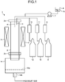
- FIG. 1 is a schematic view illustrating a configuration of a synthesizing apparatus for synthesizing carbon nanotube aggregates used in Examples of the present invention.
- the present invention includes a method for producing a carbon nanotube-containing composition for synthesizing carbon nanotube aggregates including the step of introducing a ferrocene derivative, a sulfur compound, a carbon source, and a carrier gas into a gas phase flowing in a heating furnace within a temperature range of higher than 1,200°C and 1,800°C or lower.
- the carbon source substantially consists of benzene or toluene.
- the carrier gas includes hydrogen in a range of 10% by volume or higher and 85% by volume or lower.
- the carrier gas has a linear velocity in a range of 230 cm/min or higher and 2,200 cm/min or lower.
- hydrogen is included in the carrier gas in a range of 10% by volume or higher and 85% by volume or lower and the remainder is preferably an inert gas.
- inert gas refers to an inert gas generally referred to, which means a rare gas such as helium, neon, argon, and xenon and a nitrogen gas.
- the reason why a mixed gas of hydrogen and the inert gas is used as a carrier gas is considered to be that adsorption of hydrogen atoms to an iron particle catalyst surface and activation of the iron particle catalyst surface are involved in decomposition of the carbon source.
- hydrogen is considered to activate an iron surface by reducing iron.
- Hydrogen also has the property of adsorbing on a transition metal surface. Consequently, when the amount of hydrogen is excessively large, the amount of hydrogen adsorbed on the iron particle catalyst surface is so large that reaction between the iron particle catalyst and the carbon source becomes difficult. This may result in reduction in the yield of the carbon nanotube aggregates. Therefore, the hydrogen is required to be diluted with the appropriate amount of the inert gas to such an extent that the reaction is not inhibited while the hydrogen necessary for activating the iron particle catalyst surface is being ensured.
- hydrogen also serves to recover the thermally decomposed C-H bonds to their original state, whereas hydrogen reacts with an unsaturated bond of the organic compound to promote thermal decomposition. Consequently, the concentration of hydrogen is finally required to be adjusted according to the carbon source to be used.
- the content of the hydrogen included in the carrier gas is preferably set within the above range.
- the hydrogen gas when the total volume ratio of the introduced carrier gas is 100% by volume, the hydrogen gas is in a range of 25% by volume or higher and 65% by volume or lower and preferably in a range of 30% by volume or higher and 55% by volume or lower.
- the content of hydrogen is preferably adjusted to be higher when the ratio of the single-walled CNT is desired to be increased, whereas the content of hydrogen is preferably adjusted to be lower when the ratio of the double-walled CNT is desired to be increased.
- the most preferable content of hydrogen is in a range of 35% by volume or higher and 45% by volume or lower.
- the content of hydrogen is preferably adjusted in a range of 45% to 85%.
- the amount of hydrogen included in the carrier gas within the above-described range, carbon nanotube aggregates having high crystallinity and high purity can be synthesized in high yield.
- the content of hydrogen most notably affects the easiness of decomposition of the carbon source.
- the hydrogen content also tends to relate to change in heat transfer in the carrier gas and the growth rate of the iron particle catalyst.
- the synthesis temperature is set to be higher, the carbon source is more likely to be thermally decomposed and thus, in order to reduce the decomposition amount of the carbon source, the content of hydrogen is preferably adjusted to be higher.
- the synthesis temperature is set to be lower, in order to facilitate decomposition of the carbon source, the content of hydrogen is preferably adjusted to be lower.
- the carbon source When the content of hydrogen is lower than 10% by volume, the carbon source is decomposed so much that side reactions take place excessively and thus a large amount of by-products other than CNT are produced. This results in decrease in the yield of CNT itself.
- the content of hydrogen exceeds 85% by volume, the decomposition of the carbon source becomes insufficient and the yield of the carbon nanotube aggregates decreases. Consequently, when the influence of other synthesis conditions (temperature, linear velocity of carrier gas, catalyst introduction amount, carbon source ratio, ferrocene derivative ratio, sulfur compound ratio, and the like) is increased, the conditions are preferably determined to be based on the above ranges.
- the temperature of the heating furnace is set within a temperature range of 1,150°C to 1,800°C or lower in order to appropriately carry out thermal decomposition of the carbon source (aromatic compound in the present invention) matching the mixing ratio of the carrier gas.
- the raw materials to be used, the catalyst, and the carrier gas flow through a pipe installed in the heating furnace in order to heat these substances.
- the material of the pipe ceramics, alumina, quartz, silicon carbide, and the like can be used.
- the pipe becomes more preferable with a thinner wall to easily conduct heat as long as the pipe is thick enough to withstand normal use.
- the thickness is usually preferably about 1 mm or thicker and about 5 mm or thinner when the inner diameter of the pipe is about 8 cm or smaller and the thickness is preferably about 5 mm or thicker and about 10 mm or thinner when the inner diameter of the pipe is about larger than 8 cm because the pipe is difficult to break.
- the upper limit of the thickness is not particularly limited as long as heat can be efficiently transferred from the heating furnace to the inside of the pipe and the thickness is preferably set to a thickness being easy to handle.
- the temperature of the heating furnace at this time refers to a temperature of the thermometer (for example, a thermocouple for measuring the temperature) measured by locating the measurement part of the thermometer at a distance within 2 mm from the surface of the pipe through which the carrier gas and the raw materials are passed in order to synthesize CNT and without contacting the pipe.
- a method of heating the inside of the pipe for CNT synthesis by inserting a heating element into the pipe instead of heating the pipe from the outside can be used.
- the temperature of the heating furnace in this case refers to the temperature of a thermometer measured within 2 mm from the surface of the heating element without contacting the measurement part of the thermometer.
- a method of introducing a previously heated carrier gas into the pipe and simultaneously heating the pipe from outside can also be used.
- the temperature of the heating furnace refers to a higher temperature between the temperature measured at the time of installing the measurement part of a thermometer at the center of the pipe (position evenly far from the wall surface) and the temperature measured at a position where the distance from the outer surface of the pipe is within 2 mm.
- the carbon nanotube aggregates can be synthesized more efficiently and thus the temperature is preferably set as high as possible.
- the upper limit is generally about 1,800°C.
- the temperature of the heating furnace is preferably higher temperature from the viewpoint of ease of decomposition of the carbon source.
- the temperature is more preferably in a range of higher than 1,200°C and 1,500°C or lower and, from the same reason, the temperature is most preferably controlled in a range of 1,250°C or higher and 1,400°C or lower because an appropriate decomposition rate is difficult to adjust in consideration of other synthesis conditions.
- the temperature can be adjusted in a range of 1,400°C or lower and thus the temperature can be simply adjusted in a range of higher than 1,200°C and 1,400°C or lower.
- the temperature can also be adjusted in a range of higher than 1,150°C to 1,800°C. From the viewpoint that the carbon source is more easily decomposed by adjusting at a higher temperature, the temperature is preferably adjusted in a range of higher than 1,200°C and 1,800°C or lower.
- the carrier gas is also preferably previously preheated in a range of 200°C or higher and 1,100°C or lower.
- the preheating temperature is more preferably in a range of 400°C or higher and 1,100°C or lower, further preferably in a range of 500°C or higher and 1,100°C or lower, further more preferably in a range of 600°C or higher and 1,100°C or lower, and most preferably in a range of 700°C or higher and 1,000°C or lower.
- the length of the heating zone is preferably longer in order to sufficiently heat the flowing carbon source.
- the heating zone preferably has a length of 60 cm or longer, more preferably 100 cm or longer, and further preferably 150 cm or longer. As the length of the heating zone becomes longer, the heating zone is preferable. The heating zone having a length of at most about 50 cm, however, is considered to be sufficient because the carbon source is completely decomposed if the heating zone is excessively long.
- carbon nanotube aggregates having high crystallinity and high purity can be synthesized by using a carbon source consisting essentially of the aromatic compound as the carbon source.
- benzene or toluene can be suitably used as the carbon source.
- Benzene or toluene can be suitably used as a carbon source from the viewpoint that side reactions are less likely to occur.
- Benzene is the most preferable carbon source from the viewpoint that the side reactions are less likely to occur due to the absence of a functional group and that highly pure carbon nanotube aggregates can be obtained.
- toluene is also preferable as a carbon source because toluene is easy to handle from the viewpoint that volatility is not too high and not too low and toluene causes few side reactions.
- a carbon source consisting essentially of benzene or toluene is used as the carbon source.
- aliphatic or alicyclic hydrocarbons for example, methane, ethane, ethylene, acetylene, propane, propene, butane, butene, pentane, cyclopentane, hexane, cyclohexane, and decalin
- methane, ethane, ethylene, acetylene, propane, propene, butane, butene, pentane, cyclopentane, hexane, cyclohexane, and decalin may be mixed within the range not impairing the effect of the present invention.
- the upper limit of the addition amount is determined so that the number of the carbon atoms of the hydrocarbon to be added is 15% or lower relative to the introduction number of carbon atoms forming the aromatic ring of benzene or toluene to be introduced. From the viewpoint of the yield and the purity of the carbon nanotube aggregates to be obtained, as the addition amount of the hydrocarbon becomes smaller, the carbon source is more preferable.
- the addition amount is preferably 5% or lower.
- a compound that is not in the form of an aromatic compound before being introduced into the heating furnace but is converted into an aromatic compound after being introduced into the heating furnace for example, a compound, such as an iron complex having a structure in which a part of an aromatic ring is oxidatively added to an iron atom, that generates an aromatic ring by reductive elimination in the course of thermal decomposition
- a compound that is not in the form of an aromatic compound before being introduced into the heating furnace but is converted into an aromatic compound after being introduced into the heating furnace for example, a compound, such as an iron complex having a structure in which a part of an aromatic ring is oxidatively added to an iron atom, that generates an aromatic ring by reductive elimination in the course of thermal decomposition
- the existence of such a compound is substantially the same as the use of the aromatic compound as the carbon source and thus such a compound can also be used.
- a ferrocene derivative is simultaneously introduced with the carbon source as an iron source producing the iron particle catalyst.
- the reason why the ferrocene derivative is preferable is presumably that the decomposition rate of the skeleton around the iron atom of the molecule having the ferrocene skeleton and the formation rate of the iron particles associated with the decomposition may be moderately preferable within the mixing ratio of the carrier gas and the temperature range determined in the present invention.
- a ferrocene derivative having a functional group having up to 6 carbon atoms or a ferrocene derivative having an aromatic group and including at most 6 atoms (excluding carbon) other than carbon atoms in the functional group for example, a ferrocene derivative having a functional group such as a methyl group, an ethyl group, a propyl group, a butyl group, a pentyl group, an acetyl group, a carboxy group, a hydroxy group, an amino group, and an epoxy group can be used and a ferrocene derivative having an aromatic group such as a phenyl group, an anisyl group, and a phenol group and having a heterocyclic compound including a hetero atom as a functional group can also be used.
- the heteroatom has a property of adsorbing to a transition metal and thus, in the range defined by the present invention, has a function of activating the catalyst surface when the amount of the heteroatom is small as described above.
- the reaction will be affected. Therefore, the less amount of the heteroatom is preferable.
- the aromatic group when the aromatic group has a simple structure such as a phenyl group, the aromatic group acts as a carbon source similar to the carbon source of the aromatic compound after decomposition and thus no particular problem arises.
- the functional group having carbon atoms is left from ferrocene in the course of thermal decomposition and decomposes at a different rate from the aromatic compound to act as a carbon source.
- the amount of the functional groups when the amount of the functional groups is excessively large, the balance with the growth rate of the iron particle catalyst is shifted and thus the side reactions proceed. Consequently, the amount of the functional groups is preferable to the extent as described above.
- the functional groups do not only inhibit the reaction but also are reacted with the small amount of the iron particle catalyst deviating from the optimum conditions to provide the carbon nanotube aggregates and, as a result, the functional groups hardly affect the reaction.
- ferrocene is most preferably used from the viewpoint of easy formation of uniform carbon nanotube aggregates provided by the uniformity of the decomposition.
- ferrocene is preferable as compared with other ferrocene derivatives from the viewpoint of ease of handling.
- the reason is considered to be that, in the temperature range of the present invention, the C-S bond or the S-S bond of the sulfur compound is easily cleaved and the sulfur compound is easily decomposed in the reaction tube and thus influence of the change in the kind of the sulfur compound is small and the synthesis is carried out in high yield and high efficiency.
- the suitable sulfur compound include sulfur (crystalline form and non-crystalline form), a thiophenol derivative, a phenyl sulfide derivative, a phenyl disulfide derivative, carbon disulfide, and a thiophene derivative.
- a compound in which the number of other atoms with respect to the sulfur atom is 10 or less is preferably used and thiophene is more preferably used.
- the decomposition rate is the most suitable rate within the scope of the present invention and no functional groups inducing side reactions are included.
- the ratio of the carbon source, the thiophene derivative, and the sulfur compound is preferably 1 part by weight or more and 10 parts by weight or less of the ferrocene derivative and 1 part by weight or more and 10 parts by weight or less of the sulfur compound relative to 50 parts by weight or more and 250 parts by weight or less of the carbon source.
- the supply amount of the carbon source is preferably adjusted to about 10 ⁇ L/min or higher and about 400 ⁇ L/min or lower. When the supply amount is large, the carbon source tends to be wasted. On the other hand, when the supply amount is small, the catalyst tends to be wasted and thus side reactions easily occur.
- the supply amount is more preferably adjusted in a range of 50 ⁇ L/min or higher and 300 ⁇ L/min or lower.
- the most preferable supply amount is in a range of 75 ⁇ L/min or higher and 150 cc/min or lower.
- the solid carbon source is preferably supplied by melting or supplied by sublimating the solid carbon source.
- the supply amount thereof is preferably calculated so that the supply amount in the case of the solid carbon source corresponds to the supply amount in the case of liquid carbon source so as to be equalized in terms of the number of moles.
- the decomposition temperature and the decomposition rate of the carbon source, the ferrocene derivative, and the sulfur compound are different from each other and the heating method of the heating furnace is different, the decomposition rate is shifted and thus the ratio of the carbon source, the ferrocene derivative, and the sulfur is required to be finely adjusted.
- the carbon source, the ferrocene derivative, and the sulfur compound are preferably mixed and collectively introduced as a catalyst and carbon source solution into the heating furnace.
- the carbon source, the ferrocene derivative, and the sulfur compound can be introduced into the heating furnace while the ratio of them is being kept constant.
- the carbon source is preferably in a liquid state at normal temperature and normal pressure from the viewpoint of ease of handling.
- the carbon source in a liquid state, even when the ferrocene derivative and the sulfur compound are solid, these substances can be dissolved in the carbon source in a liquid state to form a catalyst and carbon source solution.
- the carbon source may be melted and mixed with the ferrocene derivative and the sulfur compound.
- the synthesis is preferably carried out after providing a mechanism for mixing in the heating furnace so that the ratio of each of the carbon source, the ferrocene derivative, and the sulfur compound is kept constant.
- the temperature range of the synthesis of the carbon nanotube aggregates using the aromatic compound as the carbon source, the mixed gas of hydrogen and the inert gas as a carrier gas, and the ferrocene derivative and the sulfur compound is preferably in a range of higher than 1,150°C and 1,800°C or lower.
- this temperature is relatively higher than that of the known floating catalyst method, one reason is that aromatic compounds are used as the carbon source.
- Aromatic compounds generally require a higher temperature for decomposition than that of saturated hydrocarbons.
- the carbon nanotube aggregates are synthesized at a low temperature, only a part of carbon sources are decomposed and thus the yield does not increase. Therefore, when the synthesis is carried out at relatively low temperature, hydrocarbons and alcohols are often used as carbon sources. The yield, however, is usually not so high.
- the reason why the yield of highly pure carbon nanotube aggregates is remarkably high under the conditions of the present invention may be that the synthesis is carried out at relatively high temperature.
- Thermal decomposition of a carbon source is generally an endothermic reaction in which the carbon source is decomposed by heating.
- a large amount of carbon nanotube aggregates are intended to be efficiently and continuously synthesized, a large amount of the carbon source is required to be charged and a large amount of heat is required.
- setting the synthesis temperature at remarkably high temperature causes significant side reactions, which causes a decrease in yield.
- the aromatic compound that decomposes at a relatively high temperature is used as the carbon source, so that side reactions are less likely to occur, much heat can be added, and this carbon source is suitable for mass production.
- the synthesis temperature is more preferably in a range of higher than 1,200°C and 1,400°C or lower, which is a higher temperature.
- the temperature is excessively high, the uniformity of the carbon nanotube aggregates (diameter distribution and crystallinity) tend to be disturbed and to be difficult to adjust. As a result, the quality of the carbon nanotube aggregates may deteriorate. Consequently, when the temperature is in a range of higher than 1,200°C and 1,300°C or lower, the uniformity as well as the yield and efficiency of the carbon nanotube aggregates can be easily secured, which is most preferable.
- the temperature is preferably adjusted in a range of 1,250°C or higher and 1,400°C or lower, depending on the linear velocity of the carrier gas and the mixing ratio, even if some disturbance occurs.
- the temperature is appropriately adjusted to a higher temperature side as the linear velocity of the carrier gas is increased, whereas the temperature is adjusted to a lower temperature side as the ratio of the inert gas is increased.
- the linear velocity of the carrier gas is increased, the temperature is required to be raised because a lot of heat is taken away.
- the ratio of the inert gas is changed, the temperature is required to be adjusted to a higher temperature when heat is difficult to transmit and the temperature is required to be adjusted to a lower temperature when heat is easy to transmit with reference to specific heat, because the thermal conductivity in the carrier gas changes.
- the decomposition of the carbon source tends to be reduced when the concentration of hydrogen is increased and thus, when the content of hydrogen is increased, the temperature is appropriately adjusted to a higher temperature in order to promote the thermal decomposition of the carbon source.
- the temperature is required to be adjusted to a lower temperature in order to prevent the side reactions from proceeding because the decomposition of the carbon source becomes easy to proceed.
- the reason why the linear velocity of the carrier gas is in a range of 230 cm/min or higher and 2,200 cm/min or lower is considered to be related to the thermal conductivity of the carrier gas and the thermal decomposition rate of the carbon source to be used.
- the linear velocity is adjusted within the above range depending on the difference in heat transfer, the carbon nanotube aggregates can be synthesized in high yield. Consequently, when the temperature is preferably set relatively high, the linear velocity of the carrier gas is adjusted to a higher velocity, whereas when the temperature is preferably set relatively low, the linear velocity of the carrier gas is adjusted to a lower velocity.
- variation of the convective state of the carrier gas depending on the linear velocity is also considered to affect the synthesis.
- the linear velocity of the carrier gas adjusted in a range of 230 cm/min or higher and 1,400 cm/min or lower allows the highly pure carbon nanotube aggregates to be obtained in high yield.
- the carbon nanotube aggregates can be obtained in higher yield by adjusting the linear velocity of the carrier gas in a range of higher than 1,400 cm/min and 2,200 cm/min or lower.
- the linear velocity of the carrier gas is preferably adjusted in a range of 230 cm/min or higher and 1,400 cm/min or lower, in the case where the heating furnace temperature is higher than 1,150°C and 1,300°C or lower, the linear velocity of the carrier gas is preferably adjusted in a range of 1,100 cm/min or higher and 2,200 cm/min or lower, in the case where the heating furnace temperature is higher than 1,300°C and 1,600°C or lower, and the linear velocity of the carrier gas is preferably adjusted in a range of 1,600 cm/min or higher and 2,200 cm/min or lower, in the case where the heating furnace temperature is higher than 1,600°C and 1,800°C or lower.
- the carbon nanotube aggregates can also be synthesized under conditions outside the above range depending on other condition settings.
- the linear velocity of the carrier gas is preferably adjusted to a faster velocity when the thermal conductivity of the carrier gas becomes higher, whereas the linear velocity of the carrier gas is preferably adjusted to a slower velocity when the thermal conductivity becomes lower.
- the aromatic compound as the carbon source is suitably thermally decomposed and the carbon nanotube aggregates are efficiently synthesized. Since the region where the linear velocity of the carrier gas is slow is influenced by convection, the other synthesis conditions are difficult to adjust. In the region where the linear velocity of the carrier gas is fast, the errors of the other synthesis conditions tend to become large.
- the range of the linear velocity of the carrier gas that is more easily adjustable is preferably in a range of 500 cm/min or higher and 1,800 cm/min or lower.
- the linear velocity is in a range of 900 cm/min or higher and 1,400 cm/min or lower, the other synthesis conditions are easily adjusted.
- carbon nanotube aggregates having any ratio of 20% or higher of the double-walled CNT can be synthesized and, under suitable conditions, carbon nanotube aggregates in which the amount of the double-walled CNT is 50% or higher can be synthesized.
- the term "50% or higher” used herein means that when 200 CNTs are observed with a transmission electron microscope, 100 or more CNTs observed are double-walled CNTs.
- the counting of 200 CNTs is carried out by observing the CNTs at a magnification of 250,000 times or higher with a transmission electron microscope, observing more than 20 visual fields of the visual fields in which the diameter and the number of layers of 10 or more CNTs in one visual field can be determined, and counting the number of layers and the number of CNTs in each of the visual fields. The same applies to other arbitrary ratios.
- the double-walled CNT has a higher carbon consumption rate per unit time for growing than that of the single-walled CNT in the adjustment method of the double-walled CNT at an arbitrary ratio. Consequently, the ratio of the formation of the double-walled CNT increases when the synthesis conditions are adjusted in such a direction that the thermal decomposition amount of the carbon source in the system increases, whereas the ratio of formation of the double-walled CNT decreases when the conditions are adjusted in such a way that the carbon source thermally decomposed in the system decreases.
- the ratio of the double-walled CNT in the carbon nanotube aggregates is increased, whereas when the volume ratio of hydrogen in the carrier gas is increased, the ratio of the double-walled CNT is decreased.
- the ratio of the double-walled CNT in the carbon nanotube aggregates increases, whereas as the synthesis temperature is decreased, the ratio of the double-walled CNT is decreased.
- the linear velocity of the carrier gas is decreased, the ratio of the double-walled CNT in the carbon nanotube aggregates is increased, whereas as the linear velocity of the carrier gas is increased, the ratio of the double-walled CNT is decreased.
- the carbon source introduction amount is increased, the ratio of the double-walled CNT in the carbon nanotube aggregates is increased, whereas as the carbon source introduction amount is decreased, the ratio of the double-walled CNT is decreased.
- the ratio of the hydrogen gas in the carrier gas and the synthesis temperature provide the most significant influence on the ratio of the double-walled CNT.
- the synthesis temperature is in the range of 1,150°C or higher and 1,800°C or lower and more preferably in the range of 1,200°C or higher and 1,800°C or lower.
- the synthesis temperature is more preferably in a range of 1,250°C or higher and 1,800°C or lower and the carbon nanotube aggregates are preferably synthesized in a range of 1,250°C or higher and 1,500°C or lower from the viewpoint of ease of adjustment of other synthesis conditions.
- the hydrogen ratio in the carrier gas is in the range of 10% by volume or higher and 85% by volume or lower.
- the carbon source tends to be decomposed with less hydrogen and thus the hydrogen ratio is preferably in a range of 10% by volume or higher and 60% by volume or lower and more preferably in a range of 15% by volume or higher and 50% by volume or lower.
- hydrogen ratio is preferably in a range of 25% by volume or higher and 45% by volume or lower.
- the carbon source introduced amount is preferably as much as possible to the extent that unfavorable side reactions do not occur.
- the linear velocity of the carrier gas may be arbitrary within the scope of the present invention. When the adjustment cannot be carried out under the above-described condition setting, the ratio of the double-walled CNT can be increased by slowing the linear velocity of the carrier gas.
- the introduction ratio of the ferrocene derivative and the sulfur compound is adjusted such that the sulfur atoms contained in the sulfur compound are in the range of 0.14 mol or more and 0.22 mol or less per 1 mol of the iron atoms included in the ferrocene derivative, whereby the carbon nanotube aggregates including 50% or higher of the single-walled CNT can be obtained.
- the single-walled CNT can be more suitably obtained.
- the above-described ratio is more preferably adjusted in a range of 0.15 mol or more and 0.22 mol or less and most preferably adjusted in a range of 0.15 mol or more and 0.20 mol or less.
- carbon nanotube aggregates having a G/D ratio of 50 or higher can be synthesized in high yield and, under suitable conditions, the carbon nanotube aggregates having a G/D ratio of 80 or higher, which is generally considered to be high purity, can be synthesized. Under more suitable conditions, the carbon nanotube aggregates having a G/D ratio of 100 or higher, which means that the carbon nanotube aggregates have remarkably high purity, can be synthesized.
- G/D ratio used herein means the ratio of the height of the G band to the height of the D band in Raman spectrum by Raman spectroscopic analysis using laser light having a wavelength of 532 nm.
- TGA curve means the differential curve (DTG) of a TGA curve when a sample of about 1 mg is placed in a differential thermal analyzer (for example, DTG-60, manufactured by Shimadzu Corporation) and the temperature is raised from room temperature to 950°C at a temperature rising rate of 10 °C/min in air.
- a differential thermal analyzer for example, DTG-60, manufactured by Shimadzu Corporation
- a powder sample was placed in a resonance Raman spectrometer (INF-300, manufactured by HORIBA Jobin Yvon GmbH) and measurement was made using a laser wavelength of 532 nm. When the G/D ratio was measured, the analysis was carried out at three different parts of the sample, and the arithmetic mean thereof was determined.
- a differential thermal analyzer (DTG-60, manufactured by Shimadzu Corporation) and the temperature was raised from room temperature to 950°C at a temperature rising rate of 10 °C/min in air.
- the peak temperature of weight loss was read from the differential curve (DTG) of the TGA curve at this time.
- FIG. 1 is a schematic view of the apparatus for synthesizing carbon nanotube aggregates according to Examples.
- the synthesizing apparatus 1 illustrated in FIG. 1 includes a mullite vertical reaction tube 2, a heating furnace 3, a liquid spray nozzle 4, a carrier gas introduction port 5, a micro-feeder 6, a pump 7, cylinders 8, 10, 12, a carrier gas flowmeter 9, 11, 13, and a collecting box 14.
- the mullite vertical reaction tube 2 is a reaction tube for synthesizing carbon nanotube aggregates having an inner diameter of 52 mm, an outer shape of 60 mm, a length of 1500 mm, and an inner effective heating length of 1100 mm.
- the heating furnace 3 is a device that is located around the outer periphery of the mullite vertical reaction tube 2, generates heat by energization, and heats the inside of the mullite vertical reaction tube 2 by the generated heat.
- the liquid spray nozzle 4 is located at an upper flange 2a of the mullite vertical reaction tube 2 and sprays a carbon source made of an aromatic compound into the mullite vertical reaction tube 2 in a mist form.
- the carrier gas introduction port 5 is located at the upper flange 2a of the mullite vertical reaction tube 2 and introduces the carrier gas into the mullite vertical reaction tube 2.
- the micro-feeder 6 stores a catalyst and carbon source solution 15 prepared by mixing the aromatic compound in a liquid state at normal temperature and normal pressure as the carbon source, ferrocene (manufactured by Wako Pure Chemical Industries, Ltd.) being an organic transition metal compound, and thiophene (manufactured by KANTO CHEMICAL CO., INC.) being an organic sulfur compound.
- the pump 7 adjusts the supply amount of the catalyst and carbon source solution 15 from the micro-feeder 6 to the liquid spray nozzle 4.
- the cylinder 8 stores a carrier gas also serving as a gas for spraying the catalyst and carbon source solution.
- the carrier gas flowmeter 9 adjusts the flow rate of the carrier gas supplied from the cylinder 8 to the liquid spray nozzle 4.
- the cylinder 10 stores hydrogen as the carrier gas.
- the carrier gas flowmeter 11 adjusts the carrier gas flow rate supplied from the cylinder 10 to the carrier gas introduction port 5.
- the cylinder 12 stores an inert gas as the carrier gas.
- the carrier gas flowmeter 13 adjusts the carrier gas flow rate supplied from the cylinder 12 to the carrier gas introduction port 5.
- the collecting box 14 is located under a lower flange 2b of the mullite vertical reaction tube 2 and separates the synthesized carbon nanotube aggregates and the synthesized product other than the carbon nanotube aggregates with a metal mesh 14a to collect the carbon nanotube aggregates.
- a waste gas pipe 14b for the mixed carrier gas after synthesis exhausted as an exhaust gas is located in the lower part of the collecting box 14.
- Examples 1 to 3 are results when the linear velocity of the carrier gas is changed. In every case, highly pure carbon nanotube aggregates were able to be synthesized in a yield of 1.5 g/h or higher.
- Examples 4 to 7 are examples in which the content of hydrogen is changed. In every case, carbon nanotube aggregates having a high G/D ratio and high heat resistance were able to be synthesized in a remarkably high yield of 1.6 g/h or higher.
- Example 8 is an example in which the type of the inert gas is changed to nitrogen.
- Example 9 is an example when the carbon source is changed from toluene to benzene and Examples 10 and 11 are examples in which the synthesis temperature is changed. In every case, excellent carbon nanotube aggregates were synthesized in high yield.
- Example 12 is an example showing that high quality carbon nanotube aggregates can be obtained in higher yield by adjusting the synthesis conditions.
- Example 13 is an example in which the introduction amount of the catalyst and carbon source solution was increased and the linear velocity of the carrier gas was increased from the conditions of Example 12, and, as a result, the yield of the highly pure carbon nanotube aggregates was further increased.
- Table 2 lists examples in which each of carbon nanotube aggregates having a ratio of the single-walled CNT of 50% or higher and carbon nanotube aggregates having a ratio of the double-walled CNT of 50% or higher can be separately produced by adjusting the molar ratio of simultaneously introduced sulfur atoms to the number of moles of iron atoms introduced as a catalyst and the layer number ratios of the CNTs contained in the carbon nanotube aggregates in order to show that the ratio of the double-walled CNT in the high quality carbon nanotube aggregates obtained in high yield can be adjusted by various other synthesis conditions (Examples 5, 14 to 17).
- Comparative Examples 1 to 3 are examples in which carbon nanotube aggregates were synthesized using decalin (decahydronaphthalene) being an aliphatic hydrocarbon as the carbon source instead of the aromatic compound. The yields were significantly low and the purities of the carbon nanotube aggregates determined from G/D ratios and DTG peak temperatures were also significantly low.
- Comparative Examples 4 to 6 are synthesis examples when a gaseous hydrocarbon is additionally introduced. When ethylene or methane was additionally introduced or both of ethylene and methane were additionally introduced at the same time, the yields of substantially obtained carbon nanotube aggregates were small because the purity was high but the yield was low or the yield was high but the purity was significantly low.
- the ratio of the number of carbon atoms of the additional carbon source to the number of carbon atoms forming the aromatic ring of the introduced aromatic compound (toluene) was 34% in Comparative Example 4, 95% in Comparative Example 5, or 455% in Comparative Example 6.
- Comparative Example 7 is an example when the synthesis temperature was 1,100°C. No carbon nanotube aggregates were produced.
- Comparative Example 8 is an example when the carrier gas is 100% hydrogen and, also in this case, no carbon nanotube aggregates was able to be obtained.
- Comparative Example 9 when the carrier gas was 100% of argon, amorphous carbon was mainly produced and almost no carbon nanotube aggregates were produced.
- Comparative Example 10 is an example in which the sulfur compound was not introduced and amorphous carbon was mainly produced and almost no carbon nanotube aggregates were produced.
- Comparative Example 11 is an example in which no ferrocene derivative was introduced and no recoverable carbon materials were produced.
- the highly pure carbon nanotube aggregates can be synthesize in high efficiency and high yield.
Landscapes
- Chemical & Material Sciences (AREA)
- Engineering & Computer Science (AREA)
- Nanotechnology (AREA)
- Organic Chemistry (AREA)
- Materials Engineering (AREA)
- Crystallography & Structural Chemistry (AREA)
- Chemical Kinetics & Catalysis (AREA)
- Physics & Mathematics (AREA)
- Condensed Matter Physics & Semiconductors (AREA)
- General Physics & Mathematics (AREA)
- Inorganic Chemistry (AREA)
- Manufacturing & Machinery (AREA)
- Composite Materials (AREA)
- Thermal Sciences (AREA)
- Carbon And Carbon Compounds (AREA)
- Electric Double-Layer Capacitors Or The Like (AREA)
Abstract
Description
- The present invention relates to a method for producing a carbon nanotube-containing composition. Background
- Except for special cases, a structure of a carbon nanotube (hereinafter may be abbreviated as "CNT") is often classified into a single-walled CNT having a structure in which only one layer of graphite is wound in a tubular shape, a double-walled CNT in which two layers of graphite form a tubular structure, and a multi-walled CNT in which a plurality of layers of graphite of three or more layers form a concentric cylindrical tubular structure. CNT has attracted attention for more than 10 years as a nanomaterial having excellent mechanical properties, excellent thermal conductivity, and excellent electrical conductivity. Highly pure CNT, however, is difficult to produce in high productivity. In many cases, a low quality CNT is synthesized in large quantity or an inefficient synthetic method that can produce a remarkably highly pure CNT but cannot produce the sufficient amount of CNT for commercial use.
- In recent years, it has been announced that a synthesis method called a super growth method (formerly the National Institute of Advanced Industrial Science and Technology) can produce carbon nanotube aggregates (here, a state in which countless CNTs including impurities and additives are collected is determined as the carbon nanotube aggregates) having high purity and low impurities in large quantity. The super growth method refers to a method in which the yield of CNT per process is significantly increased by adding water to oxidize carbon impurities and thus preventing occurrence of the situation where a catalyst surface is covered with the carbon impurities during the synthesis to inactivate the catalyst. The added water, however, may provide damage for not only the carbon impurities but also CNT. In addition, when the production efficiency is considered, it is also a concern that the super growth method is a synthesis method based on a substrate method.
- On the other hand, a floating catalyst method has been known as a highly efficient synthesis method in which raw materials are continuously charged and CNT can be continuously recovered. A method for directly and continuously producing a fiber (thread) made of CNT by utilizing the continuity of the floating catalyst method has been developed (refer to Patent Literature 1). According to the method described in
Patent Literature 1, however, twisted yarns of CNTs are ultrafine fibers and only fibers that are difficult to use for applications requiring robustness can be synthesized because the yield of CNT per unit time is remarkably low. Although the yield is remarkably low, a method in which remarkably highly pure carbon nanotube aggregates can be synthesized has also been developed (refer to Patent Literature 2). In addition, methods of synthesizing carbon nanotube aggregates including a double-walled CNT by devising two or more of introduced raw materials and devising a mixture ratio of catalysts and the like have also been developed (refer toPatent Literatures 3 and 4). -
- Patent Literature 1: Japanese Patent Application Laid-open No.
2012-46841 - Patent Literature 2: Japanese Patent Application Laid-open No.
2013-35750 - Patent Literature 3: Japanese Patent Application Laid-open No.
2015-48263 - Patent Literature 4: Japanese Patent Application Laid-open No.
2006-45057 - The methods for producing carbon nanotube aggregates include many production methods characterized in yield, efficiency, purity, crystallinity, number of layers, and the like. Even if different methods or synthesis conditions are combined, however, synergistic effects do not always appear. Consequently, at present, a method for producing carbon nanotube aggregates having high crystallinity and high purity in high efficiency and high yield cannot be practically achieved.
- The present invention has been made in view of the above problems and an object of the present invention is to provide a method for producing a carbon nanotube-containing composition from which carbon nanotube aggregates having high purity can be synthesized in high efficiency and high yield.
- A method for producing a carbon nanotube-containing composition for synthesizing carbon nanotube aggregates according to the present invention includes: introducing a ferrocene derivative, a sulfur compound, a carbon source, and a carrier gas into a gas phase flowing in a heating furnace within a temperature range of higher than 1,200°C to 1,800°C, wherein the carbon source substantially consists of benzene or toluene, the carrier gas includes hydrogen in a range of 10% by volume to 85% by volume, and the carrier gas has a linear velocity in a range of 230 cm/min to 2,200 cm/min.
- In the above-described method for producing a carbon nanotube-containing composition according to the invention, the carrier gas includes at least one gas selected from nitrogen, argon, and helium in a range of higher than 15% by volume to lower than 90% by volume.
- In the above-described method for producing a carbon nanotube-containing composition according to the invention, sulfur atoms contained in the sulfur compound are included in a range of 0.15 mol to 0.20 mol per 1 mol of iron atoms included in the ferrocene derivative.
- In the above-described method for producing a carbon nanotube-containing composition according to the invention, the ferrocene derivative is ferrocene.
- In the above-described method for producing a carbon nanotube-containing composition according to the invention, the sulfur compound is thiophene.
- In the above-described method for producing a carbon nanotube-containing composition according to the invention, obtained carbon nanotube aggregates include double-walled carbon nanotubes.
- According to the method for producing the carbon nanotube-containing composition according to the present invention, the carbon nanotube aggregates having high purity can be synthesized in high efficiency and high yield.
-
FIG. 1 is a schematic view illustrating a configuration of a synthesizing apparatus for synthesizing carbon nanotube aggregates used in Examples of the present invention. - Hereinafter, Description of Embodiments of the present invention will be described in detail. The present invention, however, is not limited by the following embodiments.
- First, the present invention includes a method for producing a carbon nanotube-containing composition for synthesizing carbon nanotube aggregates including the step of introducing a ferrocene derivative, a sulfur compound, a carbon source, and a carrier gas into a gas phase flowing in a heating furnace within a temperature range of higher than 1,200°C and 1,800°C or lower. The carbon source substantially consists of benzene or toluene. The carrier gas includes hydrogen in a range of 10% by volume or higher and 85% by volume or lower. The carrier gas has a linear velocity in a range of 230 cm/min or higher and 2,200 cm/min or lower.
- It is important that hydrogen is included in the carrier gas in a range of 10% by volume or higher and 85% by volume or lower and the remainder is preferably an inert gas. The term "inert gas" as used herein refers to an inert gas generally referred to, which means a rare gas such as helium, neon, argon, and xenon and a nitrogen gas. In the present invention, the reason why a mixed gas of hydrogen and the inert gas is used as a carrier gas is considered to be that adsorption of hydrogen atoms to an iron particle catalyst surface and activation of the iron particle catalyst surface are involved in decomposition of the carbon source.
- In general, hydrogen is considered to activate an iron surface by reducing iron. Hydrogen, however, also has the property of adsorbing on a transition metal surface. Consequently, when the amount of hydrogen is excessively large, the amount of hydrogen adsorbed on the iron particle catalyst surface is so large that reaction between the iron particle catalyst and the carbon source becomes difficult. This may result in reduction in the yield of the carbon nanotube aggregates. Therefore, the hydrogen is required to be diluted with the appropriate amount of the inert gas to such an extent that the reaction is not inhibited while the hydrogen necessary for activating the iron particle catalyst surface is being ensured. In addition, hydrogen also serves to recover the thermally decomposed C-H bonds to their original state, whereas hydrogen reacts with an unsaturated bond of the organic compound to promote thermal decomposition. Consequently, the concentration of hydrogen is finally required to be adjusted according to the carbon source to be used.
- For these reasons, the content of the hydrogen included in the carrier gas is preferably set within the above range. Preferably, when the total volume ratio of the introduced carrier gas is 100% by volume, the hydrogen gas is in a range of 25% by volume or higher and 65% by volume or lower and preferably in a range of 30% by volume or higher and 55% by volume or lower. In addition, the content of hydrogen is preferably adjusted to be higher when the ratio of the single-walled CNT is desired to be increased, whereas the content of hydrogen is preferably adjusted to be lower when the ratio of the double-walled CNT is desired to be increased. Considering the balance between the yield and the crystallinity of CNT, the most preferable content of hydrogen is in a range of 35% by volume or higher and 45% by volume or lower. From the viewpoint of improving the yield, the content of hydrogen is preferably adjusted in a range of 45% to 85%. By setting the amount of hydrogen included in the carrier gas within the above-described range, carbon nanotube aggregates having high crystallinity and high purity can be synthesized in high yield.
- The content of hydrogen most notably affects the easiness of decomposition of the carbon source. In addition to this, the hydrogen content also tends to relate to change in heat transfer in the carrier gas and the growth rate of the iron particle catalyst. For example, when the synthesis temperature is set to be higher, the carbon source is more likely to be thermally decomposed and thus, in order to reduce the decomposition amount of the carbon source, the content of hydrogen is preferably adjusted to be higher. On the other hand, when the synthesis temperature is set to be lower, in order to facilitate decomposition of the carbon source, the content of hydrogen is preferably adjusted to be lower. When the content of hydrogen is lower than 10% by volume, the carbon source is decomposed so much that side reactions take place excessively and thus a large amount of by-products other than CNT are produced. This results in decrease in the yield of CNT itself. On the other hand, when the content of hydrogen exceeds 85% by volume, the decomposition of the carbon source becomes insufficient and the yield of the carbon nanotube aggregates decreases. Consequently, when the influence of other synthesis conditions (temperature, linear velocity of carrier gas, catalyst introduction amount, carbon source ratio, ferrocene derivative ratio, sulfur compound ratio, and the like) is increased, the conditions are preferably determined to be based on the above ranges.
- In the present invention, the temperature of the heating furnace is set within a temperature range of 1,150°C to 1,800°C or lower in order to appropriately carry out thermal decomposition of the carbon source (aromatic compound in the present invention) matching the mixing ratio of the carrier gas. At the time of synthesizing the carbon nanotube aggregates, the raw materials to be used, the catalyst, and the carrier gas flow through a pipe installed in the heating furnace in order to heat these substances. As the material of the pipe, ceramics, alumina, quartz, silicon carbide, and the like can be used. The pipe becomes more preferable with a thinner wall to easily conduct heat as long as the pipe is thick enough to withstand normal use. In general, a pipe having a thickness of 1 mm or thinner is difficult to handle because the pipe is easy to break. Consequently, in the case when the pipe is used for heating, depending on the material of the pipe, the thickness is usually preferably about 1 mm or thicker and about 5 mm or thinner when the inner diameter of the pipe is about 8 cm or smaller and the thickness is preferably about 5 mm or thicker and about 10 mm or thinner when the inner diameter of the pipe is about larger than 8 cm because the pipe is difficult to break.
- The upper limit of the thickness is not particularly limited as long as heat can be efficiently transferred from the heating furnace to the inside of the pipe and the thickness is preferably set to a thickness being easy to handle. In addition, the temperature of the heating furnace at this time refers to a temperature of the thermometer (for example, a thermocouple for measuring the temperature) measured by locating the measurement part of the thermometer at a distance within 2 mm from the surface of the pipe through which the carrier gas and the raw materials are passed in order to synthesize CNT and without contacting the pipe. By using the heating furnace in this temperature range, the carbon nanotube aggregates having high crystallinity and high purity can be obtained in high yield.
- In addition, in another embodiment, a method of heating the inside of the pipe for CNT synthesis by inserting a heating element into the pipe instead of heating the pipe from the outside can be used. The temperature of the heating furnace in this case refers to the temperature of a thermometer measured within 2 mm from the surface of the heating element without contacting the measurement part of the thermometer. In addition, in another embodiment, a method of introducing a previously heated carrier gas into the pipe and simultaneously heating the pipe from outside can also be used. In this case, the temperature of the heating furnace refers to a higher temperature between the temperature measured at the time of installing the measurement part of a thermometer at the center of the pipe (position evenly far from the wall surface) and the temperature measured at a position where the distance from the outer surface of the pipe is within 2 mm.
- As the temperature of the heating furnace becomes higher, the carbon nanotube aggregates can be synthesized more efficiently and thus the temperature is preferably set as high as possible. Considering the material of the facility and the durability of the heating element, however, the upper limit is generally about 1,800°C. When the temperature is in a range of higher than 1,200°C and 1,700°C or lower, the conditions for obtaining a highly crystalline carbon nanotube aggregates in high yield are easy to adjust, which is preferable. The temperature of the heating furnace is preferably higher temperature from the viewpoint of ease of decomposition of the carbon source. From the viewpoint of ease of control, however, the temperature is more preferably in a range of higher than 1,200°C and 1,500°C or lower and, from the same reason, the temperature is most preferably controlled in a range of 1,250°C or higher and 1,400°C or lower because an appropriate decomposition rate is difficult to adjust in consideration of other synthesis conditions.
- For example, when the heating furnace using a common Kanthal wire as the heating element is used, the temperature can be adjusted in a range of 1,400°C or lower and thus the temperature can be simply adjusted in a range of higher than 1,200°C and 1,400°C or lower. When the heating furnace using a heating element having higher purity or a heating element durable to high temperature (for example, Cantal Super and Keramax) is used, the temperature can also be adjusted in a range of higher than 1,150°C to 1,800°C. From the viewpoint that the carbon source is more easily decomposed by adjusting at a higher temperature, the temperature is preferably adjusted in a range of higher than 1,200°C and 1,800°C or lower.
- In the present invention, sufficient thermal decomposition of aromatic compounds that are relatively difficult to thermally decompose is important. Therefore, when sufficient heating cannot be carried out, the carrier gas is also preferably previously preheated in a range of 200°C or higher and 1,100°C or lower. As the preheating temperature becomes higher, decomposition of the carbon source in the heating furnace is more preferably carried out because the decomposition occurs more smoothly. The preheating temperature is more preferably in a range of 400°C or higher and 1,100°C or lower, further preferably in a range of 500°C or higher and 1,100°C or lower, further more preferably in a range of 600°C or higher and 1,100°C or lower, and most preferably in a range of 700°C or higher and 1,000°C or lower. When the preheating temperature is excessively high, the carbon source will be completely decomposed before synthesis of the carbon nanotube aggregates begins, so that the upper limit of the preheating temperature is at most 1,100°C.
- When heating is carried out using a general tubular furnace as the heating furnace, the length of the heating zone is preferably longer in order to sufficiently heat the flowing carbon source. In the present invention, depending on the size of the pipe in which the carbon source flows and is heated, when the pipe having an inner diameter of about 1 cm to 20 cm that is generally easily available is used, the heating zone preferably has a length of 60 cm or longer, more preferably 100 cm or longer, and further preferably 150 cm or longer. As the length of the heating zone becomes longer, the heating zone is preferable. The heating zone having a length of at most about 50 cm, however, is considered to be sufficient because the carbon source is completely decomposed if the heating zone is excessively long.
- By using benzene or toluene as a carbon source within the temperature range of the heating furnace and in the range of the mixing ratio of hydrogen and inert gas of the present invention, highly pure carbon nanotube aggregates can be synthesized in remarkably high yield and high efficiency compared with the general floating catalyst method of the same scale in the known example. In the present invention, carbon nanotube aggregates having high crystallinity and high purity can be synthesized by using a carbon source consisting essentially of the aromatic compound as the carbon source.
- As the carbon source, benzene or toluene can be suitably used. Benzene or toluene can be suitably used as a carbon source from the viewpoint that side reactions are less likely to occur. Benzene is the most preferable carbon source from the viewpoint that the side reactions are less likely to occur due to the absence of a functional group and that highly pure carbon nanotube aggregates can be obtained. In addition, toluene is also preferable as a carbon source because toluene is easy to handle from the viewpoint that volatility is not too high and not too low and toluene causes few side reactions.
- In the present invention, a carbon source consisting essentially of benzene or toluene is used as the carbon source. However, for the purpose of adjusting a specific heat, adjusting the degree of activity of the catalyst, or other reasons, aliphatic or alicyclic hydrocarbons (for example, methane, ethane, ethylene, acetylene, propane, propene, butane, butene, pentane, cyclopentane, hexane, cyclohexane, and decalin) may be mixed within the range not impairing the effect of the present invention. The upper limit of the addition amount is determined so that the number of the carbon atoms of the hydrocarbon to be added is 15% or lower relative to the introduction number of carbon atoms forming the aromatic ring of benzene or toluene to be introduced. From the viewpoint of the yield and the purity of the carbon nanotube aggregates to be obtained, as the addition amount of the hydrocarbon becomes smaller, the carbon source is more preferable. When the hydrocarbon is added to adjust the activity of the catalyst, the addition amount is preferably 5% or lower.
- When the hydrocarbon is excessively added, the side reactions excessively occur and thus the yield of the carbon nanotube aggregates may often be lowered due to inactivation of the catalyst or the like or the rate of thermal decomposition and the rate of catalyst particle growth do not match and thus carbon by-products may often be produced in a large quantity. In addition, a compound that is not in the form of an aromatic compound before being introduced into the heating furnace but is converted into an aromatic compound after being introduced into the heating furnace (for example, a compound, such as an iron complex having a structure in which a part of an aromatic ring is oxidatively added to an iron atom, that generates an aromatic ring by reductive elimination in the course of thermal decomposition) also exists. The existence of such a compound is substantially the same as the use of the aromatic compound as the carbon source and thus such a compound can also be used.
- In the present invention, a ferrocene derivative is simultaneously introduced with the carbon source as an iron source producing the iron particle catalyst. The reason why the ferrocene derivative is preferable is presumably that the decomposition rate of the skeleton around the iron atom of the molecule having the ferrocene skeleton and the formation rate of the iron particles associated with the decomposition may be moderately preferable within the mixing ratio of the carrier gas and the temperature range determined in the present invention. As the ferrocene derivative, a ferrocene derivative having a functional group having up to 6 carbon atoms or a ferrocene derivative having an aromatic group and including at most 6 atoms (excluding carbon) other than carbon atoms in the functional group, for example, a ferrocene derivative having a functional group such as a methyl group, an ethyl group, a propyl group, a butyl group, a pentyl group, an acetyl group, a carboxy group, a hydroxy group, an amino group, and an epoxy group can be used and a ferrocene derivative having an aromatic group such as a phenyl group, an anisyl group, and a phenol group and having a heterocyclic compound including a hetero atom as a functional group can also be used. The heteroatom has a property of adsorbing to a transition metal and thus, in the range defined by the present invention, has a function of activating the catalyst surface when the amount of the heteroatom is small as described above. However, as with hydrogen, when the heteroatom is introduced in an excessively large amount, the reaction will be affected. Therefore, the less amount of the heteroatom is preferable.
- In addition, when the aromatic group has a simple structure such as a phenyl group, the aromatic group acts as a carbon source similar to the carbon source of the aromatic compound after decomposition and thus no particular problem arises. However, in the case of hydrocarbons and other non-aromatic functional groups, the functional group having carbon atoms is left from ferrocene in the course of thermal decomposition and decomposes at a different rate from the aromatic compound to act as a carbon source. In the scope of the present invention, however, when the amount of the functional groups is excessively large, the balance with the growth rate of the iron particle catalyst is shifted and thus the side reactions proceed. Consequently, the amount of the functional groups is preferable to the extent as described above. When the amount of the functional groups is to the extent as described above, the functional groups do not only inhibit the reaction but also are reacted with the small amount of the iron particle catalyst deviating from the optimum conditions to provide the carbon nanotube aggregates and, as a result, the functional groups hardly affect the reaction. However, ferrocene is most preferably used from the viewpoint of easy formation of uniform carbon nanotube aggregates provided by the uniformity of the decomposition. In addition, ferrocene is preferable as compared with other ferrocene derivatives from the viewpoint of ease of handling.
- The reason why the sulfur compound is necessary in the present invention is not clear. The reason, however, is presumed to be that the direction in which CNT grows from the iron particle catalyst surface is determined by nonuniformly mixing the sulfur element in the iron particle catalyst. Therefore, according to the present invention, even when the type of the sulfur compound is changed, the carbon nanotube aggregates can be synthesized in remarkably high yield and high efficiency, compared with a similar general floating catalyst method having the same scale. The reason is considered to be that, in the temperature range of the present invention, the C-S bond or the S-S bond of the sulfur compound is easily cleaved and the sulfur compound is easily decomposed in the reaction tube and thus influence of the change in the kind of the sulfur compound is small and the synthesis is carried out in high yield and high efficiency. Examples of the suitable sulfur compound include sulfur (crystalline form and non-crystalline form), a thiophenol derivative, a phenyl sulfide derivative, a phenyl disulfide derivative, carbon disulfide, and a thiophene derivative. A compound in which the number of other atoms with respect to the sulfur atom is 10 or less is preferably used and thiophene is more preferably used. The reason for this is considered to be that the decomposition rate is the most suitable rate within the scope of the present invention and no functional groups inducing side reactions are included.
- In the present invention, the ratio of the carbon source, the thiophene derivative, and the sulfur compound is preferably 1 part by weight or more and 10 parts by weight or less of the ferrocene derivative and 1 part by weight or more and 10 parts by weight or less of the sulfur compound relative to 50 parts by weight or more and 250 parts by weight or less of the carbon source. In addition, in the case of a liquid carbon source, the supply amount of the carbon source is preferably adjusted to about 10 µL/min or higher and about 400 µL/min or lower. When the supply amount is large, the carbon source tends to be wasted. On the other hand, when the supply amount is small, the catalyst tends to be wasted and thus side reactions easily occur. Consequently, the supply amount is more preferably adjusted in a range of 50 µL/min or higher and 300 µL/min or lower. The most preferable supply amount is in a range of 75 µL/min or higher and 150 cc/min or lower.
- In the case of a solid carbon source, the solid carbon source is preferably supplied by melting or supplied by sublimating the solid carbon source. The supply amount thereof is preferably calculated so that the supply amount in the case of the solid carbon source corresponds to the supply amount in the case of liquid carbon source so as to be equalized in terms of the number of moles. In addition, when the decomposition temperature and the decomposition rate of the carbon source, the ferrocene derivative, and the sulfur compound are different from each other and the heating method of the heating furnace is different, the decomposition rate is shifted and thus the ratio of the carbon source, the ferrocene derivative, and the sulfur is required to be finely adjusted. In the present invention, the carbon source, the ferrocene derivative, and the sulfur compound are preferably mixed and collectively introduced as a catalyst and carbon source solution into the heating furnace. By introducing them collectively, the carbon source, the ferrocene derivative, and the sulfur compound can be introduced into the heating furnace while the ratio of them is being kept constant.
- Consequently, the carbon source is preferably in a liquid state at normal temperature and normal pressure from the viewpoint of ease of handling. In the case of the carbon source in a liquid state, even when the ferrocene derivative and the sulfur compound are solid, these substances can be dissolved in the carbon source in a liquid state to form a catalyst and carbon source solution. When the carbon source is solid, the carbon source may be melted and mixed with the ferrocene derivative and the sulfur compound. Alternatively, when there is a reason for separately introducing the raw materials into the heating furnace, the synthesis is preferably carried out after providing a mechanism for mixing in the heating furnace so that the ratio of each of the carbon source, the ferrocene derivative, and the sulfur compound is kept constant.
- In the present invention, the temperature range of the synthesis of the carbon nanotube aggregates using the aromatic compound as the carbon source, the mixed gas of hydrogen and the inert gas as a carrier gas, and the ferrocene derivative and the sulfur compound is preferably in a range of higher than 1,150°C and 1,800°C or lower. As the reason why this temperature is relatively higher than that of the known floating catalyst method, one reason is that aromatic compounds are used as the carbon source. Aromatic compounds generally require a higher temperature for decomposition than that of saturated hydrocarbons. When the carbon nanotube aggregates are synthesized at a low temperature, only a part of carbon sources are decomposed and thus the yield does not increase. Therefore, when the synthesis is carried out at relatively low temperature, hydrocarbons and alcohols are often used as carbon sources. The yield, however, is usually not so high.
- In addition, the reason why the yield of highly pure carbon nanotube aggregates is remarkably high under the conditions of the present invention may be that the synthesis is carried out at relatively high temperature. Thermal decomposition of a carbon source is generally an endothermic reaction in which the carbon source is decomposed by heating. When a large amount of carbon nanotube aggregates are intended to be efficiently and continuously synthesized, a large amount of the carbon source is required to be charged and a large amount of heat is required. When a carbon source decomposing at relatively low temperature is used, however, setting the synthesis temperature at remarkably high temperature causes significant side reactions, which causes a decrease in yield. Therefore, when the carbon nanotube aggregates are synthesized at a high temperature, the aromatic compound that decomposes at a relatively high temperature is used as the carbon source, so that side reactions are less likely to occur, much heat can be added, and this carbon source is suitable for mass production.
- For the above-described reasons, the synthesis temperature is more preferably in a range of higher than 1,200°C and 1,400°C or lower, which is a higher temperature. Although the reason is not clear, when the temperature is excessively high, the uniformity of the carbon nanotube aggregates (diameter distribution and crystallinity) tend to be disturbed and to be difficult to adjust. As a result, the quality of the carbon nanotube aggregates may deteriorate. Consequently, when the temperature is in a range of higher than 1,200°C and 1,300°C or lower, the uniformity as well as the yield and efficiency of the carbon nanotube aggregates can be easily secured, which is most preferable. When the yield and the efficiency are considered, however, the temperature is preferably adjusted in a range of 1,250°C or higher and 1,400°C or lower, depending on the linear velocity of the carrier gas and the mixing ratio, even if some disturbance occurs.
- As the rough target of the adjustment, the temperature is appropriately adjusted to a higher temperature side as the linear velocity of the carrier gas is increased, whereas the temperature is adjusted to a lower temperature side as the ratio of the inert gas is increased. When the linear velocity of the carrier gas is increased, the temperature is required to be raised because a lot of heat is taken away. When the ratio of the inert gas is changed, the temperature is required to be adjusted to a higher temperature when heat is difficult to transmit and the temperature is required to be adjusted to a lower temperature when heat is easy to transmit with reference to specific heat, because the thermal conductivity in the carrier gas changes. In addition, as described above, the decomposition of the carbon source tends to be reduced when the concentration of hydrogen is increased and thus, when the content of hydrogen is increased, the temperature is appropriately adjusted to a higher temperature in order to promote the thermal decomposition of the carbon source. On the other hand, when the content of hydrogen is lowered, the temperature is required to be adjusted to a lower temperature in order to prevent the side reactions from proceeding because the decomposition of the carbon source becomes easy to proceed.
- In the present invention, the reason why the linear velocity of the carrier gas is in a range of 230 cm/min or higher and 2,200 cm/min or lower is considered to be related to the thermal conductivity of the carrier gas and the thermal decomposition rate of the carbon source to be used. When the linear velocity is adjusted within the above range depending on the difference in heat transfer, the carbon nanotube aggregates can be synthesized in high yield. Consequently, when the temperature is preferably set relatively high, the linear velocity of the carrier gas is adjusted to a higher velocity, whereas when the temperature is preferably set relatively low, the linear velocity of the carrier gas is adjusted to a lower velocity. In addition, variation of the convective state of the carrier gas depending on the linear velocity is also considered to affect the synthesis. When a general heating furnace having a heating zone length of about 1 m or shorter (such as an electric tube furnace using Kanthal wire) is used, the linear velocity of the carrier gas adjusted in a range of 230 cm/min or higher and 1,400 cm/min or lower allows the highly pure carbon nanotube aggregates to be obtained in high yield. In addition, when higher yield is desired to be obtained by making the heating zone longer than 1 m, the carbon nanotube aggregates can be obtained in higher yield by adjusting the linear velocity of the carrier gas in a range of higher than 1,400 cm/min and 2,200 cm/min or lower.
- In addition, as a rough target of combining with other synthesis conditions for synthesizing the highly pure carbon nanotube aggregates in high yield, the linear velocity of the carrier gas is preferably adjusted in a range of 230 cm/min or higher and 1,400 cm/min or lower, in the case where the heating furnace temperature is higher than 1,150°C and 1,300°C or lower, the linear velocity of the carrier gas is preferably adjusted in a range of 1,100 cm/min or higher and 2,200 cm/min or lower, in the case where the heating furnace temperature is higher than 1,300°C and 1,600°C or lower, and the linear velocity of the carrier gas is preferably adjusted in a range of 1,600 cm/min or higher and 2,200 cm/min or lower, in the case where the heating furnace temperature is higher than 1,600°C and 1,800°C or lower. However, depending on the purpose of what kind of carbon nanotube aggregates are required, such as when a highly pure carbon nanotube aggregates are required even if the yield is somewhat sacrificed, or when the yield is desired to increase even if the purity is somewhat sacrificed, the carbon nanotube aggregates can also be synthesized under conditions outside the above range depending on other condition settings.
- In addition, in the mixing ratio of the carrier gas, the linear velocity of the carrier gas is preferably adjusted to a faster velocity when the thermal conductivity of the carrier gas becomes higher, whereas the linear velocity of the carrier gas is preferably adjusted to a slower velocity when the thermal conductivity becomes lower. Through these adjustments, the aromatic compound as the carbon source is suitably thermally decomposed and the carbon nanotube aggregates are efficiently synthesized. Since the region where the linear velocity of the carrier gas is slow is influenced by convection, the other synthesis conditions are difficult to adjust. In the region where the linear velocity of the carrier gas is fast, the errors of the other synthesis conditions tend to become large. Consequently, the range of the linear velocity of the carrier gas that is more easily adjustable is preferably in a range of 500 cm/min or higher and 1,800 cm/min or lower. When the linear velocity is in a range of 900 cm/min or higher and 1,400 cm/min or lower, the other synthesis conditions are easily adjusted.
- According to the present invention, carbon nanotube aggregates having any ratio of 20% or higher of the double-walled CNT can be synthesized and, under suitable conditions, carbon nanotube aggregates in which the amount of the double-walled CNT is 50% or higher can be synthesized. The term "50% or higher" used herein means that when 200 CNTs are observed with a transmission electron microscope, 100 or more CNTs observed are double-walled CNTs. The counting of 200 CNTs is carried out by observing the CNTs at a magnification of 250,000 times or higher with a transmission electron microscope, observing more than 20 visual fields of the visual fields in which the diameter and the number of layers of 10 or more CNTs in one visual field can be determined, and counting the number of layers and the number of CNTs in each of the visual fields. The same applies to other arbitrary ratios.
- Although the reason is not clear, the double-walled CNT has a higher carbon consumption rate per unit time for growing than that of the single-walled CNT in the adjustment method of the double-walled CNT at an arbitrary ratio. Consequently, the ratio of the formation of the double-walled CNT increases when the synthesis conditions are adjusted in such a direction that the thermal decomposition amount of the carbon source in the system increases, whereas the ratio of formation of the double-walled CNT decreases when the conditions are adjusted in such a way that the carbon source thermally decomposed in the system decreases. For example, in the present invention, when the volume ratio of hydrogen in the carrier gas is decreased, the ratio of the double-walled CNT in the carbon nanotube aggregates is increased, whereas when the volume ratio of hydrogen in the carrier gas is increased, the ratio of the double-walled CNT is decreased.
- In addition, as the synthesis temperature is increased, the ratio of the double-walled CNT in the carbon nanotube aggregates increases, whereas as the synthesis temperature is decreased, the ratio of the double-walled CNT is decreased. In addition, as the linear velocity of the carrier gas is decreased, the ratio of the double-walled CNT in the carbon nanotube aggregates is increased, whereas as the linear velocity of the carrier gas is increased, the ratio of the double-walled CNT is decreased. In addition, as the carbon source introduction amount is increased, the ratio of the double-walled CNT in the carbon nanotube aggregates is increased, whereas as the carbon source introduction amount is decreased, the ratio of the double-walled CNT is decreased. The ratio of the hydrogen gas in the carrier gas and the synthesis temperature provide the most significant influence on the ratio of the double-walled CNT.
- As a rough target of the conditions that the double-walled CNT is included in an amount of 50% or higher, the synthesis temperature is in the range of 1,150°C or higher and 1,800°C or lower and more preferably in the range of 1,200°C or higher and 1,800°C or lower. When the synthesis temperature is higher, the carbon source decomposes more efficiently and the double-walled CNT is easy to synthesize. Therefore, the synthesis temperature is more preferably in a range of 1,250°C or higher and 1,800°C or lower and the carbon nanotube aggregates are preferably synthesized in a range of 1,250°C or higher and 1,500°C or lower from the viewpoint of ease of adjustment of other synthesis conditions. The hydrogen ratio in the carrier gas is in the range of 10% by volume or higher and 85% by volume or lower. The carbon source tends to be decomposed with less hydrogen and thus the hydrogen ratio is preferably in a range of 10% by volume or higher and 60% by volume or lower and more preferably in a range of 15% by volume or higher and 50% by volume or lower. From the viewpoint of the purity of the carbon nanotube aggregates, hydrogen ratio is preferably in a range of 25% by volume or higher and 45% by volume or lower. Within the scope of the present invention, the carbon source introduced amount is preferably as much as possible to the extent that unfavorable side reactions do not occur. In addition, the linear velocity of the carrier gas may be arbitrary within the scope of the present invention. When the adjustment cannot be carried out under the above-described condition setting, the ratio of the double-walled CNT can be increased by slowing the linear velocity of the carrier gas.
- In addition, in another embodiment of the present invention, the introduction ratio of the ferrocene derivative and the sulfur compound is adjusted such that the sulfur atoms contained in the sulfur compound are in the range of 0.14 mol or more and 0.22 mol or less per 1 mol of the iron atoms included in the ferrocene derivative, whereby the carbon nanotube aggregates including 50% or higher of the single-walled CNT can be obtained. By avoiding the above-described conditions for increasing double-walled CNT, the single-walled CNT can be more suitably obtained. From the viewpoint of increasing the ratio of the single-walled CNT in the carbon nanotube aggregates, the above-described ratio is more preferably adjusted in a range of 0.15 mol or more and 0.22 mol or less and most preferably adjusted in a range of 0.15 mol or more and 0.20 mol or less.
- According to the method for producing a carbon nanotube-containing composition according to the present invention, carbon nanotube aggregates having a G/D ratio of 50 or higher can be synthesized in high yield and, under suitable conditions, the carbon nanotube aggregates having a G/D ratio of 80 or higher, which is generally considered to be high purity, can be synthesized. Under more suitable conditions, the carbon nanotube aggregates having a G/D ratio of 100 or higher, which means that the carbon nanotube aggregates have remarkably high purity, can be synthesized. The term "G/D ratio" used herein means the ratio of the height of the G band to the height of the D band in Raman spectrum by Raman spectroscopic analysis using laser light having a wavelength of 532 nm.
- According to the method for producing a carbon nanotube-containing composition according to the present invention, excellent carbon nanotube aggregates having a peak temperature of the differential curve (DTG) of a TGA curve in a thermogravimetric measurement (TG) of 600°C or higher is obtained. More preferably, remarkably highly crystalline and excellently pure carbon nanotube aggregates having a peak temperature of 750°C can be obtained in high yield. In addition, under more preferable conditions, carbon nanotube aggregates in which the peak temperature of the differential curve (DTG) of the TGA curve is 800°C or higher can be obtained in high yield. The term "DTG curve" used herein means the differential curve (DTG) of a TGA curve when a sample of about 1 mg is placed in a differential thermal analyzer (for example, DTG-60, manufactured by Shimadzu Corporation) and the temperature is raised from room temperature to 950°C at a temperature rising rate of 10 °C/min in air.
- The reason why the remarkably highly pure carbon nanotube aggregates can be obtained in high yield by the method for producing a carbon nanotube-containing composition according to the present invention is not clear. The combination with the above-described synthesis conditions when the aromatic compound is used as the carbon source, however, is considered to be significantly suitably effective.
- Hereinafter, the present embodiment will be described more specifically with reference to Examples. The following Examples are for facilitating understanding of the present embodiments and the present embodiments are not limited to these Examples. In other words, modifications, embodiments, and other examples based on the technical idea of the present embodiments are included in the present embodiment.
- A powder sample was placed in a resonance Raman spectrometer (INF-300, manufactured by HORIBA Jobin Yvon GmbH) and measurement was made using a laser wavelength of 532 nm. When the G/D ratio was measured, the analysis was carried out at three different parts of the sample, and the arithmetic mean thereof was determined.
- Approximately 1 mg of a sample was placed in a differential thermal analyzer (DTG-60, manufactured by Shimadzu Corporation) and the temperature was raised from room temperature to 950°C at a temperature rising rate of 10 °C/min in air. The peak temperature of weight loss was read from the differential curve (DTG) of the TGA curve at this time.
- In 1 mL of ethanol, 1 mg of carbon nanotube aggregates were placed and dispersion treatment was carried out using an ultrasonic bath for about 15 minutes. A few droplets of the dispersed sample were dropped on a grid and dried. The grid on which the sample was applied as described above was placed in a transmission electron microscope (JEM-2100, manufactured by JEOL Ltd.) and measurement was made. The measurement magnification was determined to be 300,000 times and the acceleration voltage was determined to be 120 kV.
- Using a vertical production apparatus shown in
FIG. 1 , carbon nanotube aggregates described in the following Examples were synthesized.FIG. 1 is a schematic view of the apparatus for synthesizing carbon nanotube aggregates according to Examples. The synthesizingapparatus 1 illustrated inFIG. 1 includes a mullitevertical reaction tube 2, aheating furnace 3, aliquid spray nozzle 4, a carriergas introduction port 5, amicro-feeder 6, apump 7,cylinders carrier gas flowmeter collecting box 14. - The mullite
vertical reaction tube 2 is a reaction tube for synthesizing carbon nanotube aggregates having an inner diameter of 52 mm, an outer shape of 60 mm, a length of 1500 mm, and an inner effective heating length of 1100 mm. Theheating furnace 3 is a device that is located around the outer periphery of the mullitevertical reaction tube 2, generates heat by energization, and heats the inside of the mullitevertical reaction tube 2 by the generated heat. Theliquid spray nozzle 4 is located at anupper flange 2a of the mullitevertical reaction tube 2 and sprays a carbon source made of an aromatic compound into the mullitevertical reaction tube 2 in a mist form. The carriergas introduction port 5 is located at theupper flange 2a of the mullitevertical reaction tube 2 and introduces the carrier gas into the mullitevertical reaction tube 2. - The micro-feeder 6 stores a catalyst and
carbon source solution 15 prepared by mixing the aromatic compound in a liquid state at normal temperature and normal pressure as the carbon source, ferrocene (manufactured by Wako Pure Chemical Industries, Ltd.) being an organic transition metal compound, and thiophene (manufactured by KANTO CHEMICAL CO., INC.) being an organic sulfur compound. Thepump 7 adjusts the supply amount of the catalyst andcarbon source solution 15 from themicro-feeder 6 to theliquid spray nozzle 4. Thecylinder 8 stores a carrier gas also serving as a gas for spraying the catalyst and carbon source solution. Thecarrier gas flowmeter 9 adjusts the flow rate of the carrier gas supplied from thecylinder 8 to theliquid spray nozzle 4. Thecylinder 10 stores hydrogen as the carrier gas. Thecarrier gas flowmeter 11 adjusts the carrier gas flow rate supplied from thecylinder 10 to the carriergas introduction port 5. Thecylinder 12 stores an inert gas as the carrier gas. Thecarrier gas flowmeter 13 adjusts the carrier gas flow rate supplied from thecylinder 12 to the carriergas introduction port 5. - The
collecting box 14 is located under alower flange 2b of the mullitevertical reaction tube 2 and separates the synthesized carbon nanotube aggregates and the synthesized product other than the carbon nanotube aggregates with ametal mesh 14a to collect the carbon nanotube aggregates. In addition, awaste gas pipe 14b for the mixed carrier gas after synthesis exhausted as an exhaust gas is located in the lower part of thecollecting box 14. - The linear velocities of various introduced carrier gases in the reaction tube, the kinds and amounts of the catalyst and carbon source solutions, the synthesis temperatures, the G/D ratios by the Raman spectrum measurement, and the DTG peak temperatures are listed in the following Table 1. In addition, as a comparison of the present invention, Comparative Examples are listed in the following Table 3.
- Examples 1 to 3 are results when the linear velocity of the carrier gas is changed. In every case, highly pure carbon nanotube aggregates were able to be synthesized in a yield of 1.5 g/h or higher. Examples 4 to 7 are examples in which the content of hydrogen is changed. In every case, carbon nanotube aggregates having a high G/D ratio and high heat resistance were able to be synthesized in a remarkably high yield of 1.6 g/h or higher. Example 8 is an example in which the type of the inert gas is changed to nitrogen. Example 9 is an example when the carbon source is changed from toluene to benzene and Examples 10 and 11 are examples in which the synthesis temperature is changed. In every case, excellent carbon nanotube aggregates were synthesized in high yield.
- Example 12 is an example showing that high quality carbon nanotube aggregates can be obtained in higher yield by adjusting the synthesis conditions. Example 13 is an example in which the introduction amount of the catalyst and carbon source solution was increased and the linear velocity of the carrier gas was increased from the conditions of Example 12, and, as a result, the yield of the highly pure carbon nanotube aggregates was further increased. Table 2 lists examples in which each of carbon nanotube aggregates having a ratio of the single-walled CNT of 50% or higher and carbon nanotube aggregates having a ratio of the double-walled CNT of 50% or higher can be separately produced by adjusting the molar ratio of simultaneously introduced sulfur atoms to the number of moles of iron atoms introduced as a catalyst and the layer number ratios of the CNTs contained in the carbon nanotube aggregates in order to show that the ratio of the double-walled CNT in the high quality carbon nanotube aggregates obtained in high yield can be adjusted by various other synthesis conditions (Examples 5, 14 to 17).
- Comparative Examples 1 to 3 are examples in which carbon nanotube aggregates were synthesized using decalin (decahydronaphthalene) being an aliphatic hydrocarbon as the carbon source instead of the aromatic compound. The yields were significantly low and the purities of the carbon nanotube aggregates determined from G/D ratios and DTG peak temperatures were also significantly low. In addition, Comparative Examples 4 to 6 are synthesis examples when a gaseous hydrocarbon is additionally introduced. When ethylene or methane was additionally introduced or both of ethylene and methane were additionally introduced at the same time, the yields of substantially obtained carbon nanotube aggregates were small because the purity was high but the yield was low or the yield was high but the purity was significantly low. The ratio of the number of carbon atoms of the additional carbon source to the number of carbon atoms forming the aromatic ring of the introduced aromatic compound (toluene) was 34% in Comparative Example 4, 95% in Comparative Example 5, or 455% in Comparative Example 6.
- Comparative Example 7 is an example when the synthesis temperature was 1,100°C. No carbon nanotube aggregates were produced. Comparative Example 8 is an example when the carrier gas is 100% hydrogen and, also in this case, no carbon nanotube aggregates was able to be obtained. In addition, as shown in Comparative Example 9, when the carrier gas was 100% of argon, amorphous carbon was mainly produced and almost no carbon nanotube aggregates were produced. Comparative Example 10 is an example in which the sulfur compound was not introduced and amorphous carbon was mainly produced and almost no carbon nanotube aggregates were produced. Comparative Example 11 is an example in which no ferrocene derivative was introduced and no recoverable carbon materials were produced.
-
Table 1 Synthesis conditions of carbon nanotube aggregates Yield and properties Carrier gas (type and volume ratio) Carrier gas linear velocity (cc/min) Synthesis temperatore (°C) (Catalyst and carbon source solution) Separately added carbon unit 1.0E-3 mol/min Introduced amount of catalyst and carbon source solution G/D ratio (at 532 nm) DTG peak temperature (°C) Yield of carbon nanotube aggregates Type and molar ratio of carbon source/ferrocene derivative/sulfur compound Number of moles of sulfur atom to number of moles of iron atom Example 1 Argon/hydrogen = 70/30 377 1250 Toluene/ferrocene/thiophene = 25.239/1/0.221 0.221 None 150 µL/min 60 600 2.3 (g/h) Example 2 Argon/hydrogen = 70/30 565 1250 Toluene/ferrocene/thiophene = 25.239/1/0.221 0.221 None 150 µL/min 142 830 1.5 (g/h) Example 3 Argon/hydrogen = 70/30 753 1250 Toluene/ferrocene/thiophene = 25.239/1/0.221 0.221 None 150 µL/min 133 830 1.6 (g/h) Example 4 Argon/hydrogen = 80/20 565 1250 Toluene/ferrocene/thiophene = 37.858/1/0.221 0.221 None 150 µL/min 81 812 1.6 (g/h) Example 5 Argon/hydrogen = 60/40 659 1250 Toluene/ferrocene/thiophene = 37.858/1/0.221 0.221 None 150 µL/min 133 817 1.6 (g/h) Example 6 Argon/hydrogen = 50/50 659 1250 Toluene/ferrocene/thiophene = 25.239/1/0.221 0.221 None 150 µL/min 135 800 1.7 (g/h) Example 7 Argon/hydrogen = 40/60 659 1250 Toluene/ferrocene/thiophene = 25.239/1/0.221 0.221 None 150 µL/min 214 645 1.6 (g/h) Example 8 Nitrogen/hydrogen = 60/40 659 1250 Toluene/ferrocene/thiophene = 37.858/1/0.221 0.221 None 150 µL/min 179 823 1.7 (g/h) Example 9 Argon/hydrogen = 70/30 565 1250 Benzene/ferrocene/thiophene = 101.821/1/0.276 0.276 None 150 µL/min 104 818 1.3 (g/h) Example 10 Argon/hydrogen = 70/30 565 1300 Toluene/ferrocene/thiophene = 75.713/1/0.221 0.276 None 100 µL/min 124 841 1.2 (g/h) Example 11 Argon/hydrogen = 60/40 659 1200 Toluene/ferrocene/thiophene = 37.858/1/0.221 0.221 None 150 µL/min 100 801 1.0 (g/h) Example 12 Nitrogen/hydrogen = 50/50 942 1290 Benzene/ferrocene/thiophene = 35.727/1/0.221 0.221 None 210 µL/min 103 808 4.5 (g/h) Example 13 Nitrogen/hydrogen = 50/50 1271 1290 Benzene/ferrocene/thiophene = 35.727/1/0.221 0.221 None 290 µL/min 125 801 6.1 (g/h) Example 14 Nitrogen/hydrogen = 60/40 845 1250 Toluene/ferrocene/thiophene = 30.287/1/0.133 0.133 None 160 µL/min 125 825 1.5 (g/h) Example 15 Nitrogen/hydrogen = 60/40 845 1250 Toluene/ferrocene/thiophene = 30.287/1/0.177 0.177 None 160 µL/min 124 866 1.8 (g/h) Example 16 Nitrogen/hydrogen = 60/40 845 1250 Toluene/ferrocene/thiophene = 30.287/1/0.221 0.221 None 160 µL/min 83 855 2.0 (g/h) Example 17 Nitrogen/hydrogen = 60/40 845 1250 Toluene/ferrocene/thiophene = 30.287/1/0.265 0.265 None 160 µL/min 124 849 1.9 (g/h) Table 2 Distribution of number of walls (%) Single-walled Double-walled Triple-walled Example 5 27.9 63.5 6.7 Example 15 36.2 57.4 6.4 Example 16 68.3 27.9 3.8 Example 17 31.7 64.8 3.5 Example 18 22.5 45.8 31.7 Table 3 Synthesis conditions of carbon nanotube aggregates Yield and properties Carrier gas (type and volume ratio) Carrier gas linear velocity (cc/min) Synthesis temperature (°C) (Catalyst and carbon source solution) Separately added carbon unit 1.OE-3 mol/min Introduced amount of catalyst and carbon source solution G/D ratio (at 532 nm) DTG peak temperature (°C) Yield of carbon nanotube aggregates Type and molar ratio of carbon source/ferrocene derivative/sulfur compound Number of moles of sulfur atom to number of moles of iron atom Comparative Example 1 Argon/hydrogen = 70/30 942 1250 Decalin/ferrocene/ thiophene = 25.231/1/1.106 1.106 None 150 µL/min 3 505 0.3 (g/h) Comparative Example 2 Argon/hydrogen = 70/30 377 1200 Decalin/ferrocene/ thiophene = 38.015/1/2.211 2.211 None 90 µL/min 5 519 0.2 (g/h) Comparative Example 3 Argon/hydrogen = 50/50 659 1250 Decalin/ferrocene/ thiophene = 25.231/1/0.221 0.221 None 100 µL/min 32 380 0.08 (g/h) Comparative Example 4 Argon/hydrogen = 60/40 659 1200 Toluene/ferrocene/ thiophene = 50.478/1/0.553 0.533 Ethylene: 0.446 35 µL/min 81 578 0.31 (g/h) Comparative Example 5 Argon/hydrogen = 60/40 565 1250 Toluene/ferrocene/ thiophene = 25.239/1/0.221 0.221 Methane: 10.714 150 µL/min 15 550 2.3 (g/h) Comparative Example 6 Argon/hydrogen = 50/50 330 1200 Toluene/ferrocene/ thiophene = 50.478/1/0.553 0.533 Ethylene: 0.223 Methane: 5.714 18 µL/min 163 816 0.34 (g/h) Comparative Example 7 Argon/hydrogen = 60/40 659 1100 Toluene/ferrocene/ thiophene = 37.858/1/0.221 0.221 None 150 µL/min - - 0 (g/h) Comparative Example 8 Argon/hydrogen = 0/100 659 1250 Toluene/ferrocene/ thiophene = 37.858/1/0.221 0.221 None 150 µL/min - - 0 (g/h) Comparative Example 9 Argon/hydrogen = 100/0 659 1250 Toluene/ferrocene/ thiophene = 37.858/1/0.221 0.211 None 150 µL/min < 1 Unmeasurable <0.001 (g/h) Comparative Example 10 Argon/hydrogen = 60/40 659 1250 Toluene/ferrocene = 37.858/1 - None 150 µL/min - Unmeasurable <0.001 (g/h) Comparative Example 11 Argon/hydrogen = 60/40 659 1250 Toluene/thiophene = 37.858/0.221 - None 150 µL/min - - 0 (g/h) - According to the present invention, the highly pure carbon nanotube aggregates can be synthesize in high efficiency and high yield.
-
- 1 SYNTHESIZING APPARATUS
- 2 MULLITE VERTICAL REACTION TUBE
- 3 HEATING FURNACE
- 4 LIQUID SPRAY NOZZLE
- 5 CARRIER GAS INTRODUCTION PORT
- 6 MICRO FEEDER
- 7 PUMP
- 8, 10, 12 CYLINDER
- 9, 11, 13 CARRIER GAS FLOWMETER
- 14 COLLECTING BOX
- 15 CATALYST AND CARBON SOURCE SOLUTION
Claims (6)
- A method for producing a carbon nanotube-containing composition for synthesizing carbon nanotube aggregates, the method comprising:introducing a ferrocene derivative, a sulfur compound, a carbon source, and a carrier gas into a gas phase flowing in a heating furnace within a temperature range of higher than 1,200°C to 1,800°C, whereinthe carbon source substantially consists of benzene or toluene,the carrier gas includes hydrogen in a range of 10% by volume to 85% by volume, andthe carrier gas has a linear velocity in a range of 230 cm/min to 2,200 cm/min.
- The method for producing a carbon nanotube-containing composition according to claim 1, wherein the carrier gas includes at least one gas selected from nitrogen, argon, and helium in a range of higher than 15% by volume to lower than 90% by volume.
- The method for producing a carbon nanotube-containing composition according to claim 1 or 2, wherein sulfur atoms contained in the sulfur compound are included in a range of 0.15 mol to 0.20 mol per 1 mol of iron atoms included in the ferrocene derivative.
- The method for producing a carbon nanotube-containing composition according to any one of claims 1 to 3, wherein the ferrocene derivative is ferrocene.
- The method for producing a carbon nanotube-containing composition according to any one of claims 1 to 4, wherein the sulfur compound is thiophene.
- The method for producing a carbon nanotube-containing composition according to any one of claims 1 to 5, wherein obtained carbon nanotube aggregates include double-walled carbon nanotubes.
Applications Claiming Priority (4)
| Application Number | Priority Date | Filing Date | Title |
|---|---|---|---|
| JP2015142018 | 2015-07-16 | ||
| JP2016013932 | 2016-01-28 | ||
| JP2016037380 | 2016-02-29 | ||
| PCT/JP2016/070715 WO2017010523A1 (en) | 2015-07-16 | 2016-07-13 | Method for producing carbon nanotube-containing composition |
Publications (3)
| Publication Number | Publication Date |
|---|---|
| EP3305723A1 true EP3305723A1 (en) | 2018-04-11 |
| EP3305723A4 EP3305723A4 (en) | 2018-06-27 |
| EP3305723B1 EP3305723B1 (en) | 2021-03-31 |
Family
ID=57757961
Family Applications (1)
| Application Number | Title | Priority Date | Filing Date |
|---|---|---|---|
| EP16824503.3A Active EP3305723B1 (en) | 2015-07-16 | 2016-07-13 | Method for producing carbon nanotube-containing composition |
Country Status (7)
| Country | Link |
|---|---|
| US (1) | US10266411B2 (en) |
| EP (1) | EP3305723B1 (en) |
| JP (1) | JP6094723B1 (en) |
| KR (1) | KR20180029968A (en) |
| CN (1) | CN107614426B (en) |
| RU (1) | RU2018101886A (en) |
| WO (1) | WO2017010523A1 (en) |
Families Citing this family (4)
| Publication number | Priority date | Publication date | Assignee | Title |
|---|---|---|---|---|
| JP7062365B2 (en) * | 2017-02-28 | 2022-05-06 | 株式会社名城ナノカーボン | Field emission device |
| US10994990B1 (en) * | 2018-11-13 | 2021-05-04 | United States Of America As Represented By The Secretary Of The Air Force | Inline spectroscopy for monitoring chemical vapor deposition processes |
| JP7158646B2 (en) * | 2019-08-09 | 2022-10-24 | 学校法人早稲田大学 | CARBON NANOTUBE MANUFACTURING APPARATUS AND MANUFACTURING METHOD |
| CN119284887A (en) * | 2024-09-03 | 2025-01-10 | 青岛科技大学 | A method and device for preparing carbon nanotubes |
Citations (2)
| Publication number | Priority date | Publication date | Assignee | Title |
|---|---|---|---|---|
| JP2001080913A (en) | 1999-07-13 | 2001-03-27 | Nikkiso Co Ltd | Carbonaceous nanotube, fiber aggregate, and method for producing carbonaceous nanotube |
| KR20030011798A (en) | 2000-10-06 | 2003-02-11 | 풀러린 인터내셔날 코포레이션 | Double-walled carbon nanotubes and methods for production and application |
Family Cites Families (11)
| Publication number | Priority date | Publication date | Assignee | Title |
|---|---|---|---|---|
| US6790426B1 (en) * | 1999-07-13 | 2004-09-14 | Nikkiso Co., Ltd. | Carbonaceous nanotube, nanotube aggregate, method for manufacturing a carbonaceous nanotube |
| JP2002088591A (en) | 2000-09-14 | 2002-03-27 | National Institute Of Advanced Industrial & Technology | Method for producing fine carbon fiber |
| CN1237001C (en) * | 2002-12-13 | 2006-01-18 | 中国科学院金属研究所 | A method for preparing film-like and oriented rope-like double-walled carbon nanotubes |
| TWI374857B (en) | 2004-12-13 | 2012-10-21 | Nikkiso Co Ltd | Method for manufacturing single-walled carbon nanotube |
| WO2007125923A1 (en) | 2006-04-24 | 2007-11-08 | National Institute Of Advanced Industrial Science And Technology | Single-walled carbon nanotube, carbon fiber aggregate containing the single-walled carbon nanotube, and method for production of the single-walled carbon nanotube or the carbon fiber aggregate |
| CN101585525B (en) | 2008-05-21 | 2011-03-23 | 中国科学院金属研究所 | Preparation method of single-walled carbon nano-tube with adjustable diameter |
| CN101585526B (en) | 2008-05-21 | 2011-05-11 | 中国科学院金属研究所 | Preparation method of cup-stack carbon nano-tube |
| CN101830455B (en) * | 2010-04-30 | 2012-07-04 | 北京航空航天大学 | Method for synthesizing continuous carbon nanometer tube film |
| JP5735234B2 (en) | 2010-08-26 | 2015-06-17 | 帝人株式会社 | Method and apparatus for producing carbon nanotube continuous fiber |
| CN103204492A (en) | 2013-05-03 | 2013-07-17 | 苏州汉纳材料科技有限公司 | New method for improving yield of single-walled carbon nanotube |
| JP2015048263A (en) | 2013-08-30 | 2015-03-16 | 帝人株式会社 | Carbon nanotube assembly containing single walled carbon nanotube and double walled carbon nanotube, and synthesis method thereof |
-
2016
- 2016-07-13 WO PCT/JP2016/070715 patent/WO2017010523A1/en not_active Ceased
- 2016-07-13 US US15/736,495 patent/US10266411B2/en not_active Expired - Fee Related
- 2016-07-13 KR KR1020177035907A patent/KR20180029968A/en not_active Withdrawn
- 2016-07-13 EP EP16824503.3A patent/EP3305723B1/en active Active
- 2016-07-13 JP JP2016564654A patent/JP6094723B1/en not_active Expired - Fee Related
- 2016-07-13 CN CN201680031380.2A patent/CN107614426B/en not_active Expired - Fee Related
- 2016-07-13 RU RU2018101886A patent/RU2018101886A/en not_active Application Discontinuation
Patent Citations (2)
| Publication number | Priority date | Publication date | Assignee | Title |
|---|---|---|---|---|
| JP2001080913A (en) | 1999-07-13 | 2001-03-27 | Nikkiso Co Ltd | Carbonaceous nanotube, fiber aggregate, and method for producing carbonaceous nanotube |
| KR20030011798A (en) | 2000-10-06 | 2003-02-11 | 풀러린 인터내셔날 코포레이션 | Double-walled carbon nanotubes and methods for production and application |
Non-Patent Citations (1)
| Title |
|---|
| See also references of WO2017010523A1 |
Also Published As
| Publication number | Publication date |
|---|---|
| EP3305723B1 (en) | 2021-03-31 |
| JPWO2017010523A1 (en) | 2017-07-13 |
| US20180170758A1 (en) | 2018-06-21 |
| WO2017010523A1 (en) | 2017-01-19 |
| EP3305723A4 (en) | 2018-06-27 |
| JP6094723B1 (en) | 2017-03-15 |
| KR20180029968A (en) | 2018-03-21 |
| US10266411B2 (en) | 2019-04-23 |
| CN107614426B (en) | 2020-09-25 |
| RU2018101886A (en) | 2019-08-16 |
| CN107614426A (en) | 2018-01-19 |
Similar Documents
| Publication | Publication Date | Title |
|---|---|---|
| CN107075744B (en) | Apparatus for producing carbon nanotube fibers and method for producing carbon nanotube fibers using the same | |
| US8048396B2 (en) | Method for manufacturing single-walled carbon nanotubes | |
| JP4413046B2 (en) | Method for producing vapor grown carbon fiber | |
| EP3305723B1 (en) | Method for producing carbon nanotube-containing composition | |
| JP3962773B2 (en) | Raw material spray type carbon nanostructure manufacturing method and apparatus | |
| CA2896462C (en) | Method for producing carbon nanostructures, and device | |
| Chaisitsak et al. | Hot filament enhanced CVD synthesis of carbon nanotubes by using a carbon filament | |
| US9458017B2 (en) | Carbon nanotubes conformally coated with diamond nanocrystals or silicon carbide, methods of making the same and methods of their use | |
| Abbaslou et al. | The effects of carbon concentration in the precursor gas on the quality and quantity of carbon nanotubes synthesized by CVD method | |
| JP5364904B2 (en) | Method for producing carbon nanofiber aggregate | |
| Yang et al. | Catalytic effects of various metal carbides and Ti compounds for the growth of carbon nanocoils (CNCs) | |
| JP4953606B2 (en) | Vapor grown carbon fiber and method for producing the same | |
| Liu et al. | Effects of argon flow rate and reaction temperature on synthesizing single-walled carbon nanotubes from ethanol | |
| JP2018016521A (en) | Method for producing single layer carbon nanotube-containing composition | |
| WO2025049036A1 (en) | Plasma-assisted method of manufacturing carbon nanotubes | |
| JP4706058B2 (en) | Method for producing a carbon fiber aggregate comprising ultrafine single-walled carbon nanotubes | |
| WO2005118473A1 (en) | Highly efficient process for producing carbon nanostructure through raw material blasting and apparatus tehrefor | |
| JP2006057231A (en) | Method for producing carbon fiber in gas-phase process and apparatus for producing the same | |
| WO2018123796A1 (en) | Method for producing single-walled carbon nanotube-containing composition | |
| Dwivedi et al. | Spectroscopic study of large-scale synthesized, nitrogen-doped carbon nanotubes using spray pyrolysis technique | |
| Yin et al. | Synthesis and growth mechanism of BCN nanowires | |
| JP2015151316A (en) | Apparatus and method for producing carbon nanotube | |
| JP5269037B2 (en) | Carbon nanostructure manufacturing method and apparatus | |
| Okamoto et al. | Control of Diameter Distribution of Single-walled Carbon Nanotubes Using the Zeolite-CCVD Method | |
| Mageswari et al. | Effect of Temperature and Flow Rate on the Yield of Multi-walled Carbon Nanotubes by Spray Pyrolysis using Cymbopogen flexuous Oil |
Legal Events
| Date | Code | Title | Description |
|---|---|---|---|
| STAA | Information on the status of an ep patent application or granted ep patent |
Free format text: STATUS: THE INTERNATIONAL PUBLICATION HAS BEEN MADE |
|
| PUAI | Public reference made under article 153(3) epc to a published international application that has entered the european phase |
Free format text: ORIGINAL CODE: 0009012 |
|
| STAA | Information on the status of an ep patent application or granted ep patent |
Free format text: STATUS: REQUEST FOR EXAMINATION WAS MADE |
|
| 17P | Request for examination filed |
Effective date: 20180105 |
|
| AK | Designated contracting states |
Kind code of ref document: A1 Designated state(s): AL AT BE BG CH CY CZ DE DK EE ES FI FR GB GR HR HU IE IS IT LI LT LU LV MC MK MT NL NO PL PT RO RS SE SI SK SM TR |
|
| AX | Request for extension of the european patent |
Extension state: BA ME |
|
| A4 | Supplementary search report drawn up and despatched |
Effective date: 20180530 |
|
| RIC1 | Information provided on ipc code assigned before grant |
Ipc: B82Y 40/00 20110101ALI20180524BHEP Ipc: B82Y 30/00 20110101AFI20180524BHEP |
|
| DAV | Request for validation of the european patent (deleted) | ||
| DAX | Request for extension of the european patent (deleted) | ||
| REG | Reference to a national code |
Ref country code: DE Ref legal event code: R079 Ref document number: 602016055358 Country of ref document: DE Free format text: PREVIOUS MAIN CLASS: B82Y0030000000 Ipc: C01B0032162000 |
|
| RIC1 | Information provided on ipc code assigned before grant |
Ipc: B82Y 30/00 20110101ALI20190116BHEP Ipc: B82Y 40/00 20110101ALI20190116BHEP Ipc: C01B 32/162 20170101AFI20190116BHEP |
|
| GRAP | Despatch of communication of intention to grant a patent |
Free format text: ORIGINAL CODE: EPIDOSNIGR1 |
|
| STAA | Information on the status of an ep patent application or granted ep patent |
Free format text: STATUS: GRANT OF PATENT IS INTENDED |
|
| INTG | Intention to grant announced |
Effective date: 20190311 |
|
| TPAC | Observations filed by third parties |
Free format text: ORIGINAL CODE: EPIDOSNTIPA |
|
| GRAJ | Information related to disapproval of communication of intention to grant by the applicant or resumption of examination proceedings by the epo deleted |
Free format text: ORIGINAL CODE: EPIDOSDIGR1 |
|
| STAA | Information on the status of an ep patent application or granted ep patent |
Free format text: STATUS: EXAMINATION IS IN PROGRESS |
|
| 17Q | First examination report despatched |
Effective date: 20190712 |
|
| INTC | Intention to grant announced (deleted) | ||
| GRAP | Despatch of communication of intention to grant a patent |
Free format text: ORIGINAL CODE: EPIDOSNIGR1 |
|
| STAA | Information on the status of an ep patent application or granted ep patent |
Free format text: STATUS: GRANT OF PATENT IS INTENDED |
|
| INTG | Intention to grant announced |
Effective date: 20201029 |
|
| GRAS | Grant fee paid |
Free format text: ORIGINAL CODE: EPIDOSNIGR3 |
|
| GRAA | (expected) grant |
Free format text: ORIGINAL CODE: 0009210 |
|
| STAA | Information on the status of an ep patent application or granted ep patent |
Free format text: STATUS: THE PATENT HAS BEEN GRANTED |
|
| AK | Designated contracting states |
Kind code of ref document: B1 Designated state(s): AL AT BE BG CH CY CZ DE DK EE ES FI FR GB GR HR HU IE IS IT LI LT LU LV MC MK MT NL NO PL PT RO RS SE SI SK SM TR |
|
| REG | Reference to a national code |
Ref country code: GB Ref legal event code: FG4D Ref country code: CH Ref legal event code: EP |
|
| RIN1 | Information on inventor provided before grant (corrected) |
Inventor name: NISHINO, HIDEKAZU Inventor name: HONDA, SHIRO Inventor name: MIYAURA, KENSHI Inventor name: HIRAI, TAKAYOSHI |
|
| REG | Reference to a national code |
Ref country code: AT Ref legal event code: REF Ref document number: 1376751 Country of ref document: AT Kind code of ref document: T Effective date: 20210415 |
|
| REG | Reference to a national code |
Ref country code: DE Ref legal event code: R096 Ref document number: 602016055358 Country of ref document: DE |
|
| REG | Reference to a national code |
Ref country code: IE Ref legal event code: FG4D |
|
| REG | Reference to a national code |
Ref country code: FI Ref legal event code: FGE |
|
| REG | Reference to a national code |
Ref country code: LT Ref legal event code: MG9D |
|
| PG25 | Lapsed in a contracting state [announced via postgrant information from national office to epo] |
Ref country code: NO Free format text: LAPSE BECAUSE OF FAILURE TO SUBMIT A TRANSLATION OF THE DESCRIPTION OR TO PAY THE FEE WITHIN THE PRESCRIBED TIME-LIMIT Effective date: 20210630 Ref country code: HR Free format text: LAPSE BECAUSE OF FAILURE TO SUBMIT A TRANSLATION OF THE DESCRIPTION OR TO PAY THE FEE WITHIN THE PRESCRIBED TIME-LIMIT Effective date: 20210331 Ref country code: BG Free format text: LAPSE BECAUSE OF FAILURE TO SUBMIT A TRANSLATION OF THE DESCRIPTION OR TO PAY THE FEE WITHIN THE PRESCRIBED TIME-LIMIT Effective date: 20210630 |
|
| PGFP | Annual fee paid to national office [announced via postgrant information from national office to epo] |
Ref country code: FI Payment date: 20210630 Year of fee payment: 6 |
|
| PG25 | Lapsed in a contracting state [announced via postgrant information from national office to epo] |
Ref country code: LV Free format text: LAPSE BECAUSE OF FAILURE TO SUBMIT A TRANSLATION OF THE DESCRIPTION OR TO PAY THE FEE WITHIN THE PRESCRIBED TIME-LIMIT Effective date: 20210331 Ref country code: RS Free format text: LAPSE BECAUSE OF FAILURE TO SUBMIT A TRANSLATION OF THE DESCRIPTION OR TO PAY THE FEE WITHIN THE PRESCRIBED TIME-LIMIT Effective date: 20210331 Ref country code: SE Free format text: LAPSE BECAUSE OF FAILURE TO SUBMIT A TRANSLATION OF THE DESCRIPTION OR TO PAY THE FEE WITHIN THE PRESCRIBED TIME-LIMIT Effective date: 20210331 |
|
| REG | Reference to a national code |
Ref country code: NL Ref legal event code: MP Effective date: 20210331 |
|
| REG | Reference to a national code |
Ref country code: AT Ref legal event code: MK05 Ref document number: 1376751 Country of ref document: AT Kind code of ref document: T Effective date: 20210331 |
|
| PG25 | Lapsed in a contracting state [announced via postgrant information from national office to epo] |
Ref country code: CZ Free format text: LAPSE BECAUSE OF FAILURE TO SUBMIT A TRANSLATION OF THE DESCRIPTION OR TO PAY THE FEE WITHIN THE PRESCRIBED TIME-LIMIT Effective date: 20210331 Ref country code: EE Free format text: LAPSE BECAUSE OF FAILURE TO SUBMIT A TRANSLATION OF THE DESCRIPTION OR TO PAY THE FEE WITHIN THE PRESCRIBED TIME-LIMIT Effective date: 20210331 Ref country code: NL Free format text: LAPSE BECAUSE OF FAILURE TO SUBMIT A TRANSLATION OF THE DESCRIPTION OR TO PAY THE FEE WITHIN THE PRESCRIBED TIME-LIMIT Effective date: 20210331 Ref country code: LT Free format text: LAPSE BECAUSE OF FAILURE TO SUBMIT A TRANSLATION OF THE DESCRIPTION OR TO PAY THE FEE WITHIN THE PRESCRIBED TIME-LIMIT Effective date: 20210331 Ref country code: AT Free format text: LAPSE BECAUSE OF FAILURE TO SUBMIT A TRANSLATION OF THE DESCRIPTION OR TO PAY THE FEE WITHIN THE PRESCRIBED TIME-LIMIT Effective date: 20210331 Ref country code: SM Free format text: LAPSE BECAUSE OF FAILURE TO SUBMIT A TRANSLATION OF THE DESCRIPTION OR TO PAY THE FEE WITHIN THE PRESCRIBED TIME-LIMIT Effective date: 20210331 |
|
| PG25 | Lapsed in a contracting state [announced via postgrant information from national office to epo] |
Ref country code: PT Free format text: LAPSE BECAUSE OF FAILURE TO SUBMIT A TRANSLATION OF THE DESCRIPTION OR TO PAY THE FEE WITHIN THE PRESCRIBED TIME-LIMIT Effective date: 20210802 Ref country code: PL Free format text: LAPSE BECAUSE OF FAILURE TO SUBMIT A TRANSLATION OF THE DESCRIPTION OR TO PAY THE FEE WITHIN THE PRESCRIBED TIME-LIMIT Effective date: 20210331 Ref country code: RO Free format text: LAPSE BECAUSE OF FAILURE TO SUBMIT A TRANSLATION OF THE DESCRIPTION OR TO PAY THE FEE WITHIN THE PRESCRIBED TIME-LIMIT Effective date: 20210331 Ref country code: SK Free format text: LAPSE BECAUSE OF FAILURE TO SUBMIT A TRANSLATION OF THE DESCRIPTION OR TO PAY THE FEE WITHIN THE PRESCRIBED TIME-LIMIT Effective date: 20210331 Ref country code: IS Free format text: LAPSE BECAUSE OF FAILURE TO SUBMIT A TRANSLATION OF THE DESCRIPTION OR TO PAY THE FEE WITHIN THE PRESCRIBED TIME-LIMIT Effective date: 20210731 |
|
| PGFP | Annual fee paid to national office [announced via postgrant information from national office to epo] |
Ref country code: GB Payment date: 20210715 Year of fee payment: 6 |
|
| REG | Reference to a national code |
Ref country code: DE Ref legal event code: R097 Ref document number: 602016055358 Country of ref document: DE |
|
| PG25 | Lapsed in a contracting state [announced via postgrant information from national office to epo] |
Ref country code: ES Free format text: LAPSE BECAUSE OF FAILURE TO SUBMIT A TRANSLATION OF THE DESCRIPTION OR TO PAY THE FEE WITHIN THE PRESCRIBED TIME-LIMIT Effective date: 20210331 Ref country code: AL Free format text: LAPSE BECAUSE OF FAILURE TO SUBMIT A TRANSLATION OF THE DESCRIPTION OR TO PAY THE FEE WITHIN THE PRESCRIBED TIME-LIMIT Effective date: 20210331 Ref country code: DK Free format text: LAPSE BECAUSE OF FAILURE TO SUBMIT A TRANSLATION OF THE DESCRIPTION OR TO PAY THE FEE WITHIN THE PRESCRIBED TIME-LIMIT Effective date: 20210331 |
|
| REG | Reference to a national code |
Ref country code: DE Ref legal event code: R119 Ref document number: 602016055358 Country of ref document: DE |
|
| PLBE | No opposition filed within time limit |
Free format text: ORIGINAL CODE: 0009261 |
|
| STAA | Information on the status of an ep patent application or granted ep patent |
Free format text: STATUS: NO OPPOSITION FILED WITHIN TIME LIMIT |
|
| REG | Reference to a national code |
Ref country code: CH Ref legal event code: PL |
|
| 26N | No opposition filed |
Effective date: 20220104 |
|
| PG25 | Lapsed in a contracting state [announced via postgrant information from national office to epo] |
Ref country code: MC Free format text: LAPSE BECAUSE OF FAILURE TO SUBMIT A TRANSLATION OF THE DESCRIPTION OR TO PAY THE FEE WITHIN THE PRESCRIBED TIME-LIMIT Effective date: 20210331 |
|
| REG | Reference to a national code |
Ref country code: BE Ref legal event code: MM Effective date: 20210731 |
|
| PG25 | Lapsed in a contracting state [announced via postgrant information from national office to epo] |
Ref country code: LI Free format text: LAPSE BECAUSE OF NON-PAYMENT OF DUE FEES Effective date: 20210731 Ref country code: DE Free format text: LAPSE BECAUSE OF NON-PAYMENT OF DUE FEES Effective date: 20220201 Ref country code: CH Free format text: LAPSE BECAUSE OF NON-PAYMENT OF DUE FEES Effective date: 20210731 |
|
| PG25 | Lapsed in a contracting state [announced via postgrant information from national office to epo] |
Ref country code: IS Free format text: LAPSE BECAUSE OF FAILURE TO SUBMIT A TRANSLATION OF THE DESCRIPTION OR TO PAY THE FEE WITHIN THE PRESCRIBED TIME-LIMIT Effective date: 20210731 Ref country code: LU Free format text: LAPSE BECAUSE OF NON-PAYMENT OF DUE FEES Effective date: 20210713 Ref country code: FR Free format text: LAPSE BECAUSE OF NON-PAYMENT OF DUE FEES Effective date: 20210731 |
|
| PG25 | Lapsed in a contracting state [announced via postgrant information from national office to epo] |
Ref country code: IT Free format text: LAPSE BECAUSE OF FAILURE TO SUBMIT A TRANSLATION OF THE DESCRIPTION OR TO PAY THE FEE WITHIN THE PRESCRIBED TIME-LIMIT Effective date: 20210331 Ref country code: IE Free format text: LAPSE BECAUSE OF NON-PAYMENT OF DUE FEES Effective date: 20210713 Ref country code: BE Free format text: LAPSE BECAUSE OF NON-PAYMENT OF DUE FEES Effective date: 20210731 |
|
| GBPC | Gb: european patent ceased through non-payment of renewal fee |
Effective date: 20220713 |
|
| PG25 | Lapsed in a contracting state [announced via postgrant information from national office to epo] |
Ref country code: FI Free format text: LAPSE BECAUSE OF NON-PAYMENT OF DUE FEES Effective date: 20220713 |
|
| PG25 | Lapsed in a contracting state [announced via postgrant information from national office to epo] |
Ref country code: HU Free format text: LAPSE BECAUSE OF FAILURE TO SUBMIT A TRANSLATION OF THE DESCRIPTION OR TO PAY THE FEE WITHIN THE PRESCRIBED TIME-LIMIT; INVALID AB INITIO Effective date: 20160713 Ref country code: GB Free format text: LAPSE BECAUSE OF NON-PAYMENT OF DUE FEES Effective date: 20220713 |
|
| PG25 | Lapsed in a contracting state [announced via postgrant information from national office to epo] |
Ref country code: CY Free format text: LAPSE BECAUSE OF FAILURE TO SUBMIT A TRANSLATION OF THE DESCRIPTION OR TO PAY THE FEE WITHIN THE PRESCRIBED TIME-LIMIT Effective date: 20210331 |
|
| PG25 | Lapsed in a contracting state [announced via postgrant information from national office to epo] |
Ref country code: GR Free format text: LAPSE BECAUSE OF FAILURE TO SUBMIT A TRANSLATION OF THE DESCRIPTION OR TO PAY THE FEE WITHIN THE PRESCRIBED TIME-LIMIT Effective date: 20210331 |
|
| PG25 | Lapsed in a contracting state [announced via postgrant information from national office to epo] |
Ref country code: MK Free format text: LAPSE BECAUSE OF FAILURE TO SUBMIT A TRANSLATION OF THE DESCRIPTION OR TO PAY THE FEE WITHIN THE PRESCRIBED TIME-LIMIT Effective date: 20210331 |
|
| PG25 | Lapsed in a contracting state [announced via postgrant information from national office to epo] |
Ref country code: TR Free format text: LAPSE BECAUSE OF FAILURE TO SUBMIT A TRANSLATION OF THE DESCRIPTION OR TO PAY THE FEE WITHIN THE PRESCRIBED TIME-LIMIT Effective date: 20210331 |
|
| PG25 | Lapsed in a contracting state [announced via postgrant information from national office to epo] |
Ref country code: MT Free format text: LAPSE BECAUSE OF FAILURE TO SUBMIT A TRANSLATION OF THE DESCRIPTION OR TO PAY THE FEE WITHIN THE PRESCRIBED TIME-LIMIT Effective date: 20210331 |