EP3305733A1 - Unité de filtration pour la collecte de déchets et/ou équipement de traitement - Google Patents
Unité de filtration pour la collecte de déchets et/ou équipement de traitement Download PDFInfo
- Publication number
- EP3305733A1 EP3305733A1 EP16192868.4A EP16192868A EP3305733A1 EP 3305733 A1 EP3305733 A1 EP 3305733A1 EP 16192868 A EP16192868 A EP 16192868A EP 3305733 A1 EP3305733 A1 EP 3305733A1
- Authority
- EP
- European Patent Office
- Prior art keywords
- unit
- module
- filtering
- tank
- water
- Prior art date
- Legal status (The legal status is an assumption and is not a legal conclusion. Google has not performed a legal analysis and makes no representation as to the accuracy of the status listed.)
- Withdrawn
Links
Images




Classifications
-
- C—CHEMISTRY; METALLURGY
- C02—TREATMENT OF WATER, WASTE WATER, SEWAGE, OR SLUDGE
- C02F—TREATMENT OF WATER, WASTE WATER, SEWAGE, OR SLUDGE
- C02F11/00—Treatment of sludge; Devices therefor
- C02F11/12—Treatment of sludge; Devices therefor by de-watering, drying or thickening
- C02F11/121—Treatment of sludge; Devices therefor by de-watering, drying or thickening by mechanical de-watering
- C02F11/126—Treatment of sludge; Devices therefor by de-watering, drying or thickening by mechanical de-watering using drum filters
-
- B—PERFORMING OPERATIONS; TRANSPORTING
- B01—PHYSICAL OR CHEMICAL PROCESSES OR APPARATUS IN GENERAL
- B01D—SEPARATION
- B01D21/00—Separation of suspended solid particles from liquids by sedimentation
- B01D21/26—Separation of sediment aided by centrifugal force or centripetal force
- B01D21/267—Separation of sediment aided by centrifugal force or centripetal force by using a cyclone
-
- B—PERFORMING OPERATIONS; TRANSPORTING
- B01—PHYSICAL OR CHEMICAL PROCESSES OR APPARATUS IN GENERAL
- B01D—SEPARATION
- B01D33/00—Filters with filtering elements which move during the filtering operation
- B01D33/06—Filters with filtering elements which move during the filtering operation with rotary cylindrical filtering surfaces, e.g. hollow drums
- B01D33/067—Construction of the filtering drums, e.g. mounting or sealing arrangements
-
- B—PERFORMING OPERATIONS; TRANSPORTING
- B01—PHYSICAL OR CHEMICAL PROCESSES OR APPARATUS IN GENERAL
- B01D—SEPARATION
- B01D33/00—Filters with filtering elements which move during the filtering operation
- B01D33/06—Filters with filtering elements which move during the filtering operation with rotary cylindrical filtering surfaces, e.g. hollow drums
- B01D33/073—Filters with filtering elements which move during the filtering operation with rotary cylindrical filtering surfaces, e.g. hollow drums arranged for inward flow filtration
-
- B—PERFORMING OPERATIONS; TRANSPORTING
- B01—PHYSICAL OR CHEMICAL PROCESSES OR APPARATUS IN GENERAL
- B01D—SEPARATION
- B01D33/00—Filters with filtering elements which move during the filtering operation
- B01D33/35—Filters with filtering elements which move during the filtering operation with multiple filtering elements characterised by their mutual disposition
- B01D33/41—Filters with filtering elements which move during the filtering operation with multiple filtering elements characterised by their mutual disposition in series connection
-
- B—PERFORMING OPERATIONS; TRANSPORTING
- B01—PHYSICAL OR CHEMICAL PROCESSES OR APPARATUS IN GENERAL
- B01D—SEPARATION
- B01D33/00—Filters with filtering elements which move during the filtering operation
- B01D33/44—Regenerating the filter material in the filter
- B01D33/46—Regenerating the filter material in the filter by scrapers, brushes nozzles or the like acting on the cake-side of the filtering element
- B01D33/466—Regenerating the filter material in the filter by scrapers, brushes nozzles or the like acting on the cake-side of the filtering element scrapers
-
- B—PERFORMING OPERATIONS; TRANSPORTING
- B01—PHYSICAL OR CHEMICAL PROCESSES OR APPARATUS IN GENERAL
- B01D—SEPARATION
- B01D33/00—Filters with filtering elements which move during the filtering operation
- B01D33/80—Accessories
- B01D33/804—Accessories integrally combined with devices for controlling the filtration
- B01D33/808—Accessories integrally combined with devices for controlling the filtration by pressure measuring
-
- B—PERFORMING OPERATIONS; TRANSPORTING
- B01—PHYSICAL OR CHEMICAL PROCESSES OR APPARATUS IN GENERAL
- B01D—SEPARATION
- B01D35/00—Filtering devices having features not specifically covered by groups B01D24/00 - B01D33/00, or for applications not specifically covered by groups B01D24/00 - B01D33/00; Auxiliary devices for filtration; Filter housing constructions
- B01D35/02—Filters adapted for location in special places, e.g. pipe-lines, pumps, stop-cocks
- B01D35/027—Filters adapted for location in special places, e.g. pipe-lines, pumps, stop-cocks rigidly mounted in or on tanks or reservoirs
- B01D35/0276—Filtering elements with a vertical rotation or symmetry axis mounted on tanks or reservoirs
-
- B—PERFORMING OPERATIONS; TRANSPORTING
- B01—PHYSICAL OR CHEMICAL PROCESSES OR APPARATUS IN GENERAL
- B01D—SEPARATION
- B01D36/00—Filter circuits or combinations of filters with other separating devices
- B01D36/04—Combinations of filters with settling tanks
- B01D36/045—Combination of filters with centrifugal separation devices
-
- C—CHEMISTRY; METALLURGY
- C02—TREATMENT OF WATER, WASTE WATER, SEWAGE, OR SLUDGE
- C02F—TREATMENT OF WATER, WASTE WATER, SEWAGE, OR SLUDGE
- C02F11/00—Treatment of sludge; Devices therefor
- C02F11/12—Treatment of sludge; Devices therefor by de-watering, drying or thickening
- C02F11/121—Treatment of sludge; Devices therefor by de-watering, drying or thickening by mechanical de-watering
- C02F11/127—Treatment of sludge; Devices therefor by de-watering, drying or thickening by mechanical de-watering by centrifugation
-
- C—CHEMISTRY; METALLURGY
- C02—TREATMENT OF WATER, WASTE WATER, SEWAGE, OR SLUDGE
- C02F—TREATMENT OF WATER, WASTE WATER, SEWAGE, OR SLUDGE
- C02F1/00—Treatment of water, waste water, or sewage
- C02F1/008—Control or steering systems not provided for elsewhere in subclass C02F
-
- C—CHEMISTRY; METALLURGY
- C02—TREATMENT OF WATER, WASTE WATER, SEWAGE, OR SLUDGE
- C02F—TREATMENT OF WATER, WASTE WATER, SEWAGE, OR SLUDGE
- C02F2201/00—Apparatus for treatment of water, waste water or sewage
- C02F2201/002—Construction details of the apparatus
- C02F2201/006—Cartridges
-
- C—CHEMISTRY; METALLURGY
- C02—TREATMENT OF WATER, WASTE WATER, SEWAGE, OR SLUDGE
- C02F—TREATMENT OF WATER, WASTE WATER, SEWAGE, OR SLUDGE
- C02F2201/00—Apparatus for treatment of water, waste water or sewage
- C02F2201/002—Construction details of the apparatus
- C02F2201/007—Modular design
-
- C—CHEMISTRY; METALLURGY
- C02—TREATMENT OF WATER, WASTE WATER, SEWAGE, OR SLUDGE
- C02F—TREATMENT OF WATER, WASTE WATER, SEWAGE, OR SLUDGE
- C02F2201/00—Apparatus for treatment of water, waste water or sewage
- C02F2201/008—Mobile apparatus and plants, e.g. mounted on a vehicle
-
- C—CHEMISTRY; METALLURGY
- C02—TREATMENT OF WATER, WASTE WATER, SEWAGE, OR SLUDGE
- C02F—TREATMENT OF WATER, WASTE WATER, SEWAGE, OR SLUDGE
- C02F2209/00—Controlling or monitoring parameters in water treatment
- C02F2209/03—Pressure
Definitions
- the present invention belongs to the field of manufacturing fixed or movable equipment which can be used for collecting and/or treating waste in semi-solid, sludgy, liquid or gaseous state.
- the present invention relates to a filtering unit which can be inserted into a compartment of a tank of waste collecting and/or treating equipment.
- the present invention also relates to equipment, preferably in the form of a tank truck, comprising such a filtering unit.
- a tank truck for loading, transporting and unloading products, typically waste in solid, semi-solid, liquid sludgy or gaseous state.
- a tank truck comprises a vehicle on the chassis of which a tank and a series of devices (sludge suction pumps or compressors) for aspirating the sludge waste are mounted. Such aspiration occurs by generating a vacuum in the tank or in a compartment thereof, so that the sludge is aspirated directly into the tank.
- a tank has two main objects: to provide a reserve useful for washing pit or pipes and to accommodate/collect the sludge and the aspirated waste.
- a tank usually comprises two compartments, one for collecting sludge and the other as reservoir for water for cleaning operations.
- filtering and recirculating systems have been developed over the years which allow the reuse of the part of water separated and filtered from the aspirated sludge.
- such systems comprise a primary filter, typically located inside the compartment of the tank which collects the sludge.
- a secondary filter is instead installed outside the tank.
- the water is subjected to at least two filtering stages.
- the water processed by the primary filter is transferred to the secondary filter through a recirculation pump, also typically located outside the tank.
- a recirculation pump also typically located outside the tank.
- the water reaches a second compartment which works as a reservoir. From the second compartment, the water crosses a filter located upstream of a high pressure pump which allows to reuse the water from the tank for cleaning operations.
- a third filtering stage is provided operatively downstream of the second stage.
- the tank also comprises a third compartment and a further circulation line provided with a further pump, through which the water exiting from the second compartment reaches the third filtering stage.
- the water exiting from the third filtering stage reaches the third compartment and then the high pressure pump.
- the present invention relates to a filtering unit for a collection tank and/or the treatment of sludge waste comprising a part of water.
- the unit according to the invention is intended for a tank defining at least one collection compartment of said sludge waste.
- the filtering is characterized in that it comprises a first filtering module and a second filtering module for separating and/or filtering the water contained in the sludge.
- the filtering unit further comprises a circulation line to transfer the water filtered by the first module to the second module, and a collection line to collect and convey the part of water filtered by said second module.
- the filtering unit according to the invention further comprises a frame which supports the filtering modules and which is either partially or completely insertable into the tank compartment.
- the filtering unit further comprises connection means configured to provide a preferably removable connection between the frame and the tank so that the filtering modules are operatively arranged within the compartment upon such a connection.
- the filtering unit By means of the filtering unit according to the invention, the water contained in the aspirated sludge is advantageously separated and filtered in the collection compartment. More precisely, the filtering unit is configured to form no fewer than two water filtering stages in the collection compartment. With respect to the traditional solutions, the invention allows to reduce the equipment assembly times and costs. The possibility of removing the filtering unit from the tank allows to load products which could compromise the durability of the filtering/recycling system, thus making the equipment (e.g. the tank truck) more versatile and flexible in use.
- unit 1 identifies equipment for collecting and/or treating sludge waste, the term "sludge” indicating waste comprising at least one part of water.
- Unit 1 is configured to separate the water from the sludge waste and to filter the water itself.
- unit 1 is at least partially insertable into a tank 2 which can be fitted on a vehicle (not shown), so as to configure a tank truck as a whole.
- tank 2 may be arranged on a fixed supporting structure.
- the sludge can be collected in tank 2 by means of suction devices of known type, which are not described because they are not pertinent to the present invention.
- Tank 2 is provided with an opening bottom 2D so as to allow the access of operators for cleaning operations during maintenance of the equipment (tank truck).
- tank 2 preferably comprises a first sludge waste collection compartment 200 and a second compartment 201 for collecting the water filtered by the filtering unit 1.
- the two compartments 200,201 are divided by a partition wall 204, which is either fixed or adjustable in position along the development axis 401 of tank 2.
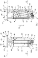
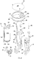
- FIGS. 4 to 9 are views from different points of observation of a filtering unit 1 according to the present invention.
- a filtering unit 1 comprises at least a first module 21 and a second filtering module 22, which form a first filtering stage and a second filtering stage of the water contained in the sludge waste, respectively.
- Unit 1 is further provided with a circulation line 70 configured to transfer the water filtered by the first module 21 to the second module 22.
- the water filtered by the second module 22 is advantageously conveyed into a collection line 80, while the part of water not filtered by the second module 22 is conveyed on a discharge line 81.
- the filtering unit 1 comprises a supporting frame 12 which supports the first module 21 and the second module 22.
- frame 12 is configured so as to be insertable through a manhole 114 of tank 2 for which unit 1 is intended so that, once in use, the filtering modules 21,22 are arranged inside the tank 2.
- manhole 114 indicates a hollow element which is connected, and preferably welded, to the body 2A of tank 2 around an opening 2B defined through the body itself (see figures 1 and 2 ).
- manhole 114 has a circulare section, the extension of which corresponds to that of said opening 2B.
- the hollow part of manhole 114 and the opening 2B make the first compartment 200 communicating with the outside, thus defining a passageway for inserting the frame 12 of unit 1.
- connection means configured to form a connection between frame 12 and tank 2 so that the filtering modules 21, 22 are operatively arranged inside the first compartment 200 upon such a connection.
- such connection means comprise a base 10 from a first side 10A of which the frame 12 develops.
- base 10 is provided with a flange 111 which is connectable, for example through screw/bolt joints, to a corresponding flange 112 fixed to the tank 2, preferably to the end of the manhole 114.
- the two flanges 111,112 are circular flat.
- the two flanges 111,112, like the manhole 114 could also take other shapes.
- Figure 2 refers to the step of inserting unit 1 into tank 2 through the manhole 114.
- the manhole 114 emerges from the upper portion of body 2A so that unit 1 can be inserted/dropped, e.g. by means of a crane or a lift truck, into the tank itself according to a substantially vertically insertion direction.
- the possibility of arranging a manhole 114 in another position, and thus defining another insertion direction, is also within the scope of the present invention.
- the insertion of unit 1 is completed when the two flanges 111,112 come into contact. In this condition, the frame 12 and the two modules 21,22 thus remain in the first compartment 200, i.e. inside the tank 2.
- the connection between the two flanges 111,112 further seals the collected material in the tank 2, thus preventing the sludge from exiting through the manhole 114.
- unit 1 preferably comprises a containment 11 which develops from a second side 10B of the base opposite to the first side 10A from which frame 12 develops.
- the position of containment 11 is opposite to that of the supporting frame 12 with respect to base 10.
- Control means of unit 1 i.e. means configured to control the operation of the modules 21,22 and/or of the operative means arranged along the circulation line 70 and/or along the collection line 80, are preferably located in the containment 11.
- the substantially "outer" position occupied by containment 11 makes the control means advantageously accessible for possible intervention/adjustment operations.
- containment 11 preferably comprises a hollow body 11 A which develops from the mentioned second side 10B of the base 10 and a removable lid 11 B which closes the hollow body 11 A in a position opposite to base 10.
- Hooking means 11 C adapted to promote lifting are preferably provided to remove lid 11 B.
- the collection line 80,80A of the water filtered by the second module 22 advantageously crosses the base 10.
- the water filtered by the first module 21 and by the second module 22 may be advantageously conveyed outside the first compartment 200, e.g. into the second compartment 201 of the tank 2.
- the filtered water may be used for washing operations by exploiting the pressure generated by an appropriate pump according to a principle known in itself.
- a stretch 80A of the collection line 80 crosses containment 11 and a terminal part 80B exits from the containment itself to be connected to a further stretch (not shown), which will be completely outside the tank 2.
- the base 10 preferably develops along a plane 100 and frame 12 prevalently develops along a development direction 101 which is substantially orthogonal to plane 100.
- the frame 12 is preferably extensible/retractable in a reference direction.
- frame 12 is provided with adjustment means which allow to adjust the extension along said reference direction which is preferably parallel to the development direction 101 defined above.
- frame 12 comprises two longitudinal elements 41,42, connected to the first side 10A of base 10, which develop along the development direction 101 as indicated above.
- Frame 12 further comprises two transversal elements 43,44 which develop prevalently along a transversal direction 102 substantially orthogonal to the development direction 101.
- a first transversal element 43 is connected to the two longitudinal elements 41,42 in a position close to base 10
- a second transversal element 44 is connected to the longitudinal elements 41,42 in a position close to a terminal part of the longitudinal elements 41,42 which is opposite to the base 10 itself.
- the longitudinal elements 41,42 comprise a first terminal part 41 A,42A fixed to the first side 10A of base 10 and telescopically inserted into a second part 41B,42B of the element itself.
- the insertion position of the first part 41A,42A in the second part 41B,42B, or vice versa, is established by using screw means 118 or other functionally equivalent means. Such an insertion position thus establishes the extension of the frame 12 along the development direction 101.
- the first module 21 comprises a filtering cartridge 211 and rotation means to rotate cartridge 211 about a rotation axis 150.
- Frame 12 supports the cartridge 211 and the rotation means.
- the first module 21 is supported so that the rotation axis 150 of cartridge 211 is substantially parallel to the development direction 101 of the frame itself. This arrangement contains the overall dimensions of unit 1.
- the filtering cartridge 211 comprises a body with a substantially cylindrical development 211 A defining an inner cavity (not shown in the figures) and some radial passageways. The latter allow the water to pass from the outside towards said inner cavity, while preventing some material from passing.
- Body 211 A is closed at the ends by two containment plates 215A, 215B connected in a rotatable way to corresponding brackets 14A, 14B of frame 12.
- frame 12 comprises a first plate 215A connected rotationally to a first bracket 14A emerging from the first transversal element 43, while a second plate 215B is connected in a rotatable way to a second bracket 14B emerging from the second transversal element 44. As a whole, such rotational connections configure the rotation axis 150 of the filtering cartridge 211.
- the first module 21 also comprises scraper means operatively associated with the filtering cartridge 211 to scrape the outer surface of the body 211 A during the rotation of the cartridge itself.
- scraper means comprise two scraping blades 311 which intervene on the body 211 A in diametrically opposite positions and which are supported at the ends by a corresponding plate 315 adjacent to a corresponding containment plate 215A,215B of cartridge 211.
- the scraping blades 311 are connected to the plates 315 so as to slide according to a substantially radial direction with respect to the rotation axis 150 of cartridge 211.
- Appropriate elastic means act on the scraping blades 311, e.g.
- the rotation means comprise a hydraulic motor 61 connected to one of the containment plates 215A,215B so as to rotate the plate, and the cartridge 211 as a consequence.
- the hydraulic motor 61 is installed in a more distal position from base 10 under the containment plate 215B (see Figure 4 ).
- Such a plate 215B further defines an opening through which the water filtered by cartridge 211 reaches the circulation line 70. Substantially, such an opening defines the outlet of the first module 21 connected to the connection line 70.
- the circulation line 70 comprises a circulation pump 71, actuated by a hydraulic motor 72, the suction of which is connected to the outlet of the first module 21 through a first line stretch 73, preferably in the form of piping.
- the circulation line 70 further comprises a second stretch 74A, 74B which connects the delivery of pump 71 to the second module 22.
- a second stretch 74A, 74B is defined by a piping part 74A and a terminal part 74B of a longitudinal element 41 of the frame 12.
- a hollow portion of a frame element 12 is advantageously exploited as circulation stretch of the water intended to the second module 22.
- the second module 22 comprises at least one cyclone separator, which includes at least one inlet section 22A communicating with the circulation line 70, a first outlet section 22B communicating with the collection line 80 and a second outlet line 22C communicating with the discharge line 81.
- the cyclone separator has a conformation known in itself defined by a substantially cylindrical portion 25 in which the water enters according to a tangential direction to take a spiral (swirling) motion in the chamber itself.
- the chamber 25 defines the first outlet section 22B connected to the connection line.
- the cyclone separator further comprises a conical portion 26 underneath and communicating with the cylindrical one.
- the second module 22 comprises a plurality of cyclone separators each with the features described above.
- each cyclone separator is connected to the part 74A of the circulation line 70 through a connection stretch 75, e.g. flexible.
- the first outlet section 22B of each cyclone is communicating with a rectilinear stretch 88 of the collection line 80 inclined with respect to the development direction 101.
- the second outlet section 22C of each cyclone also communicates with a rectilinear stretch 81 A of the discharge line 81, which is substantially parallel to the mentioned stretch 88 of the collection line 80.
- the cyclone separators of the second filtering module 22 are preferably arranged on one side of the supporting frame 12 opposite to the that which supports the first module 21.
- the discharge line 81 of the water not filtered by the second module 22 has a further stretch 81 B, which is substantially parallel to the development direction 101 of the frame. Such a stretch 81 B is downstream of the inclined stretch 81 A with respect to the flow of water not filtered by the second module 22.
- unit 1 comprises anchoring means for stably anchoring frame 12 into the compartment 200 once unit 1 is inserted into the tank itself. More specifically, such anchoring means allow to fix frame 12 in a stable manner to one or more brackets 35 (or supports) fixed inside tank 2, e.g. by welding. In a possible embodiment shown in Figures 6 and 7 , the brackets 35 are fixed to the inner surface of tank 2 in a position substantially opposite to the opening of the manhole 114 through which frame 12 is inserted. Thereby, at least two anchoring points are generated in a position opposite to the base 10 fixed to tank 2.
- the connection means may comprise screw elements or functionally equivalent elements through which the longitudinal elements 41,42 are fixed to the brackets 35.
- the control means of unit 1 comprise a controller 300 and a hydraulic assembly 315 operatively connected to the hydraulic motors 61,72 which actuate pump 71 and the rotation of the cartridge 211 of the first module 21, respectively.
- unit 1 comprises a feeding line 98 and a return line 99 of the oil for each hydraulic motor 61,72.
- the hydraulic assembly 315 handles the oil flow through said lines 98,99 and for this purpose comprises solenoid valves (not shown), the activation of which is adjusted by controller 300.
- controller 300 sends the control signals to the hydraulic assembly 315, upon which the pump 71 and/or the hydraulic motor 61 of the first module 21 is activated/deactivated.
- the hydraulic assembly 315 is configured to manage the operation of pump 71 with either fixed displacement or variable displacement.
- unit 1 comprises signaling means 350 elastically connected to controller 300 to indicate the operative states and/or possible operating abnormalities of the filtering modules 21,22.
- the signaling means 350 e.g. warning lights, are preferably installed on the body 11 A of containment 11 so as to be visible from the ground.
- control means comprise pressure sensor means 77 associated with the hydraulic assembly 315 arranged within the containment 11.
- sensor means 77 detect the oil pressure along the feeding line 98 of the hydraulic motor 72 which actuates pump 71. Such a pressure is indicative of the water flow rate processed by the pump itself.
- a pressure line lower than a predetermined value indicates a substantially no-load operation of pump 71, and thus the absence of water in compartment 200. The presence/absence of water in compartment 200 is thus monitored by means of sensor means 77 which remain outside the compartment itself, as it is housed in containment 11.
- the sensor means 77 are electrically connected to the controller 300 which intervenes on the hydraulic assembly 315 as a function of the received pressure signal.
- controller 300 sends a control signal to the hydraulic assembly, upon which the hydraulic motor 61 of the first module 21 and the hydraulic motor 72 of pump 71 are activated.
- the pressure detected by the sensor means 77 is higher than a predetermined reference value, the two hydraulic motors 61,72 are maintained in the activated state. Instead, when the pressure is the lower than the reference value, the control 300 sends another control signal to the hydraulic assembly 315 after which the two hydraulic motors 61 and 72 are deactivated.
- the signaling means 350 shown above are configured so as to indicate the operative states (activation and deactivation) at least of the first filtering module 21 and/or of the pump 71.
- controller 300 can be performed remotely or alternatively even by exploiting discreet connections with CAN BUS protocol.
- the electrical power supply of controller 300 is preferably derived from the vehicle which supports the tank itself. In fixed applications, the power supply may be obtained by means of autonomous batteries.
- an ON-OFF valve is provided along the water collection line 80, preferably in the stretch crossing container 11.
- the purpose of such a valve is to allow the water to pass in the open (ON) position or to prevent it in the closed (OFF) position.
- the ON-OFF valve is also controlled by means of a solenoid valve controlled by controller 300.
- controller 300 sends an activation or deactivation signal after which the valve is selectively opened or closed.
- controller 300 sends an activation control of the ON-OFF valve after a predetermined period of time from the activation of the hydraulic motor 61 which activates the first module 21.
- control unit which comprises at least the steps of:
- the rotary filter of the first module 21, in combination with the second module 22, comprises three cyclone separators to obtain a continuous variable filtering from 100 to 500 liters/minutes with filtering level from 30 to 50 microns.
- the present invention further relates to equipment, preferably in the form of a tank truck, for collecting and treating sludge waste comprising a part of water, where said equipment comprises at least one tank 2 defining a compartment 200 for collecting said waste and at least one the manhole 114 defining a passageway for inserting filtering means into compartment 200.
- the equipment according to the invention is thus characterized in that the filtering means comprise a filtering unit 1 with the technical features and peculiarities described above.
- unit 1 may also be inserted into a tank 2 in which the sludge collection compartment has an adjustable extension.
- the manhole 114 will be arranged in an appropriate position or alternatively a plurality of the manholes will be present.
- the manufacturing and assembly cost for a piece of equipment, in particular a tank truck will be advantageously lower than the solutions known from the prior art.
Landscapes
- Chemical & Material Sciences (AREA)
- Engineering & Computer Science (AREA)
- Chemical Kinetics & Catalysis (AREA)
- Mechanical Engineering (AREA)
- Life Sciences & Earth Sciences (AREA)
- Hydrology & Water Resources (AREA)
- Environmental & Geological Engineering (AREA)
- Water Supply & Treatment (AREA)
- Organic Chemistry (AREA)
- Filtration Of Liquid (AREA)
Priority Applications (4)
| Application Number | Priority Date | Filing Date | Title |
|---|---|---|---|
| EP16192868.4A EP3305733A1 (fr) | 2016-10-07 | 2016-10-07 | Unité de filtration pour la collecte de déchets et/ou équipement de traitement |
| ES17791955T ES3034253T3 (en) | 2016-10-07 | 2017-10-09 | Equipment for collecting and treating waste with a filtering unit and process therefor |
| EP17791955.2A EP3523256B1 (fr) | 2016-10-07 | 2017-10-09 | Équipement et procédé pour la collecte et le traitement de déchets, avec une unité de filtration |
| PCT/EP2017/075691 WO2018065630A1 (fr) | 2016-10-07 | 2017-10-09 | Unité de filtrage destinée à un équipement de collecte et de traitement de déchets, équipement de collecte et de traitement de déchets et procédé de collecte et de traitement de déchets |
Applications Claiming Priority (1)
| Application Number | Priority Date | Filing Date | Title |
|---|---|---|---|
| EP16192868.4A EP3305733A1 (fr) | 2016-10-07 | 2016-10-07 | Unité de filtration pour la collecte de déchets et/ou équipement de traitement |
Publications (1)
| Publication Number | Publication Date |
|---|---|
| EP3305733A1 true EP3305733A1 (fr) | 2018-04-11 |
Family
ID=57421611
Family Applications (2)
| Application Number | Title | Priority Date | Filing Date |
|---|---|---|---|
| EP16192868.4A Withdrawn EP3305733A1 (fr) | 2016-10-07 | 2016-10-07 | Unité de filtration pour la collecte de déchets et/ou équipement de traitement |
| EP17791955.2A Active EP3523256B1 (fr) | 2016-10-07 | 2017-10-09 | Équipement et procédé pour la collecte et le traitement de déchets, avec une unité de filtration |
Family Applications After (1)
| Application Number | Title | Priority Date | Filing Date |
|---|---|---|---|
| EP17791955.2A Active EP3523256B1 (fr) | 2016-10-07 | 2017-10-09 | Équipement et procédé pour la collecte et le traitement de déchets, avec une unité de filtration |
Country Status (3)
| Country | Link |
|---|---|
| EP (2) | EP3305733A1 (fr) |
| ES (1) | ES3034253T3 (fr) |
| WO (1) | WO2018065630A1 (fr) |
Cited By (1)
| Publication number | Priority date | Publication date | Assignee | Title |
|---|---|---|---|---|
| CN111330345A (zh) * | 2020-03-03 | 2020-06-26 | 湖南文理学院 | 一种基于医药化工的中药内部成分提取用固液分离机 |
Families Citing this family (2)
| Publication number | Priority date | Publication date | Assignee | Title |
|---|---|---|---|---|
| CN108483817B (zh) * | 2018-05-17 | 2021-02-26 | 威海云之卫智能科技有限公司 | 一种基于工业污水再利用的深度处理过滤系统 |
| CN115193119B (zh) * | 2022-05-20 | 2023-09-19 | 江阴中弘建设有限公司 | 市政生活污水环保处理系统 |
Citations (4)
| Publication number | Priority date | Publication date | Assignee | Title |
|---|---|---|---|---|
| GB2107598A (en) * | 1981-10-06 | 1983-05-05 | Bill Blake Trautwein | Cooling tower basin water treating apparatus and methods |
| US5435854A (en) * | 1990-08-10 | 1995-07-25 | Pipeline Sewer Services, Inc. | Pipe cleaning modules and systems and methods for their use |
| DE202004011107U1 (de) * | 2004-07-13 | 2004-10-07 | Ffg Flensburger Fahrzeugbau Gesellschaft Mbh | Vorrichtung zum Abscheiden von Wasser aus Spülschlamm |
| US20160121248A1 (en) * | 2012-01-16 | 2016-05-05 | Jk Industries, Llc | Sludge concentrator assembly with varying first stage separator, combined with a second stage, clean flow outlet incorporating fixed and variable flow restrictor orifices |
Family Cites Families (3)
| Publication number | Priority date | Publication date | Assignee | Title |
|---|---|---|---|---|
| KR100618919B1 (ko) * | 2006-05-23 | 2006-09-01 | (주)신정뉴테크 | 이동형 하수도 준설토 일괄 처리장치 |
| KR100674138B1 (ko) * | 2006-08-21 | 2007-01-29 | 한국전력공사 | 맨홀 청소차의 물재사용 오수 처리 장치 |
| US7731840B1 (en) * | 2009-09-18 | 2010-06-08 | Green Intellectual Properties, Llc | Apparatus for removing hydrocarbons and contaminates |
-
2016
- 2016-10-07 EP EP16192868.4A patent/EP3305733A1/fr not_active Withdrawn
-
2017
- 2017-10-09 ES ES17791955T patent/ES3034253T3/es active Active
- 2017-10-09 WO PCT/EP2017/075691 patent/WO2018065630A1/fr not_active Ceased
- 2017-10-09 EP EP17791955.2A patent/EP3523256B1/fr active Active
Patent Citations (4)
| Publication number | Priority date | Publication date | Assignee | Title |
|---|---|---|---|---|
| GB2107598A (en) * | 1981-10-06 | 1983-05-05 | Bill Blake Trautwein | Cooling tower basin water treating apparatus and methods |
| US5435854A (en) * | 1990-08-10 | 1995-07-25 | Pipeline Sewer Services, Inc. | Pipe cleaning modules and systems and methods for their use |
| DE202004011107U1 (de) * | 2004-07-13 | 2004-10-07 | Ffg Flensburger Fahrzeugbau Gesellschaft Mbh | Vorrichtung zum Abscheiden von Wasser aus Spülschlamm |
| US20160121248A1 (en) * | 2012-01-16 | 2016-05-05 | Jk Industries, Llc | Sludge concentrator assembly with varying first stage separator, combined with a second stage, clean flow outlet incorporating fixed and variable flow restrictor orifices |
Cited By (1)
| Publication number | Priority date | Publication date | Assignee | Title |
|---|---|---|---|---|
| CN111330345A (zh) * | 2020-03-03 | 2020-06-26 | 湖南文理学院 | 一种基于医药化工的中药内部成分提取用固液分离机 |
Also Published As
| Publication number | Publication date |
|---|---|
| ES3034253T3 (en) | 2025-08-14 |
| EP3523256B1 (fr) | 2025-05-28 |
| WO2018065630A1 (fr) | 2018-04-12 |
| EP3523256A1 (fr) | 2019-08-14 |
| EP3523256C0 (fr) | 2025-05-28 |
Similar Documents
| Publication | Publication Date | Title |
|---|---|---|
| US5372722A (en) | Oil separator with integrated microfiltration device | |
| US20060081543A1 (en) | Liquid/solid separator and method | |
| KR20110119686A (ko) | 슬러지 탈수 및 건조 | |
| CN101309871A (zh) | 垃圾车的水回用污水处理设备 | |
| CN115738475B (zh) | 一种磨削液过滤净化装置、三相分离系统及清洗结构 | |
| KR102118685B1 (ko) | 고압용 오배수 펌프시스템 | |
| EP3523256B1 (fr) | Équipement et procédé pour la collecte et le traitement de déchets, avec une unité de filtration | |
| CN101433784A (zh) | 免拆卸泵前过滤装置 | |
| EP2192967B1 (fr) | Equipement de filtration autonettoyant équipé d'un filtre à tambour rotatif pour liquides pollués | |
| KR20140031188A (ko) | 펌프 장치 | |
| EP0906877B1 (fr) | Accumulateur à vide raccordé à une tubulure d'aspiration | |
| CN208603907U (zh) | 一种废水处理装置 | |
| CN107030075A (zh) | 一种自动收集废渣的水污分离系统 | |
| CN106395981A (zh) | 一种适用于舰船的污油水分离装置 | |
| CN218794230U (zh) | 太阳能水力自清洗过滤器 | |
| KR20180056279A (ko) | 무차단 자동 스트레이너 | |
| AU2008318264B2 (en) | Fuel and fuel tank treatment | |
| WO2020021355A1 (fr) | Système et procédé de traitement d'eau pour un agencement de lavage de roues | |
| JP2007007618A (ja) | 高汚濁水用の浄水処理方法及び装置 | |
| US20210101803A1 (en) | Portable fluid collection and filtration system | |
| JP3169267U (ja) | 汚水浄化装置 | |
| CN209076177U (zh) | 一种带溢流结构固液分离装置 | |
| HK40039787A (en) | Floor cleaning machine | |
| CN215365001U (zh) | 一种自动排油油水分离器 | |
| CN112678982B (zh) | 一种用于处理餐饮废水的除油除渣设备 |
Legal Events
| Date | Code | Title | Description |
|---|---|---|---|
| PUAI | Public reference made under article 153(3) epc to a published international application that has entered the european phase |
Free format text: ORIGINAL CODE: 0009012 |
|
| AK | Designated contracting states |
Kind code of ref document: A1 Designated state(s): AL AT BE BG CH CY CZ DE DK EE ES FI FR GB GR HR HU IE IS IT LI LT LU LV MC MK MT NL NO PL PT RO RS SE SI SK SM TR |
|
| AX | Request for extension of the european patent |
Extension state: BA ME |
|
| STAA | Information on the status of an ep patent application or granted ep patent |
Free format text: STATUS: THE APPLICATION IS DEEMED TO BE WITHDRAWN |
|
| 18D | Application deemed to be withdrawn |
Effective date: 20181012 |