EP3305964A1 - Machine à laver - Google Patents
Machine à laver Download PDFInfo
- Publication number
- EP3305964A1 EP3305964A1 EP16799323.7A EP16799323A EP3305964A1 EP 3305964 A1 EP3305964 A1 EP 3305964A1 EP 16799323 A EP16799323 A EP 16799323A EP 3305964 A1 EP3305964 A1 EP 3305964A1
- Authority
- EP
- European Patent Office
- Prior art keywords
- washing
- drum
- washing drum
- washing machine
- circumferential surface
- Prior art date
- Legal status (The legal status is an assumption and is not a legal conclusion. Google has not performed a legal analysis and makes no representation as to the accuracy of the status listed.)
- Withdrawn
Links
- 238000005406 washing Methods 0.000 title claims abstract description 272
- 238000003756 stirring Methods 0.000 claims abstract description 13
- XLYOFNOQVPJJNP-UHFFFAOYSA-N water Substances O XLYOFNOQVPJJNP-UHFFFAOYSA-N 0.000 claims description 66
- 239000011521 glass Substances 0.000 claims description 23
- 239000000463 material Substances 0.000 claims description 23
- 238000007789 sealing Methods 0.000 claims description 20
- 230000002159 abnormal effect Effects 0.000 abstract description 7
- 238000011282 treatment Methods 0.000 description 9
- 239000000725 suspension Substances 0.000 description 7
- 238000004140 cleaning Methods 0.000 description 5
- 239000003599 detergent Substances 0.000 description 4
- 238000009434 installation Methods 0.000 description 4
- 239000012535 impurity Substances 0.000 description 3
- 238000003780 insertion Methods 0.000 description 3
- 230000037431 insertion Effects 0.000 description 3
- 238000004519 manufacturing process Methods 0.000 description 3
- 239000002202 Polyethylene glycol Substances 0.000 description 2
- 230000003213 activating effect Effects 0.000 description 2
- 238000000034 method Methods 0.000 description 2
- 229920001223 polyethylene glycol Polymers 0.000 description 2
- 239000011347 resin Substances 0.000 description 2
- 229920005989 resin Polymers 0.000 description 2
- 239000000126 substance Substances 0.000 description 2
- 241000276425 Xiphophorus maculatus Species 0.000 description 1
- 238000011161 development Methods 0.000 description 1
- 230000018109 developmental process Effects 0.000 description 1
- 230000009977 dual effect Effects 0.000 description 1
- 230000000694 effects Effects 0.000 description 1
- 239000012530 fluid Substances 0.000 description 1
- 125000005487 naphthalate group Chemical group 0.000 description 1
- 235000016709 nutrition Nutrition 0.000 description 1
- 239000004417 polycarbonate Substances 0.000 description 1
- 229920000515 polycarbonate Polymers 0.000 description 1
- 238000011160 research Methods 0.000 description 1
- KKEYFWRCBNTPAC-UHFFFAOYSA-L terephthalate(2-) Chemical compound [O-]C(=O)C1=CC=C(C([O-])=O)C=C1 KKEYFWRCBNTPAC-UHFFFAOYSA-L 0.000 description 1
Images

Classifications
-
- D—TEXTILES; PAPER
- D06—TREATMENT OF TEXTILES OR THE LIKE; LAUNDERING; FLEXIBLE MATERIALS NOT OTHERWISE PROVIDED FOR
- D06F—LAUNDERING, DRYING, IRONING, PRESSING OR FOLDING TEXTILE ARTICLES
- D06F37/00—Details specific to washing machines covered by groups D06F21/00 - D06F25/00
- D06F37/02—Rotary receptacles, e.g. drums
- D06F37/12—Rotary receptacles, e.g. drums adapted for rotation or oscillation about a vertical axis
- D06F37/14—Ribs or rubbing means forming part of the receptacle
-
- D—TEXTILES; PAPER
- D06—TREATMENT OF TEXTILES OR THE LIKE; LAUNDERING; FLEXIBLE MATERIALS NOT OTHERWISE PROVIDED FOR
- D06F—LAUNDERING, DRYING, IRONING, PRESSING OR FOLDING TEXTILE ARTICLES
- D06F23/00—Washing machines with receptacles, e.g. perforated, having a rotary movement, e.g. oscillatory movement, the receptacle serving both for washing and for centrifugally separating water from the laundry
- D06F23/04—Washing machines with receptacles, e.g. perforated, having a rotary movement, e.g. oscillatory movement, the receptacle serving both for washing and for centrifugally separating water from the laundry and rotating or oscillating about a vertical axis
-
- D—TEXTILES; PAPER
- D06—TREATMENT OF TEXTILES OR THE LIKE; LAUNDERING; FLEXIBLE MATERIALS NOT OTHERWISE PROVIDED FOR
- D06F—LAUNDERING, DRYING, IRONING, PRESSING OR FOLDING TEXTILE ARTICLES
- D06F37/00—Details specific to washing machines covered by groups D06F21/00 - D06F25/00
- D06F37/02—Rotary receptacles, e.g. drums
- D06F37/12—Rotary receptacles, e.g. drums adapted for rotation or oscillation about a vertical axis
- D06F37/14—Ribs or rubbing means forming part of the receptacle
- D06F37/145—Ribs or rubbing means forming part of the receptacle ribs or lifters having means for circulating the washing liquid
-
- D—TEXTILES; PAPER
- D06—TREATMENT OF TEXTILES OR THE LIKE; LAUNDERING; FLEXIBLE MATERIALS NOT OTHERWISE PROVIDED FOR
- D06F—LAUNDERING, DRYING, IRONING, PRESSING OR FOLDING TEXTILE ARTICLES
- D06F37/00—Details specific to washing machines covered by groups D06F21/00 - D06F25/00
- D06F37/20—Mountings, e.g. resilient mountings, for the rotary receptacle, motor, tub or casing; Preventing or damping vibrations
- D06F37/24—Mountings, e.g. resilient mountings, for the rotary receptacle, motor, tub or casing; Preventing or damping vibrations in machines with a receptacle rotating or oscillating about a vertical axis
-
- D—TEXTILES; PAPER
- D06—TREATMENT OF TEXTILES OR THE LIKE; LAUNDERING; FLEXIBLE MATERIALS NOT OTHERWISE PROVIDED FOR
- D06F—LAUNDERING, DRYING, IRONING, PRESSING OR FOLDING TEXTILE ARTICLES
- D06F37/00—Details specific to washing machines covered by groups D06F21/00 - D06F25/00
- D06F37/26—Casings; Tubs
- D06F37/266—Gaskets mounted between tub and casing around the loading opening
-
- D—TEXTILES; PAPER
- D06—TREATMENT OF TEXTILES OR THE LIKE; LAUNDERING; FLEXIBLE MATERIALS NOT OTHERWISE PROVIDED FOR
- D06F—LAUNDERING, DRYING, IRONING, PRESSING OR FOLDING TEXTILE ARTICLES
- D06F37/00—Details specific to washing machines covered by groups D06F21/00 - D06F25/00
- D06F37/30—Driving arrangements
- D06F37/40—Driving arrangements for driving the receptacle and an agitator or impeller, e.g. alternatively
-
- D—TEXTILES; PAPER
- D06—TREATMENT OF TEXTILES OR THE LIKE; LAUNDERING; FLEXIBLE MATERIALS NOT OTHERWISE PROVIDED FOR
- D06F—LAUNDERING, DRYING, IRONING, PRESSING OR FOLDING TEXTILE ARTICLES
- D06F39/00—Details of washing machines not specific to a single type of machines covered by groups D06F9/00 - D06F27/00
- D06F39/12—Casings; Tubs
Definitions
- the present invention relates to a washing machine capable of not only simply and reliably removing stains on an inner and outer circumferential surface of a washing drum, but also greatly increasing the assembling efficiency and the space efficiency by reducing the common used components, thereby further reducing abnormal noise.
- An existing vertical washing machine includes: a main body frame forming a housing of the washing machine; an outer drum disposed inside the main body frame and storing washing fluid; a dewatering drum disposed inside the outer drum in a freely rotating manner and having an impeller at a bottom; and a suspension rod for suspending the outer drum relative to the main body frame (for example the patent document 1). Washings are thrown into the dewatering drum of the washing machine, the dewatering drum can rotate to perform washing treatment while washing water is stored in the outer drum, and to perform dewatering treatment while the washing water is discharged. When performing the treatments, the outer drum and the main body frame obtain a balance by utilizing the suspension rod, and thus can be prevented from being contacted each other, thereby reducing the noise.
- Patent document 1 Japanese Laid-Open Patent Publication No. 2004-275480
- the outer circumferential surface of the dewatering drum is in a state of being dipped in the washing water containing stains and detergent impurities attached to the washings. Since part of the stains and detergent impurities may still remain on the outer circumferential surface of the dewatering drum after the dewatering treatment and may be gradually accumulated, molds (mainly black molds) using the remaining stains and the detergent impurities as a nutritional source may be generated on the outer circumferential surface of the dewatering drum.
- the existing washing machine is a structure in which a hand cannot enter between the dewatering drum and the outer drum.
- the dewatering drum is connected with an electric motor serving as a driving unit and difficult to be removed from a washing machine body. Therefore, in the existing washing machine, it is difficult for a user to wash directly the drum such as cleaning of stains on the outer circumferential surface of the dewatering drum.
- the stains and molds on the outer circumferential surface of the dewatering drum can be removed by virtue of chemical methods such as utilizing the drum cleaning detergent, compared with the direct drum cleaning treatment, the chemical methods have a problem of a stain removal rate.
- the existing washing machine is considered to have the following problems, i.e., since the existing washing machine further has a suspension rod for suspending the outer drum besides a three-layer structure having the main body frame, the outer drum and the dewatering drum, the quantity of components is increased, and the assembling time during manufacture is difficult to shorten. Additionally, an invalid space is formed between the main body frame and the outer drum, and the washing capacity (the capacity of the dewatering drum) can be greatly reduced relative to the volume of the main body frame, so it is hardly to be the high space efficiency. Further, when the dewatering is activated, the outer drum suspended by the suspension rod may contact the main body frame, thereby generating abnormal noise.
- the present invention aims at effectively solving the problems described above, and specifically aims at providing a washing machine which can simply and reliably remove stains on the outer circumferential surface of the washing drum forming the dewatering drum and greatly increase the assembling efficiency and the space efficiency by reducing the common used components, and does not generate the abnormal noise caused by the contact of components when the dewatering is activated.
- the present invention adopts the following solution.
- the washing machine of the present invention includes a closed bottomed cylindrical first washing drum forming a housing of a washing machine body and has an upper opening; a closed bottomed cylindrical second washing drum disposed in a specified distance from an inner circumferential surface of the first washing drum and the first washing drum in a freely rotating manner and serving as a dewatering drum; a circular plate portion having stirring wings extending radially outwardly of the second washing drum and integrally formed with the second washing drum; and an electric motor for driving the second washing drum and the circular plate portion to rotate together.
- At least one portion of the first washing drum is formed by a transparent member.
- a side wall of the first washing drum is particularly preferably formed by a plurality of transparent glass materials connected by water sealing portions in a circumferential direction.
- At least any one of the inner circumferential surface of the first washing drum and the outer circumferential surface of the second washing drum is further preferably provided with lifting ribs.
- the washings can be thrown between the first washing drum and the second washing drum and into the second washing drum.
- the electric motor can be activated in a state that the first washing drum is fully filled with water to rotate the second washing drum and the circular plate portion and to generate a water flow in the first washing drum through the stirring wings, thereby cleaning the washings.
- the second washing drum is rotated while the water is discharged, thereby centrifugally dewatering the washings.
- the washing machine of the present invention is not only a novel structure that is not provided to date, but also can perform appropriate washing operation.
- the first washing drum also functions as the main body frame and the outer drum of the existing washing machine
- the second washing drum also serves as the dewatering drum
- the second washing drum is integrally formed with the circular plate portion. Therefore, it is possible to achieve a double-layer structure that the second washing drum is configured in the first washing drum, without the needs of arranging a three-layer structure like the existing washing machine or suspending the components by using the suspension rod.
- the washing machine of the present invention can reduce the common used components and an invalid space in the washing machine body, can greatly increase the assembling efficiency and the space efficiency during manufacture, and can eliminate the abnormal noise caused by the contact of the components when activating the dewatering.
- the user can clearly confirmed the states of the stain on the inner circumferential surface of the first washing drum and the outer circumferential surface of the second washing drum from the outside of the washing machine body, so that the user can simply and appropriately determine when to clean the washing drum according to his/her own judgment.
- the side wall of the first washing drum is formed by a plurality of transparent glass materials, compared with a situation that the first washing drum is formed by, for example, resin, the stains are difficult to attach, and the washings are difficult to damage even if the washings are rubbed during the washing treatment.
- the first washing drum with a great diameter can be manufactured by connecting the plurality of transparent glass materials through the water sealing portions, without particular customization, achieving the washing machine with low cost and large one-time washing capacity.
- the washings in the first washing drum are rubbed by the lifting ribs, increasing the washing force.
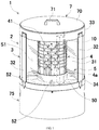
- Fig. 1 is a perspective view illustrating an appearance of a vertical washing machine 1 (hereinafter called “washing machine") according to embodiments of the present invention.
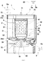
- Fig. 2 is a longitudinal section view illustrating the washing machine 1.
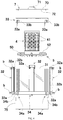
- Fig. 3 is an exploded perspective view illustrating the washing machine 1.
- Fig. 4 is an exploded side view illustrating the washing machine 1.
- the washing machine 1 includes a washing machine body 2, an upper cover 7, a water supply unit 8, a water discharge unit 9 and a control unit 65.
- a top surface of such the washing machine 1 is provided with a control board (not shown) having an operation start button for example.
- the water supply unit 8, the water discharge unit 9 and the control unit 65 are not shown in Figs. 1 , 3 and 4 .
- the washing machine body 2 has a first washing drum 3, a second washing drum 4, a circular plate portion 5, a driving unit 6, and a foot box 75.
- the first washing drum 3 has a closed bottomed cylindrical shape with an upper opening, can store water therein, and can form the housing of the washing machine body 2 as shown in Fig. 1 .
- the first washing drum 3 is configured in such a way that a first accommodating space S1 is formed between the first washing drum 3 and the second washing drum 4, in which the washings can be stored when opening the upper cover 7. A detailed structure of the first washing drum 3 is described later.
- the second washing drum 4 has a closed bottomed cylindrical shape and is formed in such a manner that a length in an axial direction and a diameter are smaller than those of the first washing drum 3.
- the diameter of the second washing drum 4 is configured to be about one third to half of the diameter of the first washing drum 3.
- the length of the second washing drum 4 in the axial direction is configured to be about half to four fifths of the length of the first washing drum 3 in the axis direction.
- the second washing drum 4 inside the first washing drum 3 is configured on a concentric circle of the first washing drum 3 in a freely rotating manner at a specified interval from an inner circumferential surface of the first washing drum 3.
- the second washing drum 4 is configured in such a way that a second accommodating space S2 (as shown in Fig. 2 ) capable of accommodating the washings is formed inside the second washing drum 4 in which the washings can be stored and fetched when opening the upper cover 7.
- the second washing drum 4 also serves as a dewatering drum, and a plurality of water through holes 41 are disposed at its side wall. Therefore, when the second washing drum 4 rotates in a state of accommodating the wetted washings, the washings are centrifugally dewatered, and then the water flows out of the second washing drum 4 via the water through holes 41.
- the circular plate portion (impeller) 5 is integrally formed with the second washing drum 4, and has an approximately circular-plate-shaped circular plate portion body 50 extending radially outwardly from a bottom 4a of the second washing drum 4 and a plurality of (4 in the present embodiment) stirring wings 52 formed on the top surface of the circular plate portion body 50.
- the stirring wings 52 extend radially outwardly of the second washing drum 4 from the bottom 4a of the second washing drum 4 to the outer circumferential end portion of the circular plate portion body 50, and are disposed in a circumferential direction of the circular plate portion body 50 at equal intervals.
- the stirring wings 52 stir the water stored in the first washing drum 3 through the water supply unit 8 shown in Fig. 2 so as to generate a water flow.
- an outer side portion of the impeller located on the radial outer side has a greater force for stirring the water and the washings, and contributes more to wash the washings.
- the circular plate portion 5 of the washing machine 1 is only formed by a portion corresponding to the outer side portion of the existing impeller. The washing machine 1 generates a strong water flow in the first accommodating space S1 and can contribute a washing force which is as high as the existing washing machine.
- the driving unit 6 shown in Fig. 2 includes an electric motor 61, and is configured below the first washing drum 3 and the second washing drum 4.
- the electric motor 61 rotates a driving shaft 60 extending and protruding towards the bottom 4a of the second washing drum 4, rotates the second washing drum 4 and the circular plate portion 5 integrally at a high speed, and applies a driving force that rotates the washings and water accommodated in the first washing drum 3 and the second washing drum 4.
- a direct driving motor (DDM) is used as the electric motor 61.
- An operation of the driving unit 6 is controlled by the control unit 65 adopting an inverter.
- the control unit 65 also outputs control signals Sa and Sb to control the water supply of the water supply unit 8 and the water discharge of the water discharge unit 9, respectively.
- the foot box 75 is a cylindrical member having a diameter identical with the first washing drum 3, and an upper end portion of the foot box is fixed to a washing drum bottom 34 described below.
- the foot box 75 functions as a foot of the washing machine 1.
- the above driving unit 6 is accommodated in the foot box 75.
- the upper cover 7 can be opened and closed relative to the washing machine body 2, as shown in Fig. 3 .
- the upper cover 7 has a substantially circular plate shaped cover body 70, and a handrail portion 71 installed on a central portion of the top surface of the cover main body 70.
- an overhang portion 72 extending downwards from an edge portion of the cover main body 70 contacts the inner circumferential surface of a top panel 33 described below, and the opening of the washing machine body 2 can be closed as shown in Fig. 1 .
- the closed bottomed cylindrical second washing drum 4 serving as the dewatering drum is configured in the closed bottomed cylindrical first washing drum 3 forming the housing of the washing machine body 2 in a freely rotating manner.
- the second washing drum 4 is integrally formed with the circular plate portion 5 with stirring wings 52 extending radially outwardly from the bottom portion 4a of the second washing drum 4, and is driven to rotate together with the circular plate portion 5 by the electric motor 61.
- the user can throw the washings into the first accommodating space S1 formed between the first washing drum 3 and the second washing drum 4 and the second accommodating space S2 formed inside the second washing drum 4, can activate the electric motor 61 in a state that the first washing drum 3 is fully filled with water to rotate the second washing drum 4 and the circular plate portion 5 and to generate a water flow in the first washing drum 3 through the stirring wings 52, thereby cleaning the washings.
- the second washing drum 4 can be rotated while the water is discharged, thereby centrifugally dewatering the washings.
- the washing machine 1 of the present embodiment is not only a novel structure that is not provided to date as shown in Fig. 1 , but also can perform the appropriate washing treatment. It can allow a hand to enter the first washing drum 3 from the upper side so as to directly clean the inner circumferential surface of the first washing drum 3 and the outer circumferential surface of the second washing drum, thereby simply and reliably removing stains and molds on the outer circumferential surface of the second washing drum serving as the dewatering drum.
- the first washing drum 3 functions as the main body frame and the outer drum of the existing washing machine
- the second washing drum 4 also serves as the dewatering drum
- the second washing drum 4 is integrally formed with the circular plate portion 5. Therefore, it is possible to achieve a double-layer structure that the second washing drum 4 is configured in the first washing drum 3, without the needs of arranging a three-layer structure like the existing washing machine or suspending the components by using the suspension rod.
- the second washing drum 4 and the circular plate portion 5 can be driven to rotate by one electric motor 61. Therefore, the washing machine 1 can reduce the common used components and the invalid space in the washing machine body 2, can greatly increase the assembling efficiency and the space efficiency during manufacture, and can eliminate the abnormal noise caused by the contact of the components when activating the dewatering.
- the water flow generated in the second accommodating space S2 inside the second washing drum 4 is weaker than the water flow generated in the first accommodating space S1
- the clothes, such as thin clothes, easy to damage can also be thrown into the second accommodating space S2to be washed separately. That is, the second washing drum 4 capable of generating a water flow different from a water flow in the first washing drum 3 can be used as a separately washing drum.
- the first washing drum 3 is formed by the following portions, i.e., transparent glass materials 31 serving as a plurality of (3 in the present embodiment) transparent members, a plurality of (3 in the present embodiment) water sealing portions (columns) 32 for connecting the transparent glass materials 31, a cylindrical top panel 33 installed on the upper ends of the transparent glass materials 31 and the water sealing portions 32, and the washing drum bottom 34.
- the user can clearly confirm the state of the stain on the inner circumferential surface of the first washing drum 3 and the outer circumferential surface of the second washing drum 4 from the outer side of the washing machine body 2, so that the user can simply and appropriately determine when to clean the washing drums 3 and 4 according to his/her own judgment.
- the user can simply confirm the detachment of the stains.
- a situation (state) of the washings being washed can be confirmed from the outside of the washing machine body 2, the user can adjust a water level when the washings are washed, and can confirm the turbidity of the water when the washings are rinsed.
- the transparent glass materials 31 are in a shape of a substantially rectangle bent leftwards and rightwards into an arc shape in a cross section direction.
- a gasket 31a two ends in the left-right direction and a lower end are covered by a gasket 31a.
- the water sealing portion 32 is a platy member with an up-down size longer than an up-down size of the transparent glass materials 31.
- An enlarged concave portion 32b shown in Fig. 3 is formed at both ends of the water sealing portion 32 in the left-right direction.
- the end portions in the left-right direction of the transparent glass materials 31 covered by the gasket 31a are inserted into the concave portions 32b.
- insertion holes 32a through which a fastener b such as a screw passes are formed in both ends in the up-down direction of the water sealing portion 32.
- An upper end of the water sealing portion 32 is fixed to the top panel 33, and a lower end of the water sealing portion 32 is fixed to the washing drum bottom 34.
- the top panel 33 is configured to be a cylindrical member in such a way that the concave portion 33c (referring to Fig. 2 ) is formed on a lower end surface for inserting the upper end portion of the transparent glass materials 31 therein.
- a plurality of (3 in the present embodiment) installation concave portions 33a facing downwards are formed at equal intervals in the circumferential direction.
- Fastening holes 33b such as threaded holes are formed in each installation concave portion 33a.
- the fasteners b pass through the insertion holes 32a and the fastening holes 33b so that the water sealing portion 32 is fixed to the top panel 33.
- the above transparent glass materials 31, the water sealing portions 32 and the top panel 33 form a side wall of the first washing drum 3.
- the washing drum bottom 34 has a substantially bowl shape with a central portion sunken into a circular shape.
- a concave portion 34d (referring to Fig. 2 ) is formed in the upper end surface of the washing drum bottom 34 for inserting the lower end portion of the transparent glass materials 31 therein.
- fastening portions 34a are formed on the outer side surface of the washing drum bottom 34 corresponding to the installation concave portions 33a of the top panel 33, and fastening holes 34b are formed in each fastening portion 34a.
- a water discharge hole 34c shown in Fig. 3 is formed in the washing drum bottom 34, and the washing water in the first washing drum 3 is discharged out of the apparatus through the water discharge unit 9 (referring to Fig. 2 ) via the water discharge hole 34c.
- the first washing drum 3 is formed by the transparent glass materials 31 serving as the transparent member
- the first washing drum 3 can also be formed by a non-transparent member, and an internal structure cannot be visually observed from the outside of the washing machine.
- the washing machine is not limited to utilize the transparent glass materials 31 as the transparent member, and can also use the transparent member such as polyethylene glycol terephthalate (PET), polyethylene glycol naphthalate (PEN), and polycarbonate (PC).
- the water through holes 41 are distributed almost on the whole side wall of the second washing drum 4, the water through holes 41 may be only formed in the upper portion of the second washing drum 4. In this case, during dewatering, the water naturally rises along the inner circumferential surface of the second washing drum 4 due to the rotation of the second washing drum 4 and is discharged out of the drum via the water through holes 41 only forming in the upper portion of the second washing drum 4.
- the structure of the upper cover 7 is not limited to the above structure, and can also be a foldable cover or dual covers, for example.
Landscapes
- Engineering & Computer Science (AREA)
- Textile Engineering (AREA)
- Main Body Construction Of Washing Machines And Laundry Dryers (AREA)
- Accessory Of Washing/Drying Machine, Commercial Washing/Drying Machine, Other Washing/Drying Machine (AREA)
- Detail Structures Of Washing Machines And Dryers (AREA)
Applications Claiming Priority (2)
| Application Number | Priority Date | Filing Date | Title |
|---|---|---|---|
| JP2015106339A JP2016214780A (ja) | 2015-05-26 | 2015-05-26 | 洗濯機 |
| PCT/CN2016/083379 WO2016188436A1 (fr) | 2015-05-26 | 2016-05-25 | Machine à laver |
Publications (2)
| Publication Number | Publication Date |
|---|---|
| EP3305964A1 true EP3305964A1 (fr) | 2018-04-11 |
| EP3305964A4 EP3305964A4 (fr) | 2019-01-09 |
Family
ID=57392525
Family Applications (1)
| Application Number | Title | Priority Date | Filing Date |
|---|---|---|---|
| EP16799323.7A Withdrawn EP3305964A4 (fr) | 2015-05-26 | 2016-05-25 | Machine à laver |
Country Status (6)
| Country | Link |
|---|---|
| US (1) | US20180135216A1 (fr) |
| EP (1) | EP3305964A4 (fr) |
| JP (1) | JP2016214780A (fr) |
| KR (1) | KR20180010263A (fr) |
| CN (1) | CN107614780B (fr) |
| WO (1) | WO2016188436A1 (fr) |
Families Citing this family (2)
| Publication number | Priority date | Publication date | Assignee | Title |
|---|---|---|---|---|
| JP7150266B2 (ja) * | 2017-12-18 | 2022-10-11 | 青島海爾洗衣机有限公司 | 洗濯機 |
| EP4382659A4 (fr) * | 2021-08-02 | 2025-02-19 | Gree Electric Appliances, Inc. of Zhuhai | Capot d'étanchéité de machine à laver, machine à laver et dispositif intégré de lavage et de séchage |
Family Cites Families (15)
| Publication number | Priority date | Publication date | Assignee | Title |
|---|---|---|---|---|
| US3916652A (en) * | 1973-06-26 | 1975-11-04 | Procter & Gamble | Washing machine |
| DE2347086A1 (de) * | 1973-09-19 | 1975-03-27 | Licentia Gmbh | Laugenbehaelter fuer waschmaschinen |
| JPS5928994A (ja) * | 1982-08-05 | 1984-02-15 | 株式会社東芝 | 脱水兼用洗濯機 |
| JPS60253490A (ja) * | 1984-05-30 | 1985-12-14 | 株式会社日立製作所 | 洗濯機 |
| JPS618092A (ja) * | 1984-06-22 | 1986-01-14 | 株式会社日立製作所 | 洗濯機 |
| JPH0618092A (ja) * | 1992-07-06 | 1994-01-25 | Mitsubishi Electric Corp | 集中給湯装置 |
| JP2858284B2 (ja) * | 1992-10-27 | 1999-02-17 | 株式会社ユニシアジェックス | 内燃機関の燃料供給制御装置 |
| CN2265384Y (zh) * | 1996-06-14 | 1997-10-22 | 青岛海尔洗衣机有限总公司 | 微型洗漂自动洗衣机 |
| KR19980057929U (ko) * | 1997-02-14 | 1998-10-26 | 배순훈 | 세탁기의 펄세이터 |
| CN201012978Y (zh) * | 2007-01-23 | 2008-01-30 | 许继海 | 一种滚筒洗衣机的滚筒结构 |
| WO2010080545A2 (fr) * | 2008-12-17 | 2010-07-15 | Asc Signal Corporation | Procédé, appareil et système de suivi de réflecteur secondaire pour antenne à réflecteur |
| CN201718326U (zh) * | 2010-04-14 | 2011-01-26 | 杨康峰 | 水族箱 |
| CN203270313U (zh) * | 2010-06-17 | 2013-11-06 | 宝洁公司 | 便携式微型洗涤机 |
| CN104631029B (zh) * | 2015-01-15 | 2017-04-19 | 李懿 | 一种竖筒洗衣机 |
| WO2017113495A1 (fr) * | 2015-12-29 | 2017-07-06 | Tcl家用电器(合肥)有限公司 | Machine à laver et son tambour de lavage |
-
2015
- 2015-05-26 JP JP2015106339A patent/JP2016214780A/ja active Pending
-
2016
- 2016-05-25 WO PCT/CN2016/083379 patent/WO2016188436A1/fr not_active Ceased
- 2016-05-25 CN CN201680028331.3A patent/CN107614780B/zh active Active
- 2016-05-25 KR KR1020177037181A patent/KR20180010263A/ko not_active Ceased
- 2016-05-25 EP EP16799323.7A patent/EP3305964A4/fr not_active Withdrawn
- 2016-05-25 US US15/576,661 patent/US20180135216A1/en not_active Abandoned
Also Published As
| Publication number | Publication date |
|---|---|
| KR20180010263A (ko) | 2018-01-30 |
| EP3305964A4 (fr) | 2019-01-09 |
| US20180135216A1 (en) | 2018-05-17 |
| CN107614780B (zh) | 2021-02-02 |
| WO2016188436A1 (fr) | 2016-12-01 |
| CN107614780A (zh) | 2018-01-19 |
| JP2016214780A (ja) | 2016-12-22 |
Similar Documents
| Publication | Publication Date | Title |
|---|---|---|
| KR101954197B1 (ko) | 세탁기 | |
| CN105256505B (zh) | 洗衣机和用于控制洗衣机的方法 | |
| CN104805632A (zh) | 洗衣机 | |
| KR20130062182A (ko) | 세탁기 | |
| JP2012085842A (ja) | ドラム式洗濯乾燥機 | |
| EP3305964A1 (fr) | Machine à laver | |
| US11021829B2 (en) | Washing machine | |
| JP6590555B2 (ja) | 洗濯機用の攪拌翼および洗濯機 | |
| KR20130037410A (ko) | 임펠러를 구비하는 세탁기 | |
| KR0122243Y1 (ko) | 세탁기용 펄세이터 | |
| JP2017136460A (ja) | 洗濯機用の攪拌翼 | |
| KR101309297B1 (ko) | 세탁기 | |
| CN116848298B (zh) | 离心分离机和具备离心分离机的洗衣机 | |
| KR920003334B1 (ko) | 세탁기 | |
| KR100479074B1 (ko) | 세탁기 | |
| JP6157949B2 (ja) | 洗濯機用仕切体および洗濯機 | |
| JP7204433B2 (ja) | 洗濯機 | |
| TW201738428A (zh) | 洗衣機 | |
| JP2017018467A (ja) | 洗濯機 | |
| KR101275128B1 (ko) | 펄세이터를 구비하는 세탁기 | |
| CN217127806U (zh) | 一种滚筒洗衣机 | |
| KR200298578Y1 (ko) | 세탁기 | |
| KR100753443B1 (ko) | 드럼세탁기 | |
| WO2017144019A1 (fr) | Machine à laver | |
| CN1928202A (zh) | 滚筒式洗衣机 |
Legal Events
| Date | Code | Title | Description |
|---|---|---|---|
| STAA | Information on the status of an ep patent application or granted ep patent |
Free format text: STATUS: THE INTERNATIONAL PUBLICATION HAS BEEN MADE |
|
| PUAI | Public reference made under article 153(3) epc to a published international application that has entered the european phase |
Free format text: ORIGINAL CODE: 0009012 |
|
| STAA | Information on the status of an ep patent application or granted ep patent |
Free format text: STATUS: REQUEST FOR EXAMINATION WAS MADE |
|
| 17P | Request for examination filed |
Effective date: 20171213 |
|
| AK | Designated contracting states |
Kind code of ref document: A1 Designated state(s): AL AT BE BG CH CY CZ DE DK EE ES FI FR GB GR HR HU IE IS IT LI LT LU LV MC MK MT NL NO PL PT RO RS SE SI SK SM TR |
|
| AX | Request for extension of the european patent |
Extension state: BA ME |
|
| DAV | Request for validation of the european patent (deleted) | ||
| DAX | Request for extension of the european patent (deleted) | ||
| A4 | Supplementary search report drawn up and despatched |
Effective date: 20181212 |
|
| RIC1 | Information provided on ipc code assigned before grant |
Ipc: D06F 37/14 20060101ALI20181206BHEP Ipc: D06F 39/12 20060101ALI20181206BHEP Ipc: D06F 37/26 20060101AFI20181206BHEP |
|
| STAA | Information on the status of an ep patent application or granted ep patent |
Free format text: STATUS: THE APPLICATION HAS BEEN WITHDRAWN |
|
| 18W | Application withdrawn |
Effective date: 20190701 |