EP3306006A1 - Verbindungs- und stützbügel - Google Patents
Verbindungs- und stützbügel Download PDFInfo
- Publication number
- EP3306006A1 EP3306006A1 EP17194647.8A EP17194647A EP3306006A1 EP 3306006 A1 EP3306006 A1 EP 3306006A1 EP 17194647 A EP17194647 A EP 17194647A EP 3306006 A1 EP3306006 A1 EP 3306006A1
- Authority
- EP
- European Patent Office
- Prior art keywords
- support
- bracket
- lateral
- holding
- section bars
- Prior art date
- Legal status (The legal status is an assumption and is not a legal conclusion. Google has not performed a legal analysis and makes no representation as to the accuracy of the status listed.)
- Granted
Links
Images


Classifications
-
- E—FIXED CONSTRUCTIONS
- E04—BUILDING
- E04B—GENERAL BUILDING CONSTRUCTIONS; WALLS, e.g. PARTITIONS; ROOFS; FLOORS; CEILINGS; INSULATION OR OTHER PROTECTION OF BUILDINGS
- E04B9/00—Ceilings; Construction of ceilings, e.g. false ceilings; Ceiling construction with regard to insulation
- E04B9/06—Ceilings; Construction of ceilings, e.g. false ceilings; Ceiling construction with regard to insulation characterised by constructional features of the supporting construction, e.g. cross section or material of framework members
- E04B9/12—Connections between non-parallel members of the supporting construction
-
- E—FIXED CONSTRUCTIONS
- E04—BUILDING
- E04B—GENERAL BUILDING CONSTRUCTIONS; WALLS, e.g. PARTITIONS; ROOFS; FLOORS; CEILINGS; INSULATION OR OTHER PROTECTION OF BUILDINGS
- E04B9/00—Ceilings; Construction of ceilings, e.g. false ceilings; Ceiling construction with regard to insulation
- E04B9/06—Ceilings; Construction of ceilings, e.g. false ceilings; Ceiling construction with regard to insulation characterised by constructional features of the supporting construction, e.g. cross section or material of framework members
- E04B9/065—Ceilings; Construction of ceilings, e.g. false ceilings; Ceiling construction with regard to insulation characterised by constructional features of the supporting construction, e.g. cross section or material of framework members comprising supporting beams having a folded cross-section
- E04B9/067—Ceilings; Construction of ceilings, e.g. false ceilings; Ceiling construction with regard to insulation characterised by constructional features of the supporting construction, e.g. cross section or material of framework members comprising supporting beams having a folded cross-section with inverted T-shaped cross-section
-
- E—FIXED CONSTRUCTIONS
- E04—BUILDING
- E04B—GENERAL BUILDING CONSTRUCTIONS; WALLS, e.g. PARTITIONS; ROOFS; FLOORS; CEILINGS; INSULATION OR OTHER PROTECTION OF BUILDINGS
- E04B9/00—Ceilings; Construction of ceilings, e.g. false ceilings; Ceiling construction with regard to insulation
- E04B9/06—Ceilings; Construction of ceilings, e.g. false ceilings; Ceiling construction with regard to insulation characterised by constructional features of the supporting construction, e.g. cross section or material of framework members
- E04B9/10—Connections between parallel members of the supporting construction
-
- E—FIXED CONSTRUCTIONS
- E04—BUILDING
- E04B—GENERAL BUILDING CONSTRUCTIONS; WALLS, e.g. PARTITIONS; ROOFS; FLOORS; CEILINGS; INSULATION OR OTHER PROTECTION OF BUILDINGS
- E04B9/00—Ceilings; Construction of ceilings, e.g. false ceilings; Ceiling construction with regard to insulation
- E04B9/06—Ceilings; Construction of ceilings, e.g. false ceilings; Ceiling construction with regard to insulation characterised by constructional features of the supporting construction, e.g. cross section or material of framework members
- E04B9/12—Connections between non-parallel members of the supporting construction
- E04B9/122—Connections between non-parallel members of the supporting construction one member passing through the other member, both members laying at least partly in the same plane
-
- E—FIXED CONSTRUCTIONS
- E04—BUILDING
- E04B—GENERAL BUILDING CONSTRUCTIONS; WALLS, e.g. PARTITIONS; ROOFS; FLOORS; CEILINGS; INSULATION OR OTHER PROTECTION OF BUILDINGS
- E04B9/00—Ceilings; Construction of ceilings, e.g. false ceilings; Ceiling construction with regard to insulation
- E04B9/22—Connection of slabs, panels, sheets or the like to the supporting construction
- E04B9/225—Connection of slabs, panels, sheets or the like to the supporting construction with the slabs, panels, sheets or the like hanging at a distance below the supporting construction
Definitions
- connection and support bracket which can be applied in reticular structures for false ceilings.
- Embodiments of the present invention also concern a method to install the connection and support bracket.
- reticular structures are prepared by connecting together section bars, possibly using appropriate connection joints, obtaining lattices with normally square or rectangular meshes.
- the reticular structures are normally held suspended by tie rods, or by other means, anchored to a stable upper structure, for example a ceiling.
- the section bars generally have an upside-down T-shape, that is, with the base side of the T that is facing the false ceiling that will be made.
- section bars having a different conformation are also known.
- connection joints that connect two consecutive section bars are normally inserted in correspondence with holes or hollows present in the thickness of the vertical stem of the section bars that engage orthogonally on the axis of the two section bars.
- attachment elements for example elastic, are normally associated, in order to support the covering and enhancing panels.
- the elastic attachment elements for example, can have a filiform appearance and are V-shaped, with elastic ends associated with suitable seating means that cooperate with the said lattice in various ways.
- brackets that can be applied from below, in which the base wings of the bracket function as a connection joint for the section bars, which are cut to a predetermined length.
- the brackets are associated with the ends of the section bars by inserting the base wings of the bracket by means of reciprocal coupling means.
- Brackets are also known, as described in document WO-A-2008/090579 , applicable in correspondence with the intersection of the section bars, inserting them from above, and having a box-like shape which is associated by bayonet coupling with a base structure with a coordinated conformation.
- the brackets accept the presence of long and parallel section bars connected to each other, at a desired distance, by specific fastening elements to create the nodes of the lattice in which the brackets are applied.
- this type of bracket is costly, complicated and requires a plurality of components, the installation of which is not simple and their bulk in the warehouse is high.
- Brackets are also known, from document US-A-2006/0218871 , defined by a plate configured to support section bars in respective housing seatings, having a single cross-shaped base plane.
- the base plane has at the external ends of the housing seatings of the section bars, small protruding ridges at the upper part, with the function of containing the section bars laterally.
- Tongues are also present, one for each arm of the cross, and between the ridges and the center of the cross; the tongues rise as an L above the base plane and position the section bar laterally and at the same time limit its movement vertically.
- the installation of the bracket provides that a T-shaped section bar is positioned obliquely on the bracket and then made it to slide under the tongue and along the arm of the cross dedicated to it, as well as positioned between the protruding ridges, thus conditioning, if somewhat insufficiently, the section bar on the horizontal plane, besides giving it some freedom on the vertical plane.
- This system does not make the co-operation between the section bars and bracket stable and secure, because both during installation and during use conditions of reciprocal lateral and/or vertical displacement can be created, with dangerous conditions for the grip and structure of the lattice.
- Another disadvantage is that it does not even allow also an insertion of the section bar in a direction parallel to the base plane.
- Another disadvantage is that there is no possibility of using V-shaped elastic forks to fasten the covering and enhancing panel below.
- Another disadvantage is that the insertion of the section bar along the axis of the support plane is not guided.
- this kind of bracket requires the use of specific covering and enhancing panels.
- bracket by rotation entails high installation difficulties, for example due to an imprecise positioning of the section bars inside the housing seatings.
- the brackets described in US-A-3,119,475 and US-A-3,334,309 are defined by the cutting and subsequent bending of a metal sheet.
- the metal sheet has a flat portion with a cross-shaped conformation.
- Each of the lateral edges of the segments of the cross is provided with flaps protruding vertically with respect to the flat development of the cross conformation and defining intersecting seatings to position the section bars.
- the lateral edges of the segments of the cross define a lateral containment of the section bars.
- the lateral edges of the segments of the cross are provided with tongues that can be bent toward the base of the T-shaped section bars, in order to constrain the connection bracket to the section bars.
- connection and support bracket applicable from below, or by inserting the section bar from above, or even by axial sliding in the respective seating, and which obtains a correct, secure and stable positioning of the section bars with each other and with respect to the bracket.
- Another purpose is to achieve a precise and desired reciprocal positioning of the section bars.
- Another purpose of the present invention is to obtain a connection and support bracket that can be installed quickly, easily and safely.
- Another purpose is to obtain a bracket that clamps the section bar on the base plane, at the same time preventing its lateral and vertical displacement.
- Another purpose is to obtain a bracket that allows to apply the covering and enhancing panels using the V-shaped elastic forks.
- Another purpose is to obtain a bracket that allows to use any type of covering and enhancing panel.
- Another purpose is to obtain a bracket that constitutes an easy connection mean for the covering and enhancing panels.
- Another purpose is to obtain the bracket with simple operations in a fast and definitive manner.
- Another purpose is to obtain the brackets using a mold starting from a metal sheet.
- the Applicant has devised, tested and embodied the present invention to overcome the shortcomings of the state of the art and to obtain these and other purposes and advantages.
- connection and support bracket can be obtained by molding, starting from a metal sheet subsequently finished by means of simple bending, possibly also obtainable by sequential molding.
- connection and support bracket which is finished and ready for use, in accordance with the present invention, is provided with two support and holding seatings intersected with respect to each other, advantageously crosswise, and in which section bars can be installed.
- the support and holding seatings define a common support plane, configured to support and correctly position the section bars with respect to each other, and the section bars with respect to the bracket.
- the support and holding seatings are defined by the multiple-function bodies.
- the multiple-function bodies comprise, or are defined by, a lateral wall, an elastic positioning wall and a lateral extension to which the lateral wall and the elastic positioning wall are connected.
- the lateral wall extends transversely to the support plane to exert a lateral containing action on the section bars that are inserted into the support and holding seating.
- the lateral wall is also provided with at least an elastic tongue configured to prevent the section bar inserted in the support and holding seating from moving vertically.
- the lateral extension is provided with a fastening mean to which an attachment element can be fastened to attach covering and enhancing panels of the false ceilings.
- This configuration allows the multiple-function bodies to incorporate in the same component both a holding and containing function of the section bars used to make the reticular structures for false ceilings, and to supply the fastening means suitable to allow the connection of the covering and enhancing panels in correspondence with the bracket itself.
- the bracket prevents the vertical movements by means of the elastic tongues, that are positioned snap-in, in a removable manner, on the wings at the base of the section bar, positioned in the respective support and holding seating, clamping them vertically, correctly and stably holding the section bar on and in the respective support and holding seatings.
- the elastic tongue is enabled to cooperate in a stable manner with the upper part of the wing of the head of the section bar.
- the lateral walls continue with the lateral extensions that are located above and advantageously, but not necessarily, parallel to the support plane.
- Embodiments of the present invention also concern a false ceiling comprising a plurality of section bars connected to each other in correspondence with connection nodes to define a reticular structure, and wherein in at least one connection node a bracket is associated as described above.
- the present invention also concerns a method to make a false ceiling that provides to connect a plurality of section bars with respect to each other in correspondence with at least one connection node to define a reticular structure.
- the method also provides to associate with the section bars at least one bracket, and to connect a covering and enhancing panel to the bracket by means of a connection element.
- the method also provides to insert the bracket in the connection node positioning the section bars in support and holding seatings.
- the support and holding seatings are intersected with respect to each other in correspondence with a common central area, and define a common support plane on which the section bars are supported and positioned.
- the section bars are held laterally by lateral walls of multiple-function bodies of the bracket, and held vertically by elastic tongues provided in the lateral walls. Lateral extensions of the multiple-function bodies are provided with a fastening mean to which the attachment element is fastened.
- the insertion of the bracket in the connection node takes place with a movement from the bottom toward the top, disposing the support and holding seatings with the aperture facing upward. This considerably facilitates and simplifies the operations to install the false ceilings.
- a reticular structure is formed by a plurality of linear and/or curved section bars 11.
- the section bars 11 in the case shown here have a cross-section shape like an upside down T, that is, they are provided with a vertical stem 12 of the T, the free end of which faces upward during use, and with base wings 13 located substantially parallel to the ceiling or false ceiling that is made.
- the present invention can, however, also be used with one or more section bars 11 having conformations or shapes with a different cross-section, for example U-shaped, L-shaped, etc.
- connection joint 14 In a reticular structure, at least two consequent section bars 11 can be connected to each other by a connection joint 14.
- section bars 11 are connected to one another in correspondence with reciprocal intersection zones to define connection nodes 20 of the section bars 11.
- connection joint 14 connects, in a known manner, the ends of two section bars 11 (of which only one of the two is shown in fig. 2 ) through a hole 15 present in the vertical stem 12 of another section bar 11.
- each connection joint 14 is connected to one end of a respective section bar 11, and that an appropriately shaped hole 15 is made in another section bar 11 along its longitudinal extension.
- the connection joints 14 of two consecutive section bars 11 are inserted into the same hole 15, defining the reciprocal connection between them and with the section bar 11 provided with the hole 15.
- Fig. 2 also shows the covering and enhancing panels 29 and the attachment elements 28 used to connect the covering and enhancing panels 29 to the bracket 10 according to the present invention.
- connection and support bracket 10 can be obtained by bending a flat shaped body 33, for example a metal sheet.
- connection and support bracket 10 according to the present invention can be made of materials other than metal, for example polymer material.
- the bracket 10 according to the invention can be obtained by shearing a sheet of suitable thickness. The sheet can then be bent and shaped to define the final shape of the bracket 10 according to the present invention.
- the bracket 10 can have a specular conformation with respect to a first axis 18 and a second axis 19 lying on a common lying plane and intersecting each other.
- the bending action can be carried out according to different sequences, for example by means of a step mold, that is, with a bending press and abutments.
- a bending sequence can be as follows:
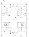
- Fig. 1 shows the finished connection and support bracket 10, ready for use, according to the present invention.
- connection and support bracket 10 is provided with a first and second support and holding seating 16, 17, located on the same support plane 21.
- the first and second support and holding seatings 16, 17 are both open on the same side of the support plane 21.
- first support and holding seating 16 and the second support and holding seating 17 define the support plane 21 on which the section bars 11 are positioned, for example with their base wings 13, during use.
- the support plane 21 therefore defines the bottom wall of the first support and holding seating 16 and the second support and holding seating 17.
- the support and holding seatings 16 and 17 intersect each other in correspondence with a common central area in which the connection node 20 is positioned between the section bars 11 during use.
- the common central area can have a rectangular shape, in the case shown, square.
- the first support and holding seating 16 and the second support and holding seating 17 intersect with each other, in this case in the form of a cross.
- This positioning of the support and holding seatings 16 and 17 allows to define a corresponding cross shape of the support plane 21.
- the first support and holding seating 16 extends along the first axis 18 and the second support and holding seating 17 extends along the second axis 19 which intersects the first axis 18.
- the angle ⁇ between the first axis 18 and the second axis 19 can be 90°.
- the first support and holding seating 16 and the second support and holding seating 17 are configured to support and correctly position the section bars 11 with respect to the bracket 10.
- the bracket 10 is also provided with multiple-function bodies 22 configured to prevent lateral and vertical displacements of the section bars 11 and provided with elastic tongues 23.
- the multiple-function bodies 22 at least partly define the two support and holding seatings 16 and 17, or at least the lateral walls thereof.
- the multiple-function bodies 22 can be associated with the support plane 21.
- the bracket 10 comprises four multiple-function bodies 22 each of which is disposed in correspondence with one of the concave zones, that is, the corners, defined by the cross shape of the support plane 21.
- the multiple-function bodies 22 have a height that varies from 40% to 80% of the width of the support and holding seatings 16, 17 and hence of the base of the section bar 11, advantageously between 50% and 70%.
- the bracket 10 prevents the vertical movements of the section bars 11 by means of the elastic tongues 23, which are positioned in snap-in mode and removably on the base wings 13 of the section bar 11, clamping them vertically, holding the section bar 11 correctly and stably in the respective support and holding seatings 16, 17.
- the elastic tongues 23 do not reach the support plane 21 and are enabled to cooperate stably on the upper part of a base wing 13 of the section bar 11.
- the multiple-function bodies 22 comprise lateral walls 25 that extend substantially vertically with respect to the support plane 21.
- each lateral wall 25 is connected and extends transversely to the support plane 21, in this case orthogonally.
- the lateral walls 25 of the plurality of multiple-function bodies 22 define the sides, that is, walls of the first support and holding seating 16.
- the lateral walls 25 also have the function of containing the lateral movements of the section bar or bars 11 which are inserted into the first housing seating 16.
- the lateral walls 25 of at least one pair of multiple-function bodies 22 are facing each other with respect to the first support and holding seating 16.
- the lateral wall 25 is obtained by bending a portion of sheet along a bending line that extends substantially parallel to the first axis 18.
- the lateral walls 25, or at least some of them, are provided with elastic tongues 23 configured to prevent the section bar 11 from moving vertically in the respective support and holding seating 16, 17.
- the elastic tongues 23 perform a holding action on the section bars 11 in the support and holding seatings 16, for example maintaining the base wings 13 resting against the support plane 21.
- the elastic tongues 23 are made by shearing a portion of the respective lateral wall 25, and are provided with a contact end that faces toward the support plane 21.
- the contact ends of the elastic tongues 23 are distanced from the support plane 21 by a distance substantially equal to or greater than the thickness of the base wings 13 of the section bars 11. This allows to position and hold the base wings 13 of the section bars 11 in the interspace comprised between the contact end and the support plane 21.
- the elastic tongues 23 are bent toward the inside of the respective support and holding seating 16 by an angle of inclination ⁇ ( fig. 3 ) comprised between 1° and 10°, with respect to the respective lateral wall 25 in which it is made.
- the elastic tongues 23 elastically deform to allow the subsequent clamping and holding of the section bars themselves.
- Each multiple-function body 22 also comprises an elastic positioning wall 30 and a lateral extension 26 to which the lateral wall 25 and the elastic positioning wall 30 are connected.
- the lateral extensions 26 of the multiple-function bodies 22 all lie on a common lying plane.
- the lateral extensions 26 can be connected to the lateral walls 25 in correspondence with a bending line which, in this specific case, is substantially parallel to the first axis 18.
- the lateral extensions 26 extend toward the outside with respect to the support and holding seatings 16 and 17.
- the lateral extensions 26 are configured to allow the operator a better grip on the bracket 10, simplifying the step of installing the bracket 10.
- the lateral extensions 26 are provided with at least one fastening mean 27 to fasten an attachment element 28 for a covering and enhancing panel 29.
- the fastening mean 27 is located outside the support and holding seatings 16 and 17.
- the fastening mean comprises a hole 27 made through in the lateral extension 26.
- the hole 27 has an axis orthogonal to a plane parallel to the support plane 21.
- the fastening mean can comprise one or more hooks.
- the attachment element 28 is defined by a pair of segments reciprocally and elastically connected to each other to define a V shape.
- the attachment element 28 can comprise a fastening portion, provided in correspondence with the apex of the V-shape, which allows connection to the covering and enhancing panel 29.
- the segments of the attachment element 28 are divergent and, by means of their elastic deformation, can be inserted into the hole 27.
- the elastic positioning walls 30 are also made in continuity with the lateral extensions 26 and, during use, are located substantially vertical with respect to the support plane 21.
- the elastic positioning walls 30 extend transversely to the flat development of the lateral extensions 26 and the support plane 21, and each of them extends from the respective lateral extension 26 toward the support plane 21.
- the elastic positioning walls 30 are connected to the lateral extensions 26 in correspondence with respective bending lines located substantially parallel to the second axis 19.
- the elastic positioning walls 30 can be elastically deformable around the bending lines to allow, for example, the operations of connecting the bracket 10 to the section bars 11.
- the bending line provided between the lateral wall 25 and the lateral extension 26 is orthogonal to the bending line provided between the lateral extension 26 and the elastic positioning wall 30.
- the elastic positioning walls 30 are not directly connected to the support plane 21 but are connected through the respective lateral walls 25 and the lateral extensions 26.
- the elastic positioning walls 30 of the plurality of bodies 22 define part, that is, the sides, of the second support and holding seating 17.
- the elastic positioning walls 30 are facing each other with respect to the same second support and holding seating 17.
- the elastic positioning walls 30 are located transverse to both the support plane 21 and the lateral walls 25.
- the elastic positioning walls 30 are provided with a contact end facing during use toward the support plane 21 which, during use, cooperates with the at least one section bar 11.
- the contact ends of the elastic positioning walls 30 are distanced from the support plane 21 by a distance substantially equal to or greater than the thickness of the base wings 13 of the section bars 11.
- the elastic positioning walls 30 are inclined toward an internal zone of the second support and holding seating 17 so that their contact ends are overlapping over the support plane 21.
- the elastic positioning walls 30 are inclined toward an internal zone of the second support and holding seating 17 by an angle of inclination ⁇ ( fig. 4 ) with respect to an axis orthogonal to the support plane 21, which is comprised between 1° and 10°.
- the present invention also concerns a method to install a bracket 10 that provides to associate the section bars 11 with the respective base wings 13 to the support and holding seatings 16, 17.
- the support and holding seatings 16, 17 are orthogonal to each other and lie on the same supporting plane 21 of a connection and support bracket 10.
- the base wings 13 are laterally constrained by multiple-function bodies 22 which are also able to act vertically on the base wings 13 of the section bar 11 by means of elastic tongues 23, clamping the vertical movement of the base wings 13.
- the installation method, according to the present invention is also extremely rapid, safe and simple.
- connection and support bracket 10 and corresponding installation method as described heretofore, without departing from the field and scope of the present invention.
- connection and support bracket 10 and corresponding installation method having the characteristics as set forth in the claims and hence all coming within the field of protection defined thereby.
Landscapes
- Engineering & Computer Science (AREA)
- Architecture (AREA)
- Physics & Mathematics (AREA)
- Electromagnetism (AREA)
- Civil Engineering (AREA)
- Structural Engineering (AREA)
- Connection Of Plates (AREA)
- Rear-View Mirror Devices That Are Mounted On The Exterior Of The Vehicle (AREA)
- Forklifts And Lifting Vehicles (AREA)
Applications Claiming Priority (1)
| Application Number | Priority Date | Filing Date | Title |
|---|---|---|---|
| IT102016000099509A IT201600099509A1 (it) | 2016-10-04 | 2016-10-04 | Staffa di collegamento e supporto |
Publications (2)
| Publication Number | Publication Date |
|---|---|
| EP3306006A1 true EP3306006A1 (de) | 2018-04-11 |
| EP3306006B1 EP3306006B1 (de) | 2021-12-01 |
Family
ID=57910033
Family Applications (1)
| Application Number | Title | Priority Date | Filing Date |
|---|---|---|---|
| EP17194647.8A Not-in-force EP3306006B1 (de) | 2016-10-04 | 2017-10-03 | Verbindungs- und stützbügel |
Country Status (2)
| Country | Link |
|---|---|
| EP (1) | EP3306006B1 (de) |
| IT (1) | IT201600099509A1 (de) |
Cited By (2)
| Publication number | Priority date | Publication date | Assignee | Title |
|---|---|---|---|---|
| CN112221439A (zh) * | 2020-09-09 | 2021-01-15 | 中石化宁波工程有限公司 | 用于微通道反应器的分布板及具有其的微通道反应器 |
| EP4474589A1 (de) * | 2024-02-26 | 2024-12-11 | FELKO Bau-Systeme GmbH | Deckentraverseneckbügel und deckentraverse |
Citations (8)
| Publication number | Priority date | Publication date | Assignee | Title |
|---|---|---|---|---|
| US3119475A (en) | 1961-12-14 | 1964-01-28 | Rollform Inc | Ceiling grid system |
| US3334309A (en) | 1966-02-01 | 1967-08-01 | Fairchild Camera Instr Co | Light-to-frequency converter circuit |
| US3343309A (en) | 1965-06-08 | 1967-09-26 | Integrated Systems Inc | Coved ceiling assembly and bracket means therefor |
| US3785110A (en) | 1971-01-14 | 1974-01-15 | Illinois Tool Works | Modular ceiling connector |
| US4438613A (en) * | 1981-06-25 | 1984-03-27 | Decoustics Limited | Suspended ceiling panel system |
| US5428930A (en) * | 1993-07-23 | 1995-07-04 | Decoustics Limited | Concealed grid ceiling panel system |
| US20060218871A1 (en) | 2005-04-04 | 2006-10-05 | Wendt Alan C | Clip for attaching ceiling panels to T-grid |
| WO2008090579A2 (en) | 2007-01-24 | 2008-07-31 | Antonio Guerrasio S.R.L. | Suspended ceiling system using existing reversed t-bar ceiling supports |
-
2016
- 2016-10-04 IT IT102016000099509A patent/IT201600099509A1/it unknown
-
2017
- 2017-10-03 EP EP17194647.8A patent/EP3306006B1/de not_active Not-in-force
Patent Citations (8)
| Publication number | Priority date | Publication date | Assignee | Title |
|---|---|---|---|---|
| US3119475A (en) | 1961-12-14 | 1964-01-28 | Rollform Inc | Ceiling grid system |
| US3343309A (en) | 1965-06-08 | 1967-09-26 | Integrated Systems Inc | Coved ceiling assembly and bracket means therefor |
| US3334309A (en) | 1966-02-01 | 1967-08-01 | Fairchild Camera Instr Co | Light-to-frequency converter circuit |
| US3785110A (en) | 1971-01-14 | 1974-01-15 | Illinois Tool Works | Modular ceiling connector |
| US4438613A (en) * | 1981-06-25 | 1984-03-27 | Decoustics Limited | Suspended ceiling panel system |
| US5428930A (en) * | 1993-07-23 | 1995-07-04 | Decoustics Limited | Concealed grid ceiling panel system |
| US20060218871A1 (en) | 2005-04-04 | 2006-10-05 | Wendt Alan C | Clip for attaching ceiling panels to T-grid |
| WO2008090579A2 (en) | 2007-01-24 | 2008-07-31 | Antonio Guerrasio S.R.L. | Suspended ceiling system using existing reversed t-bar ceiling supports |
Cited By (2)
| Publication number | Priority date | Publication date | Assignee | Title |
|---|---|---|---|---|
| CN112221439A (zh) * | 2020-09-09 | 2021-01-15 | 中石化宁波工程有限公司 | 用于微通道反应器的分布板及具有其的微通道反应器 |
| EP4474589A1 (de) * | 2024-02-26 | 2024-12-11 | FELKO Bau-Systeme GmbH | Deckentraverseneckbügel und deckentraverse |
Also Published As
| Publication number | Publication date |
|---|---|
| EP3306006B1 (de) | 2021-12-01 |
| IT201600099509A1 (it) | 2018-04-04 |
Similar Documents
| Publication | Publication Date | Title |
|---|---|---|
| AU2016234925B2 (en) | Slide clip | |
| US4073114A (en) | Insert assembly for use in pre-stressed concrete structures | |
| RU2496952C2 (ru) | Сейсмическое крепление для т-образной детали деформационного шва решетчатой конструкции | |
| EP3068957B1 (de) | Kleiderbügelschiene für eine tragrahmenstruktur einer zwischendecke | |
| TW201122196A (en) | Seismic clip | |
| US20170342736A1 (en) | Track system for supporting wall studs | |
| KR102641569B1 (ko) | 지지 헤드, 천장 지지부, 및 이러한 천장 지지부를 구비한 천장 거푸집 | |
| MX2015002839A (es) | Sistema de techo de rejilla oculta. | |
| EP3306006B1 (de) | Verbindungs- und stützbügel | |
| GB2125137A (en) | Attachment device | |
| RU2672701C2 (ru) | Потолочная подвесная система | |
| US9745747B2 (en) | Suspended ceiling grid adapter | |
| JP2009102909A (ja) | 埋込金物およびその取り付け方法 | |
| JP6778090B2 (ja) | ハンガーと該ハンガーを用いたシステム天井構造 | |
| JP2020026726A (ja) | 幅木及び幅木の設置構造 | |
| KR102070755B1 (ko) | 천장 프레임 체결용 고강도 행거 | |
| EP3571357B1 (de) | Driftklammer | |
| US1838120A (en) | Building structure | |
| KR102848214B1 (ko) | 상하걸림 보강유닛 | |
| US12110684B2 (en) | Clip, ceiling base, and method for constructing same | |
| EP4153822B1 (de) | Trockenbau-verbinder, trockenbau-anordnung, bausatz und verfahren zur herstellung einer trockenbau-decke | |
| CA3158758C (en) | Ceiling clip with engaging projections, ceiling base, and method for constructing same | |
| CA3113936A1 (en) | Multi-directional beam for a drywall ceiling soffit related application | |
| KR20090011851U (ko) | 광폭 클립 체결공을 갖는 천장 보드용 메인 티바 | |
| JP2513643Y2 (ja) | 格子状天井材の固定金具 |
Legal Events
| Date | Code | Title | Description |
|---|---|---|---|
| PUAI | Public reference made under article 153(3) epc to a published international application that has entered the european phase |
Free format text: ORIGINAL CODE: 0009012 |
|
| STAA | Information on the status of an ep patent application or granted ep patent |
Free format text: STATUS: THE APPLICATION HAS BEEN PUBLISHED |
|
| AK | Designated contracting states |
Kind code of ref document: A1 Designated state(s): AL AT BE BG CH CY CZ DE DK EE ES FI FR GB GR HR HU IE IS IT LI LT LU LV MC MK MT NL NO PL PT RO RS SE SI SK SM TR |
|
| AX | Request for extension of the european patent |
Extension state: BA ME |
|
| STAA | Information on the status of an ep patent application or granted ep patent |
Free format text: STATUS: REQUEST FOR EXAMINATION WAS MADE |
|
| 17P | Request for examination filed |
Effective date: 20181011 |
|
| RBV | Designated contracting states (corrected) |
Designated state(s): AL AT BE BG CH CY CZ DE DK EE ES FI FR GB GR HR HU IE IS IT LI LT LU LV MC MK MT NL NO PL PT RO RS SE SI SK SM TR |
|
| GRAP | Despatch of communication of intention to grant a patent |
Free format text: ORIGINAL CODE: EPIDOSNIGR1 |
|
| STAA | Information on the status of an ep patent application or granted ep patent |
Free format text: STATUS: GRANT OF PATENT IS INTENDED |
|
| INTG | Intention to grant announced |
Effective date: 20210504 |
|
| GRAS | Grant fee paid |
Free format text: ORIGINAL CODE: EPIDOSNIGR3 |
|
| GRAA | (expected) grant |
Free format text: ORIGINAL CODE: 0009210 |
|
| STAA | Information on the status of an ep patent application or granted ep patent |
Free format text: STATUS: THE PATENT HAS BEEN GRANTED |
|
| AK | Designated contracting states |
Kind code of ref document: B1 Designated state(s): AL AT BE BG CH CY CZ DE DK EE ES FI FR GB GR HR HU IE IS IT LI LT LU LV MC MK MT NL NO PL PT RO RS SE SI SK SM TR |
|
| REG | Reference to a national code |
Ref country code: GB Ref legal event code: FG4D |
|
| REG | Reference to a national code |
Ref country code: AT Ref legal event code: REF Ref document number: 1451893 Country of ref document: AT Kind code of ref document: T Effective date: 20211215 Ref country code: CH Ref legal event code: EP |
|
| REG | Reference to a national code |
Ref country code: IE Ref legal event code: FG4D |
|
| REG | Reference to a national code |
Ref country code: DE Ref legal event code: R096 Ref document number: 602017050076 Country of ref document: DE |
|
| REG | Reference to a national code |
Ref country code: LT Ref legal event code: MG9D |
|
| REG | Reference to a national code |
Ref country code: NL Ref legal event code: MP Effective date: 20211201 |
|
| REG | Reference to a national code |
Ref country code: AT Ref legal event code: MK05 Ref document number: 1451893 Country of ref document: AT Kind code of ref document: T Effective date: 20211201 |
|
| PG25 | Lapsed in a contracting state [announced via postgrant information from national office to epo] |
Ref country code: RS Free format text: LAPSE BECAUSE OF FAILURE TO SUBMIT A TRANSLATION OF THE DESCRIPTION OR TO PAY THE FEE WITHIN THE PRESCRIBED TIME-LIMIT Effective date: 20211201 Ref country code: LT Free format text: LAPSE BECAUSE OF FAILURE TO SUBMIT A TRANSLATION OF THE DESCRIPTION OR TO PAY THE FEE WITHIN THE PRESCRIBED TIME-LIMIT Effective date: 20211201 Ref country code: FI Free format text: LAPSE BECAUSE OF FAILURE TO SUBMIT A TRANSLATION OF THE DESCRIPTION OR TO PAY THE FEE WITHIN THE PRESCRIBED TIME-LIMIT Effective date: 20211201 Ref country code: BG Free format text: LAPSE BECAUSE OF FAILURE TO SUBMIT A TRANSLATION OF THE DESCRIPTION OR TO PAY THE FEE WITHIN THE PRESCRIBED TIME-LIMIT Effective date: 20220301 Ref country code: AT Free format text: LAPSE BECAUSE OF FAILURE TO SUBMIT A TRANSLATION OF THE DESCRIPTION OR TO PAY THE FEE WITHIN THE PRESCRIBED TIME-LIMIT Effective date: 20211201 |
|
| PG25 | Lapsed in a contracting state [announced via postgrant information from national office to epo] |
Ref country code: SE Free format text: LAPSE BECAUSE OF FAILURE TO SUBMIT A TRANSLATION OF THE DESCRIPTION OR TO PAY THE FEE WITHIN THE PRESCRIBED TIME-LIMIT Effective date: 20211201 Ref country code: PL Free format text: LAPSE BECAUSE OF FAILURE TO SUBMIT A TRANSLATION OF THE DESCRIPTION OR TO PAY THE FEE WITHIN THE PRESCRIBED TIME-LIMIT Effective date: 20211201 Ref country code: NO Free format text: LAPSE BECAUSE OF FAILURE TO SUBMIT A TRANSLATION OF THE DESCRIPTION OR TO PAY THE FEE WITHIN THE PRESCRIBED TIME-LIMIT Effective date: 20220301 Ref country code: LV Free format text: LAPSE BECAUSE OF FAILURE TO SUBMIT A TRANSLATION OF THE DESCRIPTION OR TO PAY THE FEE WITHIN THE PRESCRIBED TIME-LIMIT Effective date: 20211201 Ref country code: HR Free format text: LAPSE BECAUSE OF FAILURE TO SUBMIT A TRANSLATION OF THE DESCRIPTION OR TO PAY THE FEE WITHIN THE PRESCRIBED TIME-LIMIT Effective date: 20211201 Ref country code: GR Free format text: LAPSE BECAUSE OF FAILURE TO SUBMIT A TRANSLATION OF THE DESCRIPTION OR TO PAY THE FEE WITHIN THE PRESCRIBED TIME-LIMIT Effective date: 20220302 Ref country code: ES Free format text: LAPSE BECAUSE OF FAILURE TO SUBMIT A TRANSLATION OF THE DESCRIPTION OR TO PAY THE FEE WITHIN THE PRESCRIBED TIME-LIMIT Effective date: 20211201 |
|
| PG25 | Lapsed in a contracting state [announced via postgrant information from national office to epo] |
Ref country code: NL Free format text: LAPSE BECAUSE OF FAILURE TO SUBMIT A TRANSLATION OF THE DESCRIPTION OR TO PAY THE FEE WITHIN THE PRESCRIBED TIME-LIMIT Effective date: 20211201 |
|
| PG25 | Lapsed in a contracting state [announced via postgrant information from national office to epo] |
Ref country code: SM Free format text: LAPSE BECAUSE OF FAILURE TO SUBMIT A TRANSLATION OF THE DESCRIPTION OR TO PAY THE FEE WITHIN THE PRESCRIBED TIME-LIMIT Effective date: 20211201 Ref country code: SK Free format text: LAPSE BECAUSE OF FAILURE TO SUBMIT A TRANSLATION OF THE DESCRIPTION OR TO PAY THE FEE WITHIN THE PRESCRIBED TIME-LIMIT Effective date: 20211201 Ref country code: RO Free format text: LAPSE BECAUSE OF FAILURE TO SUBMIT A TRANSLATION OF THE DESCRIPTION OR TO PAY THE FEE WITHIN THE PRESCRIBED TIME-LIMIT Effective date: 20211201 Ref country code: PT Free format text: LAPSE BECAUSE OF FAILURE TO SUBMIT A TRANSLATION OF THE DESCRIPTION OR TO PAY THE FEE WITHIN THE PRESCRIBED TIME-LIMIT Effective date: 20220401 Ref country code: EE Free format text: LAPSE BECAUSE OF FAILURE TO SUBMIT A TRANSLATION OF THE DESCRIPTION OR TO PAY THE FEE WITHIN THE PRESCRIBED TIME-LIMIT Effective date: 20211201 Ref country code: CZ Free format text: LAPSE BECAUSE OF FAILURE TO SUBMIT A TRANSLATION OF THE DESCRIPTION OR TO PAY THE FEE WITHIN THE PRESCRIBED TIME-LIMIT Effective date: 20211201 |
|
| REG | Reference to a national code |
Ref country code: DE Ref legal event code: R097 Ref document number: 602017050076 Country of ref document: DE |
|
| PG25 | Lapsed in a contracting state [announced via postgrant information from national office to epo] |
Ref country code: IS Free format text: LAPSE BECAUSE OF FAILURE TO SUBMIT A TRANSLATION OF THE DESCRIPTION OR TO PAY THE FEE WITHIN THE PRESCRIBED TIME-LIMIT Effective date: 20220401 |
|
| PLBE | No opposition filed within time limit |
Free format text: ORIGINAL CODE: 0009261 |
|
| STAA | Information on the status of an ep patent application or granted ep patent |
Free format text: STATUS: NO OPPOSITION FILED WITHIN TIME LIMIT |
|
| PG25 | Lapsed in a contracting state [announced via postgrant information from national office to epo] |
Ref country code: DK Free format text: LAPSE BECAUSE OF FAILURE TO SUBMIT A TRANSLATION OF THE DESCRIPTION OR TO PAY THE FEE WITHIN THE PRESCRIBED TIME-LIMIT Effective date: 20211201 Ref country code: AL Free format text: LAPSE BECAUSE OF FAILURE TO SUBMIT A TRANSLATION OF THE DESCRIPTION OR TO PAY THE FEE WITHIN THE PRESCRIBED TIME-LIMIT Effective date: 20211201 |
|
| 26N | No opposition filed |
Effective date: 20220902 |
|
| PG25 | Lapsed in a contracting state [announced via postgrant information from national office to epo] |
Ref country code: SI Free format text: LAPSE BECAUSE OF FAILURE TO SUBMIT A TRANSLATION OF THE DESCRIPTION OR TO PAY THE FEE WITHIN THE PRESCRIBED TIME-LIMIT Effective date: 20211201 |
|
| REG | Reference to a national code |
Ref country code: DE Ref legal event code: R119 Ref document number: 602017050076 Country of ref document: DE |
|
| PG25 | Lapsed in a contracting state [announced via postgrant information from national office to epo] |
Ref country code: MC Free format text: LAPSE BECAUSE OF FAILURE TO SUBMIT A TRANSLATION OF THE DESCRIPTION OR TO PAY THE FEE WITHIN THE PRESCRIBED TIME-LIMIT Effective date: 20211201 Ref country code: IT Free format text: LAPSE BECAUSE OF FAILURE TO SUBMIT A TRANSLATION OF THE DESCRIPTION OR TO PAY THE FEE WITHIN THE PRESCRIBED TIME-LIMIT Effective date: 20211201 |
|
| REG | Reference to a national code |
Ref country code: CH Ref legal event code: PL |
|
| REG | Reference to a national code |
Ref country code: BE Ref legal event code: MM Effective date: 20221031 |
|
| GBPC | Gb: european patent ceased through non-payment of renewal fee |
Effective date: 20221003 |
|
| PG25 | Lapsed in a contracting state [announced via postgrant information from national office to epo] |
Ref country code: LU Free format text: LAPSE BECAUSE OF NON-PAYMENT OF DUE FEES Effective date: 20221003 |
|
| PG25 | Lapsed in a contracting state [announced via postgrant information from national office to epo] |
Ref country code: LI Free format text: LAPSE BECAUSE OF NON-PAYMENT OF DUE FEES Effective date: 20221031 Ref country code: FR Free format text: LAPSE BECAUSE OF NON-PAYMENT OF DUE FEES Effective date: 20221031 Ref country code: DE Free format text: LAPSE BECAUSE OF NON-PAYMENT OF DUE FEES Effective date: 20230503 Ref country code: CH Free format text: LAPSE BECAUSE OF NON-PAYMENT OF DUE FEES Effective date: 20221031 |
|
| PG25 | Lapsed in a contracting state [announced via postgrant information from national office to epo] |
Ref country code: BE Free format text: LAPSE BECAUSE OF NON-PAYMENT OF DUE FEES Effective date: 20221031 |
|
| PG25 | Lapsed in a contracting state [announced via postgrant information from national office to epo] |
Ref country code: IE Free format text: LAPSE BECAUSE OF NON-PAYMENT OF DUE FEES Effective date: 20221003 Ref country code: GB Free format text: LAPSE BECAUSE OF NON-PAYMENT OF DUE FEES Effective date: 20221003 |
|
| PG25 | Lapsed in a contracting state [announced via postgrant information from national office to epo] |
Ref country code: HU Free format text: LAPSE BECAUSE OF FAILURE TO SUBMIT A TRANSLATION OF THE DESCRIPTION OR TO PAY THE FEE WITHIN THE PRESCRIBED TIME-LIMIT; INVALID AB INITIO Effective date: 20171003 |
|
| PG25 | Lapsed in a contracting state [announced via postgrant information from national office to epo] |
Ref country code: CY Free format text: LAPSE BECAUSE OF FAILURE TO SUBMIT A TRANSLATION OF THE DESCRIPTION OR TO PAY THE FEE WITHIN THE PRESCRIBED TIME-LIMIT Effective date: 20211201 |
|
| PG25 | Lapsed in a contracting state [announced via postgrant information from national office to epo] |
Ref country code: MK Free format text: LAPSE BECAUSE OF FAILURE TO SUBMIT A TRANSLATION OF THE DESCRIPTION OR TO PAY THE FEE WITHIN THE PRESCRIBED TIME-LIMIT Effective date: 20211201 |
|
| PG25 | Lapsed in a contracting state [announced via postgrant information from national office to epo] |
Ref country code: MT Free format text: LAPSE BECAUSE OF FAILURE TO SUBMIT A TRANSLATION OF THE DESCRIPTION OR TO PAY THE FEE WITHIN THE PRESCRIBED TIME-LIMIT Effective date: 20211201 |
|
| PG25 | Lapsed in a contracting state [announced via postgrant information from national office to epo] |
Ref country code: TR Free format text: LAPSE BECAUSE OF FAILURE TO SUBMIT A TRANSLATION OF THE DESCRIPTION OR TO PAY THE FEE WITHIN THE PRESCRIBED TIME-LIMIT Effective date: 20211201 |