EP3306016A1 - Türdrücker - Google Patents
Türdrücker Download PDFInfo
- Publication number
- EP3306016A1 EP3306016A1 EP17194795.5A EP17194795A EP3306016A1 EP 3306016 A1 EP3306016 A1 EP 3306016A1 EP 17194795 A EP17194795 A EP 17194795A EP 3306016 A1 EP3306016 A1 EP 3306016A1
- Authority
- EP
- European Patent Office
- Prior art keywords
- actuating
- door handle
- guide
- door
- axis
- Prior art date
- Legal status (The legal status is an assumption and is not a legal conclusion. Google has not performed a legal analysis and makes no representation as to the accuracy of the status listed.)
- Granted
Links
Images




Classifications
-
- E—FIXED CONSTRUCTIONS
- E05—LOCKS; KEYS; WINDOW OR DOOR FITTINGS; SAFES
- E05B—LOCKS; ACCESSORIES THEREFOR; HANDCUFFS
- E05B5/00—Handles completely let into the surface of the wing
- E05B5/006—Handles completely let into the surface of the wing essentially defining a completely closed surface together with the wing
-
- E—FIXED CONSTRUCTIONS
- E05—LOCKS; KEYS; WINDOW OR DOOR FITTINGS; SAFES
- E05B—LOCKS; ACCESSORIES THEREFOR; HANDCUFFS
- E05B5/00—Handles completely let into the surface of the wing
-
- E—FIXED CONSTRUCTIONS
- E05—LOCKS; KEYS; WINDOW OR DOOR FITTINGS; SAFES
- E05C—BOLTS OR FASTENING DEVICES FOR WINGS, SPECIALLY FOR DOORS OR WINDOWS
- E05C1/00—Fastening devices with bolts moving rectilinearly
- E05C1/08—Fastening devices with bolts moving rectilinearly with latching action
- E05C1/12—Fastening devices with bolts moving rectilinearly with latching action with operating handle or equivalent member moving otherwise than rigidly with the latch
- E05C1/14—Fastening devices with bolts moving rectilinearly with latching action with operating handle or equivalent member moving otherwise than rigidly with the latch the handle or member moving essentially towards or away from the plane of the wing or frame
- E05C1/145—Fastening devices with bolts moving rectilinearly with latching action with operating handle or equivalent member moving otherwise than rigidly with the latch the handle or member moving essentially towards or away from the plane of the wing or frame flush
-
- E—FIXED CONSTRUCTIONS
- E05—LOCKS; KEYS; WINDOW OR DOOR FITTINGS; SAFES
- E05B—LOCKS; ACCESSORIES THEREFOR; HANDCUFFS
- E05B53/00—Operation or control of locks by mechanical transmissions, e.g. from a distance
- E05B53/003—Operation or control of locks by mechanical transmissions, e.g. from a distance flexible
-
- E—FIXED CONSTRUCTIONS
- E05—LOCKS; KEYS; WINDOW OR DOOR FITTINGS; SAFES
- E05C—BOLTS OR FASTENING DEVICES FOR WINGS, SPECIALLY FOR DOORS OR WINDOWS
- E05C9/00—Arrangements of simultaneously actuated bolts or other securing devices at well-separated positions on the same wing
Definitions
- the invention relates to the field of fittings for windows or doors, and more particularly to a door handle for opening a door, for example for actuating a lock.
- Conventional door handle which act to open a door for the operation of a door lock on the lock shaft, are designed as pawls.
- Such door handle or doorknobs are disturbing or dangerous, such. Inside sports halls, where they could cause injuries as protruding parts, in hospitals where they can get caught in beds, in elevators, campers or horse boxes, etc. This also applies to escape doors and / or fire doors used in corridors and corridors, for example are arranged and which are usually open and close only in an emergency. And a use of the usual door handles in sliding doors is connected because of your supernatant with disadvantages and requires complicated door designs.
- Door handles are combined, for example, with standard locks, typically mortise locks, wherein the movement transmission or power transmission via a square, which is inserted into a pusher, a central, round insert in the lock (hereinafter, the term "lock nut” is used).
- the inserted lock sits in a lock pocket worked out in the door leaf and is screwed to the door leaf on a so-called cuff.
- a nut spring also provides Called contra spring, hereinafter referred to as a lock spring, that lock nut, square and door handle move back to the starting position.
- Door handles can also be combined with door retainers different from door locks.
- a door holding member is an element capable of holding a door leaf in a locked closed state and capable of bringing the door leaf into an unlocked and openable state by operation of the door holding member.
- a door holding element is an openable lock of a door leaf.
- door holding elements such as door traps may be formed and arranged at an upper and / or lower end of the door leaf.
- Door handles can be used to operate door retaining elements in door leaves that do not include a door lock, for example in embodiments of escape doors or fire doors without a door lock.
- door handles are used in various forms, for example as a door handle, shell handle or panic bars (also known as "touchbar").
- the door handle and the panic bar stand out clearly from the door leaf, sometimes also a shell handle. This is a potential source of injury. Parts of standard door handles can also damage objects or walls when in contact. Depending on the design and opening direction of the door, structural adjustments or complicated constructions are necessary. Restrictions such as a limited maximum opening width of the door leaf and / or a minimum distance of the door leaf from a wall in the open state of the door can also be expected.
- Shell handles are indeed flat and some do not have the above disadvantages. But designed as a shell handle door handle are complicated.
- the operation of the usual door handle can cause various problems. In most cases, rotation, pulling or pushing in a movement other than the direction of movement of the door leaf is still needed to operate the door handle and another movement to move the door leaf. A sequence of movements in two different directions (such as turning and pressing, or pressing down and then back) is not always intuitively clear. If two different movements have to be carried out in succession, a door can only be opened and / or closed at low speed. Path length, direction, applied force and sequence of movements required to operate one of the usual door handles can vary widely and are not always quick and easy to recognize.
- the usual door handles are designed for the average person's ability. In particular, children, the disabled, elderly and / or frail people and / or people in stressful situations can make trouble with the use of conventional door handles.
- a door handle for actuating a door handle separately formed and rotatable about a transmission axis shaft or nut to Opening a door
- a transmission element of the door handle is arranged rotatably about the transmission axis and the door handle has an actuating element, an actuating guide and a transmission unit.
- the actuating element in this case comprises an actuating surface, wherein the actuating element is movable by a force acting on the actuating surface from a closed position to an open position.
- the actuating surface is arranged both in the closed position and in the open position in each case substantially normal to the transmission axis.
- the actuating guide has an actuating guide track along which the actuating element is movable from the closed position to the open position.
- the actuating guide track is formed parallel to the transmission axis.
- the transmission unit is capable of converting a movement of the actuating element from the closed position to the open position into a rotation of the transmission element.
- a surface is arranged substantially normal to an axis when a smoothed outer contour of a projection of that surface on a plane comprising the axis does not deviate more than 15 angular degrees from a perpendicular to the axis.
- the deviation is a maximum of 10 angular degrees.
- the deviation can be a maximum of 5 degrees.
- smoothed outer contour is meant that any interruptions or small deformations such as ribs, knobs furrows, grooves or waves are replaced by corresponding short straight connectors.
- the actuating surface is arranged both in the closed position and in the open position in each case normal to the transmission axis.
- a device for opening a door for example, among other things, for actuating a Door holding element and / or a lock, in particular a door lock or window lock.
- the operation can be done by moving an actuator against the door handle and, for example, a door out, but also by pulling an actuator away from the door handle and, for example, from a door.
- the term “pusher” is used in both cases.
- the term “pusher” includes, for example, impact plates, printing plates.
- the door handle can be realized as a "push” variant, which respectively when pressing the actuator plate against the door handle resp. the door opens the lock and / or the door holding element, or as a "pull” variant, which respectively when pulling the actuator plate from the door handle resp. away from the door, the lock and / or the door holding member opens. It makes sense to use these variants so that the direction of movement of the actuator plate corresponds to the opening direction of the door.
- a preferred combination of two such door handles on the same lock thus includes a "push” and a "pull” - door handle.
- the inventive door handle can be used in pairs, or in combination with a doorknob, another type of pusher or no pusher or a doorknob.
- One or two of the door handles can be used with a lock with split locknut (panic lock).
- an actuating surface arranged essentially normal to the transmission axis can be moved in parallel along the transmission axis from the closed position to the open position.
- the door handle is operated and, for example, brought the door leaf in a movable state.
- the door leaf By continuing the same movement in the same direction, namely parallel along the transmission axis, can now for example, the door leaf to be moved.
- the door can thus be opened - either by pushing or pulling.
- Damage and / or injury can be prevented or minimized, since even if parts of such a door handle protrude from the door leaf, they are movable in the direction of the transmission axis and can yield.
- the movement of the actuating surface parallel along the transmission axis can be made possible with a compact design. This allows the supernatant over the door panel and associated disadvantages minimized or eliminated. On complicated constructions of door frames or other parts outside the door panel can be dispensed with. With the construction based on movement in one direction only, the door handle can be designed so that a large circle of users can easily operate it.
- the movement of the actuating surface in parallel along the transmission axis can prevent misconduct or reduce its probability.
- a movement parallel along the transmission axis is aligned in the closing or opening direction of the door.
- a faulty manipulation of the door handle would thus cause a closing or opening movement of the door and not only affect the door handle, which makes the faulty manipulation faster recognizable and preventable. Misclassification is more difficult, especially with doors open as far as possible, because the direction of movement of the door handle (along the transmission axis) on the stop side is difficult or impossible to operate.
- Another advantage of the movement of the actuating surface parallel along the transmission axis is the ability to selectively select a size and shape of the actuating surface without limiting the functionality to specific requirements.
- the actuating surface described above can be formed in different sizes and shapes, without the path and / or the force varies depending on the point of application , Depending on the shape, weight, size and / or other factors of the door leaf or the door, the actuating surface can be varied in size and shape, without the operation changes.
- An advantage of the movement of the actuating surface parallel to the transmission axis is that the actuating surface can be actuated at any point in the direction of the transmission axis.
- the door handle can thus be operated on top, bottom, right, left, center and in all combinations thereof on the actuating surface.
- the transmission element has a protruding square, which can be inserted into the lock nut of a lock. This makes it possible to combine the door handle without the use of other parts with a lock.
- the transmission element is a Betsch Trentsnuss, in which a designed as a square lock shaft can be inserted.
- the length of the lock shaft can be selected according to the thickness of the door.
- the actuating guide is designed such that the actuating element is movable only translationally along the actuating guide track.
- a purely translational movement of the actuating element from the open position to the closed position and / or vice versa is advantageous if, for example, an exclusively translatory force is required to move the door leaf. Also, an operation of the door handle is easy and pleasant when only one direction of movement in the operation of the door handle on the hand or another operating element acts.
- the actuating element may for example also be a combination of a translational and rotational movement. Other movements can also be combined with the translational movement.
- the actuator may not be aligned normal to the transmission axis on the way from the open position to closing position and / or back also temporarily. For example, the actuating element can be tilted between these positions.
- the actuating surface comprises a continuous flat surface, which is at least 100 square centimeters in size.
- the flat surface is at least 225 square centimeters in size.
- the flat surface is at least 400 square centimeters in size.
- An actuating surface with a continuous flat surface of a minimum size is easy to operate and low-risk. From a flat surface there is little danger of getting caught or injured.
- a flat surface is easy and inexpensive to produce. Flat surfaces are easy to clean.
- a planar actuating surface can keep a supernatant of the door handle on the door panel despite large operating area low, because about the supernatant is exploited by the entire flat surface maximum.
- the actuating surface may have perforated surfaces.
- the actuating surface can be bent, curved and / or corrugated.
- the actuating surface may also be formed asymmetrically - along and / or transverse to the transmission axis. The shape, size and / or surface finish of the actuating surface can be chosen freely.
- the actuating guide comprises at least two guide elements, which are arranged rotatably about a guide axis of rotation.
- the guide axis of rotation is arranged perpendicular to the transmission axis.
- An arrangement of the guide axis about which guide elements of the actuating guide can rotate, perpendicular to the transmission axis allows a space-saving design in the direction of the transmission axis. So a flat design is possible.
- the guide axis of rotation can also be arranged obliquely to the transmission axis. Or in parallel.
- the guide elements are each arranged rotationally symmetrical about the guide axis of rotation.
- the guide axis of rotation is arranged centrally in the guide elements.
- the guide axis of rotation can also be arranged at other locations than the center of the guide elements.
- the guide axis of rotation is displaceable in the same direction by the movement of the actuating element from the closed position to the open position.
- the guide axis of rotation may also be formed stationary.
- the guide axis of rotation can be moved in a direction other than the actuator, for example, transverse thereto or opposite.
- the guide axis of rotation can also rotate, for example.
- the guide elements substantially each extend from the actuating element to a main body of the door handle.
- the main body of the door handle is an element of the door handle, which is stationary in the installed state of the door handle in the door leaf relative to the door leaf, in particular in an operation of the door handle.
- the actuating element is moved relative to the main body of the door handle.
- the guide elements extend substantially from the actuator to the body when the guide elements projected onto a plane encompassing the transfer axis for at least 80% of the distance between transfer points of the guide elements on the actuator and force transfer points of the guide elements on the body in that projection.
- the guide element extends in the projection over 90% of the distance.
- the guide element can extend over 95% of the distance in the projection.
- force transfer points are meant those points at which attaches a force exerted by the guide elements on the actuator or the base body force. For example, about direct connection points on a rotary joint between the guide element and actuator or body. Or a frictional connection point of a connecting element of the guide element and the actuating element or base body.
- the operating guide elements substantially from the actuator to the body, the operating guide with a few elements can be easily and inexpensively. Manufacturing, maintenance, repair and inspection can be done quickly and cost effectively.
- the guide elements each extend from the actuating element to a base body of the door handle.
- the guide elements may be shorter than the distance between the actuating element and the base body of the door handle.
- the projection elements do not extend beyond the actuating element of the door handle when projected onto a plane encompassing the transmission axis.
- the projection elements do not extend beyond the base body of the door handle when projected onto a plane encompassing the transmission axis.
- one end of a guide element is only rotatable, the other rotatable and at the same time slidably mounted.
- the simultaneous rotation and displaceability can be performed guided by a round connecting element in a backdrop.
- the round connection element can turn around its axis of symmetry and simultaneously move along the scenery.
- This embodiment with a combination of a pure rotary joint and a combined rotary and sliding connection is inexpensive and easy to implement. It is robust and not susceptible to interference.
- the displacement axis may be arranged obliquely to the guide axis of rotation and / or obliquely to the transmission axis.
- a guide element can also have a combined rotary and sliding connection on both sides.
- a guide element for example, on both sides of a pure rotary connection.
- elastic compounds or at least partially elastic guide elements may be used in place of at least one of the aforementioned compounds.
- At least one first guide element has the first connection for the exclusively rotatable movement about an axis parallel to the guide axis of rotation and at least one second guide element the second connection for the exclusively rotatable movement about an axis parallel to the guide axis of rotation.
- At least one guide element is only rotatably connected to the actuating element, and at least one other guide element exclusively rotatable with the main body.
- the exclusively rotatable connection is formed as a continuous connection between the guide element and the actuating element or main body.
- connection By continuous connection is meant a connection which connects two elements together and prevents separation of the two elements from each other.
- the exclusively rotatable connection may comprise a shaft in a holder enclosing the shaft.
- the elements connected by this exclusively rotatable connection can be rotated relative to one another, but can not be separated from one another.
- a first guide member having an exclusively rotatable and continuous connection with the actuating element and a second guide element with a rotatable and simultaneously displaceable and continuous connection with the guide element is that the actuating element is movable relative to the base body only along the transmission axis. Since the two guide elements are rotatable about the same guide axis of rotation and are thus coupled to each other and the exclusively rotatable and continuous connections in turn this couple to actuator and body, actuator and body are interconnected.
- the exclusively rotatable and continuous connections, in combination with the rotatable and at the same time also displaceable connection, ensure that the actuating element can only be moved along the transmission axis relative to the main body.
- the rotatable and at the same time displaceable connection is formed as a continuous connection between the guide element and the actuating element or base body.
- the exclusively rotatable connection and / or the rotatable and at the same time displaceable connection is designed as a separable connection.
- Guide elements can also have on the same side of the exclusively rotatable connection, for example on the body.
- the actuating guide has a fastening device for the actuating element.
- the fastening device has at least one fastening element, which protrudes in an unfastened position of the fastening device into a spatial area around the actuating guide, which is occupied by the actuating element in a fastened position of the fastening device.
- the actuating element is removed from the fastening device and thereby from the actuating guide in the unfastened position.
- the actuating element is fastened to the fastening device and thereby to the actuating guide.
- Such an embodiment may be designed in the form of a snap closure for the actuating element.
- the fastening element protrudes beyond the actuating guide and is pushed away during the fastening of the actuating element on the actuating guide from the actuating element. This movement may trigger a snap mechanism which secures the actuator to the actuator guide.
- a fastener which is displaced by the actuating element in a fastening thereof, allows a simple, rapid and secure attachment of the actuating element to the actuating guide. This makes a simple, quick, safe and intuitive installation of the door handle possible.
- the actuating guide can also be designed without an actuating element and in particular without a fastening device for the actuating element.
- the at least one fastening element protrudes in the mounted position in projection onto the actuating surface beyond an outer contour of a projection of the actuating element on the actuating surface.
- the fastener By protruding or protruding the fastener on the actuator can be easily accessed on the fastener. This allows a simple and rapid operation of the fastening device and in particular a simple and rapid opening of the fastening device.
- the actuator can be easily and quickly solved and removed from the operating guide and thus the door handle. Insbesondre a snap closure for the actuator is easy and quick to solve.
- the fastener may protrude beyond the actuator in the fastened position, but may be disposed within the door handle.
- the at least one fastening element is surrounded in projection in the mounting position on the actuating surface of the outer contour of a projection of the actuating element on the actuating surface.
- the door handle is designed such that it is capable of exerting a torque of at least 5 Nm, in particular of at least 10 Nm and in particular of at least 20 Nm by the movement of the actuating element from the closed position into the open position on the lock shaft or lock nut.
- the door handle therefore has components and elements of a stability which are capable of transmitting a minimum torque via the actuating element to the lock shaft or the lock nut. This allows use of the door handle in combination with door locks in robust and resistant doors, such as room, apartment and front doors. Also emergency doors or access doors to buildings, doors in fences and walls, doors in trains and ships can be equipped with this door handle.
- the door handle can also be designed without a certain minimum torque is transferable.
- the door handle is designed such that acts on the actuating element in the closed position in the direction of the open position into the closed position along the transmission axis, a force of 50N maximum.
- the door handle By counteracting the maximum force of 50N when operating or pressing the door handle (ie the movement of the closed position in the open position), the door handle is easy to operate with little effort.
- the door handle thus fulfills a standard for door handles for emergency doors.
- door handle, the transmission unit and the transmission element via a helical slide guide are positively connected to each other.
- the helical link guide limits a rotation of the transmission element about the transmission axis to a maximum of 60 degrees. In particular, the rotation is limited to a maximum of 45 degrees, and in particular limited to a maximum of 30 degrees.
- a helical slotted guide is an efficient and simple and inexpensive means of translating into a rotation.
- the slide guide can limit the maximum rotation simple, robust and reliable by limiting the path in the slotted guide, for example, by a correspondingly short guide channel and / or by a stop.
- the helical guide can allow the maximum rotation indefinitely.
- On a helical guidance can also be dispensed with.
- a minimum distance of the actuating element from the closed position to the open position is at least 12 mm. In particular, the minimum distance is at least 18mm, and in particular at least 25mm.
- a maximum travel of the actuating element from the closed position to the open position is a maximum of 30 mm.
- the maximum travel is a maximum of 40mm, and in particular a maximum of 50mm.
- Such door handles can be installed to save space and in particular completely sunk in the door leaf.
- a maximum extension of the actuating element in projection onto the actuating surface is at least a factor of 2 greater than a maximum extension of the door handle along the transmission axis.
- the maximum extension of the actuating element in projection onto the actuating surface is greater by a factor of at least 4 than the maximum extent of the door handle along the transmission axis, and in particular by at least a factor of 6.
- maximum expansion is meant a one-dimensional extent, that is, about a length of a diagonal in a square or a diameter of a circle.
- a more wide than high door handle is flat and compact, so that such a door handle can be installed to save space and in particular completely sunk into the door leaf.
- the door handle comprises a fluorescent or phosphorescent element.
- this element is attached to the actuating element and / or is at least a part of the actuating element.
- This element can be attached to the actuating surface or designed as such. The same applies to the end faces of the actuating element.
- / or this element is attached, for example, on the main body of the door handle and / or is at least a part of the body.
- This element may for example be a coating, in particular a paint or a sticker.
- the door handle can also be free of a fluorescent or phosphorescent element.
- the Betschistsnuss is designed to transmit a movement to an inserted square with a game, in particular with a game at an angle of 20 ° to 50 °, in particular 25 ° to 40 °.
- the actuating nut can also be designed without play.
- the invention also includes a door leaf with a door handle as described above.
- the door handle and in particular the actuating surface - with built-in state of the door handle - on a front or a rear side of the door leaf a maximum projection of 3mm.
- the door handle (and in particular the actuating surface) has a maximum projection of 1.5 mm.
- the door handle (and in particular the actuating surface) has a maximum projection of 0 mm - in other words, no projection.
- the door leaf with the door handle can comprise a door lock which can be actuated by the door handle.
- the door leaf with the door handle is optionally formed free of a door lock and in particular comprises at least one door holding element which can be actuated by the door handle.
- the door handle is flush and / or sunk in the door leaf.
- the door handle can also be installed with a projection of more than 3mm maximum.
- a second aspect of the invention relates to a door locking system which comprises a door lock and / or a door handle and at least one door holding element.
- the door lock comprises a lock element movable in the door lock
- / or the door handle comprises a transmission element.
- the door retaining element differing from the lock element and the door handle is formed outside the door lock and the door handle and separately from the door lock and the door handle.
- the door holding element is connected via a flexible tension element, in particular via a wire, to the lock element and / or the transmission element, so that during a movement of the lock element or the transmission element from a closed position into a Opening position the door holding element can cause an analogous movement from a closed position to an open position.
- the door handle in the door locking system is designed as a door handle as described above.
- the flexible tension member may be a wire tension and / or about a rope.
- the flexible tension element is in particular at least partially a strand of artificial or natural fibers.
- the known metal bars have a dead weight, in particular at longer distances between the door holding element and the lock element or transmission element, which acts on the lock element or the door handle. So that a door locking system can be operated with the usual forces to be applied to the door handle, depending on the force acting on the lock element or transmission element, a preload or a spring force of the door lock (or of the transmission element) must be calculated, adapted and thus assembled individually.
- the flexible tension element differs from rigid metal rods used in the conventional door locking systems in that on the one hand they are flexible and on the other hand they have a comparatively low weight.
- the flexibility of the tension element allows guidance and deflection and thereby transmission of tensile forces in a simple manner. Where metal bars require complicated shapes and deflection mechanisms, flexible tension members can be easily and efficiently curved.
- the lock element is a lock bolt.
- the lock element is a trap.
- the lock element is a lock shaft.
- the lock element is a lock nut.
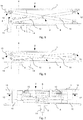
- FIGS. 1 to 12 show the same embodiment of a door handle.
- the door handle is shown in closed position in perspective view.
- the door handle has an actuating element 1, the upper surface of which is designed as an actuating surface 2.
- the actuating surface 2 is flat and square and has a side length of 20 cm.
- the actuating element 1 is connected by an actuating guide 3 with a base body 8.
- door handle of the main body 8 of the door handle is fixed relative to the door leaf 20 and a lock 21 fixed to the door panel 20.
- the actuating element 1 is movably arranged on the door leaf 20 by the actuating guide 3.
- a transmission unit 4 is arranged between the base body 8 and the actuating element 1.
- the transmission unit 4 transmits a movement of the actuating element 1 along a transmission axis 6 into a rotation of a transmission element 5 about the transmission axis 6.
- the transmission element 5 is designed here as a shaft and is non-positively connected to a final nut of the lock 21.
- FIG. 2 shows the same as FIG. 1 , but without the actuator 1.
- the actuating guide 3 comprises two guide elements 10.
- the guide elements 10 both extend substantially in each case from the actuating element 1 to the main body 8 and are both rotatably arranged about the same guide axis of rotation 11.
- the guide axis of rotation 11 is perpendicular to the transmission axis 6.
- the guide elements 10 are respectively connected to the base body 8 on the one hand and with the actuating element 1 on the other.
- the guide elements 10 rotate about the guide axis of rotation 11, and at the same time moves the guide axis of rotation 11 in the same direction as the actuator. 1
- a guide element 10 is only rotatably connected to the base body 8 and rotatably and simultaneously slidably connected to the actuating element 1.
- the other guide element 10 is exactly the other way exclusively rotatably connected to the actuating element 1 and rotatable and at the same time slidably connected to the base body 8.
- the exclusively rotatable connection is designed as a rotatable axle in a bearing enclosing the axle.
- the rotatable and at the same time displaceable along a displacement axis 15 connection is formed as a rotatable axis in the form of a round connecting element which is guided in a linearly leading this axis and in the direction of the displacement axis 15 on one side open gate.
- the gate allows a displacement along the displacement axis 15, which is arranged both perpendicular to the transmission axis 6 and perpendicular to the guide axis of rotation 11. Due to the one-sided openness of the backdrop, the guide elements 10 can be easily attached if necessary or be removed. Both in a closed position and in an open position and all positions in between the axis is guided in the one-sided open backdrop and viewed from the one-sided opening from within the gate.
- the actuating guide 3 has by its construction on an actuating guide track 7, along which the actuating element 1 can be moved from the closed position to the open position.
- the actuating guide track 7 is arranged parallel to the transmission axis 6. The actuating element 1 is thus moved along the direction of the transmission axis 6.
- FIG. 2 is also a fastening device 12 can be seen well, which secures the actuating element 1 to the actuating guide 3.
- the fastening device 12 comprises fastening elements 13 which function as a snap closure.
- the actuating element 1 has in the region of two corners towards the actuating guide 3 formed on one side open link guides, which can be pushed by the one-sided opening via two matching axes (ie two round in cross-section connecting elements) on a guide element 10.
- the actuating element 1 can then be rotated around the round connecting elements in the direction of the other guide element 10 and pushed along the displacement axis 15.
- the other guide element 10 has at its ends the two prestressed fastening elements 13 which are movable parallel to the guide axis of rotation 11.
- FIG. 2 shows the fasteners 13 in the fastened position: the fasteners 13 protrude in a direction parallel to the guide axis of rotation 11 on the fixture 12 and in this way engage in two the mounting elements 13 enclosing bearings on the actuator 1 a (provided an actuator 1 is mounted, such as in FIG FIG. 1 ).
- the engaging in the actuator 1 parts of the fasteners 13 have the function of axes which form in the axes enclosing the bearings of the actuating element 1, the exclusively rotatable connections of the guide member 10 with the actuator 1.
- the fasteners 13 can from their attachment position in FIG. 2 moved against the bias and twisted locked in a Unbeographwolf so that the actuators 13 are located outside the bearings of the actuator 1 and at the same time parts of the fasteners 13 project upwards into an area where the actuator 1 comes to lie in the fixed position.
- the fastening elements 13 are brought into unfastened position and the actuating element 1 as described above with its unilaterally open scenes rotatably and slidably attached to a guide element 10.
- the actuating element 1 is rotated and pushed in the direction of the other guide element 10 and thus in the direction of the fastening elements 13, ie in FIG. 2 to the bottom left.
- the actuator 1 thereby pushes the upwardly projecting parts of the fasteners 13 down, where they are pressed by the bias parallel to the guide axis 11 away from each other in the fastened position and in the correspondingly arranged bearings of the actuator 1.
- the transfer unit 4 has at its upper end a square surface, which is held by the actuating element 1 relative to the transmission axis 6 against rotation.
- the actuating element 1 thus secures a linearly movable component of the transmission unit 4, which comprises the upper square surface, from a rotation about the transmission axis 6.
- FIG. 3 shows the same thing to us FIG. 2 , with the door handle is in the open position.
- the actuating element 1 In closing position as in Figures 1 and 2 shown, the actuating element 1 is further spaced from the base body 8 as in the open position as in FIG. 3 shown.
- the actuating element 1 is only translationally movable from the closed position into the open position.
- FIG. 4 is the same as in FIG. 3 shown, but without actuating control 3.
- FIG. 4 the main body 8 and the transfer unit 4.
- FIG. 5 shows the door handle FIG. 1 , ie in closed position, in a side view.
- FIG. 6 shows the same in the open position.
- the transmission element 5 can be seen, which is designed as a shaft.
- the transmission element 5 rotates about the transmission axis 6 when the actuating element 1 translationally from the closed position in FIG. 5 in the open position in FIG. 6 is moved.
- Good to see in FIGS. 5 and 6 also on the actuator 1 left and bottom formed the bearings of exclusively rotatable connections with the guide member 10 and the bottom formed on one side to the right open scenes of the rotatable and sliding connections with the guide element 10.
- the fasteners 13 protrude in the fastened position to the left away from the fixture 12 out.
- FIG. 7 shows the same as FIG. 6 in front view, so the door handle FIG. 1 in open position.
- the main body 8 has two mounting lugs 14, which in FIGS. 5 and 6 are arranged on the left and right of the transmission element 5 and in FIG. 7 now lie in front of and behind the transmission element 5.
- FIGS. 8 and 9 show only the transmission unit 4 of the door handle FIG. 1 , FIG. 8 shows them in the closed position, FIG. 9 in open position. Also clearly visible in the perspective view is the relative to each other untwisted, exclusively translationally changed position of the square Surface at the upper end of the purely translatory moving part of the transfer unit. Also clearly visible are the relative to each other only about the transmission axis 6 rotated positions of the transmission element 5.
- the transmission unit 4 and the transmission element 5 are non-positively connected to each other via a helical link guide.
- FIG. 10 is the door handle off FIG. 1 shown in plan view.
- plan view is clearly visible, as the fasteners 13 protrude beyond the actuator 1, so that for removing the attached actuator 1, the fasteners 13 can be brought from the mounting position shown in the unfastened position.
- the protrude allows access to the fasteners 13.
- the actuating surface 2 extends over the entire surface of the actuating element 1, which, however, is slightly smaller than the base body 8 is formed.
- the main body 8 protrudes beyond the actuating element 1 as well as beyond the fastening elements 13.
- FIGS. 11 and 12 show a door leaf 20 with built-in door handle FIG. 1 in closed position as well as in open position.
- the actuating surface 2 of the door handle is in the closed position (ie in FIG. 11 ) positioned flush with the door leaf 20. Consequently, the actuating surface 2 is recessed in the open position in the door leaf 20.
- a case of the lock 21 protrudes in the closed position of the actuating element 1 out of the lock 21 and is recessed in the open position of the actuating element 1 in the lock 21.
- FIG. 13 shows an embodiment of the second aspect of the invention: a door locking system with a tension member 32.
- the door locking system comprises a door lock 21 and a door holding member 30.
- the door lock 21 includes a movable in the door lock 21 lock element 31, such as a trap.
- the door holding element 30 differing from the lock element 31 is formed outside the door lock 21 and separately from the door lock 21, here for example at the top arranged at the dotted door leaf 20.
- the door holding element 30 is connected via a tension element 32 with the lock element 31.
- a movement of the lock member 31 from a closed position to an open position causes by the tension member 32 is an analogous movement of the door holding member 30 from a closed position to an open position.
- the tension element 32 is a wire cable which is fastened to the lock element 31, for example on an upwardly projecting driver formed on the lock element 31. About a role deflected the tension element 32 is connected to the door holding member 30. A movement of the lock member 31 in FIG. 13 to the right causes a movement of the door holding member 30 down.
- the door lock 21 can in FIG. 13 be replaced by a door handle described above.
- the tension element 32 is connected to the transmission element 5 of the door handle, either directly or for example via a driver.
- the door locking system may also include both door lock 21 and door handle (especially a door handle formed as described above).
- the tension element 32 may be connected to one or more of the elements described above as an option.
Landscapes
- Engineering & Computer Science (AREA)
- Mechanical Engineering (AREA)
- Lock And Its Accessories (AREA)
Abstract
Description
- Die Erfindung bezieht sich auf das Gebiet der Beschläge für Fenster oder Türen, und insbesondere auf einen Türdrücker zum Öffnen einer Türe, beispielsweise zur Betätigung eines Schlosses.
- Übliche Türdrücker, welche zum Öffnen einer Türe für die Betätigung eines Türschlosses an der Schlosswelle angreifen, sind als Klinken ausgebildet. Solche Türdrücker respektive Türklinken sind aber störend oder gefährlich, wie z. B. im Innern von Sporthallen, wo sie als vorstehende Teile Verletzungen hervorrufen könnten, in Spitälern, wo sie sich an Betten verfangen können, in Aufzügen, Campingbussen oder Pferdeboxen etc. Dies betrifft auch Fluchttüren und/oder Brandtüren, welche beispielsweise in Korridoren und Gängen angeordnet sind und welche in der Regel offenstehen und nur im Notfall schliessen. Und eine Verwendung der üblichen Türklinken in Schiebetüren ist wegen Ihres Überstandes mit Nachteilen verbunden und bedingt komplizierte Türkonstruktionen.
- Türdrücker werden beispielsweise mit Standardschlössern, typischerweise Einsteckschlössern kombiniert, wobei die Bewegungsübertragung respektive Kraftübertragung über einen Vierkant erfolgt, der in eine Drückernuss, einen zentralen, runden Einsatz im Schloss gesteckt wird (im Folgenden wird dafür der Begriff "Schlossnuss" verwendet). Das eingesteckte Schloss sitzt in einer im Türblatt ausgearbeiteten Schlosstasche und ist an einer sog. Stulpe mit dem Türblatt verschraubt. Nach Betätigung des Türdrückers sorgt eine Nussfeder auch Kontrefeder genannt, im Folgenden als Schlossfeder bezeichnen dafür, dass sich Schlossnuss, Vierkant und Türdrücker wieder in die Ausgangsstellung bewegen.
- Türdrücker können auch mit von Türschlössern verschiedenen Türhalteelementen kombiniert werden.
- Ein Türhalteelement ist ein Element, welches ein Türblatt in einem verriegelten geschlossenen Zustand zu halten imstande ist und durch eine Betätigung des Türhalteelements das Türblatt in einen unverriegelten und öffenbaren Zustand zu bringen imstande ist. Mit anderen Worten ist ein Türhalteelement eine öffenbare Verriegelung eines Türblatts. Beispielsweise können Türhalteelemente wie Türfallen ausgebildet sein und an einem oberen und/oder unteren Ende des Türblatts angeordnet sein. Türdrücker können zum Betätigen von Türhalteelementen in Türblättern verwendet werden, welche kein Türschloss umfassen, beispielsweise in Ausführungsformen von Fluchttüren oder Brandtüren ohne Türschloss.
- Übliche Türdrücker sind in verschiedenen Formen verbreitet, beispielsweise als Türklinke, Muschelgriff oder Panikstangen (auch bekannt als "touchbar").
- Die Türklinke und die Panikstange stehen deutlich aus dem Türblatt heraus, manchmal teilweise auch ein Muschelgriff. Dies ist eine potentielle Gefahrenquelle für Verletzungen. Teile der üblichen Türdrücker können auch Gegenstände oder Wände bei Kontakt beschädigen. Je nach Bauweise und Öffnungsrichtung der Türe sind bauliche Anpassungen oder komplizierte Konstruktionen nötig. Auch mit Einschränkungen ist zu rechnen wie etwa eine eingeschränkte maximale Öffnungsweite des Türblatts und/oder ein Mindestabstand des Türblatts von einer Wand in geöffnetem Zustand der Türe.
- Muschelgriffe sind zwar flach ausgebildet und weisen teilweise die obigen Nachteile nicht auf. Aber als Muschelgriff ausgebildete Türdrücker sind kompliziert aufgebaut.
- Die Bedienung von Muschelgriffen ist wie bei anderen Türdrückern manchmal schwierig.
- Die Bedienung der üblichen Türdrücker kann verschiedene Probleme verursachen. Meist ist immer noch eine Drehung, ein Ziehen oder ein Drücken in eine von der Bewegungsrichtung des Türblattes verschiedene Bewegung nötig um den Türdrücker zu bedienen und eine weitere Bewegung, um das Türblatt zu bewegen. Eine Folge von Bewegungen in zwei verschiedene Richtungen (z.B. drehen und drücken oder nach unten und danach nach hinten drücken) ist nicht immer intuitiv klar. Falls zwei verschiedene Bewegungen hintereinander ausgeführt werden müssen, kann eine Türe nur mit geringer Geschwindigkeit geöffnet und/oder geschlossen werden. Weglänge, Richtung, Angewendete Kraft und Abfolge der nötigen Bewegungen zum Bedienen eines der üblichen Türdrücker können stark variieren und sind nicht immer rasch und einfach erkennbar. Die üblichen Türdrücker sind auf Fähigkeiten von Durchschnittsmenschen ausgerichtet. Insbesondere Kinder, Behinderte, ältere und/oder gebrechliche Leute und/oder Menschen in Stresssituationen können Mühe mit dem Bedienen von üblichen Türdrückern bekunden.
- Ein weiterer Nachteil ist eine Möglichkeit von Fehlmanipulationen an bekannten Türdrückern. Beispielsweise können bei im Regelfall offenstehenden Flucht-und/oder Brandtüren bekannte Türdrücker nicht nur wie vorgesehen bedient werden, also arretiert, befestigt, als Halterungen missbraucht, betätigt und/oder sogar beschädigt werden.
- Es ist deshalb Aufgabe der Erfindung, einen Türdrücker der eingangs genannten Art zu schaffen, welche mindestens einen der oben genannten Nachteile mindestens teilweise behebt.
- Diese Aufgabe löst ein Türdrücker zur Betätigung einer vom Türdrücker separat ausgebildeten und um eine Übertragungsachse drehbaren Welle oder Nuss zum Öffnen einer Türe, wobei ein Übertragungselement des Türdrückers um die Übertragungsachse drehbar angeordnet ist und der Türdrücker ein Betätigungselement, eine Betätigungsführung und eine Übertragungseinheit aufweist. Das Betätigungselement umfasst dabei eine Betätigungsfläche, wobei das Betätigungselement durch Krafteinwirkung auf die Betätigungsfläche von einer Schliessstellung in eine Öffnungsstellung bewegbar ist. Dabei ist die Betätigungsfläche sowohl in der Schliessstellung als auch in der Öffnungsstellung jeweils im Wesentlichen normal zur Übertragungsachse angeordnet. Die Betätigungsführung weist eine Betätigungsführungsbahn auf, entlang welcher das Betätigungselement von der Schliessstellung in die Öffnungsstellung bewegbar ist. Die Betätigungsführungsbahn ist parallel zur Übertragungsachse ausgebildet. Und die Übertragungseinheit ist imstande, eine Bewegung des Betätigungselements von der Schliessstellung zur Öffnungsstellung in eine Drehung des Übertragungselements umzusetzen.
- Eine Fläche ist im Wesentlichen normal zu einer Achse angeordnet, wenn eine geglättete Aussenkontur einer Projektion dieser Fläche auf eine die Achse umfassende Ebene nicht mehr als 15 Winkelgrad von einer Senkrechten auf die Achse abweicht. Insbesondere beträgt die Abweichung maximal 10 Winkelgrad. Die Abweichung kann maximal 5 Winkelgrad sein. Mit geglätteter Aussenkontur ist gemeint, dass etwaige Unterbrüche oder kleine Verformungen wie Rippen, Noppen Furchen, Nuten oder Wellen durch entsprechende kurze gerade Verbindungsstücke ersetzt sind.
- Insbesondere ist die Betätigungsfläche sowohl in der Schliessstellung als auch in der Öffnungsstellung jeweils normal zur Übertragungsachse angeordnet.
- Unter Türdrücker wird hier und im Folgenden eine Vorrichtung zum Öffnen einer Türe verstanden, beispielsweise unter Anderem zum Betätigen eines Türhalteelements und/oder eines Schlosses, insbesondere eines Türschlosses oder Fensterschlosses.
- Die Betätigung kann durch Bewegung eines Betätigungselementes gegen den Türdrücker und beispielsweise eine Türe hin, aber auch durch Ziehen eines Betätigungselements vom Türdrücker weg und beispielsweise von einer Türe weg geschehen. Der Einfachheit halber wird in beiden Fällen der Begriff "Drücker" verwendet. Der Begriff "Drücker" umfasst beispielsweise auch Stossplatten, Druckplatten.
- Der Türdrücker kann als "Push"-Variante realisiert sein, welche beim Drücken der Betätigungsplatte gegen den Türdrücker resp. die Tür das Schloss und/oder das Türhalteelement öffnet, oder als "Pull"-Variante, welche beim Ziehen der Betätigungsplatte vom Türdrücker resp. von der Tür weg das Schloss und/oder das Türhalteelement öffnet. Sinnvollerweise werden diese Varianten so eingesetzt, dass die Bewegungsrichtung der Betätigungsplatte der Öffnungsrichtung der Tür entspricht. Eine bevorzugte Kombination von zwei solchen Türdrückern am selben Schloss umfasst also einen "Push-" und einen "Pull"- Türdrücker.
- Die erfindungsgemässen Türdrücker können paarweise eingesetzt werden, oder in Kombination mit einer Türklinke, einer anderen Art von Drücker oder gar keinem Drücker respektive einem Türknauf. Einer oder zwei der Türdrücker können mit einem Schloss mit geteilter Schlossnuss (Panikschloss) eingesetzt werden.
- Beim erfindungsgemässen Türdrücker ist also eine im Wesentlichen normal zur Übertragungsachse angeordnete Betätigungsfläche parallel entlang der Übertragungsachse von der Schliessstellung zu Öffnungsstellung bewegbar. Durch diese Bewegung wird der Türdrücker bedient und beispielsweise das Türblatt in einen bewegbaren Zustand gebracht. Durch Fortführen derselben Bewegung in derselben Richtung, nämlich parallel entlang der Übertragungsachse, kann nun beispielsweise das Türblatt bewegt werden. Die Türe kann also dadurch geöffnet werden - entweder durch Drücken oder durch Ziehen.
- Auf diese Weise ist es möglich, eine Tür durch eine Bewegung in eine einzige Richtung zu öffnen oder zu schliessen. Dies ist einfach und rasch zu erkennen. Eine intuitive Bedienung des Türdrückers und der dazugehörigen Türe ist möglich.
- Beschädigungen und/oder Verletzungen können verhindert oder minimiert werden, da selbst wenn Teile eines solchen Türdrücker aus dem Türblatt herausstehen, diese in Richtung der Übertragungsachse beweglich sind und nachgeben können.
- Die Bewegung der Betätigungsfläche parallel entlang der Übertragungsachse kann mit einer kompakten Bauweise ermöglicht werden. Dadurch kann der Überstand über das Türblatt und damit verbundene Nachteile minimiert oder eliminiert werden. Auf komplizierte Konstruktionen von Türrahmen oder anderen Teilen ausserhalb des Türblattes kann verzichtet werden. Durch die Konstruktion basierend auf einer Bewegung in nur einer Richtung kann der Türdrücker derart ausgebildet werden, dass ein grosser Kreis an Benutzern diesen mühelos bedienen kann.
- Die Bewegung der Betätigungsfläche parallel entlang der Übertragungsachse kann Fehlmanipulationen verhindern oder deren Wahrscheinlichkeit verringern. Eine Bewegung parallel entlang der Übertragungsachse ist in Schliess- oder Öffnungsrichtung der Türe ausgerichtet. Eine Fehlmanipulation des Türdrückers würde also eine Schliess- oder Öffnungsbewegung der Türe bewirken und nicht nur den Türdrücker betreffen, was die Fehlmanipulation rascher erkennbar und verhinderbar macht. Insbesondere bei bis zum Anschlag offenen Türen ist eine Fehlmanipulation schwieriger, weil die Bewegungsrichtung des Türdrückers (entlang der Übertragungsachse) auf der Anschlagseite schlecht bis gar nicht zu bedienen ist.
- Ein weiterer Vorteil der Bewegung der Betätigungsfläche parallel entlang der Übertragungsachse ist die Möglichkeit, eine Grösse und Form der Betätigungsfläche ohne Einschränkung der Funktionalität auf spezifische Anforderungen gezielt auswählen zu können. Wo beispielsweise Klinken nicht beliebig verlängerbar sind und dem Hebelgesetz entsprechend an verschiedenen Angriffspunkten verschiedener Kräfte und Wege zum Bedienen bedürfen, kann die oben beschriebene Betätigungsfläche in verschiedenen Grössen und Formen ausgebildet werden, ohne dass der Weg und/oder die Kraft beim Bedienen je nach Angriffspunkt variiert. Je nach Form, Gewicht, Grösse und/oder anderen Faktoren des Türblatts oder der Türe kann die Betätigungsfläche in Grösse und Form variiert werden, ohne dass die Bedienung ändert.
- Vorteilhaft an der Bewegung der Betätigungsfläche parallel entlang der Übertragungsachse ist, dass die Betätigungsfläche an einem beliebigen Angriffspunkt in Richtung der Übertragungsachse betätigt werden kann. Der Türdrücker kann also oben, unten, recht, links, mittig und in allen Kombinationen davon auf der Betätigungsfläche bedient werden. Im Gegensatz dazu variieren je nach Angriffspunkt Kraft, Weg und eine Möglichkeit der Bedienbarkeit überhaupt bei Türdrückern, welche eine Kipp-, Dreh- und/oder eine Translationsbewegung nicht parallel zur Übertragungsachsenrichtung (also zur Türblattöffnungsrichtung bzw. - schliessrichtung) aufweisen.
- Weitere bevorzugte Ausführungsformen gehen aus den abhängigen Patentansprüchen hervor. Die Merkmale der Ausführungsformen können miteinander kombiniert sein.
- In einer Ausführungsform weist das Übertragungselement einen vorstehenden Vierkant auf, der in die Schlossnuss eines Schlosses einsteckbar. Damit ist es möglich, den Türdrücker ohne Verwendung weiterer Teile mit einem Schloss zu kombinieren.
- In einer Ausführungsform ist das Übertragungselement eine Betätigungsnuss, in welche eine als Vierkant ausgebildete Schlosswelle einsteckbar ist.
- Damit ist es möglich, eine herkömmliche Schlosswelle auf einer Seite in den Türdrücker, durch ein herkömmliches Schloss und auf der anderen Seite in einen gleichartig oder anders gestalteten Türdrücker zu stecken. Der Länge der Schlosswelle kann entsprechend der Dicke der Türe gewählt werden.
- In einer Ausführungsform ist die Betätigungsführung derart ausgebildet, dass das Betätigungselement ausschliesslich translatorisch entlang der Betätigungsführungsbahn bewegbar ist.
- Eine rein translatorische Bewegung des Betätigungselements von der Öffnungsstellung zur Schliessstellung und/oder umgekehrt ist vorteilhaft, wenn zum Beispiel zum Bewegen des Türblatts ebenfalls eine ausschliesslich translatorische Kraft nötig ist. Auch ist eine Bedienung des Türdrückers einfach und angenehm, wenn nur eine Bewegungsrichtung bei der Bedienung des Türdrückers auf die Hand oder ein anderes bedienendes Element wirkt.
- Alternativ kann das Betätigungselement beispielsweise auch eine Kombination einer translatorischen und rotatorischen Bewegung sein. Auch andere Bewegungen können mit der Translationsbewegung kombiniert werden. Das Betätigungselement kann auf dem Weg von der Öffnungsstellung zu Schliessstellung und/oder zurück auch zeitweise nicht normal zur Übertragungsachse ausgerichtet sein. Beispielsweise kann das Betätigungselement zwischen diesen Stellungen verkippt sein.
- In einer Ausführungsform des Türdrückers umfasst die Betätigungsfläche eine durchgehend ebene Fläche, welche mindestens 100 Quadratzentimeter gross ist. Insbesondere ist die ebene Fläche mindestens 225 Quadratzentimeter gross. Insbesondere ist die ebene Fläche mindestens 400 Quadratzentimeter gross.
- Eine Betätigungsfläche mit einer durchgehend ebenen Fläche einer Mindestgrösse ist einfach und risikoarm bedienbar. Von einer ebenen Fläche geht wenig Gefahr eines Hängenbleibens oder einer Verletzung aus. Eine ebene Fläche ist einfach und kostengünstig herstellbar. Ebene Flächen sind einfach zu reinigen. Eine ebene Betätigungsfläche kann einen Überstand des Türdrückers über das Türblatt trotz grosser Bedienungsfläche gering halten, weil etwa der Überstand durch die gesamte ebene Fläche maximal ausgenutzt ist.
- Alternativ kann die Betätigungsfläche durchbrochene Flächen aufweisen. Die Betätigungsfläche kann etwa gebogen, gekrümmt und/oder gewellt ausgebildet sein. Die Betätigungsfläche kann auch asymmetrisch ausgebildet sein - entlang und/oder quer zur Übertragungsachse. Die Form, Grösse und/oder Oberflächenbeschaffenheit der Betätigungsfläche kann frei gewählt werden.
- In einer Ausführungsform umfasst die Betätigungsführung mindestens zwei Führungselemente, welche um eine Führungsdrehachse drehbar angeordnet sind. Dabei ist die Führungsdrehachse senkrecht zur Übertragungsachse angeordnet.
- Eine Anordnung der Führungsachse, um welche sich Führungselemente der Betätigungsführung drehen können, senkrecht zur Übertragungsachse erlaubt eine platzsparende Konstruktion in Richtung der Übertragungsachse. Also ist eine flache Bauweise ermöglicht.
- Alternativ kann die Führungsdrehachse auch schräg zur Übertragungsachse angeordnet sein. Oder aber auch parallel.
- Insbesondere sind die Führungselemente jeweils drehsymmetrisch um die Führungsdrehachse angeordnet. Mit anderen Worten ist die Führungsdrehachse mittig in den Führungselementen angeordnet. Dies erlaubt eine einfache Konstruktion des Türdrückers. Eine gleichmässige Verteilung von Kräften und Belastungen auf die Führungselemente wird dadurch auch ermöglicht.
- Die Führungsdrehachse kann aber auch an anderen Stellen als der Mitte der Führungselemente angeordnet sein.
- In einer Ausführungsform ist die Führungsdrehachse durch die Bewegung des Betätigungselements von der Schliessstellung zur Öffnungsstellung in dieselbe Richtung verschiebbar.
- Bei einem Mitbewegen der Führungsdrehachse in dieselbe Richtung wie das Betätigungselement kann Platz gespart werden. Dies erlaubt eine in Übertragungsachsrichtung kompakte und flache Bauweise des Türdrückers.
- Alternativ kann die Führungsdrehachse auch ortsfest ausgebildet sein. Oder die Führungsdrehachse kann in eine andere Richtung als das Betätigungselement bewegt werden, beispielsweise quer dazu oder entgegengesetzt. Die Führungsdrehachse kann sich beispielsweise auch drehen.
- In einer Ausführungsform erstrecken sich die Führungselemente im Wesentlichen jeweils vom Betätigungselement zu einem Grundkörper des Türdrückers.
- Der Grundkörper des Türdrückers ist ein Element des Türdrückers, welches in eingebautem Zustand des Türdrückers in dem Türblatt relativ zum Türblatt ortsfest ist, insbesondere bei einer Bedienung des Türdrückers. Somit wird bei der Bewegung des Betätigungselements von der Öffnungsstellung zur Schliessstellung und/oder umgekehrt das Betätigungselement relativ zum Grundkörper des Türdrückers bewegt.
- Die Führungselemente erstrecken sich im Wesentlichen vom Betätigungselement zum Grundkörper, wenn sich die Führungselemente in Projektion auf eine die Übertragungsachse umfassende Ebene über mindestens 80% des Abstandes zwischen Kraftübertragungspunkten der Führungselemente auf dem Betätigungselement und Kraftübertragungspunkten der Führungselemente auf dem Grundkörper in dieser Projektion erstrecken. Insbesondere erstreckt sich das Führungselement in der Projektion über 90% des Abstandes. Das Führungselement kann sich in der Projektion über 95% des Abstandes erstrecken.
- Mit Kraftübertragungspunkten sind diejenigen Punkte gemeint, an welchen eine von den Führungselementen auf das Betätigungselement oder den Grundkörper ausgeübte Kraft ansetzt. Beispielsweise etwa direkte Verbindungspunkte an einer Drehverbindung zwischen Führungselement und Betätigungselement oder Grundkörper. Oder aber eine kraftschlüssige Verbindungsstelle eines Verbindungselements von Führungselement und Betätigungselement beziehungsweise Grundkörper.
- Erstrecken sich die Führungselemente im Wesentlichen vom Betätigungselement zum Grundkörper, kann die Betätigungsführung mit wenigen Elementen einfach und kostengünstig ausgebildet werden. Herstellung, Wartung, Reparatur und Kontrolle können rasch erfolgen und kostengünstig ausgeführt werden.
- Insbesondere erstrecken sich die Führungselemente jeweils vom Betätigungselement zu einem Grundkörper des Türdrückers.
- Alternativ können die Führungselemente kürzer sein als der Abstand zwischen dem Betätigungselement und dem Grundkörper des Türdrückers.
- Insbesondere erstrecken sich die Führungselemente in Projektion auf eine die Übertragungsachse umfassende Ebene nicht über das Betätigungselement des Türdrückers hinaus.
- Insbesondere erstrecken sich die Führungselemente in Projektion auf eine die Übertragungsachse umfassende Ebene nicht über den Grundkörper des Türdrückers hinaus.
- In einer Ausführungsform weisen die Führungselemente jeweils eine erste Verbindung mit dem Betätigungselement und eine zweite Verbindung mit dem Grundkörper aufweisen, wobei entweder
- die erste Verbindung für eine ausschliesslich drehbare Bewegung um eine Achse parallel zur Führungsdrehachse ausgebildet ist und die zweite Verbindung für gleichzeitig sowohl eine Drehung um eine Achse parallel zur Führungsdrehachse als auch für eine Verschiebung des Führungselements relativ zum Grundkörper entlang einer Verschiebungsachse ausgebildet ist, und die Verschiebungsachse sowohl senkrecht zur Führungsdrehachse als auch senkrecht zur Übertragungsachse angeordnet ist, oder
- die erste Verbindung für gleichzeitig sowohl eine Drehung um eine Achse parallel zur Führungsdrehachse als auch für eine Verschiebung des Führungselements relativ zum Betätigungselement entlang einer Verschiebungsachse ausgebildet ist, und die Verschiebungsachse sowohl senkrecht zur Führungsdrehachse als auch senkrecht zur Übertragungsachse angeordnet ist, und die zweite Verbindung für eine ausschliesslich drehbare Bewegung um eine Achse parallel zur Führungsdrehachse ausgebildet ist.
- Mit anderen Worten ist jeweils ein Ende eines Führungselements nur drehbar, das andere drehbar und gleichzeitig auch verschiebbar befestigt. Die gleichzeitige Drehbarkeit und Verschiebbarkeit kann etwa durch ein rundes Verbindungselement geführt in einer Kulisse ausgebildet werden. Das runde Verbindungselement kann um seine Symmetrieachse drehen und gleichzeitig entlang der Kulisse verschoben werden.
- Diese Ausführungsform mit einer Kombination einer reinen Drehverbindung und einer kombinierten Dreh- und Verschiebeverbindung ist kostengünstig und einfach realisierbar. Sie ist robust und wenig störanfällig.
- Insbesondere kann die Verschiebungsachse schräg zur Führungsdrehachse und/oder schräg zur Übertragungsachse angeordnet sein.
- Alternativ kann ein Führungselement auch an beiden Seiten eine kombinierte Dreh-und Verschiebeverbindung aufweisen. Oder ein Führungselement weist beispielsweise an beiden Seiten eine reine Drehverbindung auf. Auch elastische Verbindungen oder mindestens teilweise elastische Führungselemente können an Stelle mindestens einer der vorgenannten Verbindungen eingesetzt sein.
- In einer Ausführungsform weist mindestens ein erstes Führungselement die erste Verbindung für die ausschliesslich drehbare Bewegung um eine Achse parallel zur Führungsdrehachse auf und mindestens ein zweites Führungselement die zweite Verbindung für die ausschliesslich drehbare Bewegung um eine Achse parallel zur Führungsdrehachse.
- Anders ausgedrückt ist mindestens ein Führungselement ausschliesslich drehbar mit dem Betätigungselement verbunden, und mindestens ein anderes Führungselement ausschliesslich drehbar mit dem Grundkörper.
- Insbesondere ist die ausschliesslich drehbare Verbindung als eine stetige Verbindung zwischen Führungselement und Betätigungselement beziehungsweise Grundkörper ausbildet.
- Mit stetiger Verbindung ist eine Verbindung gemeint, welche zwei Elemente miteinander verbindet und eine Trennung der beiden Elemente voneinander verhindert. Beispielsweise kann die ausschliesslich drehbare Verbindung eine Welle in einer die Welle umschliessenden Halterung umfassen. Dadurch können die durch diese ausschliesslich drehbare Verbindung verbundenen Elemente relativ zueinander gedreht werden, aber nicht voneinander getrennt werden.
- Vorteil einer Ausführungsform mit einem ersten Führungselement mit einer ausschliesslich drehbaren und stetigen Verbindung mit dem Betätigungselement und einem zweiten Führungselement mit einer drehbaren und gleichzeitig verschiebbaren und stetigen Verbindung mit dem Führungselement ist, dass das Betätigungselement relativ zum Grundkörper nur noch entlang der Übertragungsachse bewegbar ist. Da die beiden Führungselemente um dieselbe Führungsdrehachse drehbar sind und dadurch aneinander gekoppelt sind und die ausschliesslich drehbaren und stetigen Verbindungen diese wiederum an Betätigungselement und Grundkörper koppeln, sind Betätigungselement und Grundkörper miteinander verbunden. Die ausschliesslich drehbaren und stetigen Verbindungen stellen in Kombination mit den drehbaren und gleichzeitig auch verschiebbaren Verbindung sicher, dass das Betätigungselement nur entlang der Übertragungsachse relativ zum Grundkörper bewegbar ist.
- Insbesondere ist die drehbare und gleichzeitig auch verschiebbare Verbindung als eine stetige Verbindung zwischen Führungselement und Betätigungselement beziehungsweise Grundkörper ausbildet.
- Alternativ ist die ausschliesslich drehbare Verbindung und/oder die drehbare und gleichzeitig auch verschiebbare Verbindung als trennbare Verbindung ausgebildet.
- Führungselemente können auch auf derselben Seite die ausschliesslich drehbare Verbindung aufweisen, beispielsweise am Grundkörper.
- In einer Ausführungsform weist die Betätigungsführung eine Befestigungsvorrichtung für das Betätigungselement auf. Dabei weist die Befestigungsvorrichtung mindestens ein Befestigungselement auf, welches in einer Unbefestigtstellung der Befestigungsvorrichtung in einen Raumbereich um die Betätigungsführung hineinragt, welcher vom Betätigungselement in einer Befestigtstellung der Befestigungsvorrichtung eingenommen wird. Dabei ist in der Unbefestigtstellung das Betätigungselement von der Befestigungsvorrichtung und dadurch von der Betätigungsführung entfernt. Und in der Befestigtstellung ist das Betätigungselement an der Befestigungsvorrichtung und dadurch an der Betätigungsführung befestigt.
- Eine solche Ausführungsform kann in Form eines Schnappverschlusses für das Betätigungselement ausgebildet sein. Dabei ragt das Befestigungselement über die Betätigungsführung hinaus und wird beim Befestigen des Betätigungselements an der Betätigungsführung vom Betätigungselement weggedrückt. Diese Bewegung kann einen Schnappmechanismus auslösen, welche das Betätigungselement an der Betätigungsführung befestigt.
- Ein Befestigungselement, welches durch das Betätigungselement bei einer Befestigung desselben verdrängt wird, erlaubt eine einfache, rasche und sichere Befestigung des Betätigungelements an der Betätigungsführung. Dadurch ist eine einfache, rasche, sichere und intuitive Montage des Türdrückers möglich.
- Die Betätigungsführung kann aber auch ohne Betätigungselement und insbesonder auch ohne Befestigungsvorrichtung für das Betätigungselement ausgebildet sein.
- In einer Ausführungsform ragt das mindestens eine Befestigungselement in der Befestigtstellung in Projektion auf die Betätigungsfläche über eine Aussenkontur einer Projektion des Betätigungselements auf die Betätigungsfläche hinaus.
- Durch ein Hinausragen oder Überstehen des Befestigungselements über das Betätigungselement kann einfach auf das Befestigungselement zugegriffen werden. Dies ermöglicht ein einfaches und rasches Bedienen der Befestigungsvorrichtung und insbesonder ein einfaches und rasches Öffnen der Befestigungsvorrichtung. Das Betätigungselement kann unkompliziert und schnell von der Betätigungsführung und damit vom Türdrücker gelöst und entfernt werden. Insbesondre ist ein Schnappverschlusses für das Betätigungselement einfach und rasch lösbar. Das Befestigungselement kann in der Befestigtstellung über das Betätigungselement hinausragen aber innerhalb des Türdrückers angeordnet sein.
- Alternativ ist das mindestens eine Befestigungselement in der Befestigtstellung in Projektion auf die Betätigungsfläche von der Aussenkontur einer Projektion des Betätigungselements auf die Betätigungsfläche umgeben.
- In einer Ausführungsform Türdrücker ist der Türdrücker derart ausgebildet ist, dass er durch die Bewegung des Betätigungselements von der Schliessstellung in die Öffnungsstellung auf die Schlosswelle oder Schlossnuss ein Drehmoment von mindestens 5Nm, insbesondere von mindestens 10Nm und insbesondere von mindestens 20Nm auszuüben imstande ist.
- Der Türdrücker weist demnach Komponenten und Elemente von einer Stabilität auf, welche ein Mindestdrehmoment über das Betätigungselement auf die Schlosswelle oder die Schlossnuss zu übertragen imstande sind. Dies erlaubt einen Einsatz des Türdrückers in Kombination mit Türschlössern in robusten und widerstandsfähigen Türen, beispielsweise Zimmer-, Wohnungs- und Haustüren. Auch Notfalltüren oder Zugangstüren zu Gebäuden, Türen in Zäunen und Mauern, Türe in Zügen und Schiffen können mit diesem Türdrücker ausgerüstet werden.
- Alternativ kann der Türdrücker auch ausgebildet sein, ohne dass ein bestimmtes Mindestdrehmoment übertragbar ist.
- In einer Ausführungsform ist der Türdrücker derart ausgebildet, dass auf das Betätigungselement in der Schliessstellung in Richtung von der Öffnungsstellung in die Schliessstellung entlang der Übertragungsachse eine Kraft von maximal 50N wirkt.
- Durch ein Entgegenwirken der Maximalkraft von 50N beim Bedienen bzw. Betätigen des Türdrückers (also der Bewegung von der Schliessstellung in die Öffnungsstellung) ist der Türdrücker einfach und mit wenig Kraftaufwand bedienbar. Zudem erfüllt der Türdrücker damit eine Norm für Türdrücker für Notfalltüren.
- In einer Ausführungsform Türdrücker sind die Übertragungseinheit und das Übertragungselement über eine helikoidale Kulissenführung kraftschlüssig miteinander verbunden. Dabei begrenzt die helikoidale Kulissenführung eine Drehung des Übertragungselements um die Übertragungsachse herum auf maximal 60 Winkelgrad. Insbesondere ist die Drehung auf maximal 45 Winkelgrad begrenzt, und insbesondere auf maximal 30 Winkelgrad begrenzt.
- Eine helikoidale Kulissenführung ist ein effizientes und einfaches und kostengünstiges Mittel zum Umsetzung einer Translation in eine Rotation. Die Kulissenführung kann durch eine Begrenzung des Weges in der Kulissenführung, beispielsweise durch einen entsprechend kurz ausgebildeten Führungskanal und/oder durch einen Anschlag, die maximale Drehung einfach, robust und zuverlässig begrenzen.
- Alternativ kann die helikoidale Führung die maximale Drehung unbegrenzt erlauben. Auf eine helikoidale Führung kann auch verzichtet werden.
- In einer Ausführungsform beträgt ein Mindestweg des Betätigungselements von der Schliessstellung zur Öffnungsstellung mindestens 12mm. Insbesondere beträgt der Mindestweg mindestens 18mm, und insbesondere mindestens 25mm.
- In einer Ausführungsform beträgt ein Maximalweg des Betätigungselements von Schliessstellung zur Öffnungsstellung maximal 30mm. Insbesondere beträgt der Maximalweg maximal 40mm, und insbesondere maximal 50mm.
- Durch eine Begrenzung des Maximalwegs kann der Türdrücker flach und kompakt ausgebildet werden. Solche Türdrücker können platzsparend und insbesondere ganz versenkt in das Türblatt eingebaut werden.
- In einer Ausführungsform ist eine maximale Ausdehnung des Betätigungselementes in Projektion auf die Betätigungsfläche mindestens um einen Faktor 2 grösser als eine maximale Ausdehnung des Türdrückers entlang der Übertragungsachse. Insbesondere ist die maximale Ausdehnung des Betätigungselements in Projektion auf die Betätigungsfläche mindestens um einen Faktor 4 grösser als die maximale Ausdehnung des Türdrückers entlang der entlang der Übertragungsachse, und insbesondere mindestens um einen Faktor 6 grösser.
- Mit maximaler Ausdehnung ist eine eindimensionale Ausdehnung gemeint, also etwa eine Länge einer Diagonale in einem Viereck oder ein Durchmesser eines Kreises.
- Ein mehr breiter als hoher Türdrücker ist flach und kompakt ausgebildet, wodurch ein solcher Türdrücker platzsparend und insbesondere ganz versenkt in das Türblatt eingebaut werden kann.
- Optional umfasst der Türdrücker ein fluoreszierendes oder phosphoreszierendes Element.
- Insbesondere ist dieses Element am Betätigungselement befestigt und/oder ist mindestens ein Teil des Betätigungselements. Dieses Element kann etwa an der Betätigungsfläche befestigt oder als solche ausgebildet sein. Dasselbe gilt für die Stirnflächen des Betätigungselements. Und/oder dieses Element ist beispielsweise am Grundkörper des Türdrückers befestigt und/oder ist mindestens ein Teil des Grundkörpers.
- Dieses Element kann beispielsweise eine Beschichtung, insbesondere eine Lackierung oder ein Aufkleber sein. Der Türdrücker kann auch frei von einem fluoreszierenden oder phosphoreszierenden Element sein.
- In einer Ausführungsform ist die Betätigungsnuss zur Übertragung einer Bewegung auf einen eingesteckten Vierkant mit einem Spiel ausgebildet, insbesondere mit einem Spiel um einen Winkel von 20° bis 50°, insbesondere 25° bis 40°.
- Wenn in dieser Weise ein Spiel zwischen Vierkant und Betätigungsnuss vorliegt, und keine Kompensationseinheit vorliegt (welche die Übertragungseinheit gegen die Schlossfeder in Öffnungsrichtung ziehen würde), wird die Übertragungseinheit nicht bewegt, falls das Schloss durch den gegenüberliegenden Drücker betätigt wird. In diesem Fall kann auf das Spiel zwischen Übertragungseinheit und Betätigungseinheit verzichtet werden. Von der Kinematik her bewegen sich diese beiden Einheiten also wie eine Einheit und, eine Abgrenzung zwischen den beiden ist nicht erforderlich. Beide Einheiten können gemeinsam durch die Betätigungsfeder in die Richtung der Schliessstellung gezogen werden. Diese Ausführungsform ist besonders zur Verwendung mit einem modifizieren Schloss geeignet, bei welchem die Kraft der Schlossfeder gegenüber der Verwendung mit einer Türklinke reduziert ist. Das Spiel zwischen Schloss und Türdrücker, welches Bewegungen im Türdrücker minimiert, findet also bereits in der Betätigungsnuss statt.
- Die Betätigungsnuss kann auch ohne Spiel ausgebildet sein.
- Die Erfindung umfasst auch ein Türblatt mit einem wie oben beschriebenen Türdrücker. Dabei weist der Türdrücker und insbesondere die Betätigungsfläche - bei eingebautem Zustand des Türdrückers - über eine Vorderseite oder eine Hinterseite des Türblatts einen maximalen Überstand von 3mm auf. Insbesondere weist der Türdrücker (und insbesondere die Betätigungsfläche) einen maximalen Überstand von 1.5mm auf. Insbesondere weist der Türdrücker (und insbesondere die Betätigungsfläche) einen maximalen Überstand von 0mm auf - also mit anderen Worten keinen Überstand.
- Das Türblatt mit dem Türdrücker kann ein Türschloss umfassen, welches durch den Türdrücker betätigbar ist. Das Türblatt mit dem Türdrücker ist optional frei von einem Türschloss ausgebildet und umfasst insbesondere mindestens ein Türhalteelement, welches durch den Türdrücker betätigbar ist.
- Ohne Überstand ist der Türdrücker bündig und/oder versenkt im Türblatt eingebaut.
- Der Türdrücker kann auch mit einem Überstand von mehr als maximal 3mm eingebaut sein.
- Ein zweiter Aspekt der Erfindung betrifft ein Türschliesssystem, welches ein Türschloss und/oder einen Türdrücker und mindestens ein Türhalteelement umfasst. Dabei umfasst das Türschloss ein im Türschloss bewegliches Schlosselement, und/oder der Türdrücker umfasst ein Übertragungselement. Das sich vom Schlosselement und dem Türdrücker unterscheidende Türhalteelement ist ausserhalb des Türschlosses und des Türdrückers und separat vom Türschloss und vom Türdrücker ausgebildet. Das Türhalteelement ist dabei über ein flexibles Zugelement, insbesondere über einen Drahtzug, mit dem Schlosselement und/oder dem Übertragungselement verbunden, damit bei einer Bewegung des Schlosselements beziehungsweise dem Übertragungselement von einer Schliessstellung in eine Öffnungsstellung das Türhalteelement eine analoge Bewegung von einer Schliessstellung in eine Öffnungsstellung bewirken kann.
- Insbesondere ist der Türdrücker im Türschliesssystem als Türdrücker wie weiter oben beschrieben ausgebildet.
- Das flexible Zugelement kann ein Drahtzug sein und/oder etwa ein Seil. Das flexible Zugelement ist insbesondere mindestens teilweise ein Strang aus künstlichen oder natürlichen Fasern.
- Die bekannten Metallstangen weisen insbesondere bei längeren Distanzen zwischen Türhalteelement und Schlosselement beziehungsweise Übertragungselement ein Eigengewicht auf, welches auf das Schlosselement beziehungsweise den Türdrücker wirkt. Damit ein Türschliesssystem mit den üblichen auf den Türdrücker anzuwendenden Kräften bedienbar ist, muss je nach auf das Schlosselement beziehungsweise Übertragungselement wirkenden Kraft eine Vorspannung beziehungsweise eine Federstärke des Türschlosses (beziehungsweise des Übertragungselements) berechnet, angepasst und somit einzeln konfektioniert werden.
- Das flexible Zugelement unterscheidet sich von in den üblichen Türschliesssystemen verwendeten starren Metallstangen dadurch, dass sie einerseits flexibel sind und andererseits ein vergleichsweise geringes Gewicht aufweisen.
- Durch das vergleichsweise geringe Gewicht kann immer dieselbe Feder und dasselbe Türschloss beziehungsweise derselbe Türdrücker verwendet werden. Dies vereinfacht Herstellung, Montage und Wartung des Türschliesssystems, weil keine angepassten und spezifischen Teile nötig sind. Auch die Lagerhaltung für Ersatzteile ist viel einfacher, und die nötigen Ersatzteile sind in jeweils grösseren Mengen und dadurch günstiger herstellbar und auch besser verfügbar weil jedes Ersatzteil passt.
- Die Flexibilität des Zugelements erlaubt eine Führung und Umlenkung und dadurch Weiterleitung von Zugkräften auf einfache Weise. Wo Metallstangen komplizierte Formen und Umlenkmechanismen benötigen, können flexible Zugelemente einfach und effizient gekrümmt geführt werden.
- In einer Ausführungsform ist das Schlosselement ein Schlossriegel.
- In einer anderen Ausführungsform ist das Schlosselement eine Falle.
- In einer weiteren Ausführungsform ist das Schlosselement eine Schlosswelle.
- In einer Ausführungsform ist das Schlosselement eine Schlossnuss.
- Die oben genannten Ausführungsformen können untereinander auch kombiniert werden.
- Im Folgenden wird der Erfindungsgegenstand anhand von bevorzugten Ausführungsbeispielen, welche in den beiliegenden Zeichnungen dargestellt sind, näher erläutert. Es zeigen jeweils schematisch:
- Figur 1
- einen Türdrücker in Schliessstellung in perspektivischer Darstellung;
- Figur 2
-
Figur 1 ohne das Betätigungselement; - Figur 3
-
Figur 2 in Öffnungsstellung; - Figur 4
-
Figur 3 ohne Betätigungsführung; - Figur 5
-
Figur 1 in einer Seitenansicht; - Figur 6
-
Figur 5 in Öffnungsstellung; - Figur 7
-
Figur 6 in Frontansicht; - Figur 8
- die Übertragungseinheit aus
Figur 1 in Schliessstellung; - Figur 9
- die Übertragungseinheit aus
Figur 1 in Öffnungsstellung; - Figur 10
- den Türdrücker aus
Figur 1 in Draufsicht; - Figur 11
- ein Türblatt mit eingebautem Türdrücker aus
Figur 1 in Schliessstellung; - Figur 12
-
Figur 12 in Öffnungsstellung; - Figur 13
- ein Ausführungsbeispiel eines Türschliesssystems mit einem Türschloss und einem Zugelement.
- Die in den Zeichnungen verwendeten Bezugszeichen und deren Bedeutung sind in der Bezugszeichenliste zusammengefasst aufgelistet. Grundsätzlich sind in den Figuren gleiche Teile mit gleichen Bezugszeichen versehen. Richtungsangaben zu den Figuren (oben, unten, rechts, links) beziehen sich auf die Druckebene der Figur, z.B. bedeutet also "oben" in Richtung des oberen Randes des Papiers, auf welchem die Figur gedruckt ist.
- Die
Figuren 1 bis 12 zeigen dieselbe Ausführungsform eines Türdrückers. InFigur 1 ist der Türdrücker in Schliessstellung in perspektivischer Darstellung gezeichnet. Der Türdrücker weist ein Betätigungselement 1 auf, dessen obere Oberfläche als Betätigungsfläche 2 ausgebildet ist. Die Betätigungsfläche 2 ist eben und quadratisch ausgebildet und weist eine Seitenlänge von 20 cm auf. - Das Betätigungselement 1 ist durch eine Betätigungsführung 3 mit einem Grundkörper 8 verbunden. Bei in einem Türblatt 20 eingebauten Türdrücker ist der Grundkörper 8 des Türdrückers relativ zum Türblatt 20 und zu einem Schloss 21 ortsfest am Türblatt 20 befestigt. Das Betätigungselement 1 hingegen ist durch die Betätigungsführung 3 beweglich am Türblatt 20 angeordnet. Zwischen dem Grundkörper 8 und dem Betätigungselement 1 ist eine Übertragungseinheit 4 angeordnet. Die Übertragungseinheit 4 überträgt eine Bewegung des Betätigungselements 1 entlang einer Übertragungsachse 6 in eine Rotation eines Übertragungselements 5 um die Übertragungsachse 6. Das Übertragungselement 5 ist hier als Welle ausgebildet und ist kraftschlüssig mit einer Schlussnuss des Schlosses 21 verbunden.
-
Figur 2 zeigt dasselbe wieFigur 1 , allerdings ohne das Betätigungselement 1. InFigur 2 ist klarer erkennbar, dass die Betätigungsführung 3 zwei Führungselemente 10 umfasst. Die Führungselemente 10 erstrecken sich beide im Wesentlichen jeweils vom Betätigungselement 1 zum Grundkörper 8 und sind beide um dieselbe Führungsdrehachse 11 drehbar angeordnet. Die Führungsdrehachse 11 steht dabei senkrecht zur Übertragungsachse 6. Die Führungselemente 10 sind jeweils mit dem Grundkörper 8 einerseits und mit dem Betätigungselement 1 andererseits verbunden. Durch eine Bewegung des Betätigungselement 1 entlang der Übertragungsachse 6 drehen sich die Führungselemente 10 um die Führungsdrehachse 11, und gleichzeitig bewegt sich die Führungsdrehachse 11 in dieselbe Richtung wie das Betätigungselement 1. - Um diese Bewegung des Betätigungselements 1 zu führen, ist ein Führungselement 10 ausschliesslich drehbar mit dem Grundkörper 8 und drehbar sowie gleichzeitig verschiebbar mit dem Betätigungselement 1 verbunden. Das andere Führungselement 10 ist genau umgekehrt ausschliesslich drehbar mit dem Betätigungselement 1 und drehbar und sowie gleichzeitig verschiebbar mit dem Grundkörper 8 verbunden.
- Die ausschliesslich drehbare Verbindung ist als eine drehbare Achse in einer die Achse umschliessenden Lagerung ausgebildet. Die drehbare sowie gleichzeitig entlang einer Verschiebungsachse 15 verschiebbare Verbindung ist als drehbare Achse in Form eines runden Verbindungselements ausgebildet, welche in einer diese Achse linear führenden und in Richtung der Verschiebungsachse 15 einseitig offenen Kulisse geführt ist. Die Kulisse erlaubt eine Verschiebung entlang der Verschiebungsachse 15, welche sowohl senkrecht zur Übertragungsachse 6 als auch senkrecht zur Führungsdrehachse 11 angeordnet ist. Durch die einseitige Offenheit der Kulisse können die Führungselemente 10 bei Bedarf einfach befestigt oder entfernt werden. Sowohl in einer Schliessstellung als auch in einer Öffnungsstellung und allen Positionen dazwischen ist die Achse in der einseitig offenen Kulisse geführt und von der einseitigen Öffnung aus betrachtet innerhalb der Kulisse angeordnet.
- Die Betätigungsführung 3 weist durch seine Konstruktion eine Betätigungsführungsbahn 7 auf, entlang welcher das Betätigungselement 1 von der Schliessstellung in die Öffnungsstellung bewegt werden kann. Die Betätigungsführungsbahn 7 ist parallel zur Übertragungsachse 6 angeordnet. Das Betätigungselement 1 wird also entlang der Richtung der Übertragungsachse 6 bewegt.
- In
Figur 2 ist auch eine Befestigungsvorrichtung 12 gut zu erkennen, welche das Betätigungselement 1 an der Betätigungsführung 3 befestigt. Die Befestigungsvorrichtung 12 umfasst Befestigungselemente 13, welche als Schnappverschluss funktionieren. Das Betätigungselement 1 weist im Bereich von zwei Ecken hin zur Betätigungsführung 3 ausgebildete einseitig offene Kulissenführungen auf, welche durch die einseitige Öffnung über zwei passende Achsen (also zwei im Querschnitt runde Verbindungselemente) an einem Führungselement 10 geschoben werden können. Das Betätigungselement 1 kann dann um die runden Verbindungselemente in Richtung des anderen Führungselements 10 gedreht und entlang der Verschiebungsachse 15 geschoben werden. Das andere Führungselement 10 weist an seinen Enden die zwei vorgespannten Befestigungselemente 13 auf, welche parallel zur Führungsdrehachse 11 bewegbar sind. -
Figur 2 zeigt die Befestigungselemente 13 in Befestigtstellung: die Befestigungselemente 13 ragen in einer Richtung parallel zur Führungsdrehachse 11 über die Befestigungsvorrichtung 12 hinaus und greifen auf diese Weise in zwei die Befestigungselemente 13 umschliessenden Lagerungen am Betätigungselement 1 ein (sofern ein Betätigungselement 1 montiert ist, wie etwa inFigur 1 ). Die in das Betätigungselement 1 eingreifenden Teile der Befestigungselemente 13 haben die Funktion von Achsen, welche in der die Achsen umschliessenden Lagerungen des Betätigungselements 1 die ausschliesslich drehbaren Verbindungen des Führungselements 10 mit dem Betätigungselement 1 ausbilden. - Die Befestigungselemente 13 können aus Ihrer Befestigtstellung in
Figur 2 gegen die Vorspannung bewegt und verdreht in einer Unbefestigtstellung arretiert werden, so dass die Betätigungselemente 13 ausserhalb der Lagerungen des Betätigungselements 1 angeordnet sind und gleichzeitig Teile der Befestigungselemente 13 nach oben in einen Bereich abstehen, wo das Betätigungselement 1 in Befestigtstellung zu liegen kommt. Um das Betätigungselement 1 nun an der Betätigungsführung 3 zu befestigen, werden die Befestigungselemente 13 in Unbefestigtstellung gebracht und das Betätigungselement 1 wie oben beschrieben mit seinen einseitig offenen Kulissen dreh- und verschiebbar an einen Führungselement 10 befestigt. Dann wird das Betätigungselement 1 in Richtung des anderen Führungselements 10 und damit in Richtung der Befestigungselemente 13 gedreht und geschoben, also inFigur 2 nach links unten. Das Betätigungselement 1 drückt dadurch die nach oben abstehenden Teile der Befestigungselemente 13 nach unten, wo sie durch die Vorspannung parallel zur Führungsachse 11 voneinander weg in die Befestigtstellung und in die entsprechend angeordneten Lagerungen des Betätigungselements 1 gedrückt werden. - Die Übertragungseinheit 4 weist an seinem oberen Ende eine quadratische Fläche auf, welche vom Betätigungselement 1 relativ zur Übertragungsachse 6 drehsicher gehalten wird. Das Betätigungselement 1 sichert somit eine linear bewegliche Komponente der Übertragungseinheit 4, welche die obere quadratische Fläche umfasst, von einer Drehung um die Übertragungsachse 6.
-
Figur 3 zeigt dasselbe wirFigur 2 , wobei sich der Türdrücker in Öffnungsstellung befindet. In Schliessstellung wie inFiguren 1 und 2 gezeigt ist das Betätigungselement 1 weiter vom Grundkörper 8 beabstandet als in der Öffnungsstellung wie inFigur 3 dargestellt. Das Betätigungselement 1 ist von der Schliessstellung in die Öffnungsstellung ausschliesslich translatorisch bewegbar. InFigur 4 ist dasselbe wie inFigur 3 dargestellt, allerdings ohne Betätigungsführung 3. Somit zeigtFigur 4 den Grundkörper 8 und die Übertragungseinheit 4. -
Figur 5 zeigt den Türdrücker ausFigur 1 , also in Schliessstellung, in einer Seitenansicht.Figur 6 hingegen zeigt dasselbe in der Öffnungsstellung. Hier ist das Übertragungselement 5 erkennbar, welches als Welle ausgebildet ist. Das Übertragungselement 5 dreht sich um die Übertragungsachse 6, wenn das Betätigungselement 1 translatorisch von der Schliessstellung inFigur 5 in die Öffnungsstellung inFigur 6 verschoben wird. Gut zu erkennen sind inFiguren 5 und 6 auch am Betätigungselement 1 links und gegen unten ausgebildet die Lagerungen der ausschliesslich drehbaren Verbindungen mit dem Führungselement 10 und rechts und gegen unten ausgebildet die einseitig nach rechts offenen Kulissen der drehbaren sowie verschiebbaren Verbindungen mit dem Führungselement 10. Die Befestigungselemente 13 ragen in der Befestigtstellung nach links weg aus der Befestigungsvorrichtung 12 heraus. -
Figur 7 zeigt dasselbe wieFigur 6 in Frontansicht, also den Türdrücker ausFigur 1 in Öffnungsstellung. Der Grundkörper 8 weist zwei Montiernasen 14 auf, welche inFiguren 5 und 6 jeweils links und rechts des Übertragungselements 5 angeordnet sind und inFigur 7 nun vor und hinter dem Übertragungselement 5 liegen. -
Figuren 8 und 9 zeigen ausschliesslich die Übertragungseinheit 4 des Türdrückers ausFigur 1 .Figur 8 zeigt sie in Schliessstellung,Figur 9 in Öffnungsstellung. Auch in der perspektivischen Ansicht klar zu erkennen ist die relativ zueinander unverdrehte, ausschliesslich translatorisch veränderte Position der quadratischen Fläche am oberen Ende des rein translatorisch bewegten Teils der Übertragungseinheit. Ebenfalls klar zu erkennen sind die relativ zueinander ausschliesslich um die Übertragungsachse 6 gedrehten Stellungen des Übertragungselements 5. Die Übertragungseinheit 4 und das Übertragungselement 5 sind über eine helikoidale Kulissenführung kraftschlüssig miteinander verbunden. - In
Figur 10 ist der Türdrücker ausFigur 1 in Draufsicht dargestellt. In Draufsicht ist gut erkennbar, wie die Befestigungselemente 13 über das Betätigungselement 1 hinausragen, damit für ein Entfernen des befestigten Betätigungselement 1 die Befestigungselemente 13 aus der gezeigten Befestigtstellung in die Unbefestigtstellung gebracht werden können. Das Hinausragen erlaubt Zugriff auf die Befestigungselemente 13. Die Betätigungsfläche 2 erstreckt sich über die ganze Fläche des Betätigungselements 1, welches aber etwas kleiner als der Grundkörper 8 ausgebildet ist. Der Grundkörper 8 ragt sowohl über das Betätigungselement 1 als auch über die Befestigungselemente 13 hinaus. -
Figuren 11 und 12 zeigen ein Türblatt 20 mit eingebautem Türdrücker ausFigur 1 in Schliessstellung sowie in Öffnungsstellung. Die Betätigungsfläche 2 des Türdrückers ist in Schliessstellung (also inFigur 11 ) bündig zum Türblatt 20 positioniert. Folglich ist die Betätigungsfläche 2 in der Öffnungsstellung im Türblatt 20 versenkt. Eine Falle des Schlosses 21 ragt in der Schliessstellung des Betätigungselements 1 aus dem Schloss 21 heraus und ist in der Öffnungsstellung des Betätigungselements 1 im Schloss 21 versenkt. -
Figur 13 zeigt ein Ausführungsbeispiel des zweiten Aspekts der Erfindung: ein Türschliesssystem mit einem Zugelement 32. Das Türschliesssystem umfasst ein Türschloss 21 und ein Türhalteelement 30. Das Türschloss 21 umfasst ein im Türschloss 21 bewegliches Schlosselement 31, beispielsweise eine Falle. Das vom Schlosselement 31 sich unterscheidende Türhalteelement 30 ist ausserhalb des Türschlosses 21 und separat vom Türschloss 21 ausgebildet, hier beispielsweise oben am gepunktet gezeichneten Türblatt 20 angeordnet. Das Türhalteelement 30 ist über ein Zugelement 32 mit dem Schlosselement 31 verbunden. Eine Bewegung des Schlosselements 31 von einer Schliessstellung in eine Öffnungsstellung bewirkt durch das Zugelement 32 eine analoge Bewegung des Türhalteelements 30 von einer Schliessstellung in eine Öffnungsstellung. - Das Zugelement 32 ist ein Drahtzug, welcher am Schlosselement 31 befestigt ist, beispielsweise an einem am Schlosselement 31 ausgebildeten nach oben abstehenden Mitnehmer. Über eine Rolle umgelenkt ist das Zugelement 32 mit dem Türhalteelement 30 verbunden. Eine Bewegung des Schlosselements 31 in
Figur 13 nach rechts bewirkt eine Bewegung des Türhalteelements 30 nach unten. - Das Türschloss 21 kann in
Figur 13 auch durch einen weiter oben beschriebenen Türdrücker ersetzt werden. Dabei ist das Zugelement 32 mit dem Übertragungselement 5 des Türdrückers verbunden, entweder direkt oder beispielsweise über einen Mitnehmer. - Das Türschliesssystem kann auch sowohl Türschloss 21 als auch Türdrücker (insbesondere einen wie oben beschrieben ausgebildeten Türdrücker) umfassen. Dabei kann das Zugelement 32 mit einem oder mehreren der oben als Option beschriebenen Elemente verbunden sein.
Claims (18)
- Türdrücker zur Betätigung einer vom Türdrücker separat ausgebildeten und um eine Übertragungsachse (6) drehbaren Welle oder Nuss zum Öffnen einer Türe, wobei ein Übertragungselement (5) des Türdrückers um die Übertragungsachse (6) drehbar angeordnet ist und der Türdrücker aufweist:- ein Betätigungselement (1) umfassend eine Betätigungsfläche (2), wobei das Betätigungselement (1) durch Krafteinwirkung auf die Betätigungsfläche (2) von einer Schliessstellung in eine Öffnungsstellung bewegbar ist und die Betätigungsfläche (2) sowohl in der Schliessstellung als auch in der Öffnungsstellung jeweils im Wesentlichen normal zur Übertragungsachse (6) angeordnet ist;- eine Betätigungsführung (3) mit einer Betätigungsführungsbahn (7), entlang welcher das Betätigungselement (1) von der Schliessstellung in die Öffnungsstellung bewegbar ist, wobei die Betätigungsführungsbahn (7) parallel zur Übertragungsachse (6) ausgebildet ist;- eine Übertragungseinheit (4), welche eine Bewegung des Betätigungselements (1) von der Schliessstellung zur Öffnungsstellung in eine Drehung des Übertragungselements (5) umzusetzen imstande ist.
- Türdrücker gemäss Anspruch 1, dadurch gekennzeichnet, dass das Betätigungselement (1) ausschliesslich translatorisch entlang der Betätigungsführungsbahn (7) bewegbar ist.
- Türdrücker gemäss Anspruch 1 oder 2, dadurch gekennzeichnet, dass die Betätigungsfläche (2) eine durchgehend ebene Fläche umfasst, welche mindestens 100 Quadratzentimeter gross ist, welche insbesondere mindestens 225 Quadratzentimeter gross ist und welche insbesondere mindestens 400 Quadratzentimeter gross ist.
- Türdrücker gemäss einem der Ansprüche 1 bis 3, dadurch gekennzeichnet, dass die Betätigungsführung (3) mindestens zwei Führungselemente (10) umfasst, welche um eine Führungsdrehachse (11) drehbar angeordnet sind, wobei die Führungsdrehachse (11) senkrecht zur Übertragungsachse (6) angeordnet ist.
- Türdrücker gemäss Anspruch 4, dadurch gekennzeichnet, dass die Betätigungsführung (3) derart ausgebildet ist, dass die Führungsdrehachse (11) durch die Bewegung des Betätigungselements (1) von der Schliessstellung zur Öffnungsstellung in dieselbe Richtung verschiebbar ist.
- Türdrücker gemäss Anspruch 4 oder 5, dadurch gekennzeichnet, dass die Führungselemente (10) sich im Wesentlichen jeweils vom Betätigungselement (1) zu einem Grundkörper (8) des Türdrückers erstrecken.
- Türdrücker gemäss Anspruch 6, dadurch gekennzeichnet, dass die Führungselemente (10) jeweils eine erste Verbindung mit dem Betätigungselement (1) und eine zweite Verbindung mit dem Grundkörper (8) aufweisen, wobei entweder- die erste Verbindung für eine ausschliesslich drehbare Bewegung um eine Achse parallel zur Führungsdrehachse (11) ausgebildet ist und die zweite Verbindung für gleichzeitig sowohl eine Drehung um eine Achse parallel zur Führungsdrehachse (11) als auch für eine Verschiebung des Führungselements (10) relativ zum Grundkörper (8) entlang einer Verschiebungsachse (15) ausgebildet ist, und die Verschiebungsachse (15) sowohl senkrecht zur Führungsdrehachse (11) als auch senkrecht zur Übertragungsachse (6) angeordnet ist, oder- die erste Verbindung für gleichzeitig sowohl eine Drehung um eine Achse parallel zur Führungsdrehachse (11) als auch für eine Verschiebung des Führungselements (10) relativ zum Betätigungselement (1) entlang einer Verschiebungsachse (15) ausgebildet ist, und die Verschiebungsachse (15) sowohl senkrecht zur Führungsdrehachse (11) als auch senkrecht zur Übertragungsachse (6) angeordnet ist, und die zweite Verbindung für eine ausschliesslich drehbare Bewegung um eine Achse parallel zur Führungsdrehachse (11) ausgebildet ist.
- Türdrücker gemäss Anspruch 7, dadurch gekennzeichnet, dass mindestens ein erstes Führungselement (10) die erste Verbindung für die ausschliesslich drehbare Bewegung um eine Achse parallel zur Führungsdrehachse (11) aufweist und mindestens ein zweites Führungselement (10) die zweite Verbindung für die ausschliesslich drehbare Bewegung um eine Achse parallel zur Führungsdrehachse (11) aufweist.
- Türdrücker gemäss einem der Ansprüche 1 bis 8, dadurch gekennzeichnet, dass die Betätigungsführung (3) eine Befestigungsvorrichtung (12) für das Betätigungselement (1) aufweist, wobei die Befestigungsvorrichtung (12) mindestens ein Befestigungselement (13) aufweist, welches in einer Unbefestigtstellung der Befestigungsvorrichtung (12) in einen Raumbereich um die Betätigungsführung (3) hineinragt, welcher vom Betätigungselement (1) in einer Befestigtstellung der Befestigungsvorrichtung (12) eingenommen wird, wobei in der Unbefestigtstellung das Betätigungselement (1) von der Befestigungsvorrichtung (12) und dadurch von der Betätigungsführung (3) entfernt ist, und in der Befestigtstellung das Betätigungselement (1) an der Befestigungsvorrichtung (12) und dadurch an der Betätigungsführung (3) befestigt ist.
- Türdrücker gemäss Anspruch 9, dadurch gekennzeichnet, dass das mindestens eine Befestigungselement (13) in der Befestigtstellung in Projektion auf die Betätigungsfläche (2) über eine Aussenkontur einer Projektion des Betätigungselements (1) auf die Betätigungsfläche (2) hinausragt.
- Türdrücker gemäss einem der Ansprüche 1 bis 10, dadurch gekennzeichnet, dass der Türdrücker derart ausgebildet ist, dass er durch die Bewegung des Betätigungselements (1) von der Schliessstellung in die Öffnungsstellung auf die Schlosswelle oder Schlossnuss ein Drehmoment von mindestens 5Nm, insbesondere von mindestens 10Nm und insbesondere von mindestens 20Nm auszuüben imstande ist.
- Türdrücker gemäss einem der Ansprüche 1 bis 11, dadurch gekennzeichnet, dass der Türdrücker derart ausgebildet ist, dass auf das Betätigungselement (1) in der Schliessstellung in Richtung von der Öffnungsstellung in die Schliessstellung entlang der Übertragungsachse (6) eine Kraft von maximal 50N wirkt.
- Türdrücker gemäss einem der Ansprüche 1 bis 12, dadurch gekennzeichnet, dass die Übertragungseinheit (4) und das Übertragungselement (5) über eine helikoidale Kulissenführung kraftschlüssig miteinander verbunden sind, wobei die helikoidale Kulissenführung eine Drehung des Übertragungselements (5) um die Übertragungsachse (6) herum auf maximal 60 Winkelgrad begrenzt, insbesondere auf maximal 45 Winkelgrad begrenzt und insbesondere auf maximal 30 Winkelgrad begrenzt.
- Türdrücker gemäss einem der Ansprüche 1 bis 13, dadurch gekennzeichnet, dass ein Mindestweg des Betätigungselements (1) von der Schliessstellung zur Öffnungsstellung mindestens 12mm, insbesondere mindestens 18mm und insbesondere mindestens 25mm beträgt.
- Türdrücker gemäss einem der Ansprüche 1 bis 14, dadurch gekennzeichnet, dass ein Maximalweg des Betätigungselements (1) von Schliessstellung zur Öffnungsstellung maximal 30mm, insbesondere maximal 40mm und insbesondere maximal 50mm beträgt.
- Türdrücker gemäss einem der Ansprüche 1 bis 15, dadurch gekennzeichnet, dass eine maximale Ausdehnung des Betätigungselementes (1) in Projektion auf die Betätigungsfläche (2) mindestens um einen Faktor 2 grösser ist als eine maximale Ausdehnung des Türdrückers entlang der Übertragungsachse (6), insbesondere mindestens um einen Faktor 4 grösser ist und insbesondere mindestens um einen Faktor 6 grösser ist.
- Türblatt (20) mit einem Türdrücker gemäss einem der Ansprüche 1 bis 16, dadurch gekennzeichnet, dass bei eingebautem Zustand des Türdrückers der Türdrücker und insbesondere die Betätigungsfläche (2) über eine Vorderseite oder eine Hinterseite des Türblatts (20) einen maximalen Überstand von 3mm, insbesondere von 1.5mm und insbesondere von 0mm (d.h. keinen Überstand) aufweist.
- Türschliesssystem, umfassend ein Türschloss und/oder einen Türdrücker, insbesondere einen Türdrücker gemäss einem der Ansprüche 1 bis 16, und mindestens ein Türhalteelement, wobei das Türschloss ein im Türschloss bewegliches Schlosselement umfasst und/oder der Türdrücker ein Übertragungselement umfasst, und das vom Schlosselement und dem Türdrücker sich unterscheidende Türhalteelement ausserhalb des Türschlosses sowie ausserhalb des Türdrückers und separat vom Türschloss sowie separat vom Türdrücker ausgebildet ist, dadurch gekennzeichnet, dass das Türhalteelement über ein Zugelement, insbesondere über einen Drahtzug, mit dem Schlosselement beziehungsweise dem Übertragungselement verbunden ist, damit bei einer Bewegung des Schlosselements von einer Schliessstellung in eine Öffnungsstellung das Türhalteelement eine analoge Bewegung von einer Schliessstellung in eine Öffnungsstellung bewirken kann.
Applications Claiming Priority (1)
| Application Number | Priority Date | Filing Date | Title |
|---|---|---|---|
| CH01335/16A CH713012B1 (de) | 2016-10-05 | 2016-10-05 | Türdrücker. |
Publications (2)
| Publication Number | Publication Date |
|---|---|
| EP3306016A1 true EP3306016A1 (de) | 2018-04-11 |
| EP3306016B1 EP3306016B1 (de) | 2020-06-24 |
Family
ID=57288087
Family Applications (1)
| Application Number | Title | Priority Date | Filing Date |
|---|---|---|---|
| EP17194795.5A Active EP3306016B1 (de) | 2016-10-05 | 2017-10-04 | Türdrücker |
Country Status (2)
| Country | Link |
|---|---|
| EP (1) | EP3306016B1 (de) |
| CH (1) | CH713012B1 (de) |
Cited By (2)
| Publication number | Priority date | Publication date | Assignee | Title |
|---|---|---|---|---|
| CN113086817A (zh) * | 2019-12-23 | 2021-07-09 | 苏州珀威智能科技有限公司 | 一种隐藏式电梯门把手的控制方法 |
| CN116096434A (zh) * | 2020-06-29 | 2023-05-09 | 哈特穆特·弗莱格 | 一种具有用于对门把手的把手表面消毒的致动元件的门把手以及门配件和门 |
Citations (7)
| Publication number | Priority date | Publication date | Assignee | Title |
|---|---|---|---|---|
| GB190908793A (en) * | 1909-04-14 | 1910-02-17 | William Henry England | An Improved Press or Push Motion for Operating Door Locks, Latches Bolts and the like |
| CH191794A (de) * | 1936-10-09 | 1937-07-15 | Arthur Harrison Frank | Schloss an Türen und dergl. |
| SE358700B (de) * | 1971-03-12 | 1973-08-06 | P Braendstroem | |
| US4083590A (en) * | 1977-02-02 | 1978-04-11 | Adams Rite Manufacturing Co. | Narrow stile panic exit actuator |
| DE29709670U1 (de) * | 1997-06-04 | 1997-09-25 | Milkovic, Ana-Marija, 60327 Frankfurt | Griff mit zugeordnetem Schließmechanismus |
| US5864936A (en) * | 1994-12-05 | 1999-02-02 | Adams Rite Manufacturing Co. | Method of providing and installing a door latching structure |
| GB2498340A (en) * | 2012-01-09 | 2013-07-17 | Albertus Abraham Petrus De Groot | A latch operating device comprising a push button and helical cam |
-
2016
- 2016-10-05 CH CH01335/16A patent/CH713012B1/de not_active IP Right Cessation
-
2017
- 2017-10-04 EP EP17194795.5A patent/EP3306016B1/de active Active
Patent Citations (7)
| Publication number | Priority date | Publication date | Assignee | Title |
|---|---|---|---|---|
| GB190908793A (en) * | 1909-04-14 | 1910-02-17 | William Henry England | An Improved Press or Push Motion for Operating Door Locks, Latches Bolts and the like |
| CH191794A (de) * | 1936-10-09 | 1937-07-15 | Arthur Harrison Frank | Schloss an Türen und dergl. |
| SE358700B (de) * | 1971-03-12 | 1973-08-06 | P Braendstroem | |
| US4083590A (en) * | 1977-02-02 | 1978-04-11 | Adams Rite Manufacturing Co. | Narrow stile panic exit actuator |
| US5864936A (en) * | 1994-12-05 | 1999-02-02 | Adams Rite Manufacturing Co. | Method of providing and installing a door latching structure |
| DE29709670U1 (de) * | 1997-06-04 | 1997-09-25 | Milkovic, Ana-Marija, 60327 Frankfurt | Griff mit zugeordnetem Schließmechanismus |
| GB2498340A (en) * | 2012-01-09 | 2013-07-17 | Albertus Abraham Petrus De Groot | A latch operating device comprising a push button and helical cam |
Cited By (2)
| Publication number | Priority date | Publication date | Assignee | Title |
|---|---|---|---|---|
| CN113086817A (zh) * | 2019-12-23 | 2021-07-09 | 苏州珀威智能科技有限公司 | 一种隐藏式电梯门把手的控制方法 |
| CN116096434A (zh) * | 2020-06-29 | 2023-05-09 | 哈特穆特·弗莱格 | 一种具有用于对门把手的把手表面消毒的致动元件的门把手以及门配件和门 |
Also Published As
| Publication number | Publication date |
|---|---|
| EP3306016B1 (de) | 2020-06-24 |
| CH713012A1 (de) | 2018-04-13 |
| CH713012B1 (de) | 2020-07-31 |
Similar Documents
| Publication | Publication Date | Title |
|---|---|---|
| EP3482024B1 (de) | Griffvorrichtung mit einem flächenbündigen griff | |
| EP2855807B1 (de) | Türschlossvorrichtung für eine paniktür | |
| EP2581531B1 (de) | Getriebe für einen Treibstangenbeschlag eines Fensters, einer Tür oder dergleichen | |
| DE102017206449B4 (de) | Wohnwagenfenster und Öffnungsmechanismus dafür | |
| DE102018205680A1 (de) | Wohnwagenfenster und Öffnungsmechanismus dafür | |
| EP3219886B1 (de) | Anti-panikdruckstange mit antriebseinrichtung | |
| EP3219885B1 (de) | Anti-panikdruckstange mit modularer antriebseinrichtung | |
| AT504295B1 (de) | Schlanker gegenkasten für ein paniktürschloss | |
| DE3135401A1 (de) | Tor mit einer verriegelungseinrichtung | |
| EP2133494B1 (de) | Sicherheitsverriegelungsvorrichtung mit Fluchtentriegelungseinrichtung | |
| DE102013000285A1 (de) | Türschlossvorrichtung für eine Paniktür | |
| EP3103946A1 (de) | Türschlossbetätiger mit verschiedenen arten der türschlossbetätigung | |
| EP3306016B1 (de) | Türdrücker | |
| AT504296B1 (de) | Schlanker gegenkasten für ein paniktürschloss | |
| DE4304108C2 (de) | Vorrichtung zum mechanischen Öffnen und Schließen von Fenstern mit verdecktem Beschlag | |
| DE29619007U1 (de) | Verriegelungsvorrichtung | |
| EP2796647A1 (de) | Stangenschloss | |
| DE202015104480U1 (de) | Kompaktes selbstverriegelndes Einsteckschloss | |
| DE2518318A1 (de) | Verriegelungsvorrichtung | |
| DE10015095C2 (de) | Verriegelungsvorrichtung für einen Türflügel | |
| DE102015114024A1 (de) | Kompaktes selbstverriegelndes Einsteckschloss | |
| DE2042936A1 (de) | Schwenkschiebetuer fuer fahrzeuge. | |
| DE19640227B4 (de) | Selbsthemmender elektromechanischer Torantrieb | |
| EP3093415A1 (de) | Türdrücker | |
| EP0919687A1 (de) | Motorischer Verschluss für Gerätetüren |
Legal Events
| Date | Code | Title | Description |
|---|---|---|---|
| PUAI | Public reference made under article 153(3) epc to a published international application that has entered the european phase |
Free format text: ORIGINAL CODE: 0009012 |
|
| STAA | Information on the status of an ep patent application or granted ep patent |
Free format text: STATUS: THE APPLICATION HAS BEEN PUBLISHED |
|
| AK | Designated contracting states |
Kind code of ref document: A1 Designated state(s): AL AT BE BG CH CY CZ DE DK EE ES FI FR GB GR HR HU IE IS IT LI LT LU LV MC MK MT NL NO PL PT RO RS SE SI SK SM TR |
|
| AX | Request for extension of the european patent |
Extension state: BA ME |
|
| STAA | Information on the status of an ep patent application or granted ep patent |
Free format text: STATUS: REQUEST FOR EXAMINATION WAS MADE |
|
| 17P | Request for examination filed |
Effective date: 20181010 |
|
| RBV | Designated contracting states (corrected) |
Designated state(s): AL AT BE BG CH CY CZ DE DK EE ES FI FR GB GR HR HU IE IS IT LI LT LU LV MC MK MT NL NO PL PT RO RS SE SI SK SM TR |
|
| GRAP | Despatch of communication of intention to grant a patent |
Free format text: ORIGINAL CODE: EPIDOSNIGR1 |
|
| STAA | Information on the status of an ep patent application or granted ep patent |
Free format text: STATUS: GRANT OF PATENT IS INTENDED |
|
| RIC1 | Information provided on ipc code assigned before grant |
Ipc: E05B 53/00 20060101ALN20191212BHEP Ipc: E05B 5/00 20060101AFI20191212BHEP Ipc: E05C 1/14 20060101ALI20191212BHEP Ipc: E05C 9/00 20060101ALN20191212BHEP |
|
| INTG | Intention to grant announced |
Effective date: 20200114 |
|
| GRAS | Grant fee paid |
Free format text: ORIGINAL CODE: EPIDOSNIGR3 |
|
| GRAA | (expected) grant |
Free format text: ORIGINAL CODE: 0009210 |
|
| STAA | Information on the status of an ep patent application or granted ep patent |
Free format text: STATUS: THE PATENT HAS BEEN GRANTED |
|
| AK | Designated contracting states |
Kind code of ref document: B1 Designated state(s): AL AT BE BG CH CY CZ DE DK EE ES FI FR GB GR HR HU IE IS IT LI LT LU LV MC MK MT NL NO PL PT RO RS SE SI SK SM TR |
|
| REG | Reference to a national code |
Ref country code: GB Ref legal event code: FG4D Free format text: NOT ENGLISH |
|
| REG | Reference to a national code |
Ref country code: CH Ref legal event code: EP |
|
| REG | Reference to a national code |
Ref country code: AT Ref legal event code: REF Ref document number: 1284048 Country of ref document: AT Kind code of ref document: T Effective date: 20200715 |
|
| REG | Reference to a national code |
Ref country code: DE Ref legal event code: R096 Ref document number: 502017005830 Country of ref document: DE |
|
| REG | Reference to a national code |
Ref country code: IE Ref legal event code: FG4D Free format text: LANGUAGE OF EP DOCUMENT: GERMAN |
|
| REG | Reference to a national code |
Ref country code: CH Ref legal event code: NV Representative=s name: FREI PATENTANWALTSBUERO AG, CH |
|
| PG25 | Lapsed in a contracting state [announced via postgrant information from national office to epo] |
Ref country code: GR Free format text: LAPSE BECAUSE OF FAILURE TO SUBMIT A TRANSLATION OF THE DESCRIPTION OR TO PAY THE FEE WITHIN THE PRESCRIBED TIME-LIMIT Effective date: 20200925 Ref country code: NO Free format text: LAPSE BECAUSE OF FAILURE TO SUBMIT A TRANSLATION OF THE DESCRIPTION OR TO PAY THE FEE WITHIN THE PRESCRIBED TIME-LIMIT Effective date: 20200924 Ref country code: LT Free format text: LAPSE BECAUSE OF FAILURE TO SUBMIT A TRANSLATION OF THE DESCRIPTION OR TO PAY THE FEE WITHIN THE PRESCRIBED TIME-LIMIT Effective date: 20200624 Ref country code: SE Free format text: LAPSE BECAUSE OF FAILURE TO SUBMIT A TRANSLATION OF THE DESCRIPTION OR TO PAY THE FEE WITHIN THE PRESCRIBED TIME-LIMIT Effective date: 20200624 Ref country code: FI Free format text: LAPSE BECAUSE OF FAILURE TO SUBMIT A TRANSLATION OF THE DESCRIPTION OR TO PAY THE FEE WITHIN THE PRESCRIBED TIME-LIMIT Effective date: 20200624 |
|
| REG | Reference to a national code |
Ref country code: LT Ref legal event code: MG4D |
|
| PG25 | Lapsed in a contracting state [announced via postgrant information from national office to epo] |
Ref country code: HR Free format text: LAPSE BECAUSE OF FAILURE TO SUBMIT A TRANSLATION OF THE DESCRIPTION OR TO PAY THE FEE WITHIN THE PRESCRIBED TIME-LIMIT Effective date: 20200624 Ref country code: LV Free format text: LAPSE BECAUSE OF FAILURE TO SUBMIT A TRANSLATION OF THE DESCRIPTION OR TO PAY THE FEE WITHIN THE PRESCRIBED TIME-LIMIT Effective date: 20200624 Ref country code: BG Free format text: LAPSE BECAUSE OF FAILURE TO SUBMIT A TRANSLATION OF THE DESCRIPTION OR TO PAY THE FEE WITHIN THE PRESCRIBED TIME-LIMIT Effective date: 20200924 Ref country code: RS Free format text: LAPSE BECAUSE OF FAILURE TO SUBMIT A TRANSLATION OF THE DESCRIPTION OR TO PAY THE FEE WITHIN THE PRESCRIBED TIME-LIMIT Effective date: 20200624 |
|
| REG | Reference to a national code |
Ref country code: NL Ref legal event code: MP Effective date: 20200624 |
|
| PG25 | Lapsed in a contracting state [announced via postgrant information from national office to epo] |
Ref country code: AL Free format text: LAPSE BECAUSE OF FAILURE TO SUBMIT A TRANSLATION OF THE DESCRIPTION OR TO PAY THE FEE WITHIN THE PRESCRIBED TIME-LIMIT Effective date: 20200624 Ref country code: NL Free format text: LAPSE BECAUSE OF FAILURE TO SUBMIT A TRANSLATION OF THE DESCRIPTION OR TO PAY THE FEE WITHIN THE PRESCRIBED TIME-LIMIT Effective date: 20200624 |
|
| PG25 | Lapsed in a contracting state [announced via postgrant information from national office to epo] |
Ref country code: ES Free format text: LAPSE BECAUSE OF FAILURE TO SUBMIT A TRANSLATION OF THE DESCRIPTION OR TO PAY THE FEE WITHIN THE PRESCRIBED TIME-LIMIT Effective date: 20200624 Ref country code: PT Free format text: LAPSE BECAUSE OF FAILURE TO SUBMIT A TRANSLATION OF THE DESCRIPTION OR TO PAY THE FEE WITHIN THE PRESCRIBED TIME-LIMIT Effective date: 20201026 Ref country code: CZ Free format text: LAPSE BECAUSE OF FAILURE TO SUBMIT A TRANSLATION OF THE DESCRIPTION OR TO PAY THE FEE WITHIN THE PRESCRIBED TIME-LIMIT Effective date: 20200624 Ref country code: SM Free format text: LAPSE BECAUSE OF FAILURE TO SUBMIT A TRANSLATION OF THE DESCRIPTION OR TO PAY THE FEE WITHIN THE PRESCRIBED TIME-LIMIT Effective date: 20200624 Ref country code: RO Free format text: LAPSE BECAUSE OF FAILURE TO SUBMIT A TRANSLATION OF THE DESCRIPTION OR TO PAY THE FEE WITHIN THE PRESCRIBED TIME-LIMIT Effective date: 20200624 Ref country code: EE Free format text: LAPSE BECAUSE OF FAILURE TO SUBMIT A TRANSLATION OF THE DESCRIPTION OR TO PAY THE FEE WITHIN THE PRESCRIBED TIME-LIMIT Effective date: 20200624 Ref country code: IT Free format text: LAPSE BECAUSE OF FAILURE TO SUBMIT A TRANSLATION OF THE DESCRIPTION OR TO PAY THE FEE WITHIN THE PRESCRIBED TIME-LIMIT Effective date: 20200624 |
|
| PG25 | Lapsed in a contracting state [announced via postgrant information from national office to epo] |
Ref country code: SK Free format text: LAPSE BECAUSE OF FAILURE TO SUBMIT A TRANSLATION OF THE DESCRIPTION OR TO PAY THE FEE WITHIN THE PRESCRIBED TIME-LIMIT Effective date: 20200624 Ref country code: PL Free format text: LAPSE BECAUSE OF FAILURE TO SUBMIT A TRANSLATION OF THE DESCRIPTION OR TO PAY THE FEE WITHIN THE PRESCRIBED TIME-LIMIT Effective date: 20200624 Ref country code: IS Free format text: LAPSE BECAUSE OF FAILURE TO SUBMIT A TRANSLATION OF THE DESCRIPTION OR TO PAY THE FEE WITHIN THE PRESCRIBED TIME-LIMIT Effective date: 20201024 |
|
| REG | Reference to a national code |
Ref country code: DE Ref legal event code: R097 Ref document number: 502017005830 Country of ref document: DE |
|
| PG25 | Lapsed in a contracting state [announced via postgrant information from national office to epo] |
Ref country code: DK Free format text: LAPSE BECAUSE OF FAILURE TO SUBMIT A TRANSLATION OF THE DESCRIPTION OR TO PAY THE FEE WITHIN THE PRESCRIBED TIME-LIMIT Effective date: 20200624 |
|
| PLBE | No opposition filed within time limit |
Free format text: ORIGINAL CODE: 0009261 |
|
| STAA | Information on the status of an ep patent application or granted ep patent |
Free format text: STATUS: NO OPPOSITION FILED WITHIN TIME LIMIT |
|
| 26N | No opposition filed |
Effective date: 20210325 |
|
| PG25 | Lapsed in a contracting state [announced via postgrant information from national office to epo] |
Ref country code: LU Free format text: LAPSE BECAUSE OF NON-PAYMENT OF DUE FEES Effective date: 20201004 Ref country code: MC Free format text: LAPSE BECAUSE OF FAILURE TO SUBMIT A TRANSLATION OF THE DESCRIPTION OR TO PAY THE FEE WITHIN THE PRESCRIBED TIME-LIMIT Effective date: 20200624 |
|
| REG | Reference to a national code |
Ref country code: BE Ref legal event code: MM Effective date: 20201031 |
|
| PG25 | Lapsed in a contracting state [announced via postgrant information from national office to epo] |
Ref country code: FR Free format text: LAPSE BECAUSE OF NON-PAYMENT OF DUE FEES Effective date: 20201031 |
|
| PG25 | Lapsed in a contracting state [announced via postgrant information from national office to epo] |
Ref country code: SI Free format text: LAPSE BECAUSE OF FAILURE TO SUBMIT A TRANSLATION OF THE DESCRIPTION OR TO PAY THE FEE WITHIN THE PRESCRIBED TIME-LIMIT Effective date: 20200624 Ref country code: BE Free format text: LAPSE BECAUSE OF NON-PAYMENT OF DUE FEES Effective date: 20201031 |
|
| PG25 | Lapsed in a contracting state [announced via postgrant information from national office to epo] |
Ref country code: IE Free format text: LAPSE BECAUSE OF NON-PAYMENT OF DUE FEES Effective date: 20201004 |
|
| PG25 | Lapsed in a contracting state [announced via postgrant information from national office to epo] |
Ref country code: TR Free format text: LAPSE BECAUSE OF FAILURE TO SUBMIT A TRANSLATION OF THE DESCRIPTION OR TO PAY THE FEE WITHIN THE PRESCRIBED TIME-LIMIT Effective date: 20200624 Ref country code: MT Free format text: LAPSE BECAUSE OF FAILURE TO SUBMIT A TRANSLATION OF THE DESCRIPTION OR TO PAY THE FEE WITHIN THE PRESCRIBED TIME-LIMIT Effective date: 20200624 Ref country code: CY Free format text: LAPSE BECAUSE OF FAILURE TO SUBMIT A TRANSLATION OF THE DESCRIPTION OR TO PAY THE FEE WITHIN THE PRESCRIBED TIME-LIMIT Effective date: 20200624 |
|
| GBPC | Gb: european patent ceased through non-payment of renewal fee |
Effective date: 20211004 |
|
| PG25 | Lapsed in a contracting state [announced via postgrant information from national office to epo] |
Ref country code: MK Free format text: LAPSE BECAUSE OF FAILURE TO SUBMIT A TRANSLATION OF THE DESCRIPTION OR TO PAY THE FEE WITHIN THE PRESCRIBED TIME-LIMIT Effective date: 20200624 |
|
| PG25 | Lapsed in a contracting state [announced via postgrant information from national office to epo] |
Ref country code: GB Free format text: LAPSE BECAUSE OF NON-PAYMENT OF DUE FEES Effective date: 20211004 |
|
| REG | Reference to a national code |
Ref country code: CH Ref legal event code: U11 Free format text: ST27 STATUS EVENT CODE: U-0-0-U10-U11 (AS PROVIDED BY THE NATIONAL OFFICE) Effective date: 20251101 |
|
| PGFP | Annual fee paid to national office [announced via postgrant information from national office to epo] |
Ref country code: DE Payment date: 20251021 Year of fee payment: 9 |
|
| PGFP | Annual fee paid to national office [announced via postgrant information from national office to epo] |
Ref country code: AT Payment date: 20251022 Year of fee payment: 9 |
|
| PGFP | Annual fee paid to national office [announced via postgrant information from national office to epo] |
Ref country code: CH Payment date: 20251101 Year of fee payment: 9 |