EP3306057B1 - Actionneur pour actionner des volets pour un moteur à combustion interne - Google Patents
Actionneur pour actionner des volets pour un moteur à combustion interne Download PDFInfo
- Publication number
- EP3306057B1 EP3306057B1 EP17193454.0A EP17193454A EP3306057B1 EP 3306057 B1 EP3306057 B1 EP 3306057B1 EP 17193454 A EP17193454 A EP 17193454A EP 3306057 B1 EP3306057 B1 EP 3306057B1
- Authority
- EP
- European Patent Office
- Prior art keywords
- output shaft
- actuator
- gear
- combustion engine
- internal combustion
- Prior art date
- Legal status (The legal status is an assumption and is not a legal conclusion. Google has not performed a legal analysis and makes no representation as to the accuracy of the status listed.)
- Not-in-force
Links
Images
Classifications
-
- F—MECHANICAL ENGINEERING; LIGHTING; HEATING; WEAPONS; BLASTING
- F02—COMBUSTION ENGINES; HOT-GAS OR COMBUSTION-PRODUCT ENGINE PLANTS
- F02D—CONTROLLING COMBUSTION ENGINES
- F02D9/00—Controlling engines by throttling air or fuel-and-air induction conduits or exhaust conduits
- F02D9/08—Throttle valves specially adapted therefor; Arrangements of such valves in conduits
- F02D9/10—Throttle valves specially adapted therefor; Arrangements of such valves in conduits having pivotally-mounted flaps
- F02D9/1065—Mechanical control linkage between an actuator and the flap, e.g. including levers, gears, springs, clutches, limit stops of the like
-
- F—MECHANICAL ENGINEERING; LIGHTING; HEATING; WEAPONS; BLASTING
- F02—COMBUSTION ENGINES; HOT-GAS OR COMBUSTION-PRODUCT ENGINE PLANTS
- F02M—SUPPLYING COMBUSTION ENGINES IN GENERAL WITH COMBUSTIBLE MIXTURES OR CONSTITUENTS THEREOF
- F02M26/00—Engine-pertinent apparatus for adding exhaust gases to combustion-air, main fuel or fuel-air mixture, e.g. by exhaust gas recirculation [EGR] systems
- F02M26/65—Constructional details of EGR valves
-
- H—ELECTRICITY
- H02—GENERATION; CONVERSION OR DISTRIBUTION OF ELECTRIC POWER
- H02K—DYNAMO-ELECTRIC MACHINES
- H02K7/00—Arrangements for handling mechanical energy structurally associated with dynamo-electric machines, e.g. structural association with mechanical driving motors or auxiliary dynamo-electric machines
- H02K7/10—Structural association with clutches, brakes, gears, pulleys or mechanical starters
- H02K7/116—Structural association with clutches, brakes, gears, pulleys or mechanical starters with gears
Definitions
- the present invention relates to an actuator for an internal combustion engine with an electric motor which drives a drive shaft, an electronic unit, and a transmission with a coaxial to the drive shaft driven gear, the transmission connecting the drive shaft with an output shaft of the actuator, wherein the drive shaft is formed as a hollow shaft is, in which the output shaft is arranged.
- Actuators are used, for example, for adjusting flaps in motor vehicles, such as exhaust flaps. To adjust such valves often high restoring forces or moments are required. To generate such restoring forces or moments, torque of an electric motor, for example, is reduced by a planetary gear, transmitted to a control shaft.
- the US 6,310,455 B1 discloses an actuator with an electric motor having a stator and a permanent magnet rotor fixedly connected to a drive shaft.
- the drive shaft is supported by two bearings at axial ends of the rotor in a housing of the actuator.
- the drive shaft which is designed as a hollow shaft, has a sun gear of a planetary gear on a free, non-mounted axial end.
- an output shaft is connected via a ring gear with the planetary gear.
- the output shaft protrudes into the drive shaft designed as a hollow shaft and is connected via a first output shaft bearing, which is located radially inwardly of the drive shaft bearing between the Drive shaft and output shaft is arranged, and a second output shaft bearing, which is arranged at an axial end of the housing between the output shaft and a removable housing cover stored.
- the US 2005/0099073 A1 discloses a belt drive whose driving electric motor has a drive shaft designed as a hollow shaft, which is mounted on the front side in the housing and at the rear on a arranged in the hollow shaft output shaft. This is translated via the return belt drive driven to the drive shaft and is mounted on the rear side in the housing and on its front side in the hollow shaft.
- the US 2012/0299416 A1 discloses a high torque electric motor and a planetary gear.
- a drive bush is supported on the one hand in the housing and on the other hand on the output shaft, which is driven via the planetary gear.
- the output shaft is in turn mounted on the first side in the housing and mounted on the other side via a planetary gear carrier connected to the output shaft in the housing.
- CN 104037979 A discloses a screw pump whose drive motor drives a hollow shaft.
- This hollow shaft is mounted on the inner output shaft and mounted on the output shaft gears in the housing.
- the output shaft is mounted on an inner tube and also via a gear in the housing.
- the actuator of the prior art has the problem that precise manufacturing tolerances are necessary in the manufacture of the actuator in order to achieve a high degree of coaxiality of the drive shaft to the output shaft.
- the production of the actuator is made more difficult. This leads to high production costs of the actuator.
- High degree of coaxiality is important, as the planetary gear is subject to increased wear on non-coaxial shafts.
- the object of the present invention is therefore to provide an actuator for an internal combustion engine, in which a position of the output shaft can be measured on a central electronic unit, which is also easy to manufacture, and in which, despite all, a slight wear occurs.
- the drive shaft is designed as a hollow shaft, in which the output shaft is arranged, wherein the output shaft is mounted in a housing of the actuator and the drive shaft is mounted on the output shaft.
- the hollow shaft is thus hollow cylindrical, so that they can receive the output shaft within.
- the end of the output shaft can thus be led to a central electronic unit, whereby the position of the output shaft can be measured on the electronic unit.
- bearings are arranged between the housing and the output shaft, so that the output shaft is mounted completely over the housing. Transverse forces on the output shaft can be optimally absorbed by the structural elements of the housing.
- bearings are arranged between the drive shaft and the output shaft, whereby the drive shaft is mounted exclusively on the output shaft. It must therefore be kept accurate manufacturing tolerances, since the drive shaft is centered on the output shaft. As a result, a high degree of coaxiality of the drive shaft to the output shaft is achieved, so that a rotation of both shafts is coaxial with each other. It can thus be achieved in a simple manner, a high coaxiality between the drive shaft and output shaft, so that the wear of the transmission is minimized.
- the transmission is a planetary gear.
- a planetary gear has a compact design compared to other types of transmissions, so that the actuator can be made smaller.
- high reductions can be achieved and it is a high torque generated on the output shaft. Due to the axis symmetry between drive shaft and output shaft, the lateral forces are minimized, so that the waves can be made smaller.
- the drive shaft via a first drive shaft bearing, which rests on the drive shaft outer periphery and a second drive shaft bearing, which rests on the drive shaft inner periphery, mounted on the output shaft.
- a first drive shaft bearing which rests on the drive shaft outer periphery
- a second drive shaft bearing which rests on the drive shaft inner periphery
- a first output shaft bearing is disposed on a radially outer side of a connecting gear supporting the driven gear, and a second output shaft bearing is disposed on a radially output shaft outer side.
- the output shaft is thereby completely stored in the housing.
- the first drive shaft bearing is at least partially disposed radially within an axial extension portion of the first output shaft bearing.
- the second output shaft bearing is axially adjacent to the second Drive shaft bearing arranged.
- the axial distance between the bearings is only so large that both bearings do not touch during operation. The distance between the two bearings is thus minimal, so that a bending load of the output shaft is avoided. Forces from the drive shaft can thus be derived directly into the housing. The stress of the material is thus lower, so that the output shaft can be made smaller.
- the electronics unit is arranged on an output gear to the axially opposite end of the output shaft and has a position sensor, wherein at one of the electronics unit end facing the output shaft, a sensor magnet is arranged, which is arranged opposite to the position sensor.
- the electronics unit is thus arranged at an axial end, which is opposite to the output side of the actuator.
- the electronic unit has at least one commutation sensor, which detects the magnetic field of the rotor via a magnetically conductive element which is arranged between the commutation sensor and a rotor of the electric motor. Thereby, the position of the rotor can be determined, so that the stator can be commutated accordingly.
- the planetary gear has two gear stages, which are in engagement with the drive shaft designed as a sun gear, wherein planet gears of both gear stages together on a Are mounted planetary gear, and wherein the planetary gears of the first gear stage with a fixedly formed on a housing of the actuator ring gear are engaged and the planet gears of the second gear stage with the arranged on the output shaft driven gear, which is designed as output shaft hollow wheel, are engaged.
- all planetary gears with the ring gear or the output shaft and the sun gear in contact.
- the planet gears are supported by the sun gear, so that a small radial load on the axes of the planetary gears occurs and the torque is transmitted through a plurality of planetary gears. This achieves good transmission efficiency and minimizes wear.
- the components of the planetary gear can thereby be made smaller, so that the actuator can be produced more economically.
- the teeth of the sun gear for both gear stages is identical, wherein a number of teeth of the planetary gears and the ring gear of the first gear stage differs from a number of teeth of the planet gears and the output shaft hollow gear of the second gear stage.
- the sun gear thus has the same number of teeth for both gear stages.
- the teeth of the sun gear can thus extend over both gear stages, so that the sun gear is simpler and thus more economical to produce and both planetary gear sets are supported.
- the planet carrier is preferably arranged between the gear stages.
- the planet carrier is thus arranged between the planet gears of the first gear stage and the planet gears of the second gear stage.
- the planet gears of both gear stage can be stored so only by a single element, which is arranged between the gear stages. Thereby the planetary gear requires less space.
- Such a planet carrier also has a simple structure.
- the planet carrier is designed as a ring, which on the gear stages facing sides has axes on which the planetary gears are mounted. From the two side surfaces of the ring thus protrude pin-shaped elements which form the axes of the planetary gears. The planet gears are thus stored only by the axes of the planet carrier. Such storage is simple and economical to manufacture.
- an actuator for an internal combustion engine which is easier to manufacture and has a higher coaxiality of the drive shaft to the output shaft, so that the wear in the transmission is lower.
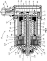
- FIG. 1 shows a longitudinal sectional view of the actuator 10 according to the invention for an internal combustion engine.
- the actuator 10 comprises a multi-part housing 14, within which a designed as electronically commutated DC motor electric motor 18 is arranged.
- the electric motor 18 comprises a stator 22, which is connected in a rotationally fixed manner to the housing 14 and drives a rotor 26 equipped with permanent magnets.
- an electronic unit 30 is arranged, via which the stator 22 is commutated.
- the electronic unit 30 comprises a circuit board 34, on which commutation sensors 38 are arranged, which detect the magnetic field of the rotor 26 and thus the angular position thereof by means of magnetically conductive elements 42 which are arranged between commutation sensor 38 and rotor 26.
- the circuit board 34 is contacted electrically via contacts 46 of a socket 50.
- a stator connecting unit 54 is electrically connected to the circuit board 34 via connecting elements 58.
- the rotor 26 is fixedly connected to a drive shaft 62 designed as a hollow shaft, so that the drive shaft 62 rotates with the rotor 26.
- a two-stage planetary gear 66 is arranged as a transmission, which has a connected to the drive shaft 62 sun gear 70.
- the planetary gear 66 additionally includes planetary gears 74 of a first gear stage 78 and planet gears 79 of a second gear stage 82, which are in engagement with the sun gear 70, so that they are driven by the sun gear 70.
- a toothing 86 of the sun gear 70 is identical for both gear stages 78, 82.
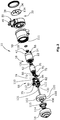
- the first gear stage 78 comprises two planet wheels 74, during which the second gear stage 82 comprises three planet wheels 79 (see FIG. 2 ).
- the planetary gears 74 of the first gear stage 78 and the planet gears 79 of the second gear stage 82 are supported on axles 90 which extend axially from an annular planet carrier 94 disposed between the gear stages 78, 82.
- the planet gears 74 of the first gear stage 78 on the planet carrier 94 relative to the Planetary gears 79 of the second gear stage 82 rotatably supported while their axes 90 are fixedly arranged to each other.
- the planet gears 74 of the first gear stage 78 are in engagement with a stationary ring gear 98, which is fixed in the housing 14.
- the planetary gears 79 of the second gear stage 82 are meshed with a driven gear formed as the output shaft gear 102, which is fixed to an output shaft 106.
- a number of teeth 110 of the planetary gears 74 and ring gear teeth 111 of the first gear stage 78 differs from a number of teeth 112 of the planetary gears 79 and output shaft gear teeth 113 of the second gear stage 82, so that a reduction of the rotation of the drive shaft 62 for rotation of the output shaft 106 is achieved.
- An end of the output shaft 106 axially opposite the electronics unit 30 projects out of the housing 14 and is sealed to the outside via a seal 114.
- a flap body can be arranged on this end.
- the output shaft 106 is mounted in the housing 14 via a first output shaft bearing 115 and a second output shaft bearing 118.
- the first output shaft bearing 115 is arranged on a radial outer side 119 of the output shaft 22 carrying the connecting portion 120
- the second output shaft bearing 118 is disposed on a radial output shaft outer side 121 at an axial end of the part of the output shaft 106 which extends in the direction of the electronic unit 30 through formed as a hollow shaft drive shaft 62 extends.
- the drive shaft 62 via a first drive shaft bearing 122 which at least partially within an axial extension portion of the first output shaft bearing 115, radially inwardly of the first output shaft bearing 115 between a drive shaft outer circumference U A and the connecting portion 120 of the output shaft hollow wheel 102, and a second drive shaft bearing 126, which is arranged axially opposite to the second output shaft bearing 118 between a drive shaft inner circumference U I and the output shaft 106, stored.
- a sensor magnet 130 is arranged, which cooperates with a arranged on the board 34 position sensor 134, so that an angular position of the output shaft 106 is detectable.
- the described actuator according to the invention thus has a high coaxiality of the drive shaft to the output shaft, so that the wear is minimized.
- this coaxiality is achieved by a low production cost, so that the actuator is simpler and thus more economical to produce.
- the scope of protection is not limited to the described embodiment of an actuator, but various modifications and design changes are conceivable.
- the planetary gear is not limited to the number of planetary gears shown, so that even a different number of planetary gears is used.
- the number of teeth of the sun gear between the first gear and second gear can change.
Landscapes
- Engineering & Computer Science (AREA)
- Chemical & Material Sciences (AREA)
- Combustion & Propulsion (AREA)
- Mechanical Engineering (AREA)
- General Engineering & Computer Science (AREA)
- Power Engineering (AREA)
- Retarders (AREA)
- Connection Of Motors, Electrical Generators, Mechanical Devices, And The Like (AREA)
Claims (12)
- Actionneur (10) pour actionner des volets pour un moteur à combustion interne, avec:- un moteur électrique (18) entrainant un arbre d'entraînement (62),- une unité électronique (30), et- un engrenage (66) avec une roue dentée menée (102) disposée coaxialement par rapport à l'arbre d'entrainement (62), l'engrenage (66) reliant l'arbre d'entrainement (62) avec un arbre de sortie (106) dudit actionneur (10),dans lequel l'arbre d'entrainement (62) est conçu comme arbre creux, dans lequel l'arbre de sortie (106) est disposé,
caractérisé en ce que
des paliers (115, 118) de l'arbre de sortie sont disposés entre un carter (14) et l'arbre de sortie (106), de sorte que l'arbre de sortie (106) soit entièrement supporté par le carter (14) dudit actionneur (10) et des paliers (122, 126) de l'arbre d'entrainement soient disposés entre l'arbre d'entrainement (62) et l'arbre de sortie (106), ce par quoi l'arbre d'entrainement (62) est supporté exclusivement sur l'arbre de sortie (106). - Actionneur (10) pour actionner des volets pour un moteur à combustion interne selon la revendication 1, caractérisé en ce que l'engrenage est un engrenage planétaire (66).
- Actionneur (10) pour actionner des volets pour un moteur à combustion interne selon la revendication 1 ou 2, caractérisé en ce que l'arbre d'entrainement (62) est supporté sur l'arbre de sortie (106) par un premier palier (122) de l'arbre d'entrainement en contact avec la circonférence extérieure (UA) de l'arbre d'entrainement, et un deuxième palier (126) de l'arbre d'entrainement en contact avec la circonférence intérieure (UI) de l'arbre de sortie (106).
- Actionneur (10) pour actionner des volets pour un moteur à combustion interne selon l'une quelconque des revendications précédentes, caractérisé en ce qu'un premier palier (115) de l'arbre de sortie est disposé sur un côté extérieur radial (119) d'une section de liaison (120) portant la roue dentée menée (102), et qu'un deuxième palier (118) de l'arbre de sortie est disposé sur un côté extérieure radial (121) de l'arbre de sortie.
- Actionneur (10) pour actionner des volets pour un moteur à combustion interne selon la revendication 4, caractérisé en ce que le premier palier (122) de l'arbre d'entrainement est disposé au moins en partie au sein d'une section de l'étendue du premier palier (115) de l'arbre de sortie.
- Actionneur (10) pour actionner des volets pour un moteur à combustion interne selon la revendication 4 ou 5, caractérisé en ce que le deuxième palier (118) de l'arbre de sortie est disposé axialement à côté du deuxième palier (126) de l'arbre d'entrainement.
- Actionneur (10) pour actionner des volets pour un moteur à combustion interne selon l'une quelconque des revendications précédentes, caractérisé en ce que l'unité électronique (30) est disposée à une extrémité de l'arbre de sortie (106) axialement opposée à la roue dentée menée (102) et comprend un capteur de position (134), un aimant de capteur (130) étant disposé à une extrémité de l'arbre de sortie (106) tournée vers l'unité électronique (30), ledit aimant étant disposé de manière opposée au capteur de position (134).
- Actionneur (10) pour actionner des volets pour un moteur à combustion interne selon l'une quelconque des revendications précédentes, caractérisé en ce que l'unité électronique (30) comprend au moins un capteur de commutation (38) détectant le champ magnétique d'un rotor (26) par un élément (42) magnétiquement conducteur qui est disposé entre le capteur de commutation (38) et un rotor (26) du moteur électrique (18).
- Actionneur (10) pour actionner des volets pour un moteur à combustion interne selon l'une quelconque des revendications précédentes, caractérisé en ce que l'engrenage planétaire (66) comprend deux étages d'engrenage (78, 82) en prise avec l'arbre d'entrainement (62) conçu comme roue solaire (70), des roues planétaires (74, 79) des deux étages d'engrenage (78, 82) étant supportés ensemble sur un support de roue planétaires (94), et les roues planétaires (74) du premier étage d'engrenage (78) étant en prise avec une couronne (98) formée de manière stationnaire sur un carter (14) de l'actionneur (10), et les roues planétaires (79) de la deuxième étage d'engrenage (82) étant en prise avec la roue dentée menée (102) conçue comme couronne (102) de l'arbre de sortie et disposée sur l'arbre de sortie (106).
- Actionneur (10) pour actionner des volets pour un moteur à combustion interne selon la revendication 9, caractérisé en ce que la denture (86) de la roue solaire (70) est identique pour les deux étages d'engrenage (78, 82), le nombre de dents des roues planétaires (74) et de la couronne (98) du premier étage d'engrenage (78) étant différent du nombre de dents des roues planétaires (79) et de la couronne (102) de l'arbre de sortie du deuxième étage d'engrenage (82).
- Actionneur (10) pour actionner des volets pour un moteur à combustion interne selon la revendication 9 ou 10, caractérisé en ce que le support des roues planétaires (94) est disposé entre les étages d'engrenage (78, 82).
- Actionneur (10) pour actionner des volets pour un moteur à combustion interne selon l'une quelconque des revendications 9 à 11, caractérisé en ce que e support des roues planétaires (94) est conçu comme anneau avec des axes (90) aux côtés tournés vers les étages d'engrenage (78, 82), sur lesquels axes les roues planétaires (74, 79) sont supportées.
Applications Claiming Priority (1)
| Application Number | Priority Date | Filing Date | Title |
|---|---|---|---|
| DE102016119092.6A DE102016119092B4 (de) | 2016-10-07 | 2016-10-07 | Aktuator für eine Verbrennungskraftmaschine |
Publications (2)
| Publication Number | Publication Date |
|---|---|
| EP3306057A1 EP3306057A1 (fr) | 2018-04-11 |
| EP3306057B1 true EP3306057B1 (fr) | 2019-08-21 |
Family
ID=60001691
Family Applications (1)
| Application Number | Title | Priority Date | Filing Date |
|---|---|---|---|
| EP17193454.0A Not-in-force EP3306057B1 (fr) | 2016-10-07 | 2017-09-27 | Actionneur pour actionner des volets pour un moteur à combustion interne |
Country Status (2)
| Country | Link |
|---|---|
| EP (1) | EP3306057B1 (fr) |
| DE (1) | DE102016119092B4 (fr) |
Families Citing this family (4)
| Publication number | Priority date | Publication date | Assignee | Title |
|---|---|---|---|---|
| WO2020207574A1 (fr) * | 2019-04-10 | 2020-10-15 | Pierburg Gmbh | Soupape à tiroir rotatif pour véhicule automobile |
| EP3953619B1 (fr) * | 2019-04-10 | 2024-06-05 | Pierburg GmbH | Soupape à tiroir rotatif pour un véhicule automobile |
| DE102024122704A1 (de) * | 2024-08-08 | 2026-02-12 | Dr. Fritz Faulhaber GmbH & Co.KG | Antriebseinheit |
| DE102024209715A1 (de) * | 2024-10-04 | 2026-04-09 | Robert Bosch Gesellschaft mit beschränkter Haftung | Elektromotor-Getriebe-Baueinheit |
Family Cites Families (12)
| Publication number | Priority date | Publication date | Assignee | Title |
|---|---|---|---|---|
| FR2148984A5 (fr) * | 1971-08-05 | 1973-03-23 | Potain Sa | |
| DE29906804U1 (de) | 1999-04-19 | 1999-07-08 | Stegmann Max Antriebstech | Positionier- und Stellantrieb |
| US7098563B2 (en) * | 2003-11-10 | 2006-08-29 | Tai-Her Yang | Drive system having a hollow motor main shaft and a coaxial, manually driven auxiliary shaft |
| DE102005033494A1 (de) * | 2005-07-19 | 2007-01-25 | Daimlerchrysler Ag | Überlagerungsvorrichtung für ein Lenksystem |
| AU2008277325A1 (en) * | 2007-07-18 | 2009-01-22 | Clean Mobile Ag | External-rotor electric motor with or without a planetary gear mechanism, motor vehicle with an external-rotor electric motor and a method for operating such a vehicle |
| US8567540B2 (en) * | 2008-01-25 | 2013-10-29 | Ford Global Technologies, Llc | Drive unit for an electric hybrid vehicle |
| DE102010037017A1 (de) * | 2009-08-17 | 2011-03-10 | Clean Mobile Ag | Außenläufer-Elektromotor, Kraftfahrzeug mit Außenläufer-Elektromotor und Verfahren zum Betreiben eines solchen Fahrzeugs |
| US20120299416A1 (en) * | 2011-05-23 | 2012-11-29 | Chen Koufeng | Gear motor and gear generator |
| CA2907143A1 (fr) * | 2013-03-15 | 2014-09-18 | Springs Window Fashions, Llc | Levage motorise d'habillage de fenetre et systeme de commande et d'actionnement |
| CH707911A1 (de) * | 2013-04-12 | 2014-10-15 | Textilma Ag | Anlage zur Erzeugung von elektrischer Energie. |
| DE102013223409A1 (de) * | 2013-11-15 | 2015-05-21 | Mtu Friedrichshafen Gmbh | Elektro-mechanischer Hybridantrieb und Fahrzeug |
| CN104037979A (zh) * | 2014-06-19 | 2014-09-10 | 浙江西传电气科技有限公司 | 一种差齿减速螺杆泵地面驱动电机 |
-
2016
- 2016-10-07 DE DE102016119092.6A patent/DE102016119092B4/de not_active Expired - Fee Related
-
2017
- 2017-09-27 EP EP17193454.0A patent/EP3306057B1/fr not_active Not-in-force
Non-Patent Citations (1)
| Title |
|---|
| None * |
Also Published As
| Publication number | Publication date |
|---|---|
| EP3306057A1 (fr) | 2018-04-11 |
| DE102016119092B4 (de) | 2018-05-09 |
| DE102016119092A1 (de) | 2018-04-12 |
Similar Documents
| Publication | Publication Date | Title |
|---|---|---|
| DE10160685C2 (de) | Planetengetriebe, Getriebemotor und Baureihe von Getriebemotoren | |
| EP3306057B1 (fr) | Actionneur pour actionner des volets pour un moteur à combustion interne | |
| DE102017211881A1 (de) | Antriebseinrichtung zum Antreiben einer elektrischen Achse | |
| DE102008005322B4 (de) | Getriebemotorreduktionsgetriebe und Getriebemotor | |
| DE10003452A1 (de) | Elektromotor mit Umlaufgetriebe | |
| WO2021078892A1 (fr) | Transmission, train d'entraînement et véhicule comprenant une transmission | |
| DE102005018956A1 (de) | Vorrichtung zur Nockenwellenverstellung einer Brennkraftmaschine | |
| WO2018002285A1 (fr) | Système modulaire pour rouleaux de transport à moteur | |
| DE102016220630A1 (de) | Antriebseinrichtung zum Antreiben einer elektrischen Achse | |
| WO2019214845A1 (fr) | Moteur électrique doté d'un arbre de rotor et d'un premier et d'un second palier | |
| DE102008005421B4 (de) | Überlagerungseinrichtung für Fahrzeuglenkung | |
| DE102015223914B4 (de) | Umlaufrädergetriebe mit Untersetzungsstufe für eine Kraftfahrzeugantriebseinheit | |
| DE102004052562B3 (de) | Kraftfahrzeuglenkung mit Überlagerungsgetriebe | |
| DE102015201158B4 (de) | Aktuatoreinheit | |
| DE102016119091B4 (de) | Aktuator für eine Verbrennungskraftmaschine | |
| WO2014044277A1 (fr) | Système de transmission | |
| DE102016224898A1 (de) | Pumpeneinrichtung für ein Automatikgetriebe | |
| DE102007057391A1 (de) | Zahnstangen-Hilfskraftlenkung | |
| EP2295274A1 (fr) | Unité d'entraînement pour un véhicule automobile | |
| DE102005023032A1 (de) | Elektrische Antriebsvorrichtung | |
| AT510509A1 (de) | Exzenter-kurvenscheibengetriebe | |
| WO2020109144A1 (fr) | Dispositif d'entraînement pour un véhicule automobile comprenant une unité d'entraînement | |
| DE202006014817U1 (de) | Motorischer Stellantrieb für einen Fahrzeugsitz | |
| DE102011076944A1 (de) | Wolfromexzentergetriebe und Vorrichtung mit einem Wolfromexzentergetriebe | |
| DE102009045502B4 (de) | Pressengetriebeanordnung und damit ausgerüstete Exzenterpresse |
Legal Events
| Date | Code | Title | Description |
|---|---|---|---|
| PUAI | Public reference made under article 153(3) epc to a published international application that has entered the european phase |
Free format text: ORIGINAL CODE: 0009012 |
|
| STAA | Information on the status of an ep patent application or granted ep patent |
Free format text: STATUS: THE APPLICATION HAS BEEN PUBLISHED |
|
| AK | Designated contracting states |
Kind code of ref document: A1 Designated state(s): AL AT BE BG CH CY CZ DE DK EE ES FI FR GB GR HR HU IE IS IT LI LT LU LV MC MK MT NL NO PL PT RO RS SE SI SK SM TR |
|
| AX | Request for extension of the european patent |
Extension state: BA ME |
|
| STAA | Information on the status of an ep patent application or granted ep patent |
Free format text: STATUS: REQUEST FOR EXAMINATION WAS MADE |
|
| 17P | Request for examination filed |
Effective date: 20181008 |
|
| RBV | Designated contracting states (corrected) |
Designated state(s): AL AT BE BG CH CY CZ DE DK EE ES FI FR GB GR HR HU IE IS IT LI LT LU LV MC MK MT NL NO PL PT RO RS SE SI SK SM TR |
|
| GRAP | Despatch of communication of intention to grant a patent |
Free format text: ORIGINAL CODE: EPIDOSNIGR1 |
|
| STAA | Information on the status of an ep patent application or granted ep patent |
Free format text: STATUS: GRANT OF PATENT IS INTENDED |
|
| INTG | Intention to grant announced |
Effective date: 20190403 |
|
| GRAS | Grant fee paid |
Free format text: ORIGINAL CODE: EPIDOSNIGR3 |
|
| GRAA | (expected) grant |
Free format text: ORIGINAL CODE: 0009210 |
|
| STAA | Information on the status of an ep patent application or granted ep patent |
Free format text: STATUS: THE PATENT HAS BEEN GRANTED |
|
| AK | Designated contracting states |
Kind code of ref document: B1 Designated state(s): AL AT BE BG CH CY CZ DE DK EE ES FI FR GB GR HR HU IE IS IT LI LT LU LV MC MK MT NL NO PL PT RO RS SE SI SK SM TR |
|
| REG | Reference to a national code |
Ref country code: GB Ref legal event code: FG4D Free format text: NOT ENGLISH |
|
| REG | Reference to a national code |
Ref country code: CH Ref legal event code: EP |
|
| REG | Reference to a national code |
Ref country code: DE Ref legal event code: R096 Ref document number: 502017002079 Country of ref document: DE |
|
| REG | Reference to a national code |
Ref country code: AT Ref legal event code: REF Ref document number: 1170023 Country of ref document: AT Kind code of ref document: T Effective date: 20190915 |
|
| REG | Reference to a national code |
Ref country code: IE Ref legal event code: FG4D Free format text: LANGUAGE OF EP DOCUMENT: GERMAN |
|
| REG | Reference to a national code |
Ref country code: LT Ref legal event code: MG4D |
|
| REG | Reference to a national code |
Ref country code: NL Ref legal event code: MP Effective date: 20190821 |
|
| PG25 | Lapsed in a contracting state [announced via postgrant information from national office to epo] |
Ref country code: NO Free format text: LAPSE BECAUSE OF FAILURE TO SUBMIT A TRANSLATION OF THE DESCRIPTION OR TO PAY THE FEE WITHIN THE PRESCRIBED TIME-LIMIT Effective date: 20191121 Ref country code: BG Free format text: LAPSE BECAUSE OF FAILURE TO SUBMIT A TRANSLATION OF THE DESCRIPTION OR TO PAY THE FEE WITHIN THE PRESCRIBED TIME-LIMIT Effective date: 20191121 Ref country code: SE Free format text: LAPSE BECAUSE OF FAILURE TO SUBMIT A TRANSLATION OF THE DESCRIPTION OR TO PAY THE FEE WITHIN THE PRESCRIBED TIME-LIMIT Effective date: 20190821 Ref country code: PT Free format text: LAPSE BECAUSE OF FAILURE TO SUBMIT A TRANSLATION OF THE DESCRIPTION OR TO PAY THE FEE WITHIN THE PRESCRIBED TIME-LIMIT Effective date: 20191223 Ref country code: HR Free format text: LAPSE BECAUSE OF FAILURE TO SUBMIT A TRANSLATION OF THE DESCRIPTION OR TO PAY THE FEE WITHIN THE PRESCRIBED TIME-LIMIT Effective date: 20190821 Ref country code: FI Free format text: LAPSE BECAUSE OF FAILURE TO SUBMIT A TRANSLATION OF THE DESCRIPTION OR TO PAY THE FEE WITHIN THE PRESCRIBED TIME-LIMIT Effective date: 20190821 Ref country code: LT Free format text: LAPSE BECAUSE OF FAILURE TO SUBMIT A TRANSLATION OF THE DESCRIPTION OR TO PAY THE FEE WITHIN THE PRESCRIBED TIME-LIMIT Effective date: 20190821 Ref country code: NL Free format text: LAPSE BECAUSE OF FAILURE TO SUBMIT A TRANSLATION OF THE DESCRIPTION OR TO PAY THE FEE WITHIN THE PRESCRIBED TIME-LIMIT Effective date: 20190821 |
|
| REG | Reference to a national code |
Ref country code: DE Ref legal event code: R082 Ref document number: 502017002079 Country of ref document: DE Representative=s name: TERPATENT PARTGMBB, DE Ref country code: DE Ref legal event code: R082 Ref document number: 502017002079 Country of ref document: DE Representative=s name: TERPATENT PATENTANWAELTE TER SMITTEN EBERLEIN-, DE |
|
| PG25 | Lapsed in a contracting state [announced via postgrant information from national office to epo] |
Ref country code: ES Free format text: LAPSE BECAUSE OF FAILURE TO SUBMIT A TRANSLATION OF THE DESCRIPTION OR TO PAY THE FEE WITHIN THE PRESCRIBED TIME-LIMIT Effective date: 20190821 Ref country code: RS Free format text: LAPSE BECAUSE OF FAILURE TO SUBMIT A TRANSLATION OF THE DESCRIPTION OR TO PAY THE FEE WITHIN THE PRESCRIBED TIME-LIMIT Effective date: 20190821 Ref country code: GR Free format text: LAPSE BECAUSE OF FAILURE TO SUBMIT A TRANSLATION OF THE DESCRIPTION OR TO PAY THE FEE WITHIN THE PRESCRIBED TIME-LIMIT Effective date: 20191122 Ref country code: AL Free format text: LAPSE BECAUSE OF FAILURE TO SUBMIT A TRANSLATION OF THE DESCRIPTION OR TO PAY THE FEE WITHIN THE PRESCRIBED TIME-LIMIT Effective date: 20190821 Ref country code: LV Free format text: LAPSE BECAUSE OF FAILURE TO SUBMIT A TRANSLATION OF THE DESCRIPTION OR TO PAY THE FEE WITHIN THE PRESCRIBED TIME-LIMIT Effective date: 20190821 Ref country code: IS Free format text: LAPSE BECAUSE OF FAILURE TO SUBMIT A TRANSLATION OF THE DESCRIPTION OR TO PAY THE FEE WITHIN THE PRESCRIBED TIME-LIMIT Effective date: 20191221 |
|
| PG25 | Lapsed in a contracting state [announced via postgrant information from national office to epo] |
Ref country code: TR Free format text: LAPSE BECAUSE OF FAILURE TO SUBMIT A TRANSLATION OF THE DESCRIPTION OR TO PAY THE FEE WITHIN THE PRESCRIBED TIME-LIMIT Effective date: 20190821 |
|
| PG25 | Lapsed in a contracting state [announced via postgrant information from national office to epo] |
Ref country code: PL Free format text: LAPSE BECAUSE OF FAILURE TO SUBMIT A TRANSLATION OF THE DESCRIPTION OR TO PAY THE FEE WITHIN THE PRESCRIBED TIME-LIMIT Effective date: 20190821 Ref country code: RO Free format text: LAPSE BECAUSE OF FAILURE TO SUBMIT A TRANSLATION OF THE DESCRIPTION OR TO PAY THE FEE WITHIN THE PRESCRIBED TIME-LIMIT Effective date: 20190821 Ref country code: DK Free format text: LAPSE BECAUSE OF FAILURE TO SUBMIT A TRANSLATION OF THE DESCRIPTION OR TO PAY THE FEE WITHIN THE PRESCRIBED TIME-LIMIT Effective date: 20190821 Ref country code: EE Free format text: LAPSE BECAUSE OF FAILURE TO SUBMIT A TRANSLATION OF THE DESCRIPTION OR TO PAY THE FEE WITHIN THE PRESCRIBED TIME-LIMIT Effective date: 20190821 Ref country code: IT Free format text: LAPSE BECAUSE OF FAILURE TO SUBMIT A TRANSLATION OF THE DESCRIPTION OR TO PAY THE FEE WITHIN THE PRESCRIBED TIME-LIMIT Effective date: 20190821 |
|
| PG25 | Lapsed in a contracting state [announced via postgrant information from national office to epo] |
Ref country code: SM Free format text: LAPSE BECAUSE OF FAILURE TO SUBMIT A TRANSLATION OF THE DESCRIPTION OR TO PAY THE FEE WITHIN THE PRESCRIBED TIME-LIMIT Effective date: 20190821 Ref country code: CZ Free format text: LAPSE BECAUSE OF FAILURE TO SUBMIT A TRANSLATION OF THE DESCRIPTION OR TO PAY THE FEE WITHIN THE PRESCRIBED TIME-LIMIT Effective date: 20190821 Ref country code: SK Free format text: LAPSE BECAUSE OF FAILURE TO SUBMIT A TRANSLATION OF THE DESCRIPTION OR TO PAY THE FEE WITHIN THE PRESCRIBED TIME-LIMIT Effective date: 20190821 Ref country code: IS Free format text: LAPSE BECAUSE OF FAILURE TO SUBMIT A TRANSLATION OF THE DESCRIPTION OR TO PAY THE FEE WITHIN THE PRESCRIBED TIME-LIMIT Effective date: 20200224 Ref country code: MC Free format text: LAPSE BECAUSE OF FAILURE TO SUBMIT A TRANSLATION OF THE DESCRIPTION OR TO PAY THE FEE WITHIN THE PRESCRIBED TIME-LIMIT Effective date: 20190821 |
|
| REG | Reference to a national code |
Ref country code: DE Ref legal event code: R097 Ref document number: 502017002079 Country of ref document: DE |
|
| PLBE | No opposition filed within time limit |
Free format text: ORIGINAL CODE: 0009261 |
|
| STAA | Information on the status of an ep patent application or granted ep patent |
Free format text: STATUS: NO OPPOSITION FILED WITHIN TIME LIMIT |
|
| PG2D | Information on lapse in contracting state deleted |
Ref country code: IS |
|
| PG25 | Lapsed in a contracting state [announced via postgrant information from national office to epo] |
Ref country code: LU Free format text: LAPSE BECAUSE OF NON-PAYMENT OF DUE FEES Effective date: 20190927 Ref country code: IE Free format text: LAPSE BECAUSE OF NON-PAYMENT OF DUE FEES Effective date: 20190927 |
|
| 26N | No opposition filed |
Effective date: 20200603 |
|
| REG | Reference to a national code |
Ref country code: BE Ref legal event code: MM Effective date: 20190930 |
|
| PG25 | Lapsed in a contracting state [announced via postgrant information from national office to epo] |
Ref country code: BE Free format text: LAPSE BECAUSE OF NON-PAYMENT OF DUE FEES Effective date: 20190930 Ref country code: SI Free format text: LAPSE BECAUSE OF FAILURE TO SUBMIT A TRANSLATION OF THE DESCRIPTION OR TO PAY THE FEE WITHIN THE PRESCRIBED TIME-LIMIT Effective date: 20190821 |
|
| PG25 | Lapsed in a contracting state [announced via postgrant information from national office to epo] |
Ref country code: FR Free format text: LAPSE BECAUSE OF NON-PAYMENT OF DUE FEES Effective date: 20191021 |
|
| REG | Reference to a national code |
Ref country code: CH Ref legal event code: PL |
|
| PG25 | Lapsed in a contracting state [announced via postgrant information from national office to epo] |
Ref country code: CY Free format text: LAPSE BECAUSE OF FAILURE TO SUBMIT A TRANSLATION OF THE DESCRIPTION OR TO PAY THE FEE WITHIN THE PRESCRIBED TIME-LIMIT Effective date: 20190821 |
|
| PG25 | Lapsed in a contracting state [announced via postgrant information from national office to epo] |
Ref country code: HU Free format text: LAPSE BECAUSE OF FAILURE TO SUBMIT A TRANSLATION OF THE DESCRIPTION OR TO PAY THE FEE WITHIN THE PRESCRIBED TIME-LIMIT; INVALID AB INITIO Effective date: 20170927 Ref country code: MT Free format text: LAPSE BECAUSE OF FAILURE TO SUBMIT A TRANSLATION OF THE DESCRIPTION OR TO PAY THE FEE WITHIN THE PRESCRIBED TIME-LIMIT Effective date: 20190821 |
|
| PG25 | Lapsed in a contracting state [announced via postgrant information from national office to epo] |
Ref country code: LI Free format text: LAPSE BECAUSE OF NON-PAYMENT OF DUE FEES Effective date: 20200930 Ref country code: CH Free format text: LAPSE BECAUSE OF NON-PAYMENT OF DUE FEES Effective date: 20200930 |
|
| GBPC | Gb: european patent ceased through non-payment of renewal fee |
Effective date: 20210927 |
|
| PG25 | Lapsed in a contracting state [announced via postgrant information from national office to epo] |
Ref country code: MK Free format text: LAPSE BECAUSE OF FAILURE TO SUBMIT A TRANSLATION OF THE DESCRIPTION OR TO PAY THE FEE WITHIN THE PRESCRIBED TIME-LIMIT Effective date: 20190821 |
|
| PG25 | Lapsed in a contracting state [announced via postgrant information from national office to epo] |
Ref country code: GB Free format text: LAPSE BECAUSE OF NON-PAYMENT OF DUE FEES Effective date: 20210927 |
|
| REG | Reference to a national code |
Ref country code: AT Ref legal event code: MM01 Ref document number: 1170023 Country of ref document: AT Kind code of ref document: T Effective date: 20220927 |
|
| PGFP | Annual fee paid to national office [announced via postgrant information from national office to epo] |
Ref country code: DE Payment date: 20230919 Year of fee payment: 7 |
|
| PG25 | Lapsed in a contracting state [announced via postgrant information from national office to epo] |
Ref country code: AT Free format text: LAPSE BECAUSE OF NON-PAYMENT OF DUE FEES Effective date: 20220927 |
|
| REG | Reference to a national code |
Ref country code: DE Ref legal event code: R119 Ref document number: 502017002079 Country of ref document: DE |
|
| PG25 | Lapsed in a contracting state [announced via postgrant information from national office to epo] |
Ref country code: DE Free format text: LAPSE BECAUSE OF NON-PAYMENT OF DUE FEES Effective date: 20250401 |