EP3306090A1 - Piezoelektrische keramische luftpumpe und konstruktionsverfahren dafür - Google Patents
Piezoelektrische keramische luftpumpe und konstruktionsverfahren dafür Download PDFInfo
- Publication number
- EP3306090A1 EP3306090A1 EP16887181.2A EP16887181A EP3306090A1 EP 3306090 A1 EP3306090 A1 EP 3306090A1 EP 16887181 A EP16887181 A EP 16887181A EP 3306090 A1 EP3306090 A1 EP 3306090A1
- Authority
- EP
- European Patent Office
- Prior art keywords
- piezoelectric ceramic
- air inlet
- air
- pump
- outlet
- Prior art date
- Legal status (The legal status is an assumption and is not a legal conclusion. Google has not performed a legal analysis and makes no representation as to the accuracy of the status listed.)
- Granted
Links
Images




Classifications
-
- F—MECHANICAL ENGINEERING; LIGHTING; HEATING; WEAPONS; BLASTING
- F04—POSITIVE - DISPLACEMENT MACHINES FOR LIQUIDS; PUMPS FOR LIQUIDS OR ELASTIC FLUIDS
- F04B—POSITIVE-DISPLACEMENT MACHINES FOR LIQUIDS; PUMPS
- F04B45/00—Pumps or pumping installations having flexible working members and specially adapted for elastic fluids
- F04B45/04—Pumps or pumping installations having flexible working members and specially adapted for elastic fluids having plate-like flexible members, e.g. diaphragms
- F04B45/043—Pumps or pumping installations having flexible working members and specially adapted for elastic fluids having plate-like flexible members, e.g. diaphragms two or more plate-like pumping flexible members in parallel
-
- F—MECHANICAL ENGINEERING; LIGHTING; HEATING; WEAPONS; BLASTING
- F04—POSITIVE - DISPLACEMENT MACHINES FOR LIQUIDS; PUMPS FOR LIQUIDS OR ELASTIC FLUIDS
- F04B—POSITIVE-DISPLACEMENT MACHINES FOR LIQUIDS; PUMPS
- F04B45/00—Pumps or pumping installations having flexible working members and specially adapted for elastic fluids
- F04B45/04—Pumps or pumping installations having flexible working members and specially adapted for elastic fluids having plate-like flexible members, e.g. diaphragms
- F04B45/047—Pumps having electric drive
-
- F—MECHANICAL ENGINEERING; LIGHTING; HEATING; WEAPONS; BLASTING
- F04—POSITIVE - DISPLACEMENT MACHINES FOR LIQUIDS; PUMPS FOR LIQUIDS OR ELASTIC FLUIDS
- F04B—POSITIVE-DISPLACEMENT MACHINES FOR LIQUIDS; PUMPS
- F04B2205/00—Fluid parameters
- F04B2205/01—Pressure before the pump inlet
-
- F—MECHANICAL ENGINEERING; LIGHTING; HEATING; WEAPONS; BLASTING
- F04—POSITIVE - DISPLACEMENT MACHINES FOR LIQUIDS; PUMPS FOR LIQUIDS OR ELASTIC FLUIDS
- F04B—POSITIVE-DISPLACEMENT MACHINES FOR LIQUIDS; PUMPS
- F04B2205/00—Fluid parameters
- F04B2205/09—Flow through the pump
-
- F—MECHANICAL ENGINEERING; LIGHTING; HEATING; WEAPONS; BLASTING
- F04—POSITIVE - DISPLACEMENT MACHINES FOR LIQUIDS; PUMPS FOR LIQUIDS OR ELASTIC FLUIDS
- F04B—POSITIVE-DISPLACEMENT MACHINES FOR LIQUIDS; PUMPS
- F04B43/00—Machines, pumps, or pumping installations having flexible working members
- F04B43/02—Machines, pumps, or pumping installations having flexible working members having plate-like flexible members, e.g. diaphragms
- F04B43/025—Machines, pumps, or pumping installations having flexible working members having plate-like flexible members, e.g. diaphragms two or more plate-like pumping members in parallel
-
- F—MECHANICAL ENGINEERING; LIGHTING; HEATING; WEAPONS; BLASTING
- F04—POSITIVE - DISPLACEMENT MACHINES FOR LIQUIDS; PUMPS FOR LIQUIDS OR ELASTIC FLUIDS
- F04B—POSITIVE-DISPLACEMENT MACHINES FOR LIQUIDS; PUMPS
- F04B43/00—Machines, pumps, or pumping installations having flexible working members
- F04B43/02—Machines, pumps, or pumping installations having flexible working members having plate-like flexible members, e.g. diaphragms
- F04B43/04—Pumps having electric drive
- F04B43/043—Micropumps
- F04B43/046—Micropumps with piezoelectric drive
-
- F—MECHANICAL ENGINEERING; LIGHTING; HEATING; WEAPONS; BLASTING
- F04—POSITIVE - DISPLACEMENT MACHINES FOR LIQUIDS; PUMPS FOR LIQUIDS OR ELASTIC FLUIDS
- F04B—POSITIVE-DISPLACEMENT MACHINES FOR LIQUIDS; PUMPS
- F04B53/00—Component parts, details or accessories not provided for in, or of interest apart from, groups F04B1/00 - F04B23/00 or F04B39/00 - F04B47/00
- F04B53/10—Valves; Arrangement of valves
- F04B53/1037—Flap valves
- F04B53/1047—Flap valves the valve being formed by one or more flexible elements
-
- F—MECHANICAL ENGINEERING; LIGHTING; HEATING; WEAPONS; BLASTING
- F04—POSITIVE - DISPLACEMENT MACHINES FOR LIQUIDS; PUMPS FOR LIQUIDS OR ELASTIC FLUIDS
- F04B—POSITIVE-DISPLACEMENT MACHINES FOR LIQUIDS; PUMPS
- F04B53/00—Component parts, details or accessories not provided for in, or of interest apart from, groups F04B1/00 - F04B23/00 or F04B39/00 - F04B47/00
- F04B53/22—Arrangements for enabling ready assembly or disassembly
Definitions
- the present invention relates to variable displacement hydraulic pumps, and in particular, relates to an air pump in which an alternating current power drives a piezoelectric ceramic sheet to vibrate.
- the present invention provides a design solution of a highly efficient and small-sized piezoelectric ceramic air pump.
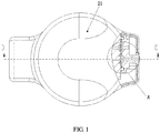
- the piezoelectric ceramic air pump comprises: a pump body , a piezoelectric ceramic crystal diaphragm, and air inlet and output valves; wherein the piezoelectric ceramic crystal diaphragm is co-central-axially mounted on the pump body to construct a working pump chamber for the piezoelectric ceramic air pump; the pump body is approximately tubular, with the diameter being much greater than the axial length, and air inlet and outlet ports configured to communicate the working pump chamber with an external air passage are arranged at a position of a peripheral wall of the pump body; and the air inlet and output valves are mounted at the position of the air inlet and outlet ports.
- piezoelectric ceramic air pump only one piezoelectric ceramic crystal diaphragm is mounted, and the piezoelectric ceramic crystal diaphragm is fitted and fixed onto the pump body via a lower pump cover, and seals and encloses the pump body to construct the working pump chamber.
- two piezoelectric ceramic crystal diaphragms including upper and lower piezoelectric ceramic crystal diaphragms are mounted; wherein the upper and lower piezoelectric ceramic crystal diaphragms are respectively fitted and fixed onto inner sides of upper and lower parts of the pump body via upper and lower pump cover; and the upper and lower piezoelectric ceramic crystal diaphragms are coaxially oppositely arranged on an outer surface of a metal substrate thereof, and seal and enclose the pump body to construct the shared working pump chamber.
- the air inlet and outlet ports are adjacently or non-adjacently arranged on the peripheral wall on one side of the pump body, or the air inlet and outlet ports are oppositely arranged on peripheral walls at two ends of a diameter line of the pump body.
- the piezoelectric ceramic air pump further comprises an air inlet and outlet component configured to respectively laminate the air inlet and outlet valves onto the air inlet and outlet ports, such that the air inlet and outlet holes on the air inlet and outlet component are in communication with the air inlet and outlet valves and the air inlet and outlet ports to form air inlet and outlet passages in communication with the external air passage; and the air inlet and outlet valves are independently molded or manufactured into an integral valve sheet which is provided with a positioning hole configured to perform fitting-based positioning on the peripheral wall of the pump body.
- the piezoelectric ceramic crystal diaphragm seals and encloses the pump body via a first sealing ring arranged on one side of the piezoelectric ceramic crystal diaphragm to construct the working pump chamber; and the lower pump cover is fitted and fixed onto the pump body via a second sealing ring.
- a spacer that is configured to support and isolate the upper and lower piezoelectric ceramic crystal diaphragms and parallel thereto is provided in the pump body, wherein an opening is provided on the spacer in the vicinity of the air inlet and outlet valves, such that the working pump chamber is shared by the upper and lower piezoelectric ceramic crystal diaphragms; and the upper and lower piezoelectric ceramic crystal diaphragms are laminated on the spacer respectively via third and fourth sealing rings, and seal and enclose the pump body via the opening to construct the working pump chamber with a cross section in the shape of a horizontal U.
- an annular boss that supports the upper and lower piezoelectric ceramic crystal diaphragms and inwardly protrudes is coaxially arranged on an inner wall of the pump body, and the upper and lower piezoelectric ceramic crystal diaphragms are laminated on the annular boss via third and fourth sealing rings, and seal and enclose the pump body to construct the working pump chamber in the shape of an oval; and the upper and lower pump cover are respectively laminated and fixedly connected onto the pump body via fifth and sixth sealing rings.
- an end portion of the air outlet port on the pump body is an annular-surfaced arc shape, such that the pump body is in line contact with the end portion of the air outlet port when the air outlet valve is turned off; and an end portion of the air outlet component is also an annular-surfaced arc shape, such that the pump body is in line contact with an end portion of the air inlet hole when the air inlet valve is turned off.
- the piezoelectric ceramic crystal diaphragm further comprises an insulating layer and a silver plating layer arranged on the metal substrate, wherein a piezoelectric ceramic layer is arranged between the insulating layer and the silver plating layer, and electrodes of the piezoelectric ceramic crystal diaphragm are respectively led out from the metal substrate and the silver plating layer.
- a technical solution employed by the present invention to solve the technical problem in the prior art may also be a construction method of a piezoelectric ceramic air pump, based on a main structure comprising a pump body, a piezoelectric ceramic crystal diaphragm, and air inlet and output valves, the piezoelectric ceramic crystal diaphragm being co-central-axially mounted on the pump body to construct a working pump chamber for the piezoelectric ceramic air pump; wherein the method comprises step A: adjacently arranging air inlet and output ports configured to communicate the working pump chamber and an external air passage on a peripheral wall on one side of the pump body, wherein the air inlet and outlet valves are mounted at the position of the air inlet and outlet ports.
- the method further comprises step B: mounting two piezoelectric ceramic crystal diaphragms, including upper and lower piezoelectric ceramic crystal diaphragms; wherein the upper and lower piezoelectric ceramic crystal diaphragms are coaxially oppositely arranged on an outer surface of a metal substrate thereof, and seal and enclose the pump body to construct the shared working pump chamber.
- the method further comprises step C: arranging a spacer that is configured to support and isolate the upper and lower piezoelectric ceramic crystal diaphragms and parallel thereto in the pump body, wherein an opening is provided on the spacer in the vicinity of the air inlet and outlet valves, such that the dead cavity of the shared working pump chamber is reduced and the pumping efficiency is improved.
- the method further comprises step D: simultaneously compressing towards each other or expansion-wise axially moves away from each other by the upper and lower piezoelectric ceramic crystal diaphragms within each power source semi-cycle when an alternating current excitation voltage is applied to the upper and lower piezoelectric ceramic crystal diaphragms.
- the method further comprises step E: respectively laminating the air inlet and outlet valves onto the air inlet and outlet ports, such that the air inlet and outlet holes on the air inlet and outlet component are in communication with the air inlet and outlet valves and the air inlet and outlet ports to form air inlet and outlet passages in communication with the external air passage; and the air inlet and outlet valves are manufactured into an integral valve sheet which is provided with a positioning hole configured to perform fitting-based positioning on the peripheral wall of the pump body.
- the present invention achieves the following beneficial effects:
- the air inlet and outlet ports for communication between the working pump chamber and the external air passage are arranged on the peripheral wall of the pump body, and the inlet and outlet valves are arranged thereon, such that the air inlet and outlet passages for communication between the working pump chamber and the external fluid are simplified, the pipeline in which the fluid flows is shortened, the resistance of the pipeline is reduced, the volume of the dead cavity is decreased, and the efficiency of fluid pumping is improved.
- the number of piezoelectric ceramic crystal diaphragms may be flexibly set to one or two according to the flow rate in practice, and a lot of components are shared in the piezoelectric ceramic air pump, thereby lowering the cost of manufacturing air pumps with different powers.
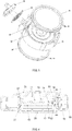
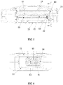
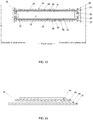
- two piezoelectric ceramic crystal diaphragms 50 are mounted; wherein an upper piezoelectric ceramic crystal diaphragm 51 and a lower piezoelectric ceramic crystal diaphragm 53 are respectively fitted and fixed onto inner sides of upper and lower parts of a pump body 10 via an upper pump cover 21 and a lower pump cover 23; and the upper and lower piezoelectric ceramic crystal diaphragms are coaxially oppositely arranged on an outer surface of a metal substrate 91 thereof, and seal and enclose the pump body 10 to construct a shared working pump chamber 15.
- a spacer 14 that is configured to support and isolate the upper and lower piezoelectric ceramic crystal diaphragms and parallel thereto is provided in the pump body 10, wherein an opening 16 is provided on the spacer 14 in the vicinity of the air inlet and outlet valves, such that the working pump chamber 15 is shared by the upper and lower piezoelectric ceramic crystal diaphragms; and the upper and lower piezoelectric ceramic crystal diaphragms are laminated on the spacer 14 respectively via a third sealing ring 55 and a fourth sealing ring 57, and seal and enclose the pump body 10 via the opening 16 to construct the working pump chamber 15 with a cross section in the shape of a horizontal U.
- the opening 16 is provided on the spacer 14 in the vicinity of the air inlet and outlet valves, such that the dead cavity of the shared working pump chamber 15 is reduced and the pumping efficiency is improved.
- an annular boss 12 that supports the upper and lower piezoelectric ceramic crystal diaphragms and inwardly protrudes is coaxially arranged on an inner wall of the pump body 10, and the upper and lower piezoelectric ceramic crystal diaphragms are laminated on the annular boss 12 via a third sealing ring 55 and a fourth sealing ring 57, and seal and enclose the pump body 10 to construct the working pump chamber 15 in the shape of an oval.
- the upper pump cover 21 and the lower pump cover 23 are respectively laminated and fixedly connected onto the pump body 10 via a fifth sealing ring 25 and a sixth sealing ring 27.
- piezoelectric ceramic air pump as illustrated in FIG. 1 to FIG. 5 , only one piezoelectric ceramic crystal diaphragm 50 is mounted, and the piezoelectric ceramic crystal diaphragm 50 is fitted and fixed onto the pump body 10 via the lower pump cover 23, and seals and encloses the pump body 10 to construct the working pump chamber 15.
- the piezoelectric ceramic crystal diaphragm 50 seals and encloses the pump body 10 via a first sealing ring 59 arranged on one side of the piezoelectric ceramic crystal diaphragm 50 to construct the working pump chamber 15; and the lower pump cover 23 is fitted and fixed onto the pump body 10 via a second sealing ring 29.
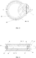
- the air inlet port 17 and the air outlet port 18 are adjacently or non-adjacently arranged on the peripheral wall on one side of the pump body 10; an air inlet and outlet component 70 respectively laminates the air inlet valve 61 and the air outlet valve 63 onto the air inlet and outlet ports, such that an air inlet hole 71 and an air outlet hole 73 on the air inlet and outlet component 70 are in communication with the air inlet and outlet valves and the air inlet and outlet ports to form an air inlet passage 81 and an air outlet passage 83 in communication with an external air passage.
- the air inlet and outlet ports may also be oppositely arranged on peripheral walls at two ends of a diameter line of the pump body 10.
- the air inlet passage 81 has an air inlet valve space 82 on the side on which the air inlet valve 61 is turned on or off; and the air outlet passage 83 has an air outlet valve space 84 on the side on which the air outlet valve 63 is turned on or off.
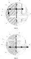
- FIG. 8 is a schematic view of an air inlet state of the piezoelectric ceramic air pump.
- the arrow direction represents an air inlet direction; in case where the air is taken in, i.e., when the piezoelectric ceramic diaphragm 50 vibrates and causes deformation outwardly, the volume of the working pump chamber 15 increases and a negative pressure is formed in the working pump chamber 15, the air inlet valve 61 is pushed open by the negative pressure, and the air outlet valve 63 is suctioned closed by the negative pressure. In this case, an external fluid enters the working pump chamber 15 through the air inlet valve 61 and the air inlet hole 71 sequentially.
- FIG. 9 is a schematic view of an air outlet state of the piezoelectric ceramic air pump.
- the arrow direction represents an air outlet direction; in case where the air is taken in, i.e., when the piezoelectric ceramic diaphragm 50 vibrates and causes deformation in the working pump chamber 15, the volume of the working pump chamber 15 decreases, a positive pressure is formed in the working pump chamber 15, the air inlet valve 61 is suctioned closed by the positive pressure, and the air outlet valve 63 is pushed open by the positive pressure. In this case, an fluid in the working pump chamber 15 flows through the air outlet hole 73 and the air outlet valve 63 sequentially.
- the air inlet valve 61 and the air outlet valve 63 are manufactured into an integral valve sheet 60.
- the air inlet valve 61 and the air outlet valve 63 are independently arranged, or may be shared, that is, the air inlet valve 61 and the air outlet valve 63 are the same component. As illustrated in FIG. 10 and FIG.
- the air inlet valve 61 and the air outlet valve 63 or the integral valve sheet 60 is provided with a positioning hole 66 configured to perform fitting-based positioning on the peripheral wall of the pump body 10, such that the air inlet valve 61 is accurately aligned with the air inlet port 17 on the peripheral wall of the pump body 10, and such that the air outlet valve 63 is accurately aligned with the air outlet port 18 on the peripheral wall of the pump body 10.
- the piezoelectric ceramic crystal diaphragm 50 further comprises an insulating layer 92 and a silver plating layer 94 arranged on the metal substrate 91, wherein a piezoelectric ceramic layer 93 is arranged between the insulating layer and the silver plating layer, and electrodes of the piezoelectric ceramic crystal diaphragm are respectively led out from the metal substrate 91 and the silver plating layer 94.
- the method further comprises: simultaneously compressing towards each other or expansion-wise axially moves away from each other by the upper and lower piezoelectric ceramic crystal diaphragms within each power source semi-cycle when an alternating current excitation voltage is applied to the upper and lower piezoelectric ceramic crystal diaphragms.
- the arrangement of the piezoelectric ceramic crystal diaphragm and the manner of applying the alternating current excitation voltage greatly increase the extrusion efficiency of the fluid in the working pump chamber under extrusion by the diaphragm.
- the piezoelectric ceramic air pump has a small flow rate which is generally between 0.3 L/min and 0.5 L/min.
- the piezoelectric ceramic air pump in the technical solution of the present invention has a reasonable deployment of air passages, and thus the operating efficiency of the air pump is improved. Therefore, the piezoelectric ceramic air pump according to the present invention is a highly efficient miniature air pump.
- a sample designed according to the solution of a preferred embodiment of the present invention is compared with a conventional piezoelectric ceramic air pump in the prior art under the same conditions.
- the comparison test as listed in Table 1, reveals that although the desired sample has two piezoelectric ceramic diaphragms, the actual power consumption is two-fold lower than that of a single piezoelectric ceramic diaphragm, and the output flow rate is two-fold greater than that of the single piezoelectric ceramic crystal diaphragm.
- the technical solution according to the present invention is superior over the prior art, with the flow rate output capability and the energy efficiency being both better over the prior art.
- Table 1 Test sample Voltage/Frequ ency Current (mA) Power (W) Flow rate (L/min) Piezoelectric ceramic air pump in the prior art 120/60 39.5 0.48 0.36 Sample designed according to the solution of a preferred embodiment 120/60 46.15 0.76 0.90
Landscapes
- Engineering & Computer Science (AREA)
- Mechanical Engineering (AREA)
- General Engineering & Computer Science (AREA)
- Reciprocating Pumps (AREA)
Applications Claiming Priority (1)
| Application Number | Priority Date | Filing Date | Title |
|---|---|---|---|
| PCT/CN2016/072799 WO2017128297A1 (zh) | 2016-01-29 | 2016-01-29 | 压电陶瓷气泵及其构筑方法 |
Publications (3)
| Publication Number | Publication Date |
|---|---|
| EP3306090A1 true EP3306090A1 (de) | 2018-04-11 |
| EP3306090A4 EP3306090A4 (de) | 2019-01-23 |
| EP3306090B1 EP3306090B1 (de) | 2020-01-08 |
Family
ID=59397200
Family Applications (1)
| Application Number | Title | Priority Date | Filing Date |
|---|---|---|---|
| EP16887181.2A Active EP3306090B1 (de) | 2016-01-29 | 2016-01-29 | Piezoelektrische keramische luftpumpe und konstruktionsverfahren dafür |
Country Status (3)
| Country | Link |
|---|---|
| US (1) | US20180209412A1 (de) |
| EP (1) | EP3306090B1 (de) |
| WO (1) | WO2017128297A1 (de) |
Cited By (3)
| Publication number | Priority date | Publication date | Assignee | Title |
|---|---|---|---|---|
| EP3501389A1 (de) * | 2017-12-22 | 2019-06-26 | Iradimed Corporation | Fluidpumpen für den einsatz in mrt-umgebung |
| CN110799753A (zh) * | 2018-09-30 | 2020-02-14 | 深圳市大疆软件科技有限公司 | 隔膜泵及农业无人机 |
| US12246165B2 (en) | 2007-07-13 | 2025-03-11 | Iradimed Corporation | System and method for communication with an infusion device |
Families Citing this family (6)
| Publication number | Priority date | Publication date | Assignee | Title |
|---|---|---|---|---|
| US7553295B2 (en) | 2002-06-17 | 2009-06-30 | Iradimed Corporation | Liquid infusion apparatus |
| TWI646262B (zh) * | 2017-10-27 | 2019-01-01 | 研能科技股份有限公司 | 氣體輸送裝置 |
| CN108833645A (zh) * | 2018-09-04 | 2018-11-16 | 金丘科技(深圳)有限公司 | 一种固定装置及手机支架 |
| EP3857077A4 (de) * | 2018-09-25 | 2022-05-25 | Sun Automation, Inc. | Elektrisch betriebene membrantintenpumpvorrichtung und verfahren |
| CN111550390B (zh) * | 2020-05-20 | 2025-04-15 | 成都航空职业技术学院 | 一种压电液压泵 |
| CN112727750B (zh) * | 2021-01-05 | 2022-09-06 | 绍兴泰格机电技术有限公司 | 一种齿轮泵及其制备工艺 |
Family Cites Families (15)
| Publication number | Priority date | Publication date | Assignee | Title |
|---|---|---|---|---|
| US3029743A (en) * | 1960-04-14 | 1962-04-17 | Curtiss Wright Corp | Ceramic diaphragm pump |
| US3657930A (en) * | 1969-06-24 | 1972-04-25 | Bendix Corp | Piezoelectric crystal operated pump to supply fluid pressure to hydrostatically support inner bearings of a gyroscope |
| CN1082625C (zh) * | 1999-07-07 | 2002-04-10 | 张建辉 | 一种带有三通式出入口的压电陶瓷泵 |
| US7287965B2 (en) * | 2004-04-02 | 2007-10-30 | Adaptiv Energy Llc | Piezoelectric devices and methods and circuits for driving same |
| CN1840903A (zh) * | 2005-03-31 | 2006-10-04 | 中国科学院空间科学与应用研究中心 | 一种压电薄膜式流体泵 |
| JP2007165664A (ja) * | 2005-12-15 | 2007-06-28 | Alps Electric Co Ltd | 振動子の配線構造及び圧電ポンプ |
| JP2007198165A (ja) * | 2006-01-24 | 2007-08-09 | Star Micronics Co Ltd | ダイヤフラムポンプ |
| JP4976157B2 (ja) * | 2007-02-16 | 2012-07-18 | アルプス電気株式会社 | 圧電ポンプ及び圧電振動子 |
| US8385578B2 (en) * | 2007-11-12 | 2013-02-26 | Nec Corporation | Piezoelectric acoustic device and electronic apparatus |
| CN101550925B (zh) * | 2008-03-31 | 2014-08-27 | 研能科技股份有限公司 | 具有多个双腔体致动结构的流体输送装置 |
| US9427505B2 (en) * | 2012-05-15 | 2016-08-30 | Smith & Nephew Plc | Negative pressure wound therapy apparatus |
| WO2014105898A1 (en) * | 2012-12-26 | 2014-07-03 | Applied Cavitation, Inc. | Piezoelectric devices |
| DE112014002557T5 (de) * | 2013-05-24 | 2016-03-03 | Murata Manufacturing Co., Ltd. | Vorrichtung zur Ventil- und Flüssigkeitsregelung |
| CN205478232U (zh) * | 2016-01-29 | 2016-08-17 | 深圳市兴日生实业有限公司 | 压电陶瓷气泵 |
| US10655620B2 (en) * | 2016-11-10 | 2020-05-19 | Microjet Technology Co., Ltd. | Miniature fluid control device |
-
2016
- 2016-01-29 US US15/742,495 patent/US20180209412A1/en not_active Abandoned
- 2016-01-29 EP EP16887181.2A patent/EP3306090B1/de active Active
- 2016-01-29 WO PCT/CN2016/072799 patent/WO2017128297A1/zh not_active Ceased
Cited By (4)
| Publication number | Priority date | Publication date | Assignee | Title |
|---|---|---|---|---|
| US12246165B2 (en) | 2007-07-13 | 2025-03-11 | Iradimed Corporation | System and method for communication with an infusion device |
| US12251534B2 (en) | 2007-07-13 | 2025-03-18 | Iradimed Corporation | System for communication with an infusion device |
| EP3501389A1 (de) * | 2017-12-22 | 2019-06-26 | Iradimed Corporation | Fluidpumpen für den einsatz in mrt-umgebung |
| CN110799753A (zh) * | 2018-09-30 | 2020-02-14 | 深圳市大疆软件科技有限公司 | 隔膜泵及农业无人机 |
Also Published As
| Publication number | Publication date |
|---|---|
| WO2017128297A1 (zh) | 2017-08-03 |
| US20180209412A1 (en) | 2018-07-26 |
| EP3306090B1 (de) | 2020-01-08 |
| EP3306090A4 (de) | 2019-01-23 |
Similar Documents
| Publication | Publication Date | Title |
|---|---|---|
| EP3306090B1 (de) | Piezoelektrische keramische luftpumpe und konstruktionsverfahren dafür | |
| CN208456827U (zh) | 微型气压动力装置 | |
| US7322803B2 (en) | Pumps with diaphragms bonded as bellows | |
| CN1646810A (zh) | 电磁振动型隔膜泵 | |
| JP2009144701A (ja) | ベローズポンプおよびベローズポンプの運転方法 | |
| TWM528306U (zh) | 微型閥門裝置 | |
| JP5776767B2 (ja) | 流体制御装置およびポンプ接続方法 | |
| CN101328879A (zh) | 一种阀-振子一体有阀压电泵 | |
| JP2018109407A (ja) | 小型流体制御装置 | |
| US20060198740A1 (en) | Diaphragm pump | |
| CN215486510U (zh) | 一种气动高压隔膜泵 | |
| CN205478232U (zh) | 压电陶瓷气泵 | |
| CN209892418U (zh) | 一种轴流式微型压电气体压缩机 | |
| CN106438301B (zh) | 一种双腔压电泵 | |
| CN113898564A (zh) | 一种隔膜真空泵 | |
| JP2019060289A (ja) | 急排弁一体型ダイヤフラムポンプ | |
| CN113007077A (zh) | 一种阵列式压电隔膜泵 | |
| CN104806488A (zh) | 一种并联式压电微型泵 | |
| CN103925187B (zh) | 一种多振子压电泵 | |
| CN221921289U (zh) | 一种厚度减小的声压泵 | |
| CN223595059U (zh) | 一种阀以及气体控制装置 | |
| CN110834160A (zh) | 一种吸盘及激光切割机 | |
| CN221838514U (zh) | 应用于隔膜泵的一体式密封件 | |
| JP2009264247A (ja) | 流体搬送装置 | |
| CN121823217A (zh) | 一种吸附装置及吸附装置的吸附方法 |
Legal Events
| Date | Code | Title | Description |
|---|---|---|---|
| STAA | Information on the status of an ep patent application or granted ep patent |
Free format text: STATUS: THE INTERNATIONAL PUBLICATION HAS BEEN MADE |
|
| PUAI | Public reference made under article 153(3) epc to a published international application that has entered the european phase |
Free format text: ORIGINAL CODE: 0009012 |
|
| STAA | Information on the status of an ep patent application or granted ep patent |
Free format text: STATUS: REQUEST FOR EXAMINATION WAS MADE |
|
| 17P | Request for examination filed |
Effective date: 20180105 |
|
| AK | Designated contracting states |
Kind code of ref document: A1 Designated state(s): AL AT BE BG CH CY CZ DE DK EE ES FI FR GB GR HR HU IE IS IT LI LT LU LV MC MK MT NL NO PL PT RO RS SE SI SK SM TR |
|
| AX | Request for extension of the european patent |
Extension state: BA ME |
|
| A4 | Supplementary search report drawn up and despatched |
Effective date: 20190103 |
|
| RIC1 | Information provided on ipc code assigned before grant |
Ipc: F04B 45/04 20060101ALN20181219BHEP Ipc: F04B 53/10 20060101ALN20181219BHEP Ipc: F04B 45/047 20060101ALN20181219BHEP Ipc: F04B 43/04 20060101AFI20181219BHEP Ipc: F04B 43/02 20060101ALN20181219BHEP Ipc: F04B 53/22 20060101ALN20181219BHEP |
|
| DAV | Request for validation of the european patent (deleted) | ||
| DAX | Request for extension of the european patent (deleted) | ||
| GRAP | Despatch of communication of intention to grant a patent |
Free format text: ORIGINAL CODE: EPIDOSNIGR1 |
|
| STAA | Information on the status of an ep patent application or granted ep patent |
Free format text: STATUS: GRANT OF PATENT IS INTENDED |
|
| RIC1 | Information provided on ipc code assigned before grant |
Ipc: F04B 45/04 20060101ALN20190704BHEP Ipc: F04B 53/10 20060101ALN20190704BHEP Ipc: F04B 45/047 20060101ALN20190704BHEP Ipc: F04B 43/02 20060101ALN20190704BHEP Ipc: F04B 43/04 20060101AFI20190704BHEP Ipc: F04B 53/22 20060101ALN20190704BHEP |
|
| INTG | Intention to grant announced |
Effective date: 20190723 |
|
| GRAS | Grant fee paid |
Free format text: ORIGINAL CODE: EPIDOSNIGR3 |
|
| GRAA | (expected) grant |
Free format text: ORIGINAL CODE: 0009210 |
|
| STAA | Information on the status of an ep patent application or granted ep patent |
Free format text: STATUS: THE PATENT HAS BEEN GRANTED |
|
| AK | Designated contracting states |
Kind code of ref document: B1 Designated state(s): AL AT BE BG CH CY CZ DE DK EE ES FI FR GB GR HR HU IE IS IT LI LT LU LV MC MK MT NL NO PL PT RO RS SE SI SK SM TR |
|
| REG | Reference to a national code |
Ref country code: GB Ref legal event code: FG4D |
|
| REG | Reference to a national code |
Ref country code: CH Ref legal event code: EP |
|
| REG | Reference to a national code |
Ref country code: DE Ref legal event code: R096 Ref document number: 602016028131 Country of ref document: DE |
|
| REG | Reference to a national code |
Ref country code: IE Ref legal event code: FG4D |
|
| REG | Reference to a national code |
Ref country code: AT Ref legal event code: REF Ref document number: 1223054 Country of ref document: AT Kind code of ref document: T Effective date: 20200215 |
|
| REG | Reference to a national code |
Ref country code: NL Ref legal event code: MP Effective date: 20200108 |
|
| REG | Reference to a national code |
Ref country code: LT Ref legal event code: MG4D |
|
| PG25 | Lapsed in a contracting state [announced via postgrant information from national office to epo] |
Ref country code: NO Free format text: LAPSE BECAUSE OF FAILURE TO SUBMIT A TRANSLATION OF THE DESCRIPTION OR TO PAY THE FEE WITHIN THE PRESCRIBED TIME-LIMIT Effective date: 20200408 Ref country code: FI Free format text: LAPSE BECAUSE OF FAILURE TO SUBMIT A TRANSLATION OF THE DESCRIPTION OR TO PAY THE FEE WITHIN THE PRESCRIBED TIME-LIMIT Effective date: 20200108 Ref country code: LT Free format text: LAPSE BECAUSE OF FAILURE TO SUBMIT A TRANSLATION OF THE DESCRIPTION OR TO PAY THE FEE WITHIN THE PRESCRIBED TIME-LIMIT Effective date: 20200108 Ref country code: NL Free format text: LAPSE BECAUSE OF FAILURE TO SUBMIT A TRANSLATION OF THE DESCRIPTION OR TO PAY THE FEE WITHIN THE PRESCRIBED TIME-LIMIT Effective date: 20200108 Ref country code: PT Free format text: LAPSE BECAUSE OF FAILURE TO SUBMIT A TRANSLATION OF THE DESCRIPTION OR TO PAY THE FEE WITHIN THE PRESCRIBED TIME-LIMIT Effective date: 20200531 Ref country code: RS Free format text: LAPSE BECAUSE OF FAILURE TO SUBMIT A TRANSLATION OF THE DESCRIPTION OR TO PAY THE FEE WITHIN THE PRESCRIBED TIME-LIMIT Effective date: 20200108 |
|
| PG25 | Lapsed in a contracting state [announced via postgrant information from national office to epo] |
Ref country code: GR Free format text: LAPSE BECAUSE OF FAILURE TO SUBMIT A TRANSLATION OF THE DESCRIPTION OR TO PAY THE FEE WITHIN THE PRESCRIBED TIME-LIMIT Effective date: 20200409 Ref country code: HR Free format text: LAPSE BECAUSE OF FAILURE TO SUBMIT A TRANSLATION OF THE DESCRIPTION OR TO PAY THE FEE WITHIN THE PRESCRIBED TIME-LIMIT Effective date: 20200108 Ref country code: SE Free format text: LAPSE BECAUSE OF FAILURE TO SUBMIT A TRANSLATION OF THE DESCRIPTION OR TO PAY THE FEE WITHIN THE PRESCRIBED TIME-LIMIT Effective date: 20200108 Ref country code: IS Free format text: LAPSE BECAUSE OF FAILURE TO SUBMIT A TRANSLATION OF THE DESCRIPTION OR TO PAY THE FEE WITHIN THE PRESCRIBED TIME-LIMIT Effective date: 20200508 Ref country code: LV Free format text: LAPSE BECAUSE OF FAILURE TO SUBMIT A TRANSLATION OF THE DESCRIPTION OR TO PAY THE FEE WITHIN THE PRESCRIBED TIME-LIMIT Effective date: 20200108 Ref country code: BG Free format text: LAPSE BECAUSE OF FAILURE TO SUBMIT A TRANSLATION OF THE DESCRIPTION OR TO PAY THE FEE WITHIN THE PRESCRIBED TIME-LIMIT Effective date: 20200408 |
|
| REG | Reference to a national code |
Ref country code: CH Ref legal event code: PL |
|
| REG | Reference to a national code |
Ref country code: DE Ref legal event code: R097 Ref document number: 602016028131 Country of ref document: DE |
|
| REG | Reference to a national code |
Ref country code: BE Ref legal event code: MM Effective date: 20200131 |
|
| PG25 | Lapsed in a contracting state [announced via postgrant information from national office to epo] |
Ref country code: CZ Free format text: LAPSE BECAUSE OF FAILURE TO SUBMIT A TRANSLATION OF THE DESCRIPTION OR TO PAY THE FEE WITHIN THE PRESCRIBED TIME-LIMIT Effective date: 20200108 Ref country code: ES Free format text: LAPSE BECAUSE OF FAILURE TO SUBMIT A TRANSLATION OF THE DESCRIPTION OR TO PAY THE FEE WITHIN THE PRESCRIBED TIME-LIMIT Effective date: 20200108 Ref country code: RO Free format text: LAPSE BECAUSE OF FAILURE TO SUBMIT A TRANSLATION OF THE DESCRIPTION OR TO PAY THE FEE WITHIN THE PRESCRIBED TIME-LIMIT Effective date: 20200108 Ref country code: EE Free format text: LAPSE BECAUSE OF FAILURE TO SUBMIT A TRANSLATION OF THE DESCRIPTION OR TO PAY THE FEE WITHIN THE PRESCRIBED TIME-LIMIT Effective date: 20200108 Ref country code: LU Free format text: LAPSE BECAUSE OF NON-PAYMENT OF DUE FEES Effective date: 20200129 Ref country code: SM Free format text: LAPSE BECAUSE OF FAILURE TO SUBMIT A TRANSLATION OF THE DESCRIPTION OR TO PAY THE FEE WITHIN THE PRESCRIBED TIME-LIMIT Effective date: 20200108 Ref country code: DK Free format text: LAPSE BECAUSE OF FAILURE TO SUBMIT A TRANSLATION OF THE DESCRIPTION OR TO PAY THE FEE WITHIN THE PRESCRIBED TIME-LIMIT Effective date: 20200108 Ref country code: SK Free format text: LAPSE BECAUSE OF FAILURE TO SUBMIT A TRANSLATION OF THE DESCRIPTION OR TO PAY THE FEE WITHIN THE PRESCRIBED TIME-LIMIT Effective date: 20200108 Ref country code: MC Free format text: LAPSE BECAUSE OF FAILURE TO SUBMIT A TRANSLATION OF THE DESCRIPTION OR TO PAY THE FEE WITHIN THE PRESCRIBED TIME-LIMIT Effective date: 20200108 |
|
| PLBE | No opposition filed within time limit |
Free format text: ORIGINAL CODE: 0009261 |
|
| STAA | Information on the status of an ep patent application or granted ep patent |
Free format text: STATUS: NO OPPOSITION FILED WITHIN TIME LIMIT |
|
| REG | Reference to a national code |
Ref country code: AT Ref legal event code: MK05 Ref document number: 1223054 Country of ref document: AT Kind code of ref document: T Effective date: 20200108 |
|
| PG25 | Lapsed in a contracting state [announced via postgrant information from national office to epo] |
Ref country code: LI Free format text: LAPSE BECAUSE OF NON-PAYMENT OF DUE FEES Effective date: 20200131 Ref country code: CH Free format text: LAPSE BECAUSE OF NON-PAYMENT OF DUE FEES Effective date: 20200131 Ref country code: BE Free format text: LAPSE BECAUSE OF NON-PAYMENT OF DUE FEES Effective date: 20200131 |
|
| 26N | No opposition filed |
Effective date: 20201009 |
|
| PG25 | Lapsed in a contracting state [announced via postgrant information from national office to epo] |
Ref country code: IT Free format text: LAPSE BECAUSE OF FAILURE TO SUBMIT A TRANSLATION OF THE DESCRIPTION OR TO PAY THE FEE WITHIN THE PRESCRIBED TIME-LIMIT Effective date: 20200108 Ref country code: AT Free format text: LAPSE BECAUSE OF FAILURE TO SUBMIT A TRANSLATION OF THE DESCRIPTION OR TO PAY THE FEE WITHIN THE PRESCRIBED TIME-LIMIT Effective date: 20200108 Ref country code: IE Free format text: LAPSE BECAUSE OF NON-PAYMENT OF DUE FEES Effective date: 20200129 |
|
| PG25 | Lapsed in a contracting state [announced via postgrant information from national office to epo] |
Ref country code: PL Free format text: LAPSE BECAUSE OF FAILURE TO SUBMIT A TRANSLATION OF THE DESCRIPTION OR TO PAY THE FEE WITHIN THE PRESCRIBED TIME-LIMIT Effective date: 20200108 Ref country code: SI Free format text: LAPSE BECAUSE OF FAILURE TO SUBMIT A TRANSLATION OF THE DESCRIPTION OR TO PAY THE FEE WITHIN THE PRESCRIBED TIME-LIMIT Effective date: 20200108 |
|
| PG25 | Lapsed in a contracting state [announced via postgrant information from national office to epo] |
Ref country code: TR Free format text: LAPSE BECAUSE OF FAILURE TO SUBMIT A TRANSLATION OF THE DESCRIPTION OR TO PAY THE FEE WITHIN THE PRESCRIBED TIME-LIMIT Effective date: 20200108 Ref country code: MT Free format text: LAPSE BECAUSE OF FAILURE TO SUBMIT A TRANSLATION OF THE DESCRIPTION OR TO PAY THE FEE WITHIN THE PRESCRIBED TIME-LIMIT Effective date: 20200108 Ref country code: CY Free format text: LAPSE BECAUSE OF FAILURE TO SUBMIT A TRANSLATION OF THE DESCRIPTION OR TO PAY THE FEE WITHIN THE PRESCRIBED TIME-LIMIT Effective date: 20200108 |
|
| PG25 | Lapsed in a contracting state [announced via postgrant information from national office to epo] |
Ref country code: MK Free format text: LAPSE BECAUSE OF FAILURE TO SUBMIT A TRANSLATION OF THE DESCRIPTION OR TO PAY THE FEE WITHIN THE PRESCRIBED TIME-LIMIT Effective date: 20200108 Ref country code: AL Free format text: LAPSE BECAUSE OF FAILURE TO SUBMIT A TRANSLATION OF THE DESCRIPTION OR TO PAY THE FEE WITHIN THE PRESCRIBED TIME-LIMIT Effective date: 20200108 |
|
| PGFP | Annual fee paid to national office [announced via postgrant information from national office to epo] |
Ref country code: GB Payment date: 20260116 Year of fee payment: 11 |
|
| PGFP | Annual fee paid to national office [announced via postgrant information from national office to epo] |
Ref country code: DE Payment date: 20260116 Year of fee payment: 11 |
|
| PGFP | Annual fee paid to national office [announced via postgrant information from national office to epo] |
Ref country code: FR Payment date: 20260116 Year of fee payment: 11 |