EP3306129B1 - Unité de ressort de plaque et bogie de véhicule ferroviaire - Google Patents
Unité de ressort de plaque et bogie de véhicule ferroviaire Download PDFInfo
- Publication number
- EP3306129B1 EP3306129B1 EP16802747.2A EP16802747A EP3306129B1 EP 3306129 B1 EP3306129 B1 EP 3306129B1 EP 16802747 A EP16802747 A EP 16802747A EP 3306129 B1 EP3306129 B1 EP 3306129B1
- Authority
- EP
- European Patent Office
- Prior art keywords
- plate spring
- lower plate
- longitudinal direction
- upper plate
- end portion
- Prior art date
- Legal status (The legal status is an assumption and is not a legal conclusion. Google has not performed a legal analysis and makes no representation as to the accuracy of the status listed.)
- Active
Links
Images




Classifications
-
- F—MECHANICAL ENGINEERING; LIGHTING; HEATING; WEAPONS; BLASTING
- F16—ENGINEERING ELEMENTS AND UNITS; GENERAL MEASURES FOR PRODUCING AND MAINTAINING EFFECTIVE FUNCTIONING OF MACHINES OR INSTALLATIONS; THERMAL INSULATION IN GENERAL
- F16F—SPRINGS; SHOCK-ABSORBERS; MEANS FOR DAMPING VIBRATION
- F16F1/00—Springs
- F16F1/02—Springs made of steel or other material having low internal friction; Wound, torsion, leaf, cup, ring or the like springs, the material of the spring not being relevant
- F16F1/18—Leaf springs
- F16F1/26—Attachments or mountings
- F16F1/30—Attachments or mountings comprising intermediate pieces made of rubber or similar elastic material
-
- B—PERFORMING OPERATIONS; TRANSPORTING
- B61—RAILWAYS
- B61F—RAIL VEHICLE SUSPENSIONS, e.g. UNDERFRAMES, BOGIES OR ARRANGEMENTS OF WHEEL AXLES; RAIL VEHICLES FOR USE ON TRACKS OF DIFFERENT WIDTH; PREVENTING DERAILING OF RAIL VEHICLES; WHEEL GUARDS, OBSTRUCTION REMOVERS OR THE LIKE FOR RAIL VEHICLES
- B61F5/00—Constructional details of bogies; Connections between bogies and vehicle underframes; Arrangements or devices for adjusting or allowing self-adjustment of wheel axles or bogies when rounding curves
- B61F5/02—Arrangements permitting limited transverse relative movements between vehicle underframe or bolster and bogie; Connections between underframes and bogies
- B61F5/04—Bolster supports or mountings
-
- B—PERFORMING OPERATIONS; TRANSPORTING
- B61—RAILWAYS
- B61F—RAIL VEHICLE SUSPENSIONS, e.g. UNDERFRAMES, BOGIES OR ARRANGEMENTS OF WHEEL AXLES; RAIL VEHICLES FOR USE ON TRACKS OF DIFFERENT WIDTH; PREVENTING DERAILING OF RAIL VEHICLES; WHEEL GUARDS, OBSTRUCTION REMOVERS OR THE LIKE FOR RAIL VEHICLES
- B61F5/00—Constructional details of bogies; Connections between bogies and vehicle underframes; Arrangements or devices for adjusting or allowing self-adjustment of wheel axles or bogies when rounding curves
- B61F5/26—Mounting or securing axle-boxes in vehicle or bogie underframes
- B61F5/30—Axle-boxes mounted for movement under spring control in vehicle or bogie underframes
- B61F5/301—Axle-boxes mounted for movement under spring control in vehicle or bogie underframes incorporating metal springs
- B61F5/302—Leaf springs
-
- B—PERFORMING OPERATIONS; TRANSPORTING
- B61—RAILWAYS
- B61F—RAIL VEHICLE SUSPENSIONS, e.g. UNDERFRAMES, BOGIES OR ARRANGEMENTS OF WHEEL AXLES; RAIL VEHICLES FOR USE ON TRACKS OF DIFFERENT WIDTH; PREVENTING DERAILING OF RAIL VEHICLES; WHEEL GUARDS, OBSTRUCTION REMOVERS OR THE LIKE FOR RAIL VEHICLES
- B61F5/00—Constructional details of bogies; Connections between bogies and vehicle underframes; Arrangements or devices for adjusting or allowing self-adjustment of wheel axles or bogies when rounding curves
- B61F5/26—Mounting or securing axle-boxes in vehicle or bogie underframes
- B61F5/30—Axle-boxes mounted for movement under spring control in vehicle or bogie underframes
-
- B—PERFORMING OPERATIONS; TRANSPORTING
- B61—RAILWAYS
- B61F—RAIL VEHICLE SUSPENSIONS, e.g. UNDERFRAMES, BOGIES OR ARRANGEMENTS OF WHEEL AXLES; RAIL VEHICLES FOR USE ON TRACKS OF DIFFERENT WIDTH; PREVENTING DERAILING OF RAIL VEHICLES; WHEEL GUARDS, OBSTRUCTION REMOVERS OR THE LIKE FOR RAIL VEHICLES
- B61F5/00—Constructional details of bogies; Connections between bogies and vehicle underframes; Arrangements or devices for adjusting or allowing self-adjustment of wheel axles or bogies when rounding curves
- B61F5/26—Mounting or securing axle-boxes in vehicle or bogie underframes
- B61F5/30—Axle-boxes mounted for movement under spring control in vehicle or bogie underframes
- B61F5/32—Guides, e.g. plates, for axle-boxes
-
- B—PERFORMING OPERATIONS; TRANSPORTING
- B61—RAILWAYS
- B61F—RAIL VEHICLE SUSPENSIONS, e.g. UNDERFRAMES, BOGIES OR ARRANGEMENTS OF WHEEL AXLES; RAIL VEHICLES FOR USE ON TRACKS OF DIFFERENT WIDTH; PREVENTING DERAILING OF RAIL VEHICLES; WHEEL GUARDS, OBSTRUCTION REMOVERS OR THE LIKE FOR RAIL VEHICLES
- B61F5/00—Constructional details of bogies; Connections between bogies and vehicle underframes; Arrangements or devices for adjusting or allowing self-adjustment of wheel axles or bogies when rounding curves
- B61F5/50—Other details
- B61F5/52—Bogie frames
-
- F—MECHANICAL ENGINEERING; LIGHTING; HEATING; WEAPONS; BLASTING
- F16—ENGINEERING ELEMENTS AND UNITS; GENERAL MEASURES FOR PRODUCING AND MAINTAINING EFFECTIVE FUNCTIONING OF MACHINES OR INSTALLATIONS; THERMAL INSULATION IN GENERAL
- F16F—SPRINGS; SHOCK-ABSORBERS; MEANS FOR DAMPING VIBRATION
- F16F1/00—Springs
- F16F1/02—Springs made of steel or other material having low internal friction; Wound, torsion, leaf, cup, ring or the like springs, the material of the spring not being relevant
- F16F1/18—Leaf springs
-
- F—MECHANICAL ENGINEERING; LIGHTING; HEATING; WEAPONS; BLASTING
- F16—ENGINEERING ELEMENTS AND UNITS; GENERAL MEASURES FOR PRODUCING AND MAINTAINING EFFECTIVE FUNCTIONING OF MACHINES OR INSTALLATIONS; THERMAL INSULATION IN GENERAL
- F16F—SPRINGS; SHOCK-ABSORBERS; MEANS FOR DAMPING VIBRATION
- F16F1/00—Springs
- F16F1/36—Springs made of rubber or other material having high internal friction, e.g. thermoplastic elastomers
- F16F1/366—Springs made of rubber or other material having high internal friction, e.g. thermoplastic elastomers made of fibre-reinforced plastics, i.e. characterised by their special construction from such materials
- F16F1/368—Leaf springs
- F16F1/3683—Attachments or mountings therefor
-
- F—MECHANICAL ENGINEERING; LIGHTING; HEATING; WEAPONS; BLASTING
- F16—ENGINEERING ELEMENTS AND UNITS; GENERAL MEASURES FOR PRODUCING AND MAINTAINING EFFECTIVE FUNCTIONING OF MACHINES OR INSTALLATIONS; THERMAL INSULATION IN GENERAL
- F16F—SPRINGS; SHOCK-ABSORBERS; MEANS FOR DAMPING VIBRATION
- F16F3/00—Spring units consisting of several springs, e.g. for obtaining a desired spring characteristic
- F16F3/08—Spring units consisting of several springs, e.g. for obtaining a desired spring characteristic with springs made of a material having high internal friction, e.g. rubber
- F16F3/087—Units comprising several springs made of plastics or the like material
- F16F3/093—Units comprising several springs made of plastics or the like material the springs being of different materials, e.g. having different types of rubber
-
- B—PERFORMING OPERATIONS; TRANSPORTING
- B61—RAILWAYS
- B61F—RAIL VEHICLE SUSPENSIONS, e.g. UNDERFRAMES, BOGIES OR ARRANGEMENTS OF WHEEL AXLES; RAIL VEHICLES FOR USE ON TRACKS OF DIFFERENT WIDTH; PREVENTING DERAILING OF RAIL VEHICLES; WHEEL GUARDS, OBSTRUCTION REMOVERS OR THE LIKE FOR RAIL VEHICLES
- B61F3/00—Types of bogies
- B61F3/02—Types of bogies with more than one axle
-
- B—PERFORMING OPERATIONS; TRANSPORTING
- B61—RAILWAYS
- B61F—RAIL VEHICLE SUSPENSIONS, e.g. UNDERFRAMES, BOGIES OR ARRANGEMENTS OF WHEEL AXLES; RAIL VEHICLES FOR USE ON TRACKS OF DIFFERENT WIDTH; PREVENTING DERAILING OF RAIL VEHICLES; WHEEL GUARDS, OBSTRUCTION REMOVERS OR THE LIKE FOR RAIL VEHICLES
- B61F5/00—Constructional details of bogies; Connections between bogies and vehicle underframes; Arrangements or devices for adjusting or allowing self-adjustment of wheel axles or bogies when rounding curves
- B61F5/02—Arrangements permitting limited transverse relative movements between vehicle underframe or bolster and bogie; Connections between underframes and bogies
- B61F5/16—Centre bearings or other swivel connections between underframes and bolsters or bogies
-
- F—MECHANICAL ENGINEERING; LIGHTING; HEATING; WEAPONS; BLASTING
- F16—ENGINEERING ELEMENTS AND UNITS; GENERAL MEASURES FOR PRODUCING AND MAINTAINING EFFECTIVE FUNCTIONING OF MACHINES OR INSTALLATIONS; THERMAL INSULATION IN GENERAL
- F16F—SPRINGS; SHOCK-ABSORBERS; MEANS FOR DAMPING VIBRATION
- F16F2224/00—Materials; Material properties
- F16F2224/02—Materials; Material properties solids
- F16F2224/0241—Fibre-reinforced plastics [FRP]
-
- Y—GENERAL TAGGING OF NEW TECHNOLOGICAL DEVELOPMENTS; GENERAL TAGGING OF CROSS-SECTIONAL TECHNOLOGIES SPANNING OVER SEVERAL SECTIONS OF THE IPC; TECHNICAL SUBJECTS COVERED BY FORMER USPC CROSS-REFERENCE ART COLLECTIONS [XRACs] AND DIGESTS
- Y02—TECHNOLOGIES OR APPLICATIONS FOR MITIGATION OR ADAPTATION AGAINST CLIMATE CHANGE
- Y02T—CLIMATE CHANGE MITIGATION TECHNOLOGIES RELATED TO TRANSPORTATION
- Y02T30/00—Transportation of goods or passengers via railways, e.g. energy recovery or reducing air resistance
Definitions
- the present invention relates to a plate spring unit for a railcar bogie and a bogie including the plate spring unit.
- PTL 1 discloses a railcar bogie configured such that: side sills are omitted from a bogie frame; and a plate spring achieves the function of a side sill and the function of a primary suspension.
- the plate spring includes a fiber-reinforced resin upper surface member, a fiber-reinforced resin lower surface member, and a core material member arranged between the upper surface member and the lower surface member, and these members are bonded to one another.
- PTL 2 discloses a railcar bogie including a cross beam configured to support a carbody; a pair of front and rear axles respectively provided on front and rear sides of the cross beam so as to extend along a crosswise direction; bearings respectively provided on both crosswise-direction sides of each of the axles and configured to rotatably support the axles; bearing accommodating portions configured to respectively accommodate the bearings; and plate springs extending in a front-rear direction so as to be respectively supported by both crosswise-direction end portions of the cross beam; end portions of each of the plate springs being respectively supported by the bearing accommodating portions.
- Each of the bearing accommodating portions includes: a case portion configured to accommodate the bearing, and supporting portions configured to support the plate springs. The plate springs are supported by the supporting portion on a center side of the axle in the front-rear direction.
- the above plate spring requires a step of bonding and integrating the stacked members.
- soundness check of bonded portions of the plate spring needs to be performed after production, which requires labor.
- the upper surface member, the core material member, and the lower surface member are integrated with each other, so that even when a part of the plate spring is damaged, the entire plate spring needs to be replaced, and therefore, a maintenance cost increases.
- An object of the present invention is to improve production efficiency of a plate spring unit for use in a railcar bogie and reduce a maintenance cost of the plate spring unit.
- a plate spring unit is a plate spring unit for a railcar bogie, both longitudinal direction end portions of the plate spring unit being supported in use by respective axle boxes from below, a longitudinal direction middle portion of the plate spring unit supporting in use a cross beam from below, the plate spring unit including: a lower plate spring including both longitudinal direction end portions supported by the respective axle boxes from below, the lower plate spring being made of fiber-reinforced resin; an upper plate spring arranged above the lower plate spring with a gap and including a middle portion pressed from above by a pressing member provided at the cross beam, the upper plate spring being made of fiber-reinforced resin; a middle spacer sandwiched between a middle portion of the lower plate spring and the middle portion of the upper plate spring; and an end spacer sandwiched between the end portion of the lower plate spring and an end portion of the upper plate spring such that the end portion of the lower plate spring, the end spacer and the end portion of the upper plate spring are stacked, and allowing relative displacement between the end portion of the lower plate spring and the end
- the fiber-reinforced resin lower plate spring and the fiber-reinforced resin upper plate spring are separately provided. Therefore, a step of bonding the lower plate spring and the upper plate spring is unnecessary, and this facilitates soundness check. Thus, production efficiency improves. Even if any one of the lower plate spring and the upper plate spring is damaged, the damaged plate spring is only required to be replaced. Thus, a maintenance cost can be reduced.
- the end spacer and the end portion of the upper plate spring are arranged right above the end portion of the lower plate spring supported by the axle box from below. Therefore, even if the upper plate spring is damaged, the axle box can elastically support the cross beam through the lower plate spring. Further, even if the lower plate spring is damaged, the axle box can elastically support the cross beam through the upper plate spring. Therefore, even if any one of the lower plate spring and the upper plate spring is damaged, an elastic support function of the plate spring unit is maintained. Thus, reliability improves. Further, the end portion of the lower plate spring and the end portion of the upper plate spring are displaceable relative to each other in the longitudinal direction through the end spacer. Therefore, a longitudinal direction tensile load or compressive load generated at the lower plate spring and the upper plate spring when the plate spring unit elastically deforms can be reduced. Thus, lives of the plate springs can be lengthened.
- the production efficiency of the plate spring unit for use in the railcar bogie improves, and the maintenance cost of the plate spring unit can be reduced. Further, the reliability of the plate spring unit improves, and the life of the plate spring can be lengthened.
- a direction in which a bogie travels and in which a carbody of a railcar extends is defined as a car longitudinal direction
- a crosswise direction perpendicular to the car longitudinal direction is defined as a car width direction
- the car longitudinal direction is also referred to as a forward/rearward direction
- the car width direction is also referred to as a leftward/rightward direction.
- Fig. 1 is a plan view of a railcar bogie 1 according to Embodiment 1.
- Fig. 2 is a side view of the bogie 1 shown in Fig. 1 .
- the bogie 1 includes a bogie frame 3 supporting a carbody 50 through air springs 2 that are secondary suspensions.
- the bogie frame 3 includes a cross beam 4 located at a longitudinal direction middle of the bogie 1 and extending in the car width direction, but does not include any side sills.
- Axles 5 extending in the car width direction are arranged at both respective car longitudinal direction sides of the cross beam 4.
- Wheels 6 are fixed to both respective car width direction side portions of each of the axles 5.
- Bearings 7 rotatably supporting the corresponding axle 5 are provided at the axle 5 so as to be located outside the corresponding wheels 6 in the car width direction and are accommodated in respective axle boxes 8.
- the axle boxes 8 are coupled by corresponding axle box suspensions 10 to both corresponding car width direction side portions 4a of the cross beam 4.
- Each of the axle box suspensions 10 includes an axle beam 11 extending from the corresponding axle box 8 toward the cross beam 4 in the car longitudinal direction.
- the bogie 1 is a so-called axle beam type bogie.
- Each pair of receiving seats 12 projecting toward the corresponding axle beam 11 and spaced apart from each other in the car width direction are fixed to the cross beam 4.
- a tip end portion of the axle beam 11 is coupled to the receiving seats 12 through a rubber bushing (not shown).
- Each of plate spring units 20 extending in the car longitudinal direction is provided between the cross beam 4 and the corresponding axle box 8.
- Longitudinal direction middle portions 20a of the plate spring units 20 support both respective car width direction side portions of the cross beam 4 from below, and both longitudinal direction end portions 20b of each of the plate spring units 20 are supported by the corresponding axle boxes 8 from below.
- the plate spring unit 20 achieves both the function of a primary suspension and the function of a conventional side sill.
- the middle portions 20a of the plate spring units 20 are arranged under the cross beam 4.
- Pressing members 21 each including a lower surface having a circular-arc shape that is convex downward are provided at respective lower portions of the car width direction side portions 4a of the cross beam 4.
- Each of the pressing members 21 is separably placed on the longitudinal direction middle portion 20a of the corresponding plate spring unit 20 from above and presses the plate spring unit 20 from above.
- the pressing member 21 is not fixed to the plate spring unit 20 in an upward/downward direction and separably contacts the middle portion 20a of the plate spring unit 20 by a downward load generated by gravity from the cross beam 4. Therefore, even when a height difference between the front and rear wheels 6 is generated by, for example, irregularity of a railway track, the plate spring unit 20 can swing along the circular-arc lower surface of the pressing member 21. On this account, followability with respect to the track improves. Further, the swinging of the cross beam 4 is suppressed, and ride quality is prevented from deteriorating.
- Supporting members 22 supporting the corresponding end portions 20b of the plate spring units 20 from below are provided at respective upper portions of the axle boxes 8.
- the end portions 20b of the plate spring units 20 are separably placed on respective upper surfaces of the supporting members 22.
- Each of the supporting members 22 includes a seat member 23 (for example, a rubber member) provided on the axle box 8 and a receiving member 24 provided on the seat member 23.
- a part of an intermediate portion 20c extending between the middle portion 20a and the end portion 20b in the plate spring unit 20 passes through a space sandwiched between the pair of receiving seats 12.
- the intermediate portion 20c of the plate spring unit 20 is inclined downward toward the middle portion 20a, and the middle portion 20a of the plate spring unit 20 is arranged lower than the end portions 20b of the plate spring unit 20.
- the plate spring unit 20 has a shape that is convex downward.
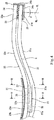
- Fig. 3 is an enlarged plan view showing the plate spring unit 20 shown in Fig. 1 and its vicinity.
- Fig. 4 is an enlarged side view showing the plate spring unit 20 shown in Fig. 2 and its vicinity.
- the plate spring unit 20 includes a lower plate spring 31, an upper plate spring 32, a middle spacer 33, and a pair of end spacers 34.
- the lower plate spring 31 is made of fiber-reinforced resin (for example, CFRP), and both longitudinal direction end portions 31b of the lower plate spring 31 are supported by the axle boxes 8 from below through the supporting members 22.
- the upper plate spring 32 is made of fiber-reinforced resin (for example, CFRP) and is arranged above the lower plate spring 31 with a gap.
- each of the lower plate spring 31 and the upper plate spring 32 has a constant thickness in the longitudinal direction. The thickness of the lower plate spring 31 and the thickness of the upper plate spring 32 are equal to each other.
- both the lower plate spring 31 and the upper plate spring 32 are made of fiber-reinforced resin, they do not necessarily have to be made of the same material.
- the upper plate spring 32 is made of CFRP, and a part of the lower plate spring 31 or the entire lower plate spring 31 is made of AFRP having excellent impact resistance, this is advantageous against collision with ballast or the like.
- the middle spacer 33 is sandwiched between a middle portion 31 a of the lower plate spring 31 and a middle portion 32a of the upper plate spring 32.
- Each of the end spacers 34 is sandwiched between the longitudinal direction end portion 31b of the lower plate spring 31 and a longitudinal direction end portion 32b of the upper plate spring 32.
- a gap G is formed between the middle spacer 33 and the end spacer 34.
- an intermediate portion 31c between the middle portion 31a and the end portion 31b in the lower plate spring 31 is in noncontact with an intermediate portion 32c between the middle portion 32a and the end portion 32b in the upper plate spring 32 with a gap G.
- each of the end portion 31b of the lower plate spring 31 and the end portion 32b of the upper plate spring 32 is inclined obliquely downward toward an outer side in the car longitudinal direction when the carbody 50 is not mounted on the bogie 1.
- a downward normal line NL perpendicular to lower surfaces of the end portions 31b and 32b of the lower and upper plate springs 31 and 32 is inclined (at an angle ⁇ ) from a vertical line VL toward a middle side in the car longitudinal direction when the carbody 50 is not mounted on the bogie 1.
- the lower plate spring 31 and the upper plate spring 32 bend, and with this, the normal line NL substantially coincides with the vertical line VL.
- each of the end portions 31b and 32b of the lower and upper plate springs 31 and 32 is formed linearly, and a length of this linear portion in the car longitudinal direction is longer than a length of the supporting member 22 in the car longitudinal direction.
- the end portion 31b of the lower plate spring 31, the end spacer 34, and the end portion 32b of the upper plate spring 32 overlap one another.
- the end portion 31b of the lower plate spring 31, the end spacer 34, the end portion 32b of the upper plate spring 32, the supporting member 22, and the axle box 8 are arranged at respective positions overlapping one another when viewed from a vertical direction.
- An upper surface of the receiving member 24 supports the lower surface of the end portion 31b of the lower plate spring 31.
- Each of the lower surface of the end portion 31b of the lower plate spring 31 and the corresponding upper surface of the receiving member 24 includes a flat surface.
- the receiving member 24 includes: a bottom wall portion 24a mounted on the seat member 23; an end wall portion 24b projecting upward from a car longitudinal direction outer side of the bottom wall portion 24a; and a pair of side wall portions 24c projecting upward from both respective car width direction sides of the bottom wall portion 24a.
- movements of the end portion 31b of the lower plate spring 31, the end spacer 34, and the end portion 32b of the upper plate spring 32 relative to the receiving member 24 toward the outer side in the car longitudinal direction by more than a predetermined distance are restricted by the end wall portion 24b.
- the interposed member 25 is inserted between the end portion 20b of the plate spring unit 20 and each of the bottom wall portion 24a, the end wall portion 24b, and the side wall portions 24c.
- the interposed member 25 is made of a material having lower hardness than the lower plate spring 31 and the upper plate spring 32, and for example, is made of an elastic material such as rubber.
- Each of at least a surface of the end spacer 34 which surface contacts the lower plate spring 31 and a surface of the end spacer 34 which surface contacts the upper plate spring 32 is made of a material having lower hardness than the lower plate spring 31 and the upper plate spring 32, and for example, is made of an elastic material such as rubber.
- the end spacer 34 just contacts the lower plate spring 31 and the upper plate spring 32 and is not bonded thereto. To be specific, when the plate spring unit 20 largely and elastically deforms, the end portion 32b of the upper plate spring 32 moves relative to the end portion 31b of the lower plate spring 31 toward the middle side in the longitudinal direction.
- the receiving member 24 is provided with a restricting member 26 configured to restrict a movement of the end spacer 34 relative to the axle box 8 toward the middle side in the car longitudinal direction by more than a predetermined distance.
- the restricting member 26 is provided between the lower plate spring 31 and the upper plate spring 32 so as to be located at a car longitudinal direction middle side of the end spacer 34.
- the restricting member 26 is attached to the side wall portions 24c of the receiving member 24. Further, the restricting member 26 projects from the side wall portions 24c in the car width direction so as to overlap the plate springs 31 and 32 in a plan view.
- the restricting member 26 is a rod-shaped member attached to the side wall portions 24c of the receiving member 24. The restricting member 26 is detachable from the receiving member 24 such that the plate spring unit 20 can be easily assembled to and detached from the receiving member 24.
- Each of the intermediate portion 31c of the lower plate spring 31 and the intermediate portion 32c of the upper plate spring 32 includes a region inclined relative to a horizontal direction in a side view. The region is inclined downward as it extends from the end portion 31b, 32b toward the middle portion 31a, 32a.
- each of the lower plate spring 31 and the upper plate spring 32 has an arc shape that is convex downward in a side view.
- the pressing member 21 includes: a main body portion 21a that is a rigid body made of metal, resin, or FRP, and includes a circular-arc lower surface that is convex downward; and a sheet portion 21b attached to the lower surface of the main body portion 21a.
- the sheet portion 21b is made of a material having lower hardness than the main body portion 21a of the pressing member 21 and the upper plate spring 32, and for example, is made of a rubber sheet.
- the middle portion 31a of the lower plate spring 31 and the middle portion 32a of the upper plate spring 32 sandwich the middle spacer 33 so as to be displaceable relative to each other in the longitudinal direction.
- the middle portion 31a of the lower plate spring 31, the middle spacer 33, the middle portion 32a of the upper plate spring 32, and the pressing member 21 are arranged at respective positions overlapping one another when viewed from the vertical direction.
- a length of the middle spacer 33 in the car longitudinal direction is shorter than that of the pressing member 21.
- Both car longitudinal direction end portions of the middle spacer 33 are located at the car longitudinal direction middle side of both car longitudinal direction end portions of the pressing member 21.
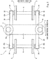
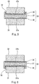
- Fig. 5 is a sectional view taken along line V-V of Fig. 4 .
- Fig. 6 is a sectional view taken along line VI-VI of Fig. 4 .
- each of at least a surface of the middle spacer 33 which surface contacts the lower plate spring 31 and a surface of the middle spacer 33 which surface contacts the upper plate spring 32 is made of a material having lower hardness than the lower plate spring 31 and the upper plate spring 32, and for example, is made of rubber.
- the middle spacer 33 includes: a lower elastic member 35 contacting an upper surface of the middle portion 31a of the lower plate spring 31; an upper elastic member 36 contacting a lower surface of the middle portion 32a of the upper plate spring 32; and a positioning member 37 sandwiched between the lower elastic member 35 and the upper elastic member 36.
- the middle spacer 33 just contacts the lower plate spring 31 and the upper plate spring 32 and is not bonded thereto.
- the positioning member 37 includes: a lower groove portion 37a that extends in the car longitudinal direction and is open downward; and an upper groove portion 37b that extends in the car longitudinal direction and is open upward.
- the positioning member 37 has an H-shaped section when viewed from the car longitudinal direction.
- the lower elastic member 35 and the lower plate spring 31 are fitted in the upper groove portion 37b from below, and the upper elastic member 36 and the upper plate spring 32 are fitted in the upper groove portion 37b from above.
- a bottom surface of the lower groove portion 37a has a circular-arc shape corresponding to an upper surface of the lower plate spring 31, and a bottom surface of the upper groove portion 37b has a circular-arc shape corresponding to a lower surface of the upper plate spring 32.
- An interposed member 38 is inserted between an inner side surface of the lower groove portion 37a and the lower plate spring 31, and an interposed member 39 is inserted between an inner side surface of the upper groove portion 37b and the upper plate spring 32.
- Each of the lower elastic member 35, the upper elastic member 36, and the interposed members 38 and 39 is made of a material having lower hardness than the lower plate spring 31 and the upper plate spring 32, and for example, is made of a rubber sheet.
- the fiber-reinforced resin lower plate spring 31 and the fiber-reinforced resin upper plate spring 32 are separately provided. Therefore, a step of bonding the lower plate spring 31 and the upper plate spring 32 is unnecessary, and this facilitates soundness check. Thus, production efficiency improves. Even if any one of the lower plate spring 31 and the upper plate spring 32 is damaged, the damaged plate spring is only required to be replaced. Thus, a maintenance cost can be reduced.
- the end spacer 34 and the end portion 32b of the upper plate spring 31 are arranged right above the end portion 31b of the lower plate spring 31 supported by the axle box 8 through the supporting member 22 from below. Therefore, even if the upper plate spring 32 is damaged, the axle box 8 can elastically support the cross beam 4 through the lower plate spring 31. Further, even if the lower plate spring 31 is damaged, the axle box 8 can elastically support the cross beam 4 through the upper plate spring 32. Therefore, even if any one of the lower plate spring 31 and the upper plate spring 32 is damaged, an elastic support function of the plate spring unit 20 is maintained. Thus, reliability improves.
- end portion 31b of the lower plate spring 31 and the end portion 32b of the upper plate spring 32 are displaceable relative to each other in the longitudinal direction through the end spacer 34. Therefore, a longitudinal direction tensile load or compressive load generated at the lower plate spring 31 and the upper plate spring 32 when the plate spring unit 20 elastically deforms can be reduced. Thus, lives of the plate springs 31 and 32 can be lengthened.
- each of the lower surface of the end portion 31b of the lower plate spring 31 and an upper surface of the bottom wall portion 24a of the receiving member 24 includes a flat surface. Therefore, when a load transmitted from the cross beam 4 to the plate spring unit 20 fluctuates, angular displacement of the end portion 31b of the lower plate spring 31 relative to the receiving member 24 in a side view hardly occurs, and shear force in the vertical direction is generated in the vicinity of the end portion 31b of the lower plate spring 31. However, since the end portion 32b of the upper plate spring 32 and the end portion 31b of the lower plate spring 31 overlap each other when viewed from the vertical direction, stress concentration on any one of the lower plate spring 31 and the upper plate spring 32 in the vicinity of the end portion of the plate spring unit 20 can be suppressed.
- the gap G is provided between the lower plate spring 31 and the upper plate spring 32 so as to be located at a region between the middle spacer 33 and the end spacer 34. Therefore, when the plate spring unit 20 elastically deforms, interference between the lower plate spring 31 and the upper plate spring 32 is prevented, and stress generated at the plate springs 31 and 32 is suppressed. Furthermore, relative positions of the middle portion 31a of the lower plate spring 31 and the middle portion 32a of the upper plate spring 32 are not fixed in the car longitudinal direction.
- the lower plate spring 31 is fitted in the lower groove portion 37a of the positioning member 37
- the upper plate spring 32 is fitted in the upper groove portion 37b of the positioning member 37. Therefore, relative positional displacement between the lower plate spring 31 and the upper plate spring 32 in the car width direction can be restricted by the positioning member 37. Furthermore, the lower groove portion 37a is open downward, and the upper groove portion 37b is open upward. Therefore, the plate spring unit 20 can be assembled by simply stacking the lower plate spring 31, the lower elastic member 35, the positioning member 37, the upper elastic member 36, and the upper plate spring 32. Thus, the plate spring unit 20 can be easily assembled and disassembled.
- the supporting member 22 is provided with the restricting member 26 configured to restrict the movement of the end spacer 34 relative to the axle box 8 toward the middle side in the car longitudinal direction by more than the predetermined distance. Therefore, the end spacer 34 can be prevented from falling without fixing the end spacer 34 to the lower plate spring 31 and the upper plate spring 32 by bonding or the like. Furthermore, since each of the middle spacer 33 and the end spacer 34 includes an elastic material such as rubber, appropriate damping performance can be given to the plate spring unit 20.
- Fig. 7 is an enlarged side view showing major components of a plate spring unit 120 of a bogie according to Embodiment 2.
- an end spacer 134 sandwiched between the end portion 31b of the lower plate spring 31 and the end portion 32b of the upper plate spring 32 has a three-layer structure including a lower plate 141, an intermediate plate 142, and an upper plate 143.
- Each of the lower plate 141 and the upper plate 143 is made of a material having lower hardness than the lower plate spring 31 and the upper plate spring 32, and for example, is made of an elastic material such as rubber.
- the intermediate plate 142 is made of metal, resin, FRP, or the like having higher hardness than the lower plate 141 and the upper plate 143.
- the lower plate 141 and the upper plate 143 are positioned relative to the intermediate plate 142 in the horizontal direction.
- the lower plate 141 and the intermediate plate 142 include a concave/convex fitting structure (not shown) that inhibits relative displacement between the lower plate 141 and the intermediate plate 142 in the horizontal direction.
- the upper plate 143 and the intermediate plate 142 also include a concave/convex fitting structure (not shown) that inhibits relative displacement between the upper plate 143 and the intermediate plate 142 in the horizontal direction.
- the intermediate plate 142 projects toward the longitudinal direction middle side of the lower plate 141 and the upper plate 143.
- the restricting member 26 provided at the receiving member 24 is arranged at a height that is opposed to the intermediate plate 142 in the horizontal direction.
- the restricting member 26 restricts a movement of the intermediate plate 142 relative to the axle box 8 toward the middle side in the car longitudinal direction by more than a predetermined distance.
- the restricting member 26 does not contact any of the lower plate 141 and the upper plate 143. Since the other configuration is the same as Embodiment 1, an explanation thereof is omitted.
- Fig. 8 is an enlarged side view showing major components of a plate spring unit 220 of a bogie according to Embodiment 3.
- the lower plate spring 31 and an upper plate spring 132 are different in thickness from each other.
- each of the lower plate spring 31 and the upper plate spring 132 has a constant thickness in the longitudinal direction.
- a thickness T1 of the lower plate spring 31 is larger than a thickness T2 of the upper plate spring 132. Only by changing the thicknesses of the plate springs 31 and 132 as above, the spring constant of the entire plate spring unit 220 can be easily changed.
- the spring constant of the entire plate spring unit 220 can be easily changed. Furthermore, by changing the materials of the plate springs 31 and 132, the spring constant of the entire plate spring unit 220 can be easily changed.
- the lower plate spring 31 and the upper plate spring 132 are separably stacked on the middle spacer 33 ( Fig. 4 ) and the end spacer 34 and are not bonded thereto. Therefore, only by changing a part of the plate springs (for example, only by changing the upper plate spring 132), the spring constant of the plate spring unit 220 can be easily adjusted.
- Fig. 9 is a plan view of a bogie 301 according to Embodiment 4.
- bearings (not shown) rotatably supporting the corresponding axle 5 are provided at the axle 5 so as to be located inside the corresponding wheels 6 in the car width direction, and each of the plate spring units 20 extending in the car longitudinal direction is provided between the axle box and the cross beam 4.
- the longitudinal direction middle portions of the plate spring units 20 support both respective car width direction side portions of the cross beam 4 from below, and the longitudinal direction end portions of the plate spring units 20 are supported by the respective axle boxes through the respective supporting members 22 from below.
- the bogie 301 may be called an inner frame type bogie. Since the other configuration is the same as Embodiment 1, an explanation thereof is omitted.
Landscapes
- Engineering & Computer Science (AREA)
- Mechanical Engineering (AREA)
- General Engineering & Computer Science (AREA)
- Springs (AREA)
- Vibration Prevention Devices (AREA)
Claims (6)
- Unité de ressort de plaque (20, 120, 220) pour un bogie de véhicule ferroviaire (1, 301), les deux parties d'extrémité (20b) dans la direction longitudinale de l'unité de ressort de plaque (20, 120, 220) étant supportées lors de l'utilisation par des boîtes d'essieu (8) respectives par-dessous, une partie centrale (20a) dans la direction longitudinale de l'unité de ressort de plaque (20, 120, 220) supportant lors de l'utilisation une traverse (4) par-dessous,
l'unité de ressort de plaque (20, 120, 220) comprenant :un ressort de plaque inférieur (31) comprenant les deux parties d'extrémité (31b) dans la direction longitudinale, supporté par les boîtes d'essieu (8) respectives par-dessous, le ressort de plaque inférieur (31) étant constitué de résine renforcée de fibres ;un ressort de plaque supérieur (32) disposé au-dessus du ressort de plaque inférieur (31) avec un espace et comprenant une partie centrale (32a) pressée par-dessus par un élément de pression (21) disposé au niveau de la traverse (4), le ressort de plaque supérieur (32) étant constitué de résine renforcée de fibres ;une entretoise centrale (33) prise en sandwich entre une partie centrale (31a) du ressort de plaque inférieur (31) et la partie centrale (32a) du ressort de plaque supérieur (32) ; etune entretoise d'extrémité (34, 134) prise en sandwich entre la partie d'extrémité (31b) du ressort de plaque inférieur (31) et une partie d'extrémité (32b) du ressort de plaque supérieur (32) de sorte que la partie d'extrémité (31b) du ressort de plaque inférieur (31), l'entretoise d'extrémité (34, 134) et la partie d'extrémité (32b) du ressort de plaque supérieur (32) soient empilées, et permettant un déplacement relatif entre la partie d'extrémité (31b) du ressort de plaque inférieur (31) et la partie d'extrémité (32b) du ressort de plaque supérieur (32) dans une direction longitudinale. - Unité de ressort de plaque (20, 120, 220) selon la revendication 1, la partie centrale (31a) du ressort de plaque inférieur (31) et la partie centrale (32a) du ressort de plaque supérieur (32) prenant en sandwich l'entretoise centrale (33) de sorte à pouvoir être déplacées l'une par rapport à l'autre dans la direction longitudinale.
- Unité de ressort de plaque (20, 120, 220) selon la revendication 1 ou 2 :l'entretoise centrale (33) comprenantune partie de rainure inférieure (37a) qui s'étend dans la direction longitudinale et est ouverte vers le bas etune partie de rainure supérieure (37b) qui s'étend dans la direction longitudinale et qui est ouverte vers le haut ; etle ressort de plaque inférieur (31) étant monté sur la partie de rainure inférieure (37a) par-dessous, et le ressort de plaque supérieur (32) étant monté sur la partie de rainure supérieure (37b) par-dessus.
- Bogie de véhicule ferroviaire (1, 301) comprenant :l'unité de ressort de plaque (20, 120, 220) selon l'une quelconque des revendications 1 à 3 ;la traverse (4) supportant une caisse (50) d'un véhicule ferroviaire ; etles boîtes d'essieu (8) disposées sur les deux côtés dans la direction longitudinale du véhicule de la traverse (4) et recevant les roulements (7) respectifs supportant un essieu (5),la boîte d'essieu (8), la partie d'extrémité (31b) du ressort de plaque inférieur (31), l'entretoise d'extrémité (34) et la partie d'extrémité (32b) du ressort de plaque supérieur (32) étant disposées à des positions respectives se chevauchant les unes les autres lorsqu'elles sont vues dans une direction verticale.
- Bogie de véhicule ferroviaire (1, 301) selon la revendication 4,
un élément de support (22) étant disposé au niveau d'une partie supérieure de la boîte d'essieu (8), l'élément de support (22) comprenant une surface supérieure supportant une surface inférieure de la partie d'extrémité (31b) du ressort de plaque inférieur (31) ; et
la surface inférieure de la partie terminale du ressort de plaque inférieur et la surface supérieure de l'élément de support comprenant des surfaces planes respectives. - Bogie de véhicule ferroviaire (1, 301) selon la revendication 4 ou 5, comprenant en outre un élément de restriction (26) disposé entre le ressort de plaque inférieur (31) et le ressort de plaque supérieur (32) de sorte à être situé au niveau d'un côté central dans la direction longitudinale du véhicule de l'entretoise d'extrémité (34), l'élément de restriction (26) limitant un mouvement de l'entretoise d'extrémité (34) par rapport à la boîte d'essieu (8) vers le côté central dans la direction longitudinale du véhicule de plus d'une distance prédéfinie.
Applications Claiming Priority (2)
| Application Number | Priority Date | Filing Date | Title |
|---|---|---|---|
| JP2015112945A JP6506630B2 (ja) | 2015-06-03 | 2015-06-03 | 板バネユニット及び鉄道車両用台車 |
| PCT/JP2016/002275 WO2016194302A1 (fr) | 2015-06-03 | 2016-05-10 | Unité de ressort de plaque et bogie de véhicule ferroviaire |
Publications (3)
| Publication Number | Publication Date |
|---|---|
| EP3306129A1 EP3306129A1 (fr) | 2018-04-11 |
| EP3306129A4 EP3306129A4 (fr) | 2019-01-16 |
| EP3306129B1 true EP3306129B1 (fr) | 2020-11-11 |
Family
ID=57440921
Family Applications (1)
| Application Number | Title | Priority Date | Filing Date |
|---|---|---|---|
| EP16802747.2A Active EP3306129B1 (fr) | 2015-06-03 | 2016-05-10 | Unité de ressort de plaque et bogie de véhicule ferroviaire |
Country Status (6)
| Country | Link |
|---|---|
| US (1) | US10723371B2 (fr) |
| EP (1) | EP3306129B1 (fr) |
| JP (1) | JP6506630B2 (fr) |
| KR (1) | KR102048504B1 (fr) |
| CN (1) | CN107532671B (fr) |
| WO (1) | WO2016194302A1 (fr) |
Families Citing this family (22)
| Publication number | Priority date | Publication date | Assignee | Title |
|---|---|---|---|---|
| WO2015098091A1 (fr) * | 2013-12-25 | 2015-07-02 | 川崎重工業株式会社 | Dispositif de mesure de charge destiné à un camion autorail |
| JP6506630B2 (ja) * | 2015-06-03 | 2019-04-24 | 川崎重工業株式会社 | 板バネユニット及び鉄道車両用台車 |
| JP6510938B2 (ja) * | 2015-09-10 | 2019-05-08 | 川崎重工業株式会社 | 鉄道車両用台車の電極付き板バネの製造方法 |
| JP6650352B2 (ja) * | 2016-06-21 | 2020-02-19 | 川崎重工業株式会社 | 鉄道車両台車の組立方法及びそれに用いる軸距固定治具 |
| US10286742B2 (en) * | 2017-06-12 | 2019-05-14 | GM Global Technology Operations LLC | Reinforcement plate for an auxiliary state leaf pack of a leaf spring system |
| JP6953904B2 (ja) * | 2017-08-29 | 2021-10-27 | いすゞ自動車株式会社 | 横置きリーフスプリング構造 |
| KR102518176B1 (ko) * | 2018-06-21 | 2023-04-06 | 현대자동차주식회사 | 다판 복합재스프링 서스펜션 |
| CN112298244A (zh) * | 2019-08-02 | 2021-02-02 | 中车唐山机车车辆有限公司 | 一种轨道车辆及其转向架 |
| CN112298241B (zh) * | 2019-08-02 | 2022-04-15 | 中车唐山机车车辆有限公司 | 转向架及轨道车辆 |
| CN112298253B (zh) * | 2019-08-02 | 2022-05-17 | 中车唐山机车车辆有限公司 | 一种转向架的侧梁 |
| CN112298249B (zh) * | 2019-08-02 | 2022-05-17 | 中车唐山机车车辆有限公司 | 转向架及轨道车辆 |
| CN112298251B (zh) * | 2019-08-02 | 2022-07-26 | 中车唐山机车车辆有限公司 | 一种转向架 |
| CN112298254B (zh) * | 2019-08-02 | 2022-05-17 | 中车唐山机车车辆有限公司 | 一种转向架的安装基础装置 |
| CN112298243B (zh) * | 2019-08-02 | 2022-05-17 | 中车唐山机车车辆有限公司 | 转向架及轨道车辆 |
| CN112644541B (zh) * | 2019-10-10 | 2022-07-26 | 中车唐山机车车辆有限公司 | 一系悬挂装置、转向架及轨道车辆 |
| CN112644549B (zh) * | 2019-10-10 | 2022-06-14 | 中车唐山机车车辆有限公司 | 转向架及轨道车辆 |
| JP2021104727A (ja) * | 2019-12-26 | 2021-07-26 | 川崎重工業株式会社 | 鉄道車両用台車の板バネの保護体及び鉄道車両用台車 |
| CN112550340B (zh) * | 2020-12-09 | 2022-05-17 | 中车唐山机车车辆有限公司 | 转向架及轨道车辆 |
| CN112519823B (zh) * | 2020-12-09 | 2022-01-07 | 中车唐山机车车辆有限公司 | 转向架侧梁、转向架及轨道车辆 |
| CN114084185B (zh) * | 2021-11-24 | 2023-04-28 | 中车唐山机车车辆有限公司 | 带有安全止挡的转向架及轨道车辆 |
| US12311714B1 (en) | 2024-05-31 | 2025-05-27 | Ford Global Technologies, Llc | Tension leaf with auxiliary spring |
| CN118877033B (zh) * | 2024-08-29 | 2025-10-31 | 中车青岛四方机车车辆股份有限公司 | 转向架的横梁组成、构架及转向架、轨道车辆 |
Family Cites Families (30)
| Publication number | Priority date | Publication date | Assignee | Title |
|---|---|---|---|---|
| US2304780A (en) * | 1941-03-26 | 1942-12-15 | Fries Otto H De | Vehicle spring |
| JPS5850338A (ja) * | 1981-09-19 | 1983-03-24 | Hino Motors Ltd | 重ね板ばね |
| JPS60132141A (ja) * | 1983-12-20 | 1985-07-15 | Nhk Spring Co Ltd | Frp板ばね装置 |
| DE3800587C1 (fr) * | 1988-01-12 | 1989-04-27 | Krupp Brueninghaus Gmbh, 5980 Werdohl, De | |
| FR2636110B1 (fr) * | 1988-09-02 | 1990-11-02 | Renault Vehicules Ind | Dispositif de fixation d'un ressort a lame en materiau composite |
| FR2782687B1 (fr) * | 1998-09-02 | 2003-01-10 | Alstom Technology | Bogie a longerons composites |
| FR2862935B1 (fr) * | 2003-12-02 | 2006-03-03 | Alstom | Dispositif de liaison souple entre un longeron et une boite d'essieu |
| JP5084539B2 (ja) | 2008-02-06 | 2012-11-28 | 中央発條株式会社 | 重ね板ばね用のサイレンサーおよびそのサイレンサーを用いた重ね板ばね |
| CN202032028U (zh) * | 2011-03-30 | 2011-11-09 | 北汽福田汽车股份有限公司 | 板簧组件和具有该板簧组件的车辆悬架系统 |
| JP5433080B2 (ja) | 2011-04-07 | 2014-03-05 | 川崎重工業株式会社 | 鉄道車両用台車 |
| US9358989B2 (en) * | 2011-07-14 | 2016-06-07 | Kawasaki Jukogyo Kabushiki Kaisha | Railcar bogie |
| JP5947590B2 (ja) * | 2011-07-14 | 2016-07-06 | 川崎重工業株式会社 | 鉄道車両用台車 |
| KR101602388B1 (ko) * | 2011-09-15 | 2016-03-10 | 가부시키가이샤 지에이치 크래프트 | 철도 차량 대차용 판 스프링 |
| KR101301916B1 (ko) | 2011-10-10 | 2013-08-30 | 주식회사 아주산업 | 문구용 투명 케이스 및 그 제조 방법 |
| JP5878791B2 (ja) * | 2012-02-29 | 2016-03-08 | 川崎重工業株式会社 | 板バネユニット及びそれを用いた鉄道車両用台車 |
| JP5779280B2 (ja) * | 2012-04-06 | 2015-09-16 | 川崎重工業株式会社 | 鉄道車両用台車 |
| US9352757B2 (en) * | 2012-04-06 | 2016-05-31 | Kawasaki Jukogyo Kabushiki Kaisha | Railcar bogie |
| JP5438796B2 (ja) * | 2012-04-06 | 2014-03-12 | 川崎重工業株式会社 | 鉄道車両用台車及びそれを備えた鉄道車両 |
| CN104822576B (zh) * | 2013-01-10 | 2017-03-15 | 川崎重工业株式会社 | 铁道车辆用转向架 |
| JP6110669B2 (ja) * | 2013-01-10 | 2017-04-05 | 川崎重工業株式会社 | 鉄道車両用台車及びそれを備えた鉄道車両 |
| JP6068984B2 (ja) * | 2013-01-10 | 2017-01-25 | 川崎重工業株式会社 | 鉄道車両用台車 |
| JP6088366B2 (ja) | 2013-06-19 | 2017-03-01 | 川崎重工業株式会社 | 板バネカバー及びそれを備えた鉄道車両用台車 |
| JP6247494B2 (ja) * | 2013-10-09 | 2017-12-13 | 川崎重工業株式会社 | 鉄道車両台車用の板バネの製造方法 |
| CN203570900U (zh) * | 2013-12-03 | 2014-04-30 | 山东方成汽车悬架科技有限公司 | 少片簧端部降噪装置 |
| JP6111187B2 (ja) * | 2013-12-05 | 2017-04-05 | 川崎重工業株式会社 | 鉄道車両用軸箱支持装置 |
| WO2015098091A1 (fr) * | 2013-12-25 | 2015-07-02 | 川崎重工業株式会社 | Dispositif de mesure de charge destiné à un camion autorail |
| CN203743275U (zh) * | 2013-12-31 | 2014-07-30 | 重庆红岩方大汽车悬架有限公司 | 汽车钢板弹簧 |
| JP6383282B2 (ja) * | 2014-12-17 | 2018-08-29 | 川崎重工業株式会社 | 鉄道車両用台車 |
| JP6506630B2 (ja) * | 2015-06-03 | 2019-04-24 | 川崎重工業株式会社 | 板バネユニット及び鉄道車両用台車 |
| JP6944765B2 (ja) * | 2016-05-16 | 2021-10-06 | 川崎重工業株式会社 | 鉄道車両台車の組立方法、測定治具及び鉄道車両台車 |
-
2015
- 2015-06-03 JP JP2015112945A patent/JP6506630B2/ja active Active
-
2016
- 2016-05-10 CN CN201680025581.1A patent/CN107532671B/zh active Active
- 2016-05-10 US US15/579,451 patent/US10723371B2/en active Active
- 2016-05-10 KR KR1020177037606A patent/KR102048504B1/ko not_active Expired - Fee Related
- 2016-05-10 EP EP16802747.2A patent/EP3306129B1/fr active Active
- 2016-05-10 WO PCT/JP2016/002275 patent/WO2016194302A1/fr not_active Ceased
Non-Patent Citations (1)
| Title |
|---|
| None * |
Also Published As
| Publication number | Publication date |
|---|---|
| JP2016223602A (ja) | 2016-12-28 |
| EP3306129A1 (fr) | 2018-04-11 |
| US10723371B2 (en) | 2020-07-28 |
| CN107532671A (zh) | 2018-01-02 |
| EP3306129A4 (fr) | 2019-01-16 |
| KR20180014062A (ko) | 2018-02-07 |
| KR102048504B1 (ko) | 2019-11-26 |
| JP6506630B2 (ja) | 2019-04-24 |
| CN107532671B (zh) | 2019-09-24 |
| WO2016194302A1 (fr) | 2016-12-08 |
| US20180141573A1 (en) | 2018-05-24 |
Similar Documents
| Publication | Publication Date | Title |
|---|---|---|
| EP3306129B1 (fr) | Unité de ressort de plaque et bogie de véhicule ferroviaire | |
| US9573604B2 (en) | Railcar bogie | |
| US9376127B2 (en) | Railcar bogie | |
| US8656839B2 (en) | Railcar bogie | |
| US9352757B2 (en) | Railcar bogie | |
| US9802627B2 (en) | Railcar bogie | |
| CN105143012B (zh) | 铁道车辆用转向架 | |
| EP2835301B1 (fr) | Bogie de véhicule ferroviaire et véhicule le compartant | |
| CN104487312A (zh) | 铁道车辆用转向架 | |
| US20220281492A1 (en) | Railroad vehicle | |
| KR102468623B1 (ko) | 축박스 서스펜션장치 및 이를 구비한 보기대차 | |
| US10875552B2 (en) | Railcar bogie | |
| US20200231188A1 (en) | Railcar bogie frame and bogie including same | |
| CN214420462U (zh) | 轨道车辆、转向架及其轴箱悬挂装置 | |
| CN112849191A (zh) | 轨道车辆、转向架及其轴箱悬挂装置 | |
| JP6991661B2 (ja) | 鉄道車両の車体支持装置 |
Legal Events
| Date | Code | Title | Description |
|---|---|---|---|
| STAA | Information on the status of an ep patent application or granted ep patent |
Free format text: STATUS: THE INTERNATIONAL PUBLICATION HAS BEEN MADE |
|
| PUAI | Public reference made under article 153(3) epc to a published international application that has entered the european phase |
Free format text: ORIGINAL CODE: 0009012 |
|
| STAA | Information on the status of an ep patent application or granted ep patent |
Free format text: STATUS: REQUEST FOR EXAMINATION WAS MADE |
|
| 17P | Request for examination filed |
Effective date: 20180103 |
|
| AK | Designated contracting states |
Kind code of ref document: A1 Designated state(s): AL AT BE BG CH CY CZ DE DK EE ES FI FR GB GR HR HU IE IS IT LI LT LU LV MC MK MT NL NO PL PT RO RS SE SI SK SM TR |
|
| AX | Request for extension of the european patent |
Extension state: BA ME |
|
| DAV | Request for validation of the european patent (deleted) | ||
| DAX | Request for extension of the european patent (deleted) | ||
| A4 | Supplementary search report drawn up and despatched |
Effective date: 20181214 |
|
| RIC1 | Information provided on ipc code assigned before grant |
Ipc: F16F 1/30 20060101ALI20181210BHEP Ipc: B61F 5/52 20060101ALI20181210BHEP Ipc: B61F 5/30 20060101ALI20181210BHEP Ipc: F16F 1/18 20060101AFI20181210BHEP |
|
| GRAP | Despatch of communication of intention to grant a patent |
Free format text: ORIGINAL CODE: EPIDOSNIGR1 |
|
| STAA | Information on the status of an ep patent application or granted ep patent |
Free format text: STATUS: GRANT OF PATENT IS INTENDED |
|
| INTG | Intention to grant announced |
Effective date: 20200519 |
|
| GRAS | Grant fee paid |
Free format text: ORIGINAL CODE: EPIDOSNIGR3 |
|
| GRAA | (expected) grant |
Free format text: ORIGINAL CODE: 0009210 |
|
| STAA | Information on the status of an ep patent application or granted ep patent |
Free format text: STATUS: THE PATENT HAS BEEN GRANTED |
|
| AK | Designated contracting states |
Kind code of ref document: B1 Designated state(s): AL AT BE BG CH CY CZ DE DK EE ES FI FR GB GR HR HU IE IS IT LI LT LU LV MC MK MT NL NO PL PT RO RS SE SI SK SM TR |
|
| REG | Reference to a national code |
Ref country code: GB Ref legal event code: FG4D |
|
| REG | Reference to a national code |
Ref country code: CH Ref legal event code: EP |
|
| REG | Reference to a national code |
Ref country code: AT Ref legal event code: REF Ref document number: 1333779 Country of ref document: AT Kind code of ref document: T Effective date: 20201115 |
|
| REG | Reference to a national code |
Ref country code: DE Ref legal event code: R096 Ref document number: 602016047751 Country of ref document: DE |
|
| REG | Reference to a national code |
Ref country code: IE Ref legal event code: FG4D |
|
| REG | Reference to a national code |
Ref country code: NL Ref legal event code: MP Effective date: 20201111 |
|
| REG | Reference to a national code |
Ref country code: AT Ref legal event code: MK05 Ref document number: 1333779 Country of ref document: AT Kind code of ref document: T Effective date: 20201111 |
|
| PG25 | Lapsed in a contracting state [announced via postgrant information from national office to epo] |
Ref country code: GR Free format text: LAPSE BECAUSE OF FAILURE TO SUBMIT A TRANSLATION OF THE DESCRIPTION OR TO PAY THE FEE WITHIN THE PRESCRIBED TIME-LIMIT Effective date: 20210212 Ref country code: FI Free format text: LAPSE BECAUSE OF FAILURE TO SUBMIT A TRANSLATION OF THE DESCRIPTION OR TO PAY THE FEE WITHIN THE PRESCRIBED TIME-LIMIT Effective date: 20201111 Ref country code: RS Free format text: LAPSE BECAUSE OF FAILURE TO SUBMIT A TRANSLATION OF THE DESCRIPTION OR TO PAY THE FEE WITHIN THE PRESCRIBED TIME-LIMIT Effective date: 20201111 Ref country code: PT Free format text: LAPSE BECAUSE OF FAILURE TO SUBMIT A TRANSLATION OF THE DESCRIPTION OR TO PAY THE FEE WITHIN THE PRESCRIBED TIME-LIMIT Effective date: 20210311 Ref country code: NO Free format text: LAPSE BECAUSE OF FAILURE TO SUBMIT A TRANSLATION OF THE DESCRIPTION OR TO PAY THE FEE WITHIN THE PRESCRIBED TIME-LIMIT Effective date: 20210211 |
|
| PG25 | Lapsed in a contracting state [announced via postgrant information from national office to epo] |
Ref country code: SE Free format text: LAPSE BECAUSE OF FAILURE TO SUBMIT A TRANSLATION OF THE DESCRIPTION OR TO PAY THE FEE WITHIN THE PRESCRIBED TIME-LIMIT Effective date: 20201111 Ref country code: BG Free format text: LAPSE BECAUSE OF FAILURE TO SUBMIT A TRANSLATION OF THE DESCRIPTION OR TO PAY THE FEE WITHIN THE PRESCRIBED TIME-LIMIT Effective date: 20210211 Ref country code: PL Free format text: LAPSE BECAUSE OF FAILURE TO SUBMIT A TRANSLATION OF THE DESCRIPTION OR TO PAY THE FEE WITHIN THE PRESCRIBED TIME-LIMIT Effective date: 20201111 Ref country code: LV Free format text: LAPSE BECAUSE OF FAILURE TO SUBMIT A TRANSLATION OF THE DESCRIPTION OR TO PAY THE FEE WITHIN THE PRESCRIBED TIME-LIMIT Effective date: 20201111 Ref country code: IS Free format text: LAPSE BECAUSE OF FAILURE TO SUBMIT A TRANSLATION OF THE DESCRIPTION OR TO PAY THE FEE WITHIN THE PRESCRIBED TIME-LIMIT Effective date: 20210311 Ref country code: AT Free format text: LAPSE BECAUSE OF FAILURE TO SUBMIT A TRANSLATION OF THE DESCRIPTION OR TO PAY THE FEE WITHIN THE PRESCRIBED TIME-LIMIT Effective date: 20201111 |
|
| REG | Reference to a national code |
Ref country code: LT Ref legal event code: MG9D |
|
| PG25 | Lapsed in a contracting state [announced via postgrant information from national office to epo] |
Ref country code: HR Free format text: LAPSE BECAUSE OF FAILURE TO SUBMIT A TRANSLATION OF THE DESCRIPTION OR TO PAY THE FEE WITHIN THE PRESCRIBED TIME-LIMIT Effective date: 20201111 |
|
| PG25 | Lapsed in a contracting state [announced via postgrant information from national office to epo] |
Ref country code: SM Free format text: LAPSE BECAUSE OF FAILURE TO SUBMIT A TRANSLATION OF THE DESCRIPTION OR TO PAY THE FEE WITHIN THE PRESCRIBED TIME-LIMIT Effective date: 20201111 Ref country code: LT Free format text: LAPSE BECAUSE OF FAILURE TO SUBMIT A TRANSLATION OF THE DESCRIPTION OR TO PAY THE FEE WITHIN THE PRESCRIBED TIME-LIMIT Effective date: 20201111 Ref country code: CZ Free format text: LAPSE BECAUSE OF FAILURE TO SUBMIT A TRANSLATION OF THE DESCRIPTION OR TO PAY THE FEE WITHIN THE PRESCRIBED TIME-LIMIT Effective date: 20201111 Ref country code: EE Free format text: LAPSE BECAUSE OF FAILURE TO SUBMIT A TRANSLATION OF THE DESCRIPTION OR TO PAY THE FEE WITHIN THE PRESCRIBED TIME-LIMIT Effective date: 20201111 Ref country code: RO Free format text: LAPSE BECAUSE OF FAILURE TO SUBMIT A TRANSLATION OF THE DESCRIPTION OR TO PAY THE FEE WITHIN THE PRESCRIBED TIME-LIMIT Effective date: 20201111 Ref country code: SK Free format text: LAPSE BECAUSE OF FAILURE TO SUBMIT A TRANSLATION OF THE DESCRIPTION OR TO PAY THE FEE WITHIN THE PRESCRIBED TIME-LIMIT Effective date: 20201111 |
|
| PGFP | Annual fee paid to national office [announced via postgrant information from national office to epo] |
Ref country code: FR Payment date: 20210520 Year of fee payment: 6 Ref country code: DE Payment date: 20210624 Year of fee payment: 6 |
|
| REG | Reference to a national code |
Ref country code: DE Ref legal event code: R097 Ref document number: 602016047751 Country of ref document: DE |
|
| PG25 | Lapsed in a contracting state [announced via postgrant information from national office to epo] |
Ref country code: DK Free format text: LAPSE BECAUSE OF FAILURE TO SUBMIT A TRANSLATION OF THE DESCRIPTION OR TO PAY THE FEE WITHIN THE PRESCRIBED TIME-LIMIT Effective date: 20201111 |
|
| PGFP | Annual fee paid to national office [announced via postgrant information from national office to epo] |
Ref country code: TR Payment date: 20210504 Year of fee payment: 6 |
|
| PLBE | No opposition filed within time limit |
Free format text: ORIGINAL CODE: 0009261 |
|
| STAA | Information on the status of an ep patent application or granted ep patent |
Free format text: STATUS: NO OPPOSITION FILED WITHIN TIME LIMIT |
|
| 26N | No opposition filed |
Effective date: 20210812 |
|
| PG25 | Lapsed in a contracting state [announced via postgrant information from national office to epo] |
Ref country code: IT Free format text: LAPSE BECAUSE OF FAILURE TO SUBMIT A TRANSLATION OF THE DESCRIPTION OR TO PAY THE FEE WITHIN THE PRESCRIBED TIME-LIMIT Effective date: 20201111 Ref country code: AL Free format text: LAPSE BECAUSE OF FAILURE TO SUBMIT A TRANSLATION OF THE DESCRIPTION OR TO PAY THE FEE WITHIN THE PRESCRIBED TIME-LIMIT Effective date: 20201111 Ref country code: NL Free format text: LAPSE BECAUSE OF FAILURE TO SUBMIT A TRANSLATION OF THE DESCRIPTION OR TO PAY THE FEE WITHIN THE PRESCRIBED TIME-LIMIT Effective date: 20201111 |
|
| PG25 | Lapsed in a contracting state [announced via postgrant information from national office to epo] |
Ref country code: SI Free format text: LAPSE BECAUSE OF FAILURE TO SUBMIT A TRANSLATION OF THE DESCRIPTION OR TO PAY THE FEE WITHIN THE PRESCRIBED TIME-LIMIT Effective date: 20201111 |
|
| REG | Reference to a national code |
Ref country code: CH Ref legal event code: PL |
|
| GBPC | Gb: european patent ceased through non-payment of renewal fee |
Effective date: 20210510 |
|
| PG25 | Lapsed in a contracting state [announced via postgrant information from national office to epo] |
Ref country code: ES Free format text: LAPSE BECAUSE OF FAILURE TO SUBMIT A TRANSLATION OF THE DESCRIPTION OR TO PAY THE FEE WITHIN THE PRESCRIBED TIME-LIMIT Effective date: 20201111 Ref country code: CH Free format text: LAPSE BECAUSE OF NON-PAYMENT OF DUE FEES Effective date: 20210531 Ref country code: MC Free format text: LAPSE BECAUSE OF FAILURE TO SUBMIT A TRANSLATION OF THE DESCRIPTION OR TO PAY THE FEE WITHIN THE PRESCRIBED TIME-LIMIT Effective date: 20201111 Ref country code: LU Free format text: LAPSE BECAUSE OF NON-PAYMENT OF DUE FEES Effective date: 20210510 Ref country code: LI Free format text: LAPSE BECAUSE OF NON-PAYMENT OF DUE FEES Effective date: 20210531 |
|
| REG | Reference to a national code |
Ref country code: BE Ref legal event code: MM Effective date: 20210531 |
|
| PG25 | Lapsed in a contracting state [announced via postgrant information from national office to epo] |
Ref country code: IE Free format text: LAPSE BECAUSE OF NON-PAYMENT OF DUE FEES Effective date: 20210510 Ref country code: GB Free format text: LAPSE BECAUSE OF NON-PAYMENT OF DUE FEES Effective date: 20210510 |
|
| PG25 | Lapsed in a contracting state [announced via postgrant information from national office to epo] |
Ref country code: IS Free format text: LAPSE BECAUSE OF FAILURE TO SUBMIT A TRANSLATION OF THE DESCRIPTION OR TO PAY THE FEE WITHIN THE PRESCRIBED TIME-LIMIT Effective date: 20210311 |
|
| PG25 | Lapsed in a contracting state [announced via postgrant information from national office to epo] |
Ref country code: BE Free format text: LAPSE BECAUSE OF NON-PAYMENT OF DUE FEES Effective date: 20210531 |
|
| REG | Reference to a national code |
Ref country code: DE Ref legal event code: R119 Ref document number: 602016047751 Country of ref document: DE |
|
| PG25 | Lapsed in a contracting state [announced via postgrant information from national office to epo] |
Ref country code: FR Free format text: LAPSE BECAUSE OF NON-PAYMENT OF DUE FEES Effective date: 20220531 |
|
| PG25 | Lapsed in a contracting state [announced via postgrant information from national office to epo] |
Ref country code: DE Free format text: LAPSE BECAUSE OF NON-PAYMENT OF DUE FEES Effective date: 20221201 |
|
| PG25 | Lapsed in a contracting state [announced via postgrant information from national office to epo] |
Ref country code: CY Free format text: LAPSE BECAUSE OF FAILURE TO SUBMIT A TRANSLATION OF THE DESCRIPTION OR TO PAY THE FEE WITHIN THE PRESCRIBED TIME-LIMIT Effective date: 20201111 |
|
| PG25 | Lapsed in a contracting state [announced via postgrant information from national office to epo] |
Ref country code: HU Free format text: LAPSE BECAUSE OF FAILURE TO SUBMIT A TRANSLATION OF THE DESCRIPTION OR TO PAY THE FEE WITHIN THE PRESCRIBED TIME-LIMIT; INVALID AB INITIO Effective date: 20160510 |
|
| PG25 | Lapsed in a contracting state [announced via postgrant information from national office to epo] |
Ref country code: MK Free format text: LAPSE BECAUSE OF FAILURE TO SUBMIT A TRANSLATION OF THE DESCRIPTION OR TO PAY THE FEE WITHIN THE PRESCRIBED TIME-LIMIT Effective date: 20201111 |
|
| PG25 | Lapsed in a contracting state [announced via postgrant information from national office to epo] |
Ref country code: MT Free format text: LAPSE BECAUSE OF FAILURE TO SUBMIT A TRANSLATION OF THE DESCRIPTION OR TO PAY THE FEE WITHIN THE PRESCRIBED TIME-LIMIT Effective date: 20201111 |