EP3306392A1 - Système d'éclairage et appareil de projection - Google Patents
Système d'éclairage et appareil de projection Download PDFInfo
- Publication number
- EP3306392A1 EP3306392A1 EP16192627.4A EP16192627A EP3306392A1 EP 3306392 A1 EP3306392 A1 EP 3306392A1 EP 16192627 A EP16192627 A EP 16192627A EP 3306392 A1 EP3306392 A1 EP 3306392A1
- Authority
- EP
- European Patent Office
- Prior art keywords
- light source
- excitation
- wavelength conversion
- dichroic element
- disposed
- Prior art date
- Legal status (The legal status is an assumption and is not a legal conclusion. Google has not performed a legal analysis and makes no representation as to the accuracy of the status listed.)
- Granted
Links
Images






Classifications
-
- G—PHYSICS
- G03—PHOTOGRAPHY; CINEMATOGRAPHY; ANALOGOUS TECHNIQUES USING WAVES OTHER THAN OPTICAL WAVES; ELECTROGRAPHY; HOLOGRAPHY
- G03B—APPARATUS OR ARRANGEMENTS FOR TAKING PHOTOGRAPHS OR FOR PROJECTING OR VIEWING THEM; APPARATUS OR ARRANGEMENTS EMPLOYING ANALOGOUS TECHNIQUES USING WAVES OTHER THAN OPTICAL WAVES; ACCESSORIES THEREFOR
- G03B21/00—Projectors or projection-type viewers; Accessories therefor
- G03B21/14—Details
- G03B21/20—Lamp housings
- G03B21/2006—Lamp housings characterised by the light source
- G03B21/2033—LED or laser light sources
- G03B21/204—LED or laser light sources using secondary light emission, e.g. luminescence or fluorescence
-
- G—PHYSICS
- G03—PHOTOGRAPHY; CINEMATOGRAPHY; ANALOGOUS TECHNIQUES USING WAVES OTHER THAN OPTICAL WAVES; ELECTROGRAPHY; HOLOGRAPHY
- G03B—APPARATUS OR ARRANGEMENTS FOR TAKING PHOTOGRAPHS OR FOR PROJECTING OR VIEWING THEM; APPARATUS OR ARRANGEMENTS EMPLOYING ANALOGOUS TECHNIQUES USING WAVES OTHER THAN OPTICAL WAVES; ACCESSORIES THEREFOR
- G03B21/00—Projectors or projection-type viewers; Accessories therefor
- G03B21/14—Details
- G03B21/20—Lamp housings
- G03B21/2006—Lamp housings characterised by the light source
- G03B21/2013—Plural light sources
Definitions
- the invention relates to an illumination system, and more particularly to an illumination system and a projection apparatus equipped with the illumination system having a wavelength conversion element.
- the projector with the solid-state light source has the following three types of light source systems: lasers, light emitting diodes (LEDs), and a combination of laser and light emitting diodes.
- Laser light source system usually uses blue laser with fluorescence wheel or phosphor wheel, and the fluorescent wheel contains phosphor layer for exciting red beam or phosphor layer for exciting green beam.
- LED light source system usually comprises a light emitting diode module for emitting red light, a light emitting diode module for emitting green light and a light emitting diode module for emitting blue light.
- the light source system with a combination of laser and light emitting diodes usually uses blue laser with fluorescence wheel, wherein the fluorescent wheel contains phosphor for exciting red beam or phosphor for exciting green beam, and the beam with the rest colors are emitted by light emitting diode or laser with specified wavelengths.
- the existing technology uses dichroic mirror to combine the red, green and blue beams provided by the respective light source modules.
- dichroic mirror due to the physical limitation of the dichroic mirror, only one of the red, green or blue light source modules is selected to use. Therefore, when the brightness of image display needs to enhance, either the power of each light source module or the quantity of laser or light emitting diodes in each light source module is required to increase.
- the aforementioned approaches may lead to the following problems: (1) the photoelectric conversion efficiency decreases if simply increasing the power of the light source module, further, the increase in power may disproportionate to the increase in the brightness and the brightness may be saturated; and therefore, the brightness may not be enhanced by indefinitely increasing the power; (2) the component size of the light source system may increase and the entire volume of the light source system may become large if simply increasing the quantity of laser or light emitting diodes; (3) the etendue may increase if simply increasing the quantity of laser or light emitting diodes, and the brightness may not be able to enhance any longer by increasing the quantity of laser or light emitting diodes if the etendue has a mismatch with the designing configuration of the projector or the etendue reaches to the maximum.
- One object of the invention is to provide an illumination system able to enhance the optical power of the beam provided by the illumination system.
- Another object of the invention is to provide an illumination system including three light source assemblies with various colors, and the illumination system has enhanced optical power of the beam provided by the illumination system.
- Still another object of the invention is to provide an illumination system having enhanced optical power of the wavelength conversion beam without increasing the light etendue; and consequentially, a projection apparatus using the illumination system has enhanced brightness of the images projected onto a screen.
- the invention provides a projection apparatus comprising a first light source assembly.
- the first light source assembly comprises a first excitation light source, a second excitation light source, a first dichroic element, a first wavelength conversion element, a first collimating element and a second collimating element.
- the first excitation light source is configured to provide a first excitation beam.
- the second excitation light source is configured to provide a second excitation beam.
- the first excitation beam and the second excitation beam have the same color.
- the first dichroic element is disposed between the first excitation light source and the second excitation light source. The second excitation beam is transmitted toward the first excitation light source through the first dichroic element.
- the first wavelength conversion element is disposed between the first excitation light source and the first dichroic element.
- the first wavelength conversion element is configured to convert the first excitation beam and the second excitation beam into a first wavelength conversion beam and transmit the first wavelength conversion beam toward the first dichroic element.
- the first collimating element is disposed between the first wavelength conversion element and the first dichroic element.
- the second collimating element is disposed between the second excitation light source and the first dichroic element.
- FIG. 1 is a schematic view of an illumination system in accordance with an embodiment of the invention.
- the illumination system 10 of the embodiment includes a light source assembly 100.
- the light source assembly 100 includes a first excitation light source 110, a second excitation light source 120, a dichroic element 130, a wavelength conversion element 140, a first collimating element 150 and a second collimating element 160.
- the first excitation light source 110 is configured to provide a first excitation beam C1;
- the second excitation light source 120 is configured to provide a second excitation beam C2; and the first excitation beam C1 and the second excitation beam C2 have the same color, such as blue, for example.
- the wavelengths of the first excitation beam C1 and the second excitation beam C2 may be located within a certain range, for example, located within in a range 450 ⁇ 475 nm if the two beams are blue.
- the dichroic element 130 is disposed between the first excitation light source 110 and the second excitation light source 120.
- the dichroic element 130 is a dichroic mirror, through which the second excitation beam C2 is transmitted toward the first excitation light source 110.
- the wavelength conversion element 140 is disposed between the first excitation light source 110 and the dichroic element 130.
- the wavelength conversion element 140 is configured to convert the first excitation beam C1 and the second excitation beam C2 into a wavelength conversion beam D and transmit the wavelength conversion beam D toward the dichroic element 130.
- the first collimating element 150 is disposed between the wavelength conversion element 140 and the dichroic element 130.
- the second collimating element 160 is disposed between the second excitation light source 120 and the dichroic element 130.
- the wavelength conversion element 140 and the first excitation light source 110 are two separated elements and have a preset distance apart from each other; wherein the preset distance is not greater than the distance between the wavelength conversion element 140 and the dichroic element 130.
- the first excitation light source 110 may be a light emitting diode, a laser light source or other suitable light source.
- the second excitation light source 120 may be a light emitting diode, a laser light source or other suitable source.
- a first excitation light source 110 may be a light emitting diode chip or a laser diode chip. The structures of the first excitation light source 110 and the second excitation light source 120 may be the same or not.
- the wavelength conversion element 140 has a wavelength conversion material layer 141 and a dichroic layer 142.
- the dichroic layer 142 is disposed on the wavelength conversion material layer 141 and adjacent to the first excitation light source 110. In other words, the dichroic layer 142 is disposed between the wavelength conversion material layer 141 and the first excitation light source 110.
- the wavelength conversion material layer 141 includes wavelength conversion material such as fluorescent powder or phosphor powder, but the invention is not limited thereto.
- the surfaces of the wavelength conversion material layer 141 are configured to absorb the first excitation beam C1 and the second excitation beam C2, and the wavelength conversion material layer 141 emits the wavelength conversion beam D to the dichroic element 130.
- the first excitation beam C1 may pass through the dichroic layer 142 and then is transmitted to the wavelength conversion material layer 141.
- the wavelength conversion beam D emitted from the wavelength conversion material may be transmitted toward various directions; that is, a portion of the wavelength conversion beam D is transmitted toward the dichroic element 130 and a portion of the wavelength conversion beam D is transmitted toward the dichroic layer 142. Therefore, by using the dichroic layer 142 to reflect the wavelength conversion beam D transmitting toward the dichroic layer 142 so as to direct the wavelength conversion beam D to transmit toward the dichroic element 130, the total optical output of the wavelength conversion beam D transmitting to the dichroic element 130 is increased.
- the first excitation light source 110 and the second excitation light source 120 are disposed on the two sides of the dichroic element 130, respectively.
- the second excitation beam C2 may pass through the dichroic element 130 and the wavelength conversion beam D may be reflected by the dichroic element 130. After passing through the dichroic element 130, the second excitation beam C2 is transmitted to one side of the wavelength conversion material layer 141 facing the dichroic element 130. After passing through the dichroic layer 142, the first excitation beam C1 is transmitted to one side of the wavelength conversion material layer 141 facing the dichroic layer 142.
- the output of the wavelength conversion beam D is enhanced without increasing the light etendue.
- the first collimating element 150 and the second collimating element 160 may have the same configuration.
- the first collimating element 150 includes a collimating lens 151 and a lens 152.
- the lens 152 is disposed between the collimating lens 151 and the dichroic element 130.
- the second collimating element 160 includes a collimating lens 161 and a lens 162.
- the lens 162 is disposed between the collimating lens 161 and the dichroic element 130.
- the collimating lenses 151, 161 have the same shape and the lenses 152, 162 have the same shape.
- the specified configurations of the first collimating element 150 and the second collimating element 160 as well as the quantities of the collimating lens and lens therein are not limited in the invention. Namely, a designer may provide collimating lens and lens with different structures and quantities in response to actual requirements. Further, the optical distance of the second excitation beam C2 from the second excitation light source 120 to the dichroic element 130 is equal to the optical distance of the wavelength conversion beam D from the wavelength conversion element 140 to the dichroic element 130.
- the facula of the second excitation beam C2 on the wavelength conversion element 140 is similar to that of the second excitation beam C2 on the light-exiting surface 121 of the second excitation light source 120.
- the shape and area size of the light-exiting surface 121 of the second excitation light source 120 are same as those of the light-exiting surface 143 of the wavelength conversion element 140, respectively. Therefore, the second excitation beam C2 may substantially cover the entire wavelength conversion element 140, thereby improving light utilization and avoiding light losses.
- the color configuration of the first excitation beam C1, the second excitation beam C2 and the wavelength conversion beam D may be determined according to actual requirements.
- the color configuration may be selected from one of: (1) both of the first excitation beam C1 and the second excitation beam C2 are blue light, and the wavelength conversion beam D is green light; (2) both of the first excitation beam C1 and the second excitation beam C2 are blue light, and the wavelength conversion beam D is red light; (3) both of the first excitation beam C 1 and the second excitation beam C2 are blue light, and the wavelength conversion beam D is yellow light; and (4) both of the first excitation beam C 1 and the second excitation beam C2 are ultraviolet light, and the wavelength conversion beam D is white light.
- the illumination system 10 of the embodiment may further include other optical element(s), which is disposed on the transmission path of the wavelength conversion beam D after passing through the dichroic element 130.
- the optical element may include a light equalizing element (e.g., light integral rod or lens array), a lens or a mirror, and the quantity of the aforementioned optical element may be one or more than one.
- FIG. 1 is exemplified by having a light integral rod 11, to which the wavelength conversion beam D is transmitted via the dichroic element 130.
- the ratio of the area size of the light-entering end 11 a of the light integral rod 11 to the area size of the light-exiting surface 143 of the wavelength conversion element 140 is ranged from 0.9 to 1.1.
- the shape of the light-entering end 11 a is similar to that of the light-exiting surface 143; therefore, the wavelength conversion beam D may be received completely.
- the wavelength conversion element 140 and the first excitation light source 110 are two separated elements.
- the wavelength conversion element may be attached to the first excitation light source.
- the first light excitation light source may be the light emitting diode chip or the laser diode chip.
- the first light excitation light source and the wavelength conversion element are packaged together by the transparent resin or other transparent material (not shown).
- This embodiment is the wavelength conversion element disposed between the first excitation light source and the dichroic element.
- the wavelength conversion element may be attached the first excitation light source, and then adds a transparent protective layer above so as to protect the wavelength conversion element (not shown).
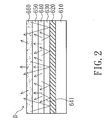
- FIG. 2 is a schematic cross-sectional view of an element integrated by the wavelength conversion element and the first excitation light source in accordance with an embodiment of the invention.
- the element includes a conductive carrier 610, a reflective layer 620, a hole-transmission layer 630, a light-emitting layer 640, an electron transmission layer 650 and a wavelength conversion layer 660.
- the layers are sequentially stacked, wherein the positions of the hole-transmission layer 630 and the electron transmission layer 650 are interchangeable.
- the electrical holes and electrons respectively provided by the hole-transmission layer 630 and the electron transmission layer 650 are combined in the light-emitting layer 640 to generate photons, and accordingly the light 641 is formed and emitted out from the light-emitting layer 640.
- a portion of the light 641 from the light emitting layer 640 transmitting toward the reflective layer 620 is reflected to the wavelength conversion layer 660, and the portion of light 641 emitting toward the wavelength conversion layer 660 is defined as the first excitation beam C1.
- the wavelength conversion layer 660 then converts the first excitation beam C1 into the wavelength conversion beam D and a portion of the wavelength conversion beam D transmitting toward the reflective layer 620 is reflected and then emitted out the element through the wavelength conversion layer 660.
- FIG. 3 is a schematic view of an illumination system in accordance with another embodiment of the invention.
- the illumination system 10a of the embodiment is similar to the illumination system 10 of FIG. 1 , and only the difference between the two is described in the following.
- the first excitation light source 110 and the second excitation light source 120 of the light source assembly 100a are disposed on the same side of the dichroic element 130a.
- the second excitation beam C2 may be reflected by the dichroic element 130a and the wavelength conversion beam D may pass through the dichroic element 130a.
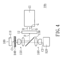
- FIG. 4 is a schematic view of an illumination system in accordance with another embodiment of the invention.
- the illumination system 10b of the embodiment is similar to the illumination system 10 of FIG. 1 , and only the difference between the two is described in the following.
- the illumination system 10b of the embodiment further includes a color wheel 12.
- the color wheel 12 is disposed on the transmission path of the wavelength conversion beam D reflected by the dichroic element 130.
- the first excitation beam C1 and the second excitation beam C2 respectively provided by the first excitation light source 110 and the second excitation light source 120 are ultraviolet light
- the wavelength conversion beam D emitted from the wavelength conversion element 140 is white light.
- the wavelength conversion beam D may be sequentially filtered into beams with various colors, such as red beam R, green beam G and blue beam B, which are transmitted to the light integral rod 11 in timing. It is to be noted that the colors of the beams filtered by the color wheel 12 and the generating sequence of the beams with various colors are not limited in the invention.
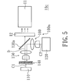
- FIG. 5 is a schematic view of an illumination system in accordance with another embodiment of the invention.
- the illumination system 10c of the embodiment is similar to the illumination system 10b of FIG. 4 , and only the difference between the two is described in the following.
- the first excitation light source 110 and the second excitation light source 120 of the light source assembly 100a are disposed on the same side of the dichroic element 130a.
- the second excitation beam C2 may be reflected by the dichroic element 130a; and the wavelength conversion beam D may pass through the dichroic element 130a and then is transmitted to the color wheel 12.
- FIG. 6 is a schematic view of an illumination system in accordance with another embodiment of the invention.
- the illumination system 10d of the embodiment is similar to the illumination system 10b of FIG. 4 , and only the difference between the two is described in the following.
- the first excitation beam C1 and the second excitation beam C2 respectively provided by the first excitation light source 110 and the second excitation light source 120 are blue light
- the wavelength conversion beam D emitted from the wavelength conversion element 140 is yellow light.
- the illumination system 10d further includes a blue light source assembly 13.
- the blue light source assembly 13 and the second excitation light source 120 are disposed on the same side of the dichroic element 130.
- the blue light source assembly 13 is configured to provide a blue beam B1.
- the blue beam B1 passes through the dichroic element 130 and is combined with wavelength conversion beam D to form a white beam W.
- the white beam W is then transmitted to the color wheel 12.
- the blue light source assembly 13 includes a blue light source 13a and a collimating element 13b.
- the blue light source 13a may be a blue light emitting diode, a laser light source, or other suitable light source.
- the collimating element 13b may have a structure same as those of the first collimating element 150 and the second collimating element 160, for example.
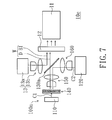
- FIG. 7 is a schematic view of an illumination system in accordance with another embodiment of the invention.
- the illumination system 10e of the embodiment is similar to the illumination system 10d of FIG. 6 , and only the difference between the two is described in the following.
- the first excitation light source 110 and the second excitation light source 120 of the light source assembly 100a are disposed on the same side of the dichroic element 130a.
- the second excitation beam C2 may be reflected by the dichroic element 130a; and the wavelength conversion beam D may pass through the dichroic element 130a and then is transmitted to the color wheel 12.
- the blue light source assembly 13 and the second excitation light source 120 are disposed on the two sides of the dichroic element 130a.
- the blue light source assembly 13 is configured to provide the blue beam B1 to the dichroic element 130a.
- the blue beam B1 may be reflected by the dichroic element 130 and then combined with the wavelength conversion beam D to form a white beam W.
- the white beam W is then transmitted to the color wheel 12.
- Each one of the illumination systems 10 ⁇ 10e of the above embodiments has one light source assembly 100 or 100a.
- the illumination system may include more than one light source assembly having a structure same as that of the light source assembly 100 or 100a.
- FIG. 8 is a schematic view of an illumination system in accordance with another embodiment of the invention.
- the illumination system 20 of the embodiment includes a first light source assembly 200 configured to provided a first color beam L1, a second light source assembly 300 configured to provided a second color beam L2, and a third light source assembly 400 configured to provided a third color beam L3; wherein the first color beam L1, the second color beam L2 and the third color beam L3 may be integrated as an illumination beam L4.
- the first light source assembly 200 includes a first excitation light source 210, a second excitation light source 220, a first dichroic element 230 and a first wavelength conversion element 240.
- the first excitation light source 210 is configured to provide a first excitation beam C1; the second excitation light source 220 is configured to provide a second excitation beam C2; and the first excitation beam C1 and the second excitation beam C2 have the same color.
- the first dichroic element 230 is disposed between the first excitation light source 210 and the second excitation light source 220.
- the second excitation beam C2 is transmitted toward the first excitation light source 210 via the first dichroic element 230.
- the first wavelength conversion element 240 is disposed between the first excitation light source 210 and the first dichroic element 230.
- the first wavelength conversion element 240 is configured to convert the first excitation beam C 1 and the second excitation beam C2 into a first wavelength conversion beam and transmit the first wavelength conversion beam toward the first dichroic element 230; wherein the first wavelength conversion beam is defined as the aforementioned first color beam L1.
- the second light source assembly 300 includes a third excitation light source 310, a fourth excitation light source 320, a second dichroic element 330 and a second wavelength conversion element 340.
- the third excitation light source 310 is configured to provide a third excitation beam C3;
- the fourth excitation light source 320 is configured to provide a fourth excitation beam C4; and
- the third excitation beam C3 and the fourth excitation beam C4 have the same color.
- the second dichroic element 330 is disposed between the third excitation light source 310 and the fourth excitation light source 320.
- the fourth excitation beam C4 is transmitted toward the third excitation light source 310 via the second dichroic element 330.
- the second wavelength conversion element 340 is disposed between the third excitation light source 310 and the second dichroic element 330.
- the second wavelength conversion element 340 is configured to convert the third excitation beam C3 and the fourth excitation beam C4 into a second wavelength conversion beam and transmit the second wavelength conversion beam toward the second dichroic element 330; wherein the second wavelength conversion beam is defined as the aforementioned second color beam L2.
- the third light source assembly 400 includes a light source 410 configured to provide the third color beam L3.
- the light source 410 may be a light emitting diode, a laser light source, or other suitable light source.
- the third light source assembly 400 may further include a collimating element 420, which is disposed on the transmission path of the third color beam L3.
- the first light source assembly 200 and the second light source assembly 300 have a configuration similar to that of the light source assembly 100.
- the first wavelength conversion element 240 and the second wavelength conversion element 340 have a structure same as that of the wavelength conversion element 140.
- the first wavelength conversion element 240 and the second wavelength conversion element 340 may cover the first excitation light source 210 and the third excitation light source 310, respectively.
- the first wavelength conversion element and the first excitation light source may be integrated as an element similar to that shown in FIG. 2 ; and the second wavelength conversion element and the third excitation light source may be integrated as an element similar to that shown in FIG. 2 .
- first excitation light source 210, the second excitation light source 220, the third excitation light source 310 and the fourth excitation light source 320 each may be a light emitting diode, a laser light source, or other suitable light source.
- first light source assembly 200 may further include a first collimating element 250, which is disposed between the first wavelength conversion element 240 and the first dichroic element 230, and a second collimating element 260, which is disposed between the second wavelength conversion element 220 and the first dichroic element 230.
- the second light source assembly 300 may further include a third collimating element 350, which is disposed between the second wavelength conversion element 340 and the second dichroic element 330, and a fourth collimating element 360, which is disposed between the fourth wavelength conversion element 320 and the second dichroic element 330.
- the second dichroic element 330 is disposed between the first dichroic element 230 and the third light source assembly 400; and the third color beam L3 sequentially passes through the second dichroic element 330 and the first dichroic element 230.
- the third excitation light source 310 and the fourth excitation light source 320 are disposed on the two sides of the second dichroic element 330, respectively.
- the fourth excitation beam C4 may pass through the second dichroic element 330; the second color beam L2 may be reflected to the first dichroic element 230 by the second dichroic element 330; and the second color beam L2 may pass through the first dichroic element 230.
- the first excitation light source 210 and the second excitation light source 220 are disposed on the two sides of the first dichroic element 230, respectively.
- the second excitation beam C2 may pass through the first dichroic element 230; the first color beam L1 may be reflected by the first dichroic element 230, so that the first color beam L1, the second color beam L2 and the third color beam L3 are integrated as the illumination beam L4.
- the first excitation beam C1, the second excitation beam C2, the third excitation beam C3 and the fourth excitation beam C4 are blue light; but the invention is not limited thereto.
- the first color beam L1 is green light
- the second color beam L2 is red light
- the third color beam L3 is blue light; but the invention is not limited thereto.
- the colors of the first color beam L1 and the second color beam L2 are interchangeable.
- the first light source assembly 200, the second light source assembly 300 and the third light source assembly 400 may be configured to simultaneously emit light or not emit light simultaneously.
- the first light source assembly 200, the second light source assembly 300 and the third light source assembly 400 may sequentially provide the first color beam L1, the second color beam L2 and the third color beam L3 in timing, respectively; and accordingly, the illumination beam L4 at each time point includes only one of the first color beam L1, the second color beam L2 and the third color beam L3.
- the first light source assembly 200, the second light source assembly 300 and the third light source assembly 400 may simultaneously provide the first color beam L1, the second color beam L2 and the third color beam L3, respectively; and accordingly, the illumination beam L4 at each time point is form by a mix of the first color beam L1, the second color beam L2 and the third color beam L3.
- the illumination system 20 of the embodiment may further include other optical element(s), which is disposed on the transmission path of the illumination beam L4.
- the optical element may include a light equalizing element (e.g., light integral rod or lens array), a lens or a mirror, and the quantity of the aforementioned optical element may be one or more than one.
- FIG. 8 is exemplified by having a light integral rod 21.
- the illumination system 20a of the embodiment further includes at least one lens 25, which is disposed between the first dichroic element 230 and the second dichroic element 330.
- FIG. 9 is exemplified by having two lenses 25, the quantity of the lens 25 or other optical element is not limited in the invention.
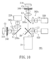
- FIG. 10 is a schematic view of an illumination system in accordance with another embodiment of the invention.
- the illumination system 20b of the embodiment is similar to the illumination system 20 of FIG. 8 , and only the difference between the two is described in the following.
- the illumination system 20b of the embodiment further includes a beam combiner 26, which is disposed among the first light source assembly 200a, the second light source assembly 300a and the third light source assembly 400.
- the first light source assembly 200a and the third light source assembly 400 are disposed on the two opposite sides of the beam combiner 26, respectively.
- the first color beam L1 and the third color beam L3 may be reflected by the beam combiner 26; the second color beam L2 may pass through the beam combiner 26; and so that the first color beam L1, the second color beam L2 and the third color beam L3 may be integrated as the illumination beam L4.
- the beam combiner 26 may be an X beam combiner plate or an X beam combiner prism.
- the first light source assembly 200a and the second light source assembly 300a are similar to the light source assembly 100a in FIG. 3 . That is, in the first light source assembly 200a, the first excitation light source 210 and the second excitation light source 220 are disposed on the same side of the first dichroic element 230a.
- the second excitation beam C2 may be reflected by the first dichroic element 230a; and the first color beam L1 may pass through the first dichroic element 230a and then is transmitted to the beam combiner 26.
- the third excitation light source 310 and the fourth excitation light source 320 are disposed on the same side of the second dichroic element 330a.
- the fourth excitation beam C4 may be reflected by the second dichroic element 330a; and the second color beam L2 may pass through the second dichroic element 330a and then is transmitted to the beam combiner 26.
- FIG. 11 is a schematic view of a projection apparatus in accordance with an embodiment of the invention.
- the projection apparatus 500 of the embodiment includes the illumination system 10 of FIG. 1 , a light valve 170 and a projection lens 180.
- the wavelength conversion beam D provided by the illumination system 10 is transmitted to the light equalizing element 11 (e.g., a light integral rod or a lens array)
- the wavelength conversion beam D first is equalized by the light equalizing element 11 and then is emitted on the light valve 170 uniformly.
- the light valve 170 may be a digital micromirror device (DMD), a liquid crystal on silicon panel (LCoS) or other suitable component.
- the light valve 170 is configured to convert the wavelength conversion beam D into an image beam M.
- the image beam M is then projected into a screen (not shown) through the projection lens 180.
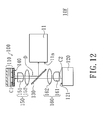
- FIG. 12 is a schematic view of an illumination system in accordance with another embodiment of the invention.
- the illumination system 10F includes a light source assembly 100.
- the light source assembly 100 includes a first excitation light source 110, a second excitation light source 120, a dichroic element 130, a wavelength conversion element 140, a first collimating element 150 and a second collimating element 160.
- the disposition of the first excitation light source 110 and the wavelength conversion element 140 of the embodiment of the invention is as well as the light source assembly of FIG. 2 .
- the first light excitation light source 110 and the wavelength conversion element 140 are packaged together by the transparent resin or other transparent material (not shown).
- This embodiment is the wavelength conversion element 140 disposed between the first excitation light source 110 and the dichroic element 130.
- the wavelength conversion element 140 may be attached the first excitation light source 110, and then adds a transparent protective layer above so as to protect the wavelength conversion element (not shown).
- the first excitation light source 110 is configured to provide a first excitation beam C1.
- the second excitation light source 120 is configured to provide a second excitation beam C2, and the first excitation beam C1 and the second excitation beam C2 have the same color, such as blue, for example.
- the wavelengths of the first excitation beam C 1 and the second excitation beam C2 may be located within a certain range.
- the wavelengths of the first excitation beam C 1 and the second excitation beam C2 may be located within in a range 450 ⁇ 475 nm if the two beams are blue.
- the dichroic element 130 is disposed between the first excitation light source 110 and the second excitation light source 120.
- the dichroic element 130 is a dichroic mirror, through which the second excitation beam C2 is transmitted toward the first excitation light source 110.
- the wavelength conversion element 140 is disposed between the first excitation light source 110 and the dichroic element 130.
- the wavelength conversion element 140 is configured to convert the first excitation beam C1 and the second excitation beam C2 into a wavelength conversion beam D and transmit the wavelength conversion beam D toward the dichroic element 130.
- the first collimating element 150 is disposed between the wavelength conversion element 140 and the dichroic element 130.
- the second collimating element 160 is disposed between the second excitation light source 120 and the dichroic element 130.
- the light source assembly has two excitation light sources for providing excitation beams and the two excitation beams excite the wavelength conversion element to emit the wavelength conversion through the two sides of the wavelength conversion element, respectively. Therefore, the optical power of the wavelength conversion beam may be enhanced without increasing the light etendue, and consequentially the illumination system has enhanced optical power of the beam provided by the illumination system.
Landscapes
- Physics & Mathematics (AREA)
- General Physics & Mathematics (AREA)
- Engineering & Computer Science (AREA)
- Multimedia (AREA)
- Optics & Photonics (AREA)
- Projection Apparatus (AREA)
Priority Applications (1)
| Application Number | Priority Date | Filing Date | Title |
|---|---|---|---|
| EP16192627.4A EP3306392B1 (fr) | 2016-10-06 | 2016-10-06 | Système d'éclairage et appareil de projection |
Applications Claiming Priority (1)
| Application Number | Priority Date | Filing Date | Title |
|---|---|---|---|
| EP16192627.4A EP3306392B1 (fr) | 2016-10-06 | 2016-10-06 | Système d'éclairage et appareil de projection |
Publications (2)
| Publication Number | Publication Date |
|---|---|
| EP3306392A1 true EP3306392A1 (fr) | 2018-04-11 |
| EP3306392B1 EP3306392B1 (fr) | 2021-05-05 |
Family
ID=57211263
Family Applications (1)
| Application Number | Title | Priority Date | Filing Date |
|---|---|---|---|
| EP16192627.4A Active EP3306392B1 (fr) | 2016-10-06 | 2016-10-06 | Système d'éclairage et appareil de projection |
Country Status (1)
| Country | Link |
|---|---|
| EP (1) | EP3306392B1 (fr) |
Cited By (2)
| Publication number | Priority date | Publication date | Assignee | Title |
|---|---|---|---|---|
| CN111413841A (zh) * | 2019-01-04 | 2020-07-14 | 深圳光峰科技股份有限公司 | 波长转换装置、光源系统与显示设备 |
| US11537037B2 (en) * | 2020-11-27 | 2022-12-27 | Ricoh Company, Ltd. | Light source device, image projection apparatus, and light source optical system |
Citations (7)
| Publication number | Priority date | Publication date | Assignee | Title |
|---|---|---|---|---|
| EP1605199A2 (fr) * | 2004-06-04 | 2005-12-14 | LumiLeds Lighting U.S., LLC | Conversion de longueur d'onde à commande à distance pour dispositif d'illumination |
| WO2009017992A1 (fr) * | 2007-07-30 | 2009-02-05 | Ylx Corp. | Dispositif d'éclairage multicolore utilisant une plaque mobile ayant des matériaux de conversion de longueur d'onde |
| US20120099082A1 (en) * | 2010-10-21 | 2012-04-26 | Coretronic Corporation | Illumination apparatus and projection apparatus |
| DE102010062465A1 (de) * | 2010-12-06 | 2012-06-06 | Osram Ag | Leuchtvorrichtung |
| US20130163224A1 (en) * | 2011-12-27 | 2013-06-27 | Delta Electronics, Inc. | Illumination system and wavelength-transforming device thereof |
| US20140347842A1 (en) * | 2011-10-07 | 2014-11-27 | Cymtec Ltd | Radiation generating apparatus and a method of generating radiation |
| US20150146409A1 (en) * | 2012-07-09 | 2015-05-28 | Olympus Corporation | Light source apparatus |
-
2016
- 2016-10-06 EP EP16192627.4A patent/EP3306392B1/fr active Active
Patent Citations (7)
| Publication number | Priority date | Publication date | Assignee | Title |
|---|---|---|---|---|
| EP1605199A2 (fr) * | 2004-06-04 | 2005-12-14 | LumiLeds Lighting U.S., LLC | Conversion de longueur d'onde à commande à distance pour dispositif d'illumination |
| WO2009017992A1 (fr) * | 2007-07-30 | 2009-02-05 | Ylx Corp. | Dispositif d'éclairage multicolore utilisant une plaque mobile ayant des matériaux de conversion de longueur d'onde |
| US20120099082A1 (en) * | 2010-10-21 | 2012-04-26 | Coretronic Corporation | Illumination apparatus and projection apparatus |
| DE102010062465A1 (de) * | 2010-12-06 | 2012-06-06 | Osram Ag | Leuchtvorrichtung |
| US20140347842A1 (en) * | 2011-10-07 | 2014-11-27 | Cymtec Ltd | Radiation generating apparatus and a method of generating radiation |
| US20130163224A1 (en) * | 2011-12-27 | 2013-06-27 | Delta Electronics, Inc. | Illumination system and wavelength-transforming device thereof |
| US20150146409A1 (en) * | 2012-07-09 | 2015-05-28 | Olympus Corporation | Light source apparatus |
Cited By (3)
| Publication number | Priority date | Publication date | Assignee | Title |
|---|---|---|---|---|
| CN111413841A (zh) * | 2019-01-04 | 2020-07-14 | 深圳光峰科技股份有限公司 | 波长转换装置、光源系统与显示设备 |
| CN111413841B (zh) * | 2019-01-04 | 2023-08-11 | 深圳光峰科技股份有限公司 | 波长转换装置、光源系统与显示设备 |
| US11537037B2 (en) * | 2020-11-27 | 2022-12-27 | Ricoh Company, Ltd. | Light source device, image projection apparatus, and light source optical system |
Also Published As
| Publication number | Publication date |
|---|---|
| EP3306392B1 (fr) | 2021-05-05 |
Similar Documents
| Publication | Publication Date | Title |
|---|---|---|
| US10101644B2 (en) | Illumination system and projection apparatus | |
| US9341933B2 (en) | Wavelength conversion and filtering module and light source system | |
| US10379431B2 (en) | Projection apparatus and illumination system having wavelength conversion modules | |
| US9977317B2 (en) | Illumination system and projection device | |
| US9033518B2 (en) | Illumination system comprising a rotation wheel with transmissive and reflective regions and a phosphor used for converting a light beam of a first color from the reflective or transmissive region to a second color and projection apparatus | |
| US9152031B2 (en) | Light source module and projection apparatus | |
| CN105278226B (zh) | 光源模块与投影装置 | |
| US9348204B2 (en) | Light source module with wavelength conversion module and projection apparatus | |
| US10331022B2 (en) | Light source module and projection apparatus | |
| US10613318B2 (en) | Bi-directional excitation color wheel and light source system thereof | |
| US20130321777A1 (en) | Illumination system and projection apparatus | |
| US9977316B2 (en) | Projection apparatus and illumination system thereof | |
| US10558114B2 (en) | Illumination system and projection apparatus having a small volume | |
| US11163227B2 (en) | Illumination system, wavelength conversion module, projection apparatus and illumination control method | |
| KR102361693B1 (ko) | 조명 시스템 | |
| US20190253676A1 (en) | Illumination system and projection apparatus | |
| EP2574967A1 (fr) | Dispositif de génération d'images avec efficacité d'éclairage améliorée | |
| US11531258B2 (en) | Light source module and projection device | |
| TWI656361B (zh) | 照明系統與投影裝置 | |
| EP3306392B1 (fr) | Système d'éclairage et appareil de projection | |
| EP4318126B1 (fr) | Système d'éclairage et dispositif de projection | |
| JP7238367B2 (ja) | 光源装置および電子機器 | |
| US11841612B2 (en) | Illumination system and projection device | |
| EP3136721B1 (fr) | Système de production d'un faisceau lumineux de sortie d'un spectre donné | |
| KR102186825B1 (ko) | 광원장치 및 이를 포함하는 영상투사장치 |
Legal Events
| Date | Code | Title | Description |
|---|---|---|---|
| PUAI | Public reference made under article 153(3) epc to a published international application that has entered the european phase |
Free format text: ORIGINAL CODE: 0009012 |
|
| STAA | Information on the status of an ep patent application or granted ep patent |
Free format text: STATUS: THE APPLICATION HAS BEEN PUBLISHED |
|
| AK | Designated contracting states |
Kind code of ref document: A1 Designated state(s): AL AT BE BG CH CY CZ DE DK EE ES FI FR GB GR HR HU IE IS IT LI LT LU LV MC MK MT NL NO PL PT RO RS SE SI SK SM TR |
|
| AX | Request for extension of the european patent |
Extension state: BA ME |
|
| STAA | Information on the status of an ep patent application or granted ep patent |
Free format text: STATUS: REQUEST FOR EXAMINATION WAS MADE |
|
| 17P | Request for examination filed |
Effective date: 20181004 |
|
| RBV | Designated contracting states (corrected) |
Designated state(s): AL AT BE BG CH CY CZ DE DK EE ES FI FR GB GR HR HU IE IS IT LI LT LU LV MC MK MT NL NO PL PT RO RS SE SI SK SM TR |
|
| STAA | Information on the status of an ep patent application or granted ep patent |
Free format text: STATUS: EXAMINATION IS IN PROGRESS |
|
| 17Q | First examination report despatched |
Effective date: 20190802 |
|
| GRAP | Despatch of communication of intention to grant a patent |
Free format text: ORIGINAL CODE: EPIDOSNIGR1 |
|
| STAA | Information on the status of an ep patent application or granted ep patent |
Free format text: STATUS: GRANT OF PATENT IS INTENDED |
|
| INTG | Intention to grant announced |
Effective date: 20201216 |
|
| GRAS | Grant fee paid |
Free format text: ORIGINAL CODE: EPIDOSNIGR3 |
|
| GRAA | (expected) grant |
Free format text: ORIGINAL CODE: 0009210 |
|
| STAA | Information on the status of an ep patent application or granted ep patent |
Free format text: STATUS: THE PATENT HAS BEEN GRANTED |
|
| AK | Designated contracting states |
Kind code of ref document: B1 Designated state(s): AL AT BE BG CH CY CZ DE DK EE ES FI FR GB GR HR HU IE IS IT LI LT LU LV MC MK MT NL NO PL PT RO RS SE SI SK SM TR |
|
| REG | Reference to a national code |
Ref country code: GB Ref legal event code: FG4D |
|
| REG | Reference to a national code |
Ref country code: CH Ref legal event code: EP |
|
| REG | Reference to a national code |
Ref country code: AT Ref legal event code: REF Ref document number: 1390545 Country of ref document: AT Kind code of ref document: T Effective date: 20210515 |
|
| REG | Reference to a national code |
Ref country code: IE Ref legal event code: FG4D |
|
| REG | Reference to a national code |
Ref country code: DE Ref legal event code: R096 Ref document number: 602016057265 Country of ref document: DE |
|
| REG | Reference to a national code |
Ref country code: LT Ref legal event code: MG9D |
|
| REG | Reference to a national code |
Ref country code: AT Ref legal event code: MK05 Ref document number: 1390545 Country of ref document: AT Kind code of ref document: T Effective date: 20210505 |
|
| PG25 | Lapsed in a contracting state [announced via postgrant information from national office to epo] |
Ref country code: AT Free format text: LAPSE BECAUSE OF FAILURE TO SUBMIT A TRANSLATION OF THE DESCRIPTION OR TO PAY THE FEE WITHIN THE PRESCRIBED TIME-LIMIT Effective date: 20210505 Ref country code: BG Free format text: LAPSE BECAUSE OF FAILURE TO SUBMIT A TRANSLATION OF THE DESCRIPTION OR TO PAY THE FEE WITHIN THE PRESCRIBED TIME-LIMIT Effective date: 20210805 Ref country code: HR Free format text: LAPSE BECAUSE OF FAILURE TO SUBMIT A TRANSLATION OF THE DESCRIPTION OR TO PAY THE FEE WITHIN THE PRESCRIBED TIME-LIMIT Effective date: 20210505 Ref country code: FI Free format text: LAPSE BECAUSE OF FAILURE TO SUBMIT A TRANSLATION OF THE DESCRIPTION OR TO PAY THE FEE WITHIN THE PRESCRIBED TIME-LIMIT Effective date: 20210505 Ref country code: LT Free format text: LAPSE BECAUSE OF FAILURE TO SUBMIT A TRANSLATION OF THE DESCRIPTION OR TO PAY THE FEE WITHIN THE PRESCRIBED TIME-LIMIT Effective date: 20210505 |
|
| PG25 | Lapsed in a contracting state [announced via postgrant information from national office to epo] |
Ref country code: IS Free format text: LAPSE BECAUSE OF FAILURE TO SUBMIT A TRANSLATION OF THE DESCRIPTION OR TO PAY THE FEE WITHIN THE PRESCRIBED TIME-LIMIT Effective date: 20210905 Ref country code: GR Free format text: LAPSE BECAUSE OF FAILURE TO SUBMIT A TRANSLATION OF THE DESCRIPTION OR TO PAY THE FEE WITHIN THE PRESCRIBED TIME-LIMIT Effective date: 20210806 Ref country code: LV Free format text: LAPSE BECAUSE OF FAILURE TO SUBMIT A TRANSLATION OF THE DESCRIPTION OR TO PAY THE FEE WITHIN THE PRESCRIBED TIME-LIMIT Effective date: 20210505 Ref country code: SE Free format text: LAPSE BECAUSE OF FAILURE TO SUBMIT A TRANSLATION OF THE DESCRIPTION OR TO PAY THE FEE WITHIN THE PRESCRIBED TIME-LIMIT Effective date: 20210505 Ref country code: RS Free format text: LAPSE BECAUSE OF FAILURE TO SUBMIT A TRANSLATION OF THE DESCRIPTION OR TO PAY THE FEE WITHIN THE PRESCRIBED TIME-LIMIT Effective date: 20210505 Ref country code: NO Free format text: LAPSE BECAUSE OF FAILURE TO SUBMIT A TRANSLATION OF THE DESCRIPTION OR TO PAY THE FEE WITHIN THE PRESCRIBED TIME-LIMIT Effective date: 20210805 Ref country code: PL Free format text: LAPSE BECAUSE OF FAILURE TO SUBMIT A TRANSLATION OF THE DESCRIPTION OR TO PAY THE FEE WITHIN THE PRESCRIBED TIME-LIMIT Effective date: 20210505 Ref country code: PT Free format text: LAPSE BECAUSE OF FAILURE TO SUBMIT A TRANSLATION OF THE DESCRIPTION OR TO PAY THE FEE WITHIN THE PRESCRIBED TIME-LIMIT Effective date: 20210906 |
|
| REG | Reference to a national code |
Ref country code: NL Ref legal event code: MP Effective date: 20210505 |
|
| PG25 | Lapsed in a contracting state [announced via postgrant information from national office to epo] |
Ref country code: NL Free format text: LAPSE BECAUSE OF FAILURE TO SUBMIT A TRANSLATION OF THE DESCRIPTION OR TO PAY THE FEE WITHIN THE PRESCRIBED TIME-LIMIT Effective date: 20210505 |
|
| PG25 | Lapsed in a contracting state [announced via postgrant information from national office to epo] |
Ref country code: CZ Free format text: LAPSE BECAUSE OF FAILURE TO SUBMIT A TRANSLATION OF THE DESCRIPTION OR TO PAY THE FEE WITHIN THE PRESCRIBED TIME-LIMIT Effective date: 20210505 Ref country code: DK Free format text: LAPSE BECAUSE OF FAILURE TO SUBMIT A TRANSLATION OF THE DESCRIPTION OR TO PAY THE FEE WITHIN THE PRESCRIBED TIME-LIMIT Effective date: 20210505 Ref country code: EE Free format text: LAPSE BECAUSE OF FAILURE TO SUBMIT A TRANSLATION OF THE DESCRIPTION OR TO PAY THE FEE WITHIN THE PRESCRIBED TIME-LIMIT Effective date: 20210505 Ref country code: SM Free format text: LAPSE BECAUSE OF FAILURE TO SUBMIT A TRANSLATION OF THE DESCRIPTION OR TO PAY THE FEE WITHIN THE PRESCRIBED TIME-LIMIT Effective date: 20210505 Ref country code: SK Free format text: LAPSE BECAUSE OF FAILURE TO SUBMIT A TRANSLATION OF THE DESCRIPTION OR TO PAY THE FEE WITHIN THE PRESCRIBED TIME-LIMIT Effective date: 20210505 Ref country code: RO Free format text: LAPSE BECAUSE OF FAILURE TO SUBMIT A TRANSLATION OF THE DESCRIPTION OR TO PAY THE FEE WITHIN THE PRESCRIBED TIME-LIMIT Effective date: 20210505 Ref country code: ES Free format text: LAPSE BECAUSE OF FAILURE TO SUBMIT A TRANSLATION OF THE DESCRIPTION OR TO PAY THE FEE WITHIN THE PRESCRIBED TIME-LIMIT Effective date: 20210505 |
|
| REG | Reference to a national code |
Ref country code: DE Ref legal event code: R097 Ref document number: 602016057265 Country of ref document: DE |
|
| PLBE | No opposition filed within time limit |
Free format text: ORIGINAL CODE: 0009261 |
|
| STAA | Information on the status of an ep patent application or granted ep patent |
Free format text: STATUS: NO OPPOSITION FILED WITHIN TIME LIMIT |
|
| 26N | No opposition filed |
Effective date: 20220208 |
|
| PG25 | Lapsed in a contracting state [announced via postgrant information from national office to epo] |
Ref country code: IS Free format text: LAPSE BECAUSE OF FAILURE TO SUBMIT A TRANSLATION OF THE DESCRIPTION OR TO PAY THE FEE WITHIN THE PRESCRIBED TIME-LIMIT Effective date: 20210905 Ref country code: AL Free format text: LAPSE BECAUSE OF FAILURE TO SUBMIT A TRANSLATION OF THE DESCRIPTION OR TO PAY THE FEE WITHIN THE PRESCRIBED TIME-LIMIT Effective date: 20210505 |
|
| REG | Reference to a national code |
Ref country code: CH Ref legal event code: PL |
|
| REG | Reference to a national code |
Ref country code: BE Ref legal event code: MM Effective date: 20211031 |
|
| PG25 | Lapsed in a contracting state [announced via postgrant information from national office to epo] |
Ref country code: MC Free format text: LAPSE BECAUSE OF FAILURE TO SUBMIT A TRANSLATION OF THE DESCRIPTION OR TO PAY THE FEE WITHIN THE PRESCRIBED TIME-LIMIT Effective date: 20210505 |
|
| PG25 | Lapsed in a contracting state [announced via postgrant information from national office to epo] |
Ref country code: LU Free format text: LAPSE BECAUSE OF NON-PAYMENT OF DUE FEES Effective date: 20211006 Ref country code: IT Free format text: LAPSE BECAUSE OF FAILURE TO SUBMIT A TRANSLATION OF THE DESCRIPTION OR TO PAY THE FEE WITHIN THE PRESCRIBED TIME-LIMIT Effective date: 20210505 Ref country code: BE Free format text: LAPSE BECAUSE OF NON-PAYMENT OF DUE FEES Effective date: 20211031 |
|
| PG25 | Lapsed in a contracting state [announced via postgrant information from national office to epo] |
Ref country code: LI Free format text: LAPSE BECAUSE OF NON-PAYMENT OF DUE FEES Effective date: 20211031 Ref country code: CH Free format text: LAPSE BECAUSE OF NON-PAYMENT OF DUE FEES Effective date: 20211031 |
|
| PG25 | Lapsed in a contracting state [announced via postgrant information from national office to epo] |
Ref country code: IE Free format text: LAPSE BECAUSE OF NON-PAYMENT OF DUE FEES Effective date: 20211006 |
|
| PG25 | Lapsed in a contracting state [announced via postgrant information from national office to epo] |
Ref country code: HU Free format text: LAPSE BECAUSE OF FAILURE TO SUBMIT A TRANSLATION OF THE DESCRIPTION OR TO PAY THE FEE WITHIN THE PRESCRIBED TIME-LIMIT; INVALID AB INITIO Effective date: 20161006 |
|
| PG25 | Lapsed in a contracting state [announced via postgrant information from national office to epo] |
Ref country code: CY Free format text: LAPSE BECAUSE OF FAILURE TO SUBMIT A TRANSLATION OF THE DESCRIPTION OR TO PAY THE FEE WITHIN THE PRESCRIBED TIME-LIMIT Effective date: 20210505 |
|
| PG25 | Lapsed in a contracting state [announced via postgrant information from national office to epo] |
Ref country code: MK Free format text: LAPSE BECAUSE OF FAILURE TO SUBMIT A TRANSLATION OF THE DESCRIPTION OR TO PAY THE FEE WITHIN THE PRESCRIBED TIME-LIMIT Effective date: 20210505 |
|
| PG25 | Lapsed in a contracting state [announced via postgrant information from national office to epo] |
Ref country code: MT Free format text: LAPSE BECAUSE OF FAILURE TO SUBMIT A TRANSLATION OF THE DESCRIPTION OR TO PAY THE FEE WITHIN THE PRESCRIBED TIME-LIMIT Effective date: 20210505 |
|
| PG25 | Lapsed in a contracting state [announced via postgrant information from national office to epo] |
Ref country code: TR Free format text: LAPSE BECAUSE OF FAILURE TO SUBMIT A TRANSLATION OF THE DESCRIPTION OR TO PAY THE FEE WITHIN THE PRESCRIBED TIME-LIMIT Effective date: 20210505 |
|
| PGFP | Annual fee paid to national office [announced via postgrant information from national office to epo] |
Ref country code: DE Payment date: 20251028 Year of fee payment: 10 |
|
| PGFP | Annual fee paid to national office [announced via postgrant information from national office to epo] |
Ref country code: GB Payment date: 20251024 Year of fee payment: 10 |
|
| PGFP | Annual fee paid to national office [announced via postgrant information from national office to epo] |
Ref country code: FR Payment date: 20251029 Year of fee payment: 10 |