EP3306431B1 - Computerimplementiertes verfahren und system zum führen eines fahrzeugs in einem szenario mit hindernissen - Google Patents
Computerimplementiertes verfahren und system zum führen eines fahrzeugs in einem szenario mit hindernissen Download PDFInfo
- Publication number
- EP3306431B1 EP3306431B1 EP16382458.4A EP16382458A EP3306431B1 EP 3306431 B1 EP3306431 B1 EP 3306431B1 EP 16382458 A EP16382458 A EP 16382458A EP 3306431 B1 EP3306431 B1 EP 3306431B1
- Authority
- EP
- European Patent Office
- Prior art keywords
- waypoint
- obstacle
- target
- distance
- source
- Prior art date
- Legal status (The legal status is an assumption and is not a legal conclusion. Google has not performed a legal analysis and makes no representation as to the accuracy of the status listed.)
- Active
Links
Images



Classifications
-
- G—PHYSICS
- G01—MEASURING; TESTING
- G01C—MEASURING DISTANCES, LEVELS OR BEARINGS; SURVEYING; NAVIGATION; GYROSCOPIC INSTRUMENTS; PHOTOGRAMMETRY OR VIDEOGRAMMETRY
- G01C21/00—Navigation; Navigational instruments not provided for in groups G01C1/00 - G01C19/00
- G01C21/26—Navigation; Navigational instruments not provided for in groups G01C1/00 - G01C19/00 specially adapted for navigation in a road network
- G01C21/34—Route searching; Route guidance
- G01C21/3407—Route searching; Route guidance specially adapted for specific applications
- G01C21/3415—Dynamic re-routing, e.g. recalculating the route when the user deviates from calculated route or after detecting real-time traffic data or accidents
-
- G—PHYSICS
- G01—MEASURING; TESTING
- G01C—MEASURING DISTANCES, LEVELS OR BEARINGS; SURVEYING; NAVIGATION; GYROSCOPIC INSTRUMENTS; PHOTOGRAMMETRY OR VIDEOGRAMMETRY
- G01C21/00—Navigation; Navigational instruments not provided for in groups G01C1/00 - G01C19/00
- G01C21/20—Instruments for performing navigational calculations
-
- G—PHYSICS
- G01—MEASURING; TESTING
- G01C—MEASURING DISTANCES, LEVELS OR BEARINGS; SURVEYING; NAVIGATION; GYROSCOPIC INSTRUMENTS; PHOTOGRAMMETRY OR VIDEOGRAMMETRY
- G01C21/00—Navigation; Navigational instruments not provided for in groups G01C1/00 - G01C19/00
- G01C21/26—Navigation; Navigational instruments not provided for in groups G01C1/00 - G01C19/00 specially adapted for navigation in a road network
- G01C21/34—Route searching; Route guidance
- G01C21/3446—Details of route searching algorithms, e.g. Dijkstra, A*, arc-flags or using precalculated routes
-
- G—PHYSICS
- G01—MEASURING; TESTING
- G01C—MEASURING DISTANCES, LEVELS OR BEARINGS; SURVEYING; NAVIGATION; GYROSCOPIC INSTRUMENTS; PHOTOGRAMMETRY OR VIDEOGRAMMETRY
- G01C21/00—Navigation; Navigational instruments not provided for in groups G01C1/00 - G01C19/00
- G01C21/26—Navigation; Navigational instruments not provided for in groups G01C1/00 - G01C19/00 specially adapted for navigation in a road network
- G01C21/34—Route searching; Route guidance
- G01C21/3453—Special cost functions, i.e. other than distance or default speed limit of road segments
- G01C21/3469—Fuel consumption; Energy use; Emission aspects
-
- G—PHYSICS
- G05—CONTROLLING; REGULATING
- G05D—SYSTEMS FOR CONTROLLING OR REGULATING NON-ELECTRIC VARIABLES
- G05D1/00—Control of position, course, altitude or attitude of land, water, air or space vehicles, e.g. using automatic pilots
- G05D1/02—Control of position or course in two dimensions
- G05D1/0202—Control of position or course in two dimensions specially adapted to aircraft
-
- G—PHYSICS
- G05—CONTROLLING; REGULATING
- G05D—SYSTEMS FOR CONTROLLING OR REGULATING NON-ELECTRIC VARIABLES
- G05D1/00—Control of position, course, altitude or attitude of land, water, air or space vehicles, e.g. using automatic pilots
- G05D1/02—Control of position or course in two dimensions
- G05D1/021—Control of position or course in two dimensions specially adapted to land vehicles
- G05D1/0212—Control of position or course in two dimensions specially adapted to land vehicles with means for defining a desired trajectory
-
- G—PHYSICS
- G05—CONTROLLING; REGULATING
- G05D—SYSTEMS FOR CONTROLLING OR REGULATING NON-ELECTRIC VARIABLES
- G05D1/00—Control of position, course, altitude or attitude of land, water, air or space vehicles, e.g. using automatic pilots
- G05D1/02—Control of position or course in two dimensions
- G05D1/021—Control of position or course in two dimensions specially adapted to land vehicles
- G05D1/0212—Control of position or course in two dimensions specially adapted to land vehicles with means for defining a desired trajectory
- G05D1/0217—Control of position or course in two dimensions specially adapted to land vehicles with means for defining a desired trajectory in accordance with energy consumption, time reduction or distance reduction criteria
-
- B—PERFORMING OPERATIONS; TRANSPORTING
- B64—AIRCRAFT; AVIATION; COSMONAUTICS
- B64U—UNMANNED AERIAL VEHICLES [UAV]; EQUIPMENT THEREFOR
- B64U2201/00—UAVs characterised by their flight controls
- B64U2201/10—UAVs characterised by their flight controls autonomous, i.e. by navigating independently from ground or air stations, e.g. by using inertial navigation systems [INS]
Definitions
- the present disclosure generally teaches techniques related to path finding in static and dynamic environments.
- the teachings further relate planning and real-time guidance applications, including those of unmanned aerial vehicles (UAVs), ground robots and other moving autonomous vehicles.
- UAVs unmanned aerial vehicles
- ground robots ground robots
- other moving autonomous vehicles including those of unmanned aerial vehicles (UAVs), ground robots and other moving autonomous vehicles.
- a moving autonomous vehicle typically includes some type of sensor system for gathering information of an environment through which the vehicle navigates.
- a problem associated with guiding a vehicle is the large amount of computing power required to analyze the scenario in order to identify obstacles and to avoid them in a reliable manner while finding a valid path to a target or destination. The interpretation of data is normally too slow to be useful within a scenario with obstacles in real-time applications.
- a visibility graph is a roadmap, a route that stores the visibility relationships between a set of objects, considering as obstacles normally defined by polygons.
- the visibility graph is basically made up of visible nodes and weighted edges. Visible nodes represent safe potential waypoints that are mutually connected by edges. Each edge carries a weight defined by a cost function, which is usually the Euclidean distance between the nodes. The joint of different edges provides a subpath. Thus a subpath defines a way of reaching a waypoint from another waypoint.
- An optimal path may comprise several subpaths.
- the creation of a visibility graph is a complex task that usually requires high computational times to provide a feasible response.
- EP 2 428 771 A1 discloses a method of searching for the shortest path for a vehicle between two points among obstacles. It applies direct visibility and convex envelope techniques to determine by-pass points the around the obstacles according to the angles formed by segments connecting the source point and by-pass points.
- US 2005/192749 A1 discloses a method for determining a path for a vehicle that avoids obstacles. For each corresponding obstacle, candidate paths intersect a boundary zone a predefined number of times. The selection of a preferential path is based on an associated estimated cost.
- the construction of traditional visibility graphs is inefficient for moderately intricate scenarios.
- the disclosed teachings provide new techniques to carry out fewer checks.
- the present disclosure is aimed at a computer-implemented method and a system for an efficient identification of a valid path based on a distinct construction of visibility graphs with an efficient filtering of information.
- a geometrical (e.g. polygonal) description of the environment is used to increase the accuracy of the resulting path and to improve robustness and efficiency in contrast with existing grid-based proposals. Pruning strategies are proposed to allow filtering out non-essential information usually provided in real-world operational environments and to prioritize a list of candidate waypoints to reach the target.
- the obtained solution is guaranteed to contain the optimal path that avoids the obstacles.
- the concept of obstacle should be construed in a broad sense.
- a no-incursion zone like a restricted area should be considered an obstacle.
- a physical object is considered an obstacle as well.
- the present disclosure also uses the common tangent concept of a geometrical figure, normally a polygon. It is to be understood that a common tangent is a line touching the geometrical figure such that the whole figure lies to the same side of the line. In case of polygons, finding common tangents can be viewed as finding extreme vertices of the polygon. Such representation may simplify implementation.
- the present disclosure is a computer-implemented method according to claim 1.
- a computer program product is also provided according to claim 15.
- the detecting unit may include ultrasonic detectors, mechanical contact devices, laser ranging apparatus or a camera and an image processor. It may gather environment information from a Geographic Information System (GIS) or from a No Incursion Zones (NIZs) provider in order to detect obstacles.
- GIS Geographic Information System
- NIZs No Incursion Zones
- polygons are selected herein as the geometric representation to model obstacles boundaries.
- a list of potential waypoints stores the polygons vertices (nodes) that are traversed to build a valid path with several subpaths.
- the LPW is a data storage device to be used as a dynamic container that is continuously updated.
- the LPW has a single waypoint (W) which coincides with the source (S).
- S source
- An advantageous selection of the next waypoint to visit based on a heuristic (Directed Search) is devised.
- a graph is consistently expanded with feasible and optimal subpaths, thus reducing the trial-and-error iterative process and ensuring optimality.
- the heuristic used as a decision-making identifies the most promising waypoint to build an optimal path with several subpaths according to a pre-established metric.
- the metric defines a distance to measure the cost of traversed subpaths. This distance is normally the Euclidean distance, however other metrics may be used like Geodesic distance, less fuel consumption distance, less altitude distance, etc.
- the metric to be used depends on the application. At any event, the heuristic is guaranteed never to overestimate the actual cost of the source-waypoint-target path because the actual distance can either be the length of the source-waypoint-target path or greater if there is an eventual obstacle between the waypoint and the target. This circumstance can be seen in some of the figures.
- the graph is expanded through the branch (i.e. connected subpaths) that looks the most promising.
- the branch i.e. connected subpaths
- the application of this heuristic does not discard any waypoints but prioritizes them.
- the path finding can be stopped whenever the target is reached for the first time. All the waypoints that remain as candidates in the LPW are guaranteed to have a greater cost, even if a straight path from them to the target is collision free. Therefore, the resulting graph size is normally much smaller, which reduces computational time and also possibly reduces memory and CPU usage, especially in large scenarios.
- FIG. 1 is an exemplary and non-limiting description of a block diagram of a system on which the present disclosure can be implemented, in particular in a UAV or in a ground robot.
- a No-Incursion Zones (NIZs) Provider module 106 stores no-flight zone polygons. This information may also be obtained from different sources. For instance, in a tactical scenario, a vehicle might have onboard sensors 102 to detect obstacles (O). In this case, the NIZs Provider module 106 gets information from such sensors 102 and defines a NIZ that represents the obstacle. In more strategic scenarios, the source to get information can be either a Geographic Information system (GIS) 104 or a map where, for instance, cities' boundaries can be identified by the NIZs Provider module 106 and then, modeled. In the present example, NIZs are modeled by polygons, however, any other geometric figure might be used to represent other real hazards. For instance, the uncertainty of the position of an obstacle (O) that represent a NIZ might be modeled by a circle or an ellipsoid.
- GIS Geographic Information system
- a user or a Navigation system establishes the source (S) and target (T) which are provided to the path computing unit 110. For instance, the user wants to identify the shortest path between the source (S) and the target (T).
- a Navigation system of a vehicle provides the current position of the vehicle that will be used as the source (S).
- a path computing unit 110 is in charge of calculating a metric distance. In the present embodiment, distance calculations are based on the Euclidean distance but in other implementations might be calculated based on other figure of merits (e.g. fuel consumption, less altitude, etc.).
- the path computing unit 110 cooperates with a selecting unit 30 in charge of keeping updated a storage medium wherein information regarding a list of potential waypoints (LPW) that may be checked is stored. In order to do so, a two way communication with the selecting unit 30 is established.
- LPF potential waypoints
- the selecting unit 130 carries out the expansion of the graph based on the distance calculations. It defines the segments (subpaths) between waypoints and calculates their intersection with the polygons. Finally, the selecting unit 130 stores information of the calculated subpath and provides an optimal path by means of a list of waypoints to a guiding unit 140. This unit 140 may control the vehicle to safely reach the target (T).
- FIG. 2 shows a flow diagram according to the heuristic for seeking a route to avoid obstacles represented by polygons. The main steps are explained bellow:
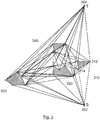
- FIG. 3 shows an example of the complexity reduction.
- dotted line is represented how the target is reached according to the present teachings ignoring three obstacles 320, 330, 340 and only keeps one of them, namely obstacle 310 thus speeding up the finding of the optimal (shortest) path.
- a naive visibility graph algorithm would have generated a complete graph -represented as black segments-with 18 nodes and 71 edges (subpaths), whereas the present approach is able to obtain the shortest path with 4 nodes and 3 edges, shown in dotted line.
- the thicker dotted segments show connected subpaths that form a valid path from S 302 to T 304.
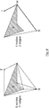
- FIG. 4 shows how using common tangents helps reduce the graph dramatically even for a single obstacle O modelled as a polygon. A significant reduction in the size of the graph leads to lower computation times. Note that the polygon's non-convexity doesn't affect the algorithm because the shortest path between source S and target T is proved to consist of common tangent segments. The thicker segments show the valid (e.g. shortest) path to reach T from S.
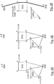
- FIGs. 5A to 5F where a simple scenario is presented including some numerical values for a better appreciation of how the present teachings help to efficiently find the optimal path.
- the scenario basically includes a source S and target T and two obstacles (O) modelled as polygons, a quadrilateral 510 with vertices ABCD and a triangle 520 with vertices EFG.
- the distance between S and T is calculated, which in this case is 10 m (from (0,-5) to (0,5)).
- Such distance along with the S starting point initialize the list of potential waypoints (LPW); so that the LPW initially contains the pair: ([10, S]).
- the graph is expanded from the first point in LPW (in this case, the S point. This task is illustrated in FIGs. 5A and 5B .
- the graph expansion is as follows:
- the graph is expanded from the F node, which is the first point in the LPW.
- the heuristic distance associated to the F node represents that the path S ⁇ F ⁇ Target would be shorter than the path from B if there were no additional obstacles.
- the algorithm expands the graph from B because, according to the heuristic, is the shortest potential path and consequently, it is the first in the list. Again, the BT segment is defined and a new collision with the square obstacle 510 is found.
- the algorithm expands the graph from C, which is the first point in LPW. Following the explained logic, the segment CD is added to the graph and the calculation of the heuristic process provides the next list to continue with the expansion of the graph: [10.246, A], [10.283, D], [12.033, E].
- the last step is shown in FIG. 5F .
- the algorithm expands the graph from the A point (first point in the LPWs).
- the segment AT is collision-free and reaches the target T point. Since the graph is always expanded from the "best-looking" node, the graph expansion can be stopped once the target T is reached.
- the present teachings guarantee the resulting path (S->B->A->Target) can be obtained effortlessly by backtracking the path from the target, which simplifies the problem to a great extent.
Landscapes
- Engineering & Computer Science (AREA)
- Radar, Positioning & Navigation (AREA)
- Remote Sensing (AREA)
- Automation & Control Theory (AREA)
- Physics & Mathematics (AREA)
- General Physics & Mathematics (AREA)
- Aviation & Aerospace Engineering (AREA)
- Navigation (AREA)
Claims (15)
- Computerimplementiertes Verfahren zum Führen eines Fahrzeugs von einem Ursprung (S,302) zu einem Ziel (T,304) in einem Szenario mit Hindernissen, wobei das Verfahren die folgenden Schritte umfasst:a) Festlegen (202, 204) des Ausgangspunkts (S,302) als Startpunkt (S');b) Berechnen (206) einer Teilbahn vom Startpunkt (S') zum Ziel (T,304);c) Erfassen, ob ein Hindernis (O,510,520) die berechnete Teilbahn schneidet;d) Berechnen (208, 210) einer Vielzahl von Teilbahnen zur Umgehung des erfassten Hindernisses (O,510,520), wobei jede Teilbahn den Startpunkt (S') mit einem Wegpunkt (W) einer äußeren Begrenzung des erfassten Hindernisses (O, 510,520) verbindet;e) Erfassen (212), ob ein weiteres Hindernis irgendeine der Vielzahl von Teilbahnen schneidet;f) Wiederholen der Schritte d) - e) für jedes weitere Hindernis;g) Berechnen eines Prioritätswerts (214) für jeden Wegpunkt (W), wobei der Prioritätswert auf folgender Grundlage berechnet wird:der Entfernung zwischen dem Wegpunkt (W) und dem Ziel (T,304) unabhängig von eventuellen Hindernissen zwischen dem Wegpunkt (W) und dem Ziel (T, 304) undder akkumulierten Entfernung vom Ursprung (S,302) zum Wegpunkt (W), wobei die akkumulierte Entfernung mindestens die Entfernung zwischen dem Startpunkt und einem Endpunkt von mindestens einer berechneten hindernisfreien Teilbahn vom Ursprung (S,302) zum Wegpunkt (W) umfasst, wobei die Entfernung gemäß einer vorgegebenen Metrik definiert wird;h) Speichern (216, 218) jedes Wegpunkts und seines zugehörigen Prioritätswerts in einer Liste potenzieller Wegpunkte (LPW);
wobei das Verfahren gekennzeichnet ist durchi) Auswählen (220) des Wegpunkts (W) mit der höchsten Priorität entsprechend einem Minimalwert der Metrik auf der Liste als Startpunkt (S') undj) Wiederholen der Schritte b) bis i), bis das Ziel (T,304) erreicht ist;k) Ermitteln einer optimalen Bahn durch Zurückverfolgen der Wegpunkte vom Ziel (T,304) zum Ursprung (S,302);l) Führen des Fahrzeugs auf der optimalen Bahn. - Computerimplementiertes Verfahren nach Anspruch 1, wobei die äußere Begrenzung eines Hindernisses (O,510,520) durch eine geometrische Figur gebildet wird.
- Computerimplementiertes Verfahren nach Anspruch 2, wobei der Wegpunkt als Schnittpunkt eines gemeinsamen Tangentialsegments mit der dem Hindernis (O,510,520) entsprechenden geometrischen Figur ermittelt wird.
- Computerimplementiertes Verfahren nach Anspruch 3, wobei der Wegpunkt ein Eckpunkt eines Polygons ist.
- Computerimplementiertes Verfahren nach einem der Ansprüche 1 bis 4, wobei die Metrik aus den folgenden ausgewählt ist: Euklidisch, weniger Kraftstoffverbrauch, geringere Höhe, Geodätische Distanz.
- Computerimplementiertes Verfahren nach einem der Ansprüche 1 bis 5, wobei das Hindernis durch einen Nicht-Eintrittsbereich dargestellt wird.
- Computerimplementiertes Verfahren nach einem der Ansprüche 1 bis 6, wobei das Fahrzeug ausgewählt ist zwischen einem UAV, einem Flugzeug, einem Bodenroboter und einem autonomen Landfahrzeug.
- System zum Führen eines Fahrzeugs von einem Ursprung (S,302) zu einem Ziel (T,304) in einem Szenario mit Hindernissen, wobei das System Folgendes umfasst:- eine Bahnberechnungseinheit (110), die dazu ausgelegt ist:a) den Ursprung (S,302) als Startpunkt (S') festzulegen (202, 204);b) eine Teilbahn vom Startpunkt (S') zum Ziel (T,304) zu berechnen (206);- eine Erfassungseinheit (120), die dazu ausgelegt ist
c) zu erfassen, ob ein Hindernis (O,510,520) die berechnete Teilbahn schneidet;- wobei die Bahnberechnungseinheit (110) ferner dazu ausgelegt ist:
d) eine Vielzahl von Teilbahnen zur Umgehung des erfassten Hindernisses (O, 510,520) zu berechnen (208, 210), wobei jede Teilbahn den Startpunkt (S') mit einem Wegpunkt (W) einer äußeren Begrenzung des erfassten Hindernisses (O, 510,520) verbindet;- wobei die Erfassungseinheit (120) ferner dazu ausgelegt iste) zu erfassen (212), ob ein weiteres Hindernis irgendeine der Vielzahl von Teilbahnen schneidet;
wobeif) die Schritte d) - e) für jedes weitere Hindernis wiederholt werden;- eine Auswahleinheit (130), die dazu ausgelegt ist:g) einen Prioritätswert (214) für jeden Wegpunkt (W) zu berechnen, wobei der Prioritätswert auf der Grundlage der Distanz zwischen dem Wegpunkt (W) und dem Ziel (T,304) unabhängig von eventuellen Hindernissen zwischen dem Wegpunkt (W) und dem Ziel (T,304) und der akkumulierten Entfernung vom Ursprung (S,302) zum Wegpunkt (W) berechnet wird, wobei die akkumulierte Entfernung mindestens die Entfernung zwischen dem Startpunkt (S') und einem Endpunkt von mindestens einer berechneten hindernisfreien Teilbahn vom Ursprung (S,302) zum Wegpunkt (W) umfasst, wobei die Entfernung gemäß einer vorgegebenen Metrik definiert wird;h) jeden Wegpunkt (W) und seinen zugehörigen Prioritätswert in einer Liste potenzieller Wegpunkte (LPW) zu speichern (216, 218);wobei das System dadurch gekennzeichnet ist, dass
die Auswahleinheit (130) ferner dazu ausgelegt ist:i) den Wegpunkt (W) mit der höchsten Priorität entsprechend einem Minimalwert der Metrik auf der Liste (LPW) als Startpunkt (S') zu wählen (220) und das System ferner dazu ausgelegt istj) die Schritte b) bis i) zu wiederholen, bis das Ziel (T,304) erreicht ist;- wobei die Bahnberechnungseinheit (110) ferner dazu ausgelegt ist:
k) durch Zurückverfolgen der Wegpunkte (W) vom Ziel (T,304) zum Ursprung (S,302) eine optimale Bahn zu ermitteln;- eine Führungseinheit (140), die dazu ausgelegt ist:
l) das Fahrzeug auf der optimalen Bahn zu führen. - System nach Anspruch 8, wobei die äußere Begrenzung eines Hindernisses (O,510,520) durch eine geometrische Figur gebildet wird.
- System nach Anspruch 9, wobei der Wegpunkt als Schnittpunkt eines gemeinsamen Tangentialsegments mit der dem Hindernis (O,510,520) entsprechenden geometrischen Figur ermittelt wird.
- System nach Anspruch 10, wobei der Wegpunkt ein Eckpunkt eines Polygons ist.
- System nach einem der Ansprüche 8 bis 11, wobei die Metrik aus den folgenden ausgewählt ist: Euklidisch, weniger Kraftstoffverbrauch, geringere Höhe, Geodätische Distanz.
- System nach einem der Ansprüche 8 bis 12, wobei das Hindernis durch einen Nicht-Eintrittsbereich dargestellt wird.
- System nach einem der Ansprüche 8 bis 13, wobei das Fahrzeug ausgewählt ist zwischen einem UAV, einem Flugzeug, einem Bodenroboter und einem autonomen Landfahrzeug.
- Computerprogrammprodukt zum Führen eines Fahrzeugs von einem Ursprung (S,302) zu einem Ziel (T,304) in einem Szenario mit Hindernissen umfassend Computercodebefehle, die bei ihrer Ausführung durch einen Prozessor diesen veranlassen, das Verfahren nach einem der Ansprüche 1 bis 7 durchzuführen.
Priority Applications (2)
| Application Number | Priority Date | Filing Date | Title |
|---|---|---|---|
| EP16382458.4A EP3306431B1 (de) | 2016-10-06 | 2016-10-06 | Computerimplementiertes verfahren und system zum führen eines fahrzeugs in einem szenario mit hindernissen |
| US15/686,974 US10352711B2 (en) | 2016-10-06 | 2017-08-25 | Computer-implemented method and a system for guiding a vehicle within a scenario with obstacles |
Applications Claiming Priority (1)
| Application Number | Priority Date | Filing Date | Title |
|---|---|---|---|
| EP16382458.4A EP3306431B1 (de) | 2016-10-06 | 2016-10-06 | Computerimplementiertes verfahren und system zum führen eines fahrzeugs in einem szenario mit hindernissen |
Publications (2)
| Publication Number | Publication Date |
|---|---|
| EP3306431A1 EP3306431A1 (de) | 2018-04-11 |
| EP3306431B1 true EP3306431B1 (de) | 2021-04-14 |
Family
ID=57211451
Family Applications (1)
| Application Number | Title | Priority Date | Filing Date |
|---|---|---|---|
| EP16382458.4A Active EP3306431B1 (de) | 2016-10-06 | 2016-10-06 | Computerimplementiertes verfahren und system zum führen eines fahrzeugs in einem szenario mit hindernissen |
Country Status (2)
| Country | Link |
|---|---|
| US (1) | US10352711B2 (de) |
| EP (1) | EP3306431B1 (de) |
Families Citing this family (34)
| Publication number | Priority date | Publication date | Assignee | Title |
|---|---|---|---|---|
| US11260855B2 (en) * | 2018-07-17 | 2022-03-01 | Baidu Usa Llc | Methods and systems to predict object movement for autonomous driving vehicles |
| US10564641B2 (en) | 2018-07-20 | 2020-02-18 | May Mobility, Inc. | Multi-perspective system and method for behavioral policy selection by an autonomous agent |
| US10614709B2 (en) | 2018-07-24 | 2020-04-07 | May Mobility, Inc. | Systems and methods for implementing multimodal safety operations with an autonomous agent |
| EP3623759B1 (de) * | 2018-09-14 | 2024-04-17 | The Boeing Company | Computerimplementiertes verfahren und system zur bestimmung eines pfads eines fahrzeugs in einer umgebung mit hindernissen |
| US10809732B2 (en) * | 2018-09-25 | 2020-10-20 | Mitsubishi Electric Research Laboratories, Inc. | Deterministic path planning for controlling vehicle movement |
| GB2577915B (en) * | 2018-10-10 | 2021-06-16 | Dyson Technology Ltd | Path planning |
| US10969470B2 (en) | 2019-02-15 | 2021-04-06 | May Mobility, Inc. | Systems and methods for intelligently calibrating infrastructure devices using onboard sensors of an autonomous agent |
| CN110162095B (zh) * | 2019-06-19 | 2022-05-27 | 西北工业大学 | 一种威胁环境下的无人机快速返航方法 |
| US20220281110A1 (en) * | 2019-08-22 | 2022-09-08 | Sony Group Corporation | Information processing device, information processing method, and program |
| CN110823253B (zh) * | 2019-11-14 | 2022-06-07 | 北京百度网讯科技有限公司 | 基于无人车技术的数据处理方法、装置、设备及存储介质 |
| CN110986955B (zh) * | 2019-12-19 | 2022-04-08 | 拉扎斯网络科技(上海)有限公司 | 机器人路径规划方法、装置、电子设备和存储介质 |
| CN114489044B (zh) * | 2019-12-31 | 2025-01-17 | 深圳引望智能技术有限公司 | 一种轨迹规划方法及装置 |
| CN111326005B (zh) * | 2020-03-04 | 2021-12-28 | 北京百度网讯科技有限公司 | 用于自动驾驶的图像处理方法、装置、计算机设备和介质 |
| CN111283688B (zh) * | 2020-03-23 | 2021-08-10 | 深圳市科瑞技术科技有限公司 | 机器人的避障方法及机器人设备 |
| WO2022006418A1 (en) | 2020-07-01 | 2022-01-06 | May Mobility, Inc. | Method and system for dynamically curating autonomous vehicle policies |
| CN111896005B (zh) * | 2020-07-30 | 2022-02-18 | 江苏金鸽网络科技有限公司 | 一种由室内平面图生成路径的寻路算法 |
| US11797004B2 (en) * | 2020-07-31 | 2023-10-24 | Aurora Flight Sciences Corporation, a subsidiary of The Boeing Company | Causing a robot to execute a mission using a task graph and a task library |
| EP4260009A4 (de) | 2020-12-14 | 2024-11-20 | May Mobility, Inc. | Autonomes fahrzeugsicherheitsplattformsystem und verfahren |
| EP4264181A4 (de) | 2020-12-17 | 2024-10-30 | May Mobility, Inc. | Verfahren und system zur dynamischen aktualisierung einer umgebungsdarstellung eines autonomen agenten |
| CN113805578B (zh) | 2021-02-25 | 2024-07-19 | 京东鲲鹏(江苏)科技有限公司 | 无人车路径优化方法及相关设备 |
| EP4314708A4 (de) | 2021-04-02 | 2024-12-25 | May Mobility, Inc. | Verfahren und system zum betrieb eines autonomen agenten mit unvollständigen umgebungsinformationen |
| WO2022256249A1 (en) * | 2021-06-02 | 2022-12-08 | May Mobility, Inc. | Method and system for remote assistance of an autonomous agent |
| JP2024525459A (ja) * | 2021-06-29 | 2024-07-12 | ユニベルシテ ドゥ カーン ノルマンディ | 自律システムの知識ベース推論のためのシステム及び方法 |
| US11906314B2 (en) | 2021-09-10 | 2024-02-20 | Nec Corporation | System for waypoint selection and method of using |
| WO2023102098A1 (en) | 2021-12-01 | 2023-06-08 | May Mobility, Inc. | Method and system for impact-based operation of an autonomous agent |
| US12296849B2 (en) | 2021-12-02 | 2025-05-13 | May Mobility, Inc. | Method and system for feasibility-based operation of an autonomous agent |
| JP7851524B2 (ja) | 2022-02-14 | 2026-04-27 | メイ モビリティー,インコーポレイテッド | 自律エージェントの条件付き動作のための方法及びシステム |
| CN114442642B (zh) * | 2022-04-02 | 2022-07-15 | 深圳市普渡科技有限公司 | 路径规划方法、装置、计算机设备和存储介质 |
| FR3137981A1 (fr) * | 2022-07-18 | 2024-01-19 | Airbus | Procede et systeme de generation de trajectoire laterale d’un aeronef |
| KR20240038874A (ko) * | 2022-09-16 | 2024-03-26 | 현대모비스 주식회사 | 물류로봇 관제장치 및 그 관제방법 |
| JP2026500243A (ja) | 2022-12-13 | 2026-01-06 | メイ モビリティー,インコーポレイテッド | 自律車両が遭遇し得るリスクを評価し軽減するための方法およびシステム |
| US20250083691A1 (en) * | 2023-09-11 | 2025-03-13 | Gm Cruise Holdings Llc | Spatial path guidance for remote assistance of an autonomous vehicle |
| CN117109625B (zh) * | 2023-10-20 | 2024-01-16 | 湖南大学 | 一种基于改进prm算法的无人驾驶路径规划方法 |
| CN119413180B (zh) * | 2024-12-24 | 2025-04-18 | 江苏盛海智能科技有限公司 | 一种无人车路径规划方法及终端 |
Family Cites Families (6)
| Publication number | Priority date | Publication date | Assignee | Title |
|---|---|---|---|---|
| US7343232B2 (en) | 2003-06-20 | 2008-03-11 | Geneva Aerospace | Vehicle control system including related methods and components |
| US7079943B2 (en) * | 2003-10-07 | 2006-07-18 | Deere & Company | Point-to-point path planning |
| US7228232B2 (en) | 2005-01-24 | 2007-06-05 | International Business Machines Corporation | Navigating a UAV with obstacle avoidance algorithms |
| US8855846B2 (en) * | 2005-10-20 | 2014-10-07 | Jason W. Grzywna | System and method for onboard vision processing |
| FR2964765B1 (fr) * | 2010-09-10 | 2016-04-15 | Thales Sa | Procede de recherche de plus court chemin avec heuristique |
| EP3415868A3 (de) | 2015-07-14 | 2018-12-26 | The Boeing Company | Verfahren und system zur autonomen generierung kürzester seitlicher wege für unbemannte luftfahrtsysteme |
-
2016
- 2016-10-06 EP EP16382458.4A patent/EP3306431B1/de active Active
-
2017
- 2017-08-25 US US15/686,974 patent/US10352711B2/en active Active
Non-Patent Citations (1)
| Title |
|---|
| None * |
Also Published As
| Publication number | Publication date |
|---|---|
| US10352711B2 (en) | 2019-07-16 |
| US20180100743A1 (en) | 2018-04-12 |
| EP3306431A1 (de) | 2018-04-11 |
Similar Documents
| Publication | Publication Date | Title |
|---|---|---|
| EP3306431B1 (de) | Computerimplementiertes verfahren und system zum führen eines fahrzeugs in einem szenario mit hindernissen | |
| KR102049962B1 (ko) | 샘플링기반의 최적 트리를 이용한 경로 계획 방법, 이를 구현하기 위한 프로그램이 저장된 기록매체 및 이를 구현하기 위해 매체에 저장된 컴퓨터프로그램 | |
| EP3623759B1 (de) | Computerimplementiertes verfahren und system zur bestimmung eines pfads eines fahrzeugs in einer umgebung mit hindernissen | |
| KR101409323B1 (ko) | 무인자율차량 및 이의 동적환경 주행경로생성방법 | |
| KR20230083846A (ko) | 3차원 환경에서의 항공 차량 이동노선 계획 방법 | |
| CN110146085A (zh) | 基于建图和快速探索随机树的无人机实时规避重规划方法 | |
| US20240393793A1 (en) | Method for estimating posture of moving object by using big cell grid map, recording medium in which program for implementing same is stored, and computer program stored in medium in order to implement same | |
| CN115326070B (zh) | 城市低空环境下基于三维切线图法的无人机航迹规划方法 | |
| Li et al. | FRTree planner: Robot navigation in cluttered and unknown environments with tree of free regions | |
| CN121409253A (zh) | 基于动态拓扑图构建的无人机实时路径规划方法 | |
| EP4524678A1 (de) | Auswahl eines lokalen roboterplaners | |
| Nagatani et al. | Sensor-based navigation for car-like mobile robots based on a generalized Voronoi graph | |
| CN119803508A (zh) | 机器人的导航方法、存储介质、程序产品及机器人 | |
| CN116954265B (zh) | 局部运动轨迹的重规划方法、装置和电子设备 | |
| CN117289721A (zh) | 避障路径规划和建图方法、装置、电子设备和存储介质 | |
| Wei et al. | A hybrid algorithm of UAV path planning for rescue in bushfire environments | |
| Cieslewski et al. | Exploration without global consistency using local volume consolidation | |
| Chen et al. | TGH-Planner: Topology-Guided Hierarchical Planner for Nonholonomic Robots in 2-D Unknown and Complex Environments | |
| JP7769346B1 (ja) | 移動体、移動体を用いた計測システム、及び移動体を用いた計測方法 | |
| Lazarus et al. | Co-operative unmanned aerial vehicle searching and mapping of complex obstacles using two-dimensional splinegon | |
| CN119197544B (zh) | 一种基于局部探索及全局探索融合的机器人路径规划方法 | |
| Mishenin et al. | Implementation and validation of the cautiousbug algorithm in ros noetic | |
| Lazarus et al. | Terrain based co‐operative UAV mapping of complex obstacles using 2‐D splinegon | |
| CHERIET et al. | TIG*: Enhanced Tangent Intersection Guidance for Efficient 3D UAV Path Planning in Complex Environments | |
| Lin et al. | Fast sampling-based UAV exploration of unknown 3D environments with submodular information gain measure |
Legal Events
| Date | Code | Title | Description |
|---|---|---|---|
| STAA | Information on the status of an ep patent application or granted ep patent |
Free format text: STATUS: EXAMINATION IS IN PROGRESS |
|
| PUAI | Public reference made under article 153(3) epc to a published international application that has entered the european phase |
Free format text: ORIGINAL CODE: 0009012 |
|
| 17P | Request for examination filed |
Effective date: 20161006 |
|
| AK | Designated contracting states |
Kind code of ref document: A1 Designated state(s): AL AT BE BG CH CY CZ DE DK EE ES FI FR GB GR HR HU IE IS IT LI LT LU LV MC MK MT NL NO PL PT RO RS SE SI SK SM TR |
|
| AX | Request for extension of the european patent |
Extension state: BA ME |
|
| GRAP | Despatch of communication of intention to grant a patent |
Free format text: ORIGINAL CODE: EPIDOSNIGR1 |
|
| STAA | Information on the status of an ep patent application or granted ep patent |
Free format text: STATUS: GRANT OF PATENT IS INTENDED |
|
| INTG | Intention to grant announced |
Effective date: 20201201 |
|
| RIN1 | Information on inventor provided before grant (corrected) |
Inventor name: QUEREJETA, CARLOS Inventor name: RODRIGUEZ DIAZ, LUCAS Inventor name: VALLS HERNANDEZ, ERNESTO |
|
| GRAS | Grant fee paid |
Free format text: ORIGINAL CODE: EPIDOSNIGR3 |
|
| GRAA | (expected) grant |
Free format text: ORIGINAL CODE: 0009210 |
|
| STAA | Information on the status of an ep patent application or granted ep patent |
Free format text: STATUS: THE PATENT HAS BEEN GRANTED |
|
| AK | Designated contracting states |
Kind code of ref document: B1 Designated state(s): AL AT BE BG CH CY CZ DE DK EE ES FI FR GB GR HR HU IE IS IT LI LT LU LV MC MK MT NL NO PL PT RO RS SE SI SK SM TR |
|
| REG | Reference to a national code |
Ref country code: GB Ref legal event code: FG4D |
|
| REG | Reference to a national code |
Ref country code: CH Ref legal event code: EP |
|
| REG | Reference to a national code |
Ref country code: DE Ref legal event code: R096 Ref document number: 602016056015 Country of ref document: DE |
|
| REG | Reference to a national code |
Ref country code: IE Ref legal event code: FG4D |
|
| REG | Reference to a national code |
Ref country code: AT Ref legal event code: REF Ref document number: 1382998 Country of ref document: AT Kind code of ref document: T Effective date: 20210515 |
|
| REG | Reference to a national code |
Ref country code: LT Ref legal event code: MG9D |
|
| REG | Reference to a national code |
Ref country code: AT Ref legal event code: MK05 Ref document number: 1382998 Country of ref document: AT Kind code of ref document: T Effective date: 20210414 |
|
| REG | Reference to a national code |
Ref country code: NL Ref legal event code: MP Effective date: 20210414 |
|
| PG25 | Lapsed in a contracting state [announced via postgrant information from national office to epo] |
Ref country code: FI Free format text: LAPSE BECAUSE OF FAILURE TO SUBMIT A TRANSLATION OF THE DESCRIPTION OR TO PAY THE FEE WITHIN THE PRESCRIBED TIME-LIMIT Effective date: 20210414 Ref country code: NL Free format text: LAPSE BECAUSE OF FAILURE TO SUBMIT A TRANSLATION OF THE DESCRIPTION OR TO PAY THE FEE WITHIN THE PRESCRIBED TIME-LIMIT Effective date: 20210414 Ref country code: LT Free format text: LAPSE BECAUSE OF FAILURE TO SUBMIT A TRANSLATION OF THE DESCRIPTION OR TO PAY THE FEE WITHIN THE PRESCRIBED TIME-LIMIT Effective date: 20210414 Ref country code: HR Free format text: LAPSE BECAUSE OF FAILURE TO SUBMIT A TRANSLATION OF THE DESCRIPTION OR TO PAY THE FEE WITHIN THE PRESCRIBED TIME-LIMIT Effective date: 20210414 Ref country code: AT Free format text: LAPSE BECAUSE OF FAILURE TO SUBMIT A TRANSLATION OF THE DESCRIPTION OR TO PAY THE FEE WITHIN THE PRESCRIBED TIME-LIMIT Effective date: 20210414 Ref country code: BG Free format text: LAPSE BECAUSE OF FAILURE TO SUBMIT A TRANSLATION OF THE DESCRIPTION OR TO PAY THE FEE WITHIN THE PRESCRIBED TIME-LIMIT Effective date: 20210714 |
|
| PG25 | Lapsed in a contracting state [announced via postgrant information from national office to epo] |
Ref country code: NO Free format text: LAPSE BECAUSE OF FAILURE TO SUBMIT A TRANSLATION OF THE DESCRIPTION OR TO PAY THE FEE WITHIN THE PRESCRIBED TIME-LIMIT Effective date: 20210714 Ref country code: PT Free format text: LAPSE BECAUSE OF FAILURE TO SUBMIT A TRANSLATION OF THE DESCRIPTION OR TO PAY THE FEE WITHIN THE PRESCRIBED TIME-LIMIT Effective date: 20210816 Ref country code: PL Free format text: LAPSE BECAUSE OF FAILURE TO SUBMIT A TRANSLATION OF THE DESCRIPTION OR TO PAY THE FEE WITHIN THE PRESCRIBED TIME-LIMIT Effective date: 20210414 Ref country code: ES Free format text: LAPSE BECAUSE OF FAILURE TO SUBMIT A TRANSLATION OF THE DESCRIPTION OR TO PAY THE FEE WITHIN THE PRESCRIBED TIME-LIMIT Effective date: 20210414 Ref country code: SE Free format text: LAPSE BECAUSE OF FAILURE TO SUBMIT A TRANSLATION OF THE DESCRIPTION OR TO PAY THE FEE WITHIN THE PRESCRIBED TIME-LIMIT Effective date: 20210414 Ref country code: RS Free format text: LAPSE BECAUSE OF FAILURE TO SUBMIT A TRANSLATION OF THE DESCRIPTION OR TO PAY THE FEE WITHIN THE PRESCRIBED TIME-LIMIT Effective date: 20210414 Ref country code: IS Free format text: LAPSE BECAUSE OF FAILURE TO SUBMIT A TRANSLATION OF THE DESCRIPTION OR TO PAY THE FEE WITHIN THE PRESCRIBED TIME-LIMIT Effective date: 20210814 Ref country code: GR Free format text: LAPSE BECAUSE OF FAILURE TO SUBMIT A TRANSLATION OF THE DESCRIPTION OR TO PAY THE FEE WITHIN THE PRESCRIBED TIME-LIMIT Effective date: 20210715 Ref country code: LV Free format text: LAPSE BECAUSE OF FAILURE TO SUBMIT A TRANSLATION OF THE DESCRIPTION OR TO PAY THE FEE WITHIN THE PRESCRIBED TIME-LIMIT Effective date: 20210414 |
|
| REG | Reference to a national code |
Ref country code: DE Ref legal event code: R097 Ref document number: 602016056015 Country of ref document: DE |
|
| PG25 | Lapsed in a contracting state [announced via postgrant information from national office to epo] |
Ref country code: DK Free format text: LAPSE BECAUSE OF FAILURE TO SUBMIT A TRANSLATION OF THE DESCRIPTION OR TO PAY THE FEE WITHIN THE PRESCRIBED TIME-LIMIT Effective date: 20210414 Ref country code: EE Free format text: LAPSE BECAUSE OF FAILURE TO SUBMIT A TRANSLATION OF THE DESCRIPTION OR TO PAY THE FEE WITHIN THE PRESCRIBED TIME-LIMIT Effective date: 20210414 Ref country code: CZ Free format text: LAPSE BECAUSE OF FAILURE TO SUBMIT A TRANSLATION OF THE DESCRIPTION OR TO PAY THE FEE WITHIN THE PRESCRIBED TIME-LIMIT Effective date: 20210414 Ref country code: SK Free format text: LAPSE BECAUSE OF FAILURE TO SUBMIT A TRANSLATION OF THE DESCRIPTION OR TO PAY THE FEE WITHIN THE PRESCRIBED TIME-LIMIT Effective date: 20210414 Ref country code: SM Free format text: LAPSE BECAUSE OF FAILURE TO SUBMIT A TRANSLATION OF THE DESCRIPTION OR TO PAY THE FEE WITHIN THE PRESCRIBED TIME-LIMIT Effective date: 20210414 Ref country code: RO Free format text: LAPSE BECAUSE OF FAILURE TO SUBMIT A TRANSLATION OF THE DESCRIPTION OR TO PAY THE FEE WITHIN THE PRESCRIBED TIME-LIMIT Effective date: 20210414 |
|
| PLBE | No opposition filed within time limit |
Free format text: ORIGINAL CODE: 0009261 |
|
| STAA | Information on the status of an ep patent application or granted ep patent |
Free format text: STATUS: NO OPPOSITION FILED WITHIN TIME LIMIT |
|
| 26N | No opposition filed |
Effective date: 20220117 |
|
| REG | Reference to a national code |
Ref country code: CH Ref legal event code: PL |
|
| PG25 | Lapsed in a contracting state [announced via postgrant information from national office to epo] |
Ref country code: IS Free format text: LAPSE BECAUSE OF FAILURE TO SUBMIT A TRANSLATION OF THE DESCRIPTION OR TO PAY THE FEE WITHIN THE PRESCRIBED TIME-LIMIT Effective date: 20210814 Ref country code: AL Free format text: LAPSE BECAUSE OF FAILURE TO SUBMIT A TRANSLATION OF THE DESCRIPTION OR TO PAY THE FEE WITHIN THE PRESCRIBED TIME-LIMIT Effective date: 20210414 |
|
| REG | Reference to a national code |
Ref country code: BE Ref legal event code: MM Effective date: 20211031 |
|
| PG25 | Lapsed in a contracting state [announced via postgrant information from national office to epo] |
Ref country code: MC Free format text: LAPSE BECAUSE OF FAILURE TO SUBMIT A TRANSLATION OF THE DESCRIPTION OR TO PAY THE FEE WITHIN THE PRESCRIBED TIME-LIMIT Effective date: 20210414 |
|
| PG25 | Lapsed in a contracting state [announced via postgrant information from national office to epo] |
Ref country code: LU Free format text: LAPSE BECAUSE OF NON-PAYMENT OF DUE FEES Effective date: 20211006 Ref country code: IT Free format text: LAPSE BECAUSE OF FAILURE TO SUBMIT A TRANSLATION OF THE DESCRIPTION OR TO PAY THE FEE WITHIN THE PRESCRIBED TIME-LIMIT Effective date: 20210414 Ref country code: BE Free format text: LAPSE BECAUSE OF NON-PAYMENT OF DUE FEES Effective date: 20211031 |
|
| PG25 | Lapsed in a contracting state [announced via postgrant information from national office to epo] |
Ref country code: LI Free format text: LAPSE BECAUSE OF NON-PAYMENT OF DUE FEES Effective date: 20211031 Ref country code: CH Free format text: LAPSE BECAUSE OF NON-PAYMENT OF DUE FEES Effective date: 20211031 |
|
| PG25 | Lapsed in a contracting state [announced via postgrant information from national office to epo] |
Ref country code: IE Free format text: LAPSE BECAUSE OF NON-PAYMENT OF DUE FEES Effective date: 20211006 |
|
| PG25 | Lapsed in a contracting state [announced via postgrant information from national office to epo] |
Ref country code: HU Free format text: LAPSE BECAUSE OF FAILURE TO SUBMIT A TRANSLATION OF THE DESCRIPTION OR TO PAY THE FEE WITHIN THE PRESCRIBED TIME-LIMIT; INVALID AB INITIO Effective date: 20161006 |
|
| P01 | Opt-out of the competence of the unified patent court (upc) registered |
Effective date: 20230516 |
|
| PG25 | Lapsed in a contracting state [announced via postgrant information from national office to epo] |
Ref country code: CY Free format text: LAPSE BECAUSE OF FAILURE TO SUBMIT A TRANSLATION OF THE DESCRIPTION OR TO PAY THE FEE WITHIN THE PRESCRIBED TIME-LIMIT Effective date: 20210414 |
|
| REG | Reference to a national code |
Ref country code: DE Ref legal event code: R079 Ref document number: 602016056015 Country of ref document: DE Free format text: PREVIOUS MAIN CLASS: G05D0001020000 Ipc: G05D0001430000 |
|
| PG25 | Lapsed in a contracting state [announced via postgrant information from national office to epo] |
Ref country code: MK Free format text: LAPSE BECAUSE OF FAILURE TO SUBMIT A TRANSLATION OF THE DESCRIPTION OR TO PAY THE FEE WITHIN THE PRESCRIBED TIME-LIMIT Effective date: 20210414 |
|
| PG25 | Lapsed in a contracting state [announced via postgrant information from national office to epo] |
Ref country code: MT Free format text: LAPSE BECAUSE OF FAILURE TO SUBMIT A TRANSLATION OF THE DESCRIPTION OR TO PAY THE FEE WITHIN THE PRESCRIBED TIME-LIMIT Effective date: 20210414 |
|
| PG25 | Lapsed in a contracting state [announced via postgrant information from national office to epo] |
Ref country code: TR Free format text: LAPSE BECAUSE OF FAILURE TO SUBMIT A TRANSLATION OF THE DESCRIPTION OR TO PAY THE FEE WITHIN THE PRESCRIBED TIME-LIMIT Effective date: 20210414 |
|
| PGFP | Annual fee paid to national office [announced via postgrant information from national office to epo] |
Ref country code: DE Payment date: 20251029 Year of fee payment: 10 |
|
| PGFP | Annual fee paid to national office [announced via postgrant information from national office to epo] |
Ref country code: GB Payment date: 20251027 Year of fee payment: 10 |
|
| PGFP | Annual fee paid to national office [announced via postgrant information from national office to epo] |
Ref country code: FR Payment date: 20251027 Year of fee payment: 10 |