EP3306475B1 - Systeme und verfahren zur vorhersage von plattenfehlern - Google Patents
Systeme und verfahren zur vorhersage von plattenfehlern Download PDFInfo
- Publication number
- EP3306475B1 EP3306475B1 EP17191480.7A EP17191480A EP3306475B1 EP 3306475 B1 EP3306475 B1 EP 3306475B1 EP 17191480 A EP17191480 A EP 17191480A EP 3306475 B1 EP3306475 B1 EP 3306475B1
- Authority
- EP
- European Patent Office
- Prior art keywords
- failure
- factor
- disk
- bin
- factors
- Prior art date
- Legal status (The legal status is an assumption and is not a legal conclusion. Google has not performed a legal analysis and makes no representation as to the accuracy of the status listed.)
- Active
Links
Images


Classifications
-
- G—PHYSICS
- G06—COMPUTING OR CALCULATING; COUNTING
- G06F—ELECTRIC DIGITAL DATA PROCESSING
- G06F3/00—Input arrangements for transferring data to be processed into a form capable of being handled by the computer; Output arrangements for transferring data from processing unit to output unit, e.g. interface arrangements
- G06F3/06—Digital input from, or digital output to, record carriers, e.g. RAID, emulated record carriers or networked record carriers
- G06F3/0601—Interfaces specially adapted for storage systems
- G06F3/0602—Interfaces specially adapted for storage systems specifically adapted to achieve a particular effect
- G06F3/0614—Improving the reliability of storage systems
- G06F3/0619—Improving the reliability of storage systems in relation to data integrity, e.g. data losses, bit errors
-
- G—PHYSICS
- G06—COMPUTING OR CALCULATING; COUNTING
- G06F—ELECTRIC DIGITAL DATA PROCESSING
- G06F11/00—Error detection; Error correction; Monitoring
- G06F11/008—Reliability or availability analysis
-
- G—PHYSICS
- G06—COMPUTING OR CALCULATING; COUNTING
- G06F—ELECTRIC DIGITAL DATA PROCESSING
- G06F11/00—Error detection; Error correction; Monitoring
- G06F11/30—Monitoring
- G06F11/3003—Monitoring arrangements specially adapted to the computing system or computing system component being monitored
- G06F11/3034—Monitoring arrangements specially adapted to the computing system or computing system component being monitored where the computing system component is a storage system, e.g. DASD based or network based
-
- G—PHYSICS
- G06—COMPUTING OR CALCULATING; COUNTING
- G06F—ELECTRIC DIGITAL DATA PROCESSING
- G06F11/00—Error detection; Error correction; Monitoring
- G06F11/30—Monitoring
- G06F11/34—Recording or statistical evaluation of computer activity, e.g. of down time, of input/output operation ; Recording or statistical evaluation of user activity, e.g. usability assessment
- G06F11/3452—Performance evaluation by statistical analysis
-
- G—PHYSICS
- G06—COMPUTING OR CALCULATING; COUNTING
- G06F—ELECTRIC DIGITAL DATA PROCESSING
- G06F11/00—Error detection; Error correction; Monitoring
- G06F11/30—Monitoring
- G06F11/34—Recording or statistical evaluation of computer activity, e.g. of down time, of input/output operation ; Recording or statistical evaluation of user activity, e.g. usability assessment
- G06F11/3466—Performance evaluation by tracing or monitoring
-
- G—PHYSICS
- G06—COMPUTING OR CALCULATING; COUNTING
- G06F—ELECTRIC DIGITAL DATA PROCESSING
- G06F3/00—Input arrangements for transferring data to be processed into a form capable of being handled by the computer; Output arrangements for transferring data from processing unit to output unit, e.g. interface arrangements
- G06F3/06—Digital input from, or digital output to, record carriers, e.g. RAID, emulated record carriers or networked record carriers
- G06F3/0601—Interfaces specially adapted for storage systems
- G06F3/0628—Interfaces specially adapted for storage systems making use of a particular technique
- G06F3/0653—Monitoring storage devices or systems
-
- G—PHYSICS
- G06—COMPUTING OR CALCULATING; COUNTING
- G06F—ELECTRIC DIGITAL DATA PROCESSING
- G06F3/00—Input arrangements for transferring data to be processed into a form capable of being handled by the computer; Output arrangements for transferring data from processing unit to output unit, e.g. interface arrangements
- G06F3/06—Digital input from, or digital output to, record carriers, e.g. RAID, emulated record carriers or networked record carriers
- G06F3/0601—Interfaces specially adapted for storage systems
- G06F3/0668—Interfaces specially adapted for storage systems adopting a particular infrastructure
- G06F3/0671—In-line storage system
- G06F3/0683—Plurality of storage devices
- G06F3/0689—Disk arrays, e.g. RAID, JBOD
Definitions
- the present disclosure relates to digital storage health monitoring.
- the present disclosure relates to predicting disk failure.
- SMART Self-Monitoring, Analysis and Reporting Technology
- US 9 244 790B discloses a system and method for predicting future disk failures.
- US 2009/0312983A discloses using a metric to evaluate performance impact.
- US2007/0079170A discloses data migration in response to predicted disk failure.
- a system for predicting failure of a disk that is configured to store digital data is provided according to the appended independent claim 1.
- the invention provides a method for predicting failure of a disk that is configured to store digital data according to the appended independent claim 6.
- the embodiments of this disclosure as discussed below are preferably a software algorithm, program or code residing on computer useable medium having control logic for enabling execution on a machine having a computer processor.
- the machine typically includes memory storage configured to provide output from execution of the computer algorithm or program.
- the term "software” is meant to be synonymous with any code or program that can be in a processor of a host computer, regardless of whether the implementation is in hardware, firmware or as a software computer product available on a disc, a memory storage device, or for download from a remote machine.
- the embodiments described herein include such software to implement the equations, relationships and algorithms described below.
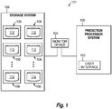
- FIG. 1 depicts a digital storage health monitoring system 101 in which illustrated embodiments of the present disclosure may be implemented.
- the digital storage health monitoring 101 includes a prediction processor system 100 that receives health status information from a monitor device 104 that monitors one or more disk systems 106 provided in a storage system 108.
- the monitor device 104 can include a processing device that executes software to analyze performance of the disk systems 106 in storage system 108 and outputs data or statistics about the performance.
- An example of data about hard disk or solid state disk performance is Self-Monitoring, Analysis and Reporting Technology (SMART) data.
- SMART Self-Monitoring, Analysis and Reporting Technology
- the prediction processor system 100, monitor device 104, and/or storage system 108 can be combined, in any combination, such as by being housed in the same housing, sharing one or more physical components, and/or sharing one or more software components.
- the storage system 108 can include hardware and/or software for mounting and managing systems 106.
- the disk systems 106 include one or more disks 112.
- the disks can use a RAID configuration, without limitation to a particular such configuration.
- Each disk 112 is a disk that is configured to store digital data. Examples of disks 112 include, without limitation, a hard disk or a solid state disk.
- Disk systems 106 can include one or more disk drives (not shown).
- the disk 112 typically provides a large data storage capacity for nonvolatile storage.
- the monitor device 104 can include one or more devices that are installed on the disk systems 106 (e.g., the disk drive) or communicates with the disk systems 106 to gather data or statistics about performance of the disk systems 106.
- the monitor device 104 can include a processing device that is linked to the disk systems 106 via communication links that can include wired and/or wireless links, such as to access logs maintained by the disk drives 112.
- the monitor device 104 and the storage system 108 or disks 112 can communicate, for example, via a network, such as a local access network (LAN) or wide access network (WAN), such as the Internet.
- LAN local access network
- WAN wide access network
- the monitor device 104 can be a virtual device.
- the monitor device executes software to obtain data or statistics related to performance of the disk 112 that can indicate present or future health of the disk 112.
- Monitor device 104 can include hardware, firmware, and/or software used to capture disk data.
- monitor device 104 can include software that calculates disk usage based on number and frequency of reads, writes or other factor that can be used as predictor for a disk failure. A portion of the failure factor can also be determined from logs of equipment that employ disks for data storage. Examples of monitor devices 104 include Tektronix® probes, such as the G10TM and GeoBlade® models, etc.
- monitor device 104 includes hardware, firmware, and/or software that generate SMART data, which can be provided, for example, by disk manufacturers of disks 112.
- the monitor device 104 can include a physical device that is installed on or physically coupled to one or more of the disk systems 106 that calibrates positioning times and spindle speeds of a disk.
- the monitor device 104 monitors the associated disk's 112 performance and outputs data or statistics about the performance.
- the monitor device 104 can access logs, e.g., generated by a probe, that record errors, such as read failure and physical hardware allocation errors.
- the data or statistics about disk performance is referred to herein as health status data.
- the prediction processor system 100 can receive data from the monitor device 104, wherein the term "receive,” as used herein in association with data, refers broadly to getting the data, such as by receiving a transmission, accessing stored data, reading data, or otherwise obtaining data.
- the prediction processor system 100 and the monitor device 104 can communicate via a communication link that can include wired and/or wireless links, wherein a portion, or all, of such links can be included in a network, such as a local access network (LAN) or wide access network (WAN), such as the Internet.
- LAN local access network
- WAN wide access network
- a portion, or all, of the monitor device 104 can be incorporated into the prediction processor system 100, including sharing hardware components.
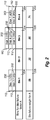
- a table 200 shows factor values 202 for respective disks 204 (e.g., disk systems 106), numbered 1-8, with respect to a particular disk failure factor A.
- Disk failure factors are factors that can be calculated from or included in the health status data output by the monitor device 104. Examples of disk failure factors associated with the disk include age, number of uncorrected read errors, number of uncorrected write errors, non-medium error count, number of sector reallocations, number of defects, SMART health status score, number of delayed reads, number of delayed writes, number of acceleration or deceleration of errors, and results of text mining of log messages. A portion, or all, of the disk failure factors can be calculated from SMART data.
- disk failure factors are labeled A, B, C, D, etc.
- the factor values 202 are determined empirically from the health status data received from the monitor device 104, as described above.
- the factor values 202 are classified into bins 204.
- the bins 204 can have equal sizes or variable sizes. Optimizing bin width based on the factor value 202, such as by using a method for binning by own value, can result in higher accuracy.
- the bins 204 have equal sizes.
- a first bin 204, labeled Bin 1 has factor values 202 for disk failure factor A between 100 to 200; a second bin 204, labeled Bin 2, has factor values 202 for disk failure factor A between 200 to 300; a third bin 204, labeled Bin 3, has factor values 202 for disk failure factor A between 300 to 400; a fourth bin 204, labeled Bin 4, has factor values 202 for disk failure factor A between 400 to 500.
- factor values are provided for disk failure factor A include 100, 120, 310, 370, 380, 420, 450, each of which is classified into the appropriate bin 204.
- Failure factor values can be provided in any form, for example, numeric or text. Binning schemes that provide for allocating a numeric value to bin failure weights associated with each bin can be devised by users.
- Table 200 shows a bin failure weight 206 associated with each bin 204.
- the bin failure weight 206 indicates a degree of failure associated with that bin 204.
- Bin failure weights 206 associated with each bin 204 can be assigned based on observed failure probability of disks 112 included in the bin 204.
- Bins 204 can have a maximum bin failure weight 206 that ranges between 1 (indicating a high likelihood of failure) and a minimum value of 0 (indicating a low likelihood of failure).
- Likelihood of failure values can be calculated and assigned based on user discretion. The values illustrated in FIG. 2 are provided for illustrative purposes only.
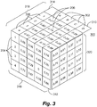
- a three-dimensional matrix 300 is shown.
- the matrix 300 includes bin failure weights 206 based on multiple factors, including disk failure factor 302 shown along a first axis 310, bins 204 shown along a second axis 312, and umbrella failure factor 306 shown along a third axis 314.
- the matrix 300 is shown with four values along each axis 310, 312, 314 for illustrative purposes only. It is to be understood that the matrix 300 is not limited to a particular number of values along any of the axes 312, 314, 316.
- the umbrella failure factors 306 are major disk failure factors that can have an umbrella effect on multiple, or all, of the disk failure factors 302. Usage of umbrella failure factors 306 can be helpful in various scenarios, such as ranking disks within a set of multiple disks by failure probability.
- An example umbrella failure factor 306 is age, since age can have an umbrella effect on other disk failure factors, such as uncorrected read errors and sector reallocations.
- Applying the umbrella failure factors 306 includes assigning bin failure weights 206 to each to the disk failure factors 302 based on a combination of the umbrella failure factor 306 and the disk failure factor 302.
- bin failure weights 206 should not be applied to the umbrella failure factor 306 as a separate disk failure factor 302 (such as, in the example shown in FIG. 3 , a fifth disk failure factor E), since its impact has already been factored in.
- Matrix 300 includes three separate two-dimensional tables, namely first table 316, second table 318, and third table 320.
- first table 316 the bin failure weights 206 entered correspond to disk failure factors 302 (A-D) versus bins 204 (1-4).
- second table 318 the bin failure weights 206 entered correspond to bin weights using umbrella failure factors 306 (1-4) versus disk failure factors 302 (A-D).
- third table 320 the bin failure weights 206 entered correspond to umbrella failure factors 306 (1-4) versus bins 204 (1-4).
- bin weights shown in FIG. 3 are for illustrative purposes only. Other examples of bin weights, without limitation, include a bin failure weight associated with fixed length bins, a bin failure weight associated with variable length bins, a combined failure factor based on the actual factor value and its effect on a particular umbrella factor.
- Tables 316, 318 and 320 show three example methods to calculate bin weights. In table 316, bin weights are obtained based on user discretion. In table 318, bin weights are obtained based on an umbrella failure factor's (e.g., Factor y E) effect on a particular failure factor.
- an umbrella failure factor's e.g., Factor y E
- a complex bin failure weight is obtained that is calculated based on variable bin sizes that use non-uniform binning, or based on cumulative bin weights using an umbrella failure factor, user experience, actual factor values, and/or other weighing and/or binning schemes as selected by the user.
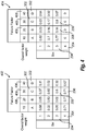
- FIG. 4 shows tables 402 and 404 that include an additional factor overall factor weight 406 that can be applied when predicting disk failure.
- Tables 402 and 404 show an overall factor weight 406 that indicates the contribution of the disk failure factor 302 in predicting failures.
- overall factor weights 406 assigned to disk failure factors 302 labeled A, B, C, and D are 10, 20, 30, and 40, respectively.
- disk failure factor 302, labeled B has twice the contribution to disk failure than disk failure factor 302, labeled A.
- Equation (1) below represents an example formula for calculating a total failure value for a particular disk in the storage system (e.g., storage system 108 in FIG. 1 ).
- Total failure value i ⁇ Bin failure weight for factor A i ⁇ Overall factor weight of factor A + Bin failure factor for factor B i ⁇ Overall factor weight of factor B + ⁇ ⁇ Overaall factor weight of A + Overall factor weight of B + ⁇
- Equation (1) i represents the ith disk. For any particular failure factor, a disk is assigned to only one bin. Once the bin the disk is assigned to for that particular factor is identified, the bin failure weight and bin failure factor that correspond to the bin associated with each failure factor are used to calculate the total failure value for the ith disk using Equation (1).
- Equation (1) uses bin failure weights 206 that are applied to selected disk failure factors 302, which can optionally be combined with umbrella failure factors 306, without limitation to the number of disk failure factors 302 used.
- the bin failure weights can be obtained from any of tables 316, 318 or 320.
- the disk failure factors 302 can be selected based, at least in part, on a standard used by the monitor device 104, such as in SMART data output by the monitor device 104. In a scenario in which the monitor device 104 does not follow a predefined standard, the disk failure factors 302 can be selected to customize the analysis to conform to the health status data output by the monitor device 104. In addition, the disk failure factors 302 can be selected to use only a portion of the health status data output by the monitor device 104.
- Equation (1) can be independent of disk manufacturer and transport protocols used to communicate with the disk. Equation (1) can be used when disk manufacturers and monitor device manufacturers do not comply with conventional reporting standards, such as SMART.
- the disk failure factors 302 used for obtaining the bin failure weights 206 can be selected based on information in the health status data that is identified to correspond to a desired set of disk failure factors.
- the user may desire, for example, to use bin failure weights 206 associated with twelve disk failure factors, however may actually use only ten disk failure factors 302 that could actually be identified in the health status data output by the monitor device 104.
- the user can select to do a cursory analysis based on a single or a small number of disk failure factors 302, or the user can select a relatively large number of disk failure factors 302 for heightened accuracy.
- a user can select to use bin failure weights 206 that are included in a selected table of the first and second tables 316, 318, and 320. For example, a user can select to use Equation (1) with bin failure weights 206 from the second or third tables 318 and 320 that apply the umbrella failure factor 306 to the disk failure factors 302, and thus are based on interdependence between device failure factors 302 and umbrella failure factors 306. Alternatively, the user can select to use Equation (1) with bin failure weights 206 from the first table 316 that does not apply the umbrella failure factor 306 to the disk failure factors 302, treating the device failure factors 302 and umbrella failure factors 306 as independent of one another.
- users can decide to use bin failure weights for one failure factor from one table and another failure factor from another table based on the weighing scheme/binning scheme for the factor. For example, Factor A can use a same binning scheme as table 316 and hence use bin weights entered in table 316, while factor B can use a same combination of a weighing scheme and a binning scheme as table 318 and hence use bin weights entered in table 318.
- a user interface 116 is provided.
- a user can customize the analysis by entering selections via the user interface 116. For example, the user can select which disk failure factors 302 and/or umbrella failure factors 306 to use in the analysis or which bin failure weights to apply (e.g., the bin failure weights included in the first, second or third table, 316, 318, 320).
- the bin failure weights which are determined empirically from observed failure probability of disks in a bin, can be entered via the user interface or provided by a processor.
- a life cycle of a particular disk is known to end at six years.
- the user can attribute disk degradation to age, which in this example corresponds to failure factor E.
- a bin weight of 0 is assigned to bin 1, which corresponds to disks having ages between 0 to 2 years
- a bin weight of 0.5 is assigned to bin 2
- a bin weight of 1.0 is assigned to bin 3, which corresponds to disks having an age between 4 to 6 years.
- a maximum value of 1 indicates a high likelihood of failure
- a minimum value of 0 indicates a low likelihood of failure.
- bin weights for another failure factor can be calculated as if A's value is between 100 to 200, which corresponds to bin 1 for failure factor A in this example.
- A's value is between 100 to 200, which corresponds to bin 1 for failure factor A in this example.
- Those disks assigned to bin 1 that have an age greater than 3 years are assigned a higher bin failure weight (indicating a higher likelihood of failure) than disks assigned to bin 1 that have an age between 0 and 2.
- the result of Equation (1) can be compared to one or more thresholds that qualitatively define the health status of the disk. For example, depending on which threshold is exceeded, the health of the disks can be categorized as belonging to different zones, such as a red, yellow, or green zone.
- the disk analyzed when the result is above a first threshold, the disk analyzed is determined to be in a red zone that indicates the disk needs to be replaced soon; when the result is above a second threshold and below the first threshold, the disk analyzed is determined to be in a yellow zone that indicates that disk recovery methods should be applied to the disk, such as diagnostic and repair systems for verifying file system integrity of a volume, fixing logical file system errors, and/or checking and repairing file systems errors; and when the result is below or equal to the second threshold, the disk analyzed is determined to be in a green zone that indicates the disk is in good health. Users can use this scheme to calculate a mean time to failure (MTTF) for disk(s).
- MTTF mean time to failure
- Equation (1) can be applied to generate a numeric result or a qualitative result.
- the numeric or qualitative results can be output to the user, e.g., via the GUI.
- FIGS. 5 and 6 shown are flowcharts demonstrating implementation of the various exemplary embodiments. It is noted that the order of operations shown in FIGS. 5 and 6 is not required, so in principle, the various operations may be performed out of the illustrated order. Also certain operations may be skipped, different operations may be added or substituted, or selected operations or groups of operations may be performed in a separate application following the embodiments described herein.
- FIG. 5 shows a flowchart of operations performed by the prediction processor system 100 in accordance with embodiments of the disclosure.
- a user selection of one or more disk failure factors is received.
- health status data obtained from monitoring the disk is received.
- data included in the health status data that corresponds to the selected disk failure factors is identified.
- a total failure value for the disk indicative of predicted risk of failure is determined using the identified data.
- a user can select disk failure factors according to the analysis they choose, providing an opportunity to improve accuracy of the analysis by adding disk failure factors that are available in the health status data, such as when new health status data becomes available with advances in technology.
- the method does not depend on a particular standard of health status data or protocols for acquiring the health status data, such as may be imposed by a manufacturer of the disk or disk drive.
- FIG. 6 shows a flowchart of operations performed by the prediction processor system 100 in accordance with further embodiments of the disclosure.
- health status data that indicates a health status of the disk is received.
- the health status data can include factor values that are associated with a plurality of respective disk failure factors.
- an overall factor weight assigned to each disk failure factor is received.
- the overall factor weight indicates the contribution of the associated disk failure factor in predicting a failure.
- a weight factor assigned to each bin of a set of bins is received for each disk failure factor.
- Each bin has an assigned range of factor values.
- the weight factor assigned to each bin indicates a probability of disk failure based on empirical results.
- a bin is determined that has an assigned range of factor values that includes the associated factor value included in the health status data.
- the weight factor is determined that is assigned to the bin that was determined in operation 608.
- a total failure value for the disk is determined, wherein the total failure value is indicative of predicted risk of failure. The total failure value is determined based on, for each disk failure factor, the weight factor determined and the overall factor weight assigned.
- the operations can include receiving a user selection of the disk failure factors, identifying the selected disk failure factors that are present in the health status data, and determining the total failure value for the disk based on the identified disk failure factors.
- the method does not depend on a particular standard of health status data or protocols for acquiring the health status data, such as may be imposed by a manufacturer of the disk or disk drive.
- the health status data can further include a factor value associated with the umbrella failure factor, wherein the umbrella failure factor is a factor that has been determined to be likely to affect the probability of disk failure associated with the respective disk failure factors.
- the total failure value determined can be assigned to a category based on its value, such as a red category that indicates the disk should be replaced soon; a yellow category that indicates further diagnostics (e.g., a checking or scanning diagnostic procedure) should be performed, such as to the filing system; and a green category that indicates the disk has been determined be in good health.
- the operations can include outputting an indication of the category determined.
- embodiments of the present disclosure are directed to a computational technique for determining a disk's level of risk of failure based on health status data for one or more disk failure factors obtained from monitoring the disk, bin placement for each disk failure factor, bin failure weights assigned to the bins, overall factor weight assigned to the disk failure factors, and optionally an overall failure factor that can influence many of the disk failure factors.
- this technique provides flexibility, such that disk failure factors used in the analysis can be selected and identified in the health status data. Total failure value can also be used to derive MTTF for disks.
- aspects of the present disclosure may be embodied as a system, method or computer program product. Accordingly, aspects of the present disclosure may take the form of an entirely hardware embodiment, an entirely software embodiment (including firmware, resident software, micro-code, etc.) or an embodiment combining software and hardware aspects that may all generally be referred to herein as a "circuit,” “module” or “system.” Furthermore, aspects of the present disclosure may take the form of a computer program product embodied in one or more computer readable medium(s) having computer readable program code embodied thereon.
- the computer readable medium may be a computer readable signal medium or a computer readable storage medium.
- a computer readable storage medium may be, for example, but not limited to, an electronic, magnetic, optical, electromagnetic, infrared, or semiconductor system, apparatus, or device, or any suitable combination of the foregoing.
- a computer readable storage medium may be any tangible medium that can contain, or store a program for use by or in connection with an instruction execution system, apparatus, or device.
- a computer readable signal medium may include a propagated data signal with computer readable program code embodied therein, for example, in baseband or as part of a carrier wave. Such a propagated signal may take any of a variety of forms, including, but not limited to, electro-magnetic, optical, or any suitable combination thereof.
- a computer readable signal medium may be any computer readable medium that is not a computer readable storage medium and that can communicate, propagate, or transport a program for use by or in connection with an instruction execution system, apparatus, or device.
- Program code embodied on a computer readable medium may be transmitted using any appropriate medium, including but not limited to wireless, wireline, optical fiber cable, RF, etc., or any suitable combination of the foregoing.
- Computer program code for carrying out operations for aspects of the present disclosure may be written in any combination of one or more programming languages, including an object oriented programming language such as Java, Smalltalk, C++ or the like and conventional procedural programming languages, such as the "C" programming language or similar programming languages.
- the program code may execute entirely on the user's computer, partly on the user's computer, as a stand-alone software package, partly on the user's computer and partly on a remote computer or entirely on the remote computer or server.
- the remote computer may be connected to the user's computer through any type of network, including a local area network (LAN) or a wide area network (WAN), or the connection may be made to an external computer (for example, through the Internet using an Internet Service Provider).
- LAN local area network
- WAN wide area network
- Internet Service Provider for example, AT&T, MCI, Sprint, EarthLink, MSN, GTE, etc.
- These computer program instructions may also be stored in a computer readable medium that can direct a computer, other programmable data processing apparatus, or other devices to function in a particular manner, such that the instructions stored in the computer readable medium produce an article of manufacture including instructions which implement the function/act specified in the flowchart and/or block diagram block or blocks.
- the computer program instructions may also be loaded onto a computer, other programmable data processing apparatus, or other devices to cause a series of operational steps to be performed on the computer, other programmable apparatus or other devices to produce a computer implemented process such that the instructions which execute on the computer or other programmable apparatus provide processes for implementing the functions/acts specified in the flowchart and/or block diagram block or blocks.
- Embodiments of prediction processor system 100 may be implemented or executed by one or more computer systems.
- processor system 702 is illustrated in FIG. 7 .
- processor system 702 may be a server, a mainframe computer system, a workstation, a network computer, a desktop computer, a laptop, or the like.
- Processor system 702 is only one example of a suitable system and is not intended to suggest any limitation as to the scope of use or functionality of embodiments of the disclosure described herein. Regardless, processor system 702 is capable of being implemented and/or performing any of the functionality set forth hereinabove.
- Processor system 702 is operational with numerous other general purpose or special purpose computing system environments or configurations. Examples of well-known computing systems, environments, and/or configurations that may be suitable for use with processor system 702 include, but are not limited to, personal computer systems, server computer systems, thin clients, thick clients, hand-held or laptop devices, multiprocessor systems, microprocessor-based systems, set top boxes, programmable consumer electronics, network PCs, minicomputer systems, mainframe computer systems, and distributed data processing environments that include any of the above systems or devices, and the like.
- Processor system 702 may be described in the general context of computer system-executable instructions, such as program modules, being executed by a computer system.
- program modules may include routines, programs, objects, components, logic, data structures, and so on that perform particular tasks or implement particular abstract data types.
- Processor system 702 may be practiced in distributed data processing environments where tasks are performed by remote processing devices that are linked through a communications network.
- program modules may be located in both local and remote computer system storage media including memory storage devices.
- Processor system 702 is shown in FIG. 7 in the form of a general-purpose computing device.
- the components of processor system 702 may include, but are not limited to, one or more processors or processing units 716, a system memory 728, and a bus 718 that couples various system components including system memory 728 to processor 716.
- Bus 718 represents one or more of any of several types of bus structures, including a memory bus or memory controller, a peripheral bus, an accelerated graphics port, and a processor or local bus using any of a variety of bus architectures.
- bus architectures include Industry Standard Architecture (ISA) bus, Micro Channel Architecture (MCA) bus, Enhanced ISA (EISA) bus, Video Electronics Standards Association (VESA) local bus, and Peripheral Component Interconnect (PCI) bus.
- Processor system 702 typically includes a variety of computer system readable media. Such media may be any available media that is accessible by processor system 702, and it includes both volatile and non-volatile media, removable and non-removable media.
- System memory 728 can include computer system readable media in the form of volatile memory, such as random access memory (RAM) 730 and/or cache memory 732.
- Processor system 702 may further include other removable/non-removable, volatile/non-volatile computer system storage media.
- storage system 734 can be provided for reading from and writing to a non-removable, non-volatile magnetic media (not shown and typically called a "hard drive").
- a magnetic disk drive for reading from and writing to a removable, non-volatile magnetic disk (e.g., a "floppy disk")
- an optical disk drive for reading from or writing to a removable, non-volatile optical disk such as a CD-ROM, DVD-ROM or other optical media
- each can be connected to bus 718 by one or more data media interfaces.
- memory 728 may include at least one program product having a set (e.g., at least one) of program modules that are configured to carry out the functions of embodiments of the disclosure.
- Program/utility 740 having a set (at least one) of program modules 715 may be stored in memory 728 by way of example, and not limitation, as well as an operating system, one or more application programs, other program modules, and program data. Each of the operating system, one or more application programs, other program modules, and program data or some combination thereof, may include an implementation of a networking environment.
- Program modules 715 generally carry out the functions and/or methodologies of embodiments of the disclosure as described herein.
- Processor system 702 may also communicate with one or more external devices 714 such as a keyboard, a pointing device, a display 724, etc.; one or more devices that enable a user to interact with processor system 702; and/or any devices (e.g., network card, modem, etc.) that enable processor system 702 to communicate with one or more other computing devices. Such communication can occur via Input/Output (I/O) interfaces 722. Still yet, processor system 702 can communicate with one or more networks such as a local area network (LAN), a general wide area network (WAN), and/or a public network (e.g., the Internet) via network adapter 720. As depicted, network adapter 720 communicates with the other components of processor system 702 via bus 718.
- LAN local area network
- WAN wide area network
- public network e.g., the Internet
- processor system 702. includes, but are not limited to: microcode, device drivers, redundant processing units, external disk drive arrays, RAID systems, tape drives, and data archival storage systems, etc.
- each block in the flowchart or block diagrams may represent a module, segment, or portion of code, which comprises one or more executable instructions for implementing the specified logical function(s).
- the functions noted in the block may occur out of the order noted in the figures. For example, two blocks shown in succession may, in fact, be executed substantially concurrently, or the blocks may sometimes be executed in the reverse order, depending upon the functionality involved.
Landscapes
- Engineering & Computer Science (AREA)
- Theoretical Computer Science (AREA)
- Physics & Mathematics (AREA)
- General Engineering & Computer Science (AREA)
- General Physics & Mathematics (AREA)
- Quality & Reliability (AREA)
- Computer Hardware Design (AREA)
- Computing Systems (AREA)
- Human Computer Interaction (AREA)
- Life Sciences & Earth Sciences (AREA)
- Bioinformatics & Cheminformatics (AREA)
- Bioinformatics & Computational Biology (AREA)
- Evolutionary Biology (AREA)
- Probability & Statistics with Applications (AREA)
- Mathematical Physics (AREA)
- Computer Security & Cryptography (AREA)
- Debugging And Monitoring (AREA)
Claims (10)
- System zum Vorhersagen eines Ausfalls einer Festplatte (112), die dafür konfiguriert ist, digitale Daten zu speichern, wobei das System umfasst:
ein Informationsverarbeitungssystem (100, 702), das eine Verarbeitungsvorrichtung (716) und eine mit der Verarbeitungsvorrichtung (716) gekoppelten Speichervorrichtung (728) einschließt, wobei die Speichervorrichtung (728) eine Menge von Anweisungen enthält, die, wenn sie durch die Verarbeitungsvorrichtung (716) ausgeführt werden, die Verarbeitungsvorrichtung (716) dazu veranlasst:Zustandsstatusdaten von einer Überwachungseinrichtung (104) zu empfangen, die den Zustandsstatus der Festplatte (112) misst, wobei die Zustandsstatusdaten Faktorwerte (202) einschließen, die mit einer Vielzahl von jeweiligen Festplattenausfallfaktoren (302) assoziiert sind;ein Gesamtfaktorgewicht (406) zu empfangen, das jedem Festplattenausfallfaktor (302) zugewiesen ist, wobei das Gesamtfaktorgewicht einen Beitrag eines zugeordneten Festplattenausfallfaktors (302) zum Vorhersagen des Ausfalls der Festplatte (112) angibt;einen Gewichtsfaktor (206), der jedem Korb (204) einer Menge von Körben zugewiesen ist, für jeden Festplattenausfallfaktor (302) zu empfangen, wobei jeder Korb (204) einen zugewiesenen Bereich von Faktorwerten (202) aufweist, wobei der jedem Korb (204) der Menge von Körben zugewiesene Gewichtsfaktor (206) eine auf empirischen Ergebnissen beruhende Wahrscheinlichkeit des Festplattenausfalls angibt;für jeden Festplattenausfallfaktor (302) einen Korb (204) mit einem zugewiesenen Bereich von Faktorwerten (202) bestimmen, der die zugeordneten Faktorwerte (202) einschließt, die in den Zustandsstatusdaten enthalten sind;für jeden Festplattenausfallfaktor (302) den Gewichtsfaktor (206) bestimmen, der dem bestimmten Korb (204) zugewiesen ist;einen Gesamtausfallwert für die Festplatte (112) zu bestimmen, der ein vorhergesagtes Ausfallrisiko kennzeichnet, und zwar auf der Grundlage des bestimmten Gewichtsfaktors (206) und des zugewiesenen Gesamtfaktorgewichts (406) für jeden Festplattenausfallfaktor (302), undden jedem Korb (204) zugewiesenen Gewichtsfaktor (206) unter Verwendung einer dreidimensionalen Matrix (300) zu bestimmen, worin die Matrix (300) durch getrennte erste (316), zweite (318) und dritte (320) zweidimensionale Tabellen definiert ist, wobei die Matrix (300) den entlang einer ersten Achse (310) gezeigten Festplattenausfallfaktor (302), entlang einer zweiten Achse (312) gezeigte Körbe (204) und einen entlang einer dritten Achse (314) gezeigten übergreifenden Ausfallfaktor (306) einschließt, worin die erste zweidimensionale Tabelle (316) eingegebene Gewichtsfaktoren (206) einschließt, die Festplattenausfallfaktoren (302) gegenüber Körben (204) entsprechen, die zweite zweidimensionale Tabelle (318) eingegebene Gewichtsfaktoren (206) einschließt, die Korbgewichten unter Verwendung von übergreifenden Ausfallfaktoren (306) gegenüber Festplattenausfallfaktoren (302) entsprechen, und die dritte zweidimensionale Tabelle (320) eingegebene Gewichtsfaktoren (206) einschließt, die übergreifenden Ausfallfaktoren (306) gegenüber Körben (204) entsprechen. - System nach Anspruch 1, worin die Menge von Anweisungen, wenn sie durch die Verarbeitungsvorrichtung (716) ausgeführt wird, die Verarbeitungsvorrichtung (716) dazu veranlasst:eine Benutzerauswahl der Festplattenausfallfaktoren (302) zu empfangen;ausgewählte Festplattenausfallfaktoren (302) zu identifizieren, die in den Zustandsstatusdaten vorliegen; undden Gesamtausfallwert für die Festplatte (112) auf der Grundlage der identifizierten Festplattenausfallfaktoren (302) zu bestimmen.
- System nach Anspruch 1:worin die Zustandsstatusdaten ferner einen Faktorwert einschließen, der mit dem übergreifenden Ausfallfaktor (306) assoziiert ist, wobei der übergreifende Ausfallfaktor (306) ein Faktor ist, von dem bestimmt wird, dass er die Wahrscheinlichkeit eines Festplattenausfalls, der mit den jeweiligen Festplattenausfallfaktoren (302) assoziiert ist, wahrscheinlich beeinflusst,worin die empfangenen Gewichtsfaktoren (206), die jedem Korb (204) der Menge von Körben für jeweilige Festplattenausfallfaktoren (302) zugewiesen sind, ferner auf Faktorwerten beruhen, die mit dem übergreifenden Ausfallfaktor (306) assoziiert sind, undworin das Bestimmen des Korbs (204) für jeden Festplattenausfallfaktor (302) das Bestimmen eines Korbs (204), der einen zugewiesenen Bereich von Faktorwerten aufweist, der den Faktorwert einschließt, der in den mit dem übergreifenden Ausfallfaktor (306) assoziierten Zustandsstatusdaten enthalten ist, einschließt.
- System nach Anspruch 1, worin die Menge von Anweisungen, wenn sie durch die Verarbeitungsvorrichtung ausgeführt wird, die Verarbeitungsvorrichtung (716) dazu veranlasst:eine Vielzahl von Kategorien des Gesamtausfallrisikos bereitzustellen, wobei jede Kategorie mit einem anderen Niveau des Festplattenausfallrisikos assoziiert ist und einen zugeordneten Bereich der Gesamtausfallwerte aufweist;diejenige Kategorie aus der Vielzahl von Kategorien zu bestimmen, die einen zugeordneten Bereich von Gesamtausfallwerten aufweist, der den bestimmten Gesamtausfallwert einschließt; undeine Angabe der bestimmten Kategorie auszugeben.
- System nach Anspruch 1, worin das System mindestens eines von a), b) oder c) einschließt:a) die Zustandsstatusdaten werden unter Verwendung von SMART-Protokollen erzeugt;b) die Überwachungseinrichtung (104) schließt eine physische Vorrichtung ein, die mit mindestens einem verbunden ist, nämlich die Festplatte (112) oder ein Festplattenlaufwerk, das mit der Festplatte arbeitet;c) das System umfasst ferner eine oder die Überwachungseinrichtung (104), worin die Überwachungseinrichtung (104) das Betriebsverhalten der Festplatte (112) überwacht und die Zustandsstatusdaten auf der Grundlage der Überwachung ausgibt.
- Computerimplementiertes Verfahren zum Vorhersagen eines Ausfalls einer Festplatte (112), die dafür konfiguriert ist, digitale Daten zu speichern, wobei das Verfahren umfasst:Empfangen von Zustandsstatusdaten, die einen Zustandsstatus der Festplatte (112) angeben, wobei die Zustandsstatusdaten Faktorwerte (202) einschließen, die mit einer Vielzahl von jeweiligen Festplattenausfallfaktoren (302) assoziiert sind;Empfangen eines Gesamtfaktorgewichts (406), das jedem Festplattenausfallfaktor (302) zugewiesen ist und das den Beitrag dieses Faktors zum Vorhersagen eines Ausfalls angibt, wobei das Gesamtfaktorgewicht (406) einen Beitrag eines zugewiesenen Festplattenausfallfaktors (302) zum Vorhersagen eines Ausfalls der Festplatte (112) angibt;für jeden Festplattenausfallfaktor (302) erfolgendes Empfangen eines Gewichtsfaktors (206), der jedem Korb (204) einer Menge von Körben zugewiesen ist, wobei jeder Korb (204) einen zugewiesenen Bereich von Faktorwerten (202) aufweist, wobei der jedem Korb (204) der Menge von Körben zugewiesene Gewichtsfaktor (206) eine auf empirischen Ergebnissen beruhende Wahrscheinlichkeit des Festplattenausfalls angibt;für jeden Festplattenausfallfaktor (302) erfolgendes Bestimmen eines Korbs (204) mit einem zugewiesenen Bereich von Faktorwerten (202), der die zugeordneten Faktorwerte (202) einschließt, die in den Zustandsstatusdaten enthalten sind;für jeden Festplattenausfallfaktor (302) erfolgendes Bestimmen des Gewichtsfaktors (206), der dem bestimmten Korb (204) zugewiesen ist;Bestimmen eines Gesamtausfallwerts für die Festplatte (112), der ein vorhergesagtes Ausfallrisiko kennzeichnet, auf der Grundlage des bestimmten Gewichtsfaktors (206) und des zugewiesenen Gesamtfaktorgewichts (406) für jeden Festplattenausfallfaktor (302), undBestimmen des jedem Korb (204) zugewiesenen Gewichtsfaktors (206) unter Verwendung einer dreidimensionalen Matrix (300), worin die Matrix (300) durch getrennte erste (316), zweite (318) und dritte (320) zweidimensionale Tabellen definiert ist, wobei die Matrix (300) den entlang einer ersten Achse (310) gezeigten Festplattenausfallfaktor (302), entlang einer zweiten Achse (312) gezeigte Körbe (204) und einen entlang einer dritten Achse (314) gezeigten übergreifenden Ausfallfaktor (306) einschließt, worin die erste zweidimensionale Tabelle (316) eingegebene Gewichtsfaktoren (206) einschließt, die Festplattenausfallfaktoren (302) gegenüber Körben (204) entsprechen, die zweite zweidimensionale Tabelle (318) eingegebene Gewichtsfaktoren (206) einschließt, die Korbgewichten unter Verwendung von übergreifenden Ausfallfaktoren (306) gegenüber Festplattenausfallfaktoren (302) entsprechen, und die dritte zweidimensionale Tabelle (320) eingegebene Gewichtsfaktoren (206) einschließt, die übergreifenden Ausfallfaktoren (306) gegenüber Körben (204) entsprechen.
- Verfahren nach Anspruch 6, ferner umfassend:Empfangen einer Benutzerauswahl der Festplattenausfallfaktoren (302); undIdentifizieren ausgewählter Festplattenausfallfaktoren (302), die in den Zustandsstatusdaten vorliegen; undBestimmen des Gesamtausfallwerts für die Festplatte (112) auf der Grundlage der identifizierten Festplattenausfallfaktoren (302).
- Verfahren nach Anspruch 6:worin die Zustandsstatusdaten ferner einen Faktorwert einschließen, der mit dem übergreifenden Ausfallfaktor (306) assoziiert ist, wobei der übergreifende Ausfallfaktor (306) ein Faktor ist, von dem bestimmt wird, dass er die Wahrscheinlichkeit eines Festplattenausfalls, der mit den jeweiligen Festplattenausfallfaktoren (302) assoziiert ist, wahrscheinlich beeinflusst,worin die empfangenen Gewichtsfaktoren (206), die jedem Korb (204) der Menge von Körben für jeweilige Festplattenausfallfaktoren (302) zugewiesen sind, ferner auf Faktorwerten beruhen, die mit dem übergreifenden Ausfallfaktor (306) assoziiert sind, undworin das Bestimmen des Korbs (204) für jeden Festplattenausfallfaktor (302) das Bestimmen eines Korbs (204), der einen zugewiesenen Bereich von Faktorwerten aufweist, der den Faktorwert einschließt, der in den mit dem übergreifenden Ausfallfaktor (306) assoziierten Zustandsstatusdaten enthalten ist, einschließt.
- Verfahren nach Anspruch 6, ferner umfassend:Bereitstellen einer Vielzahl von Kategorien des Gesamtausfallrisikos, wobei jede Kategorie mit einem anderen Niveau des Festplattenausfallrisikos assoziiert ist und einen zugeordneten Bereich der Gesamtausfallwerte aufweist;Bestimmen derjenigen Kategorie aus der Vielzahl von Kategorien, die einen zugeordneten Bereich von Gesamtausfallwerten aufweist, der den bestimmten Gesamtausfallwert einschließt; undAusgeben einer Angabe der bestimmten Kategorie.
- Verfahren nach Anspruch 6, worin das Verfahren mindestens eines von a) oder b) einschließt:a) die Zustandsstatusdaten werden unter Verwendung von SMART-Protokollen erzeugt;b) das Verfahren umfasst: Überwachen der Festplatte (112); und Ausgeben der Zustandsstatusdaten auf der Grundlage der Überwachung.
Applications Claiming Priority (1)
| Application Number | Priority Date | Filing Date | Title |
|---|---|---|---|
| US15/268,221 US10310749B2 (en) | 2016-09-16 | 2016-09-16 | System and method for predicting disk failure |
Publications (3)
| Publication Number | Publication Date |
|---|---|
| EP3306475A2 EP3306475A2 (de) | 2018-04-11 |
| EP3306475A3 EP3306475A3 (de) | 2018-07-11 |
| EP3306475B1 true EP3306475B1 (de) | 2019-11-27 |
Family
ID=59966564
Family Applications (1)
| Application Number | Title | Priority Date | Filing Date |
|---|---|---|---|
| EP17191480.7A Active EP3306475B1 (de) | 2016-09-16 | 2017-09-15 | Systeme und verfahren zur vorhersage von plattenfehlern |
Country Status (2)
| Country | Link |
|---|---|
| US (1) | US10310749B2 (de) |
| EP (1) | EP3306475B1 (de) |
Families Citing this family (24)
| Publication number | Priority date | Publication date | Assignee | Title |
|---|---|---|---|---|
| US10656987B1 (en) * | 2017-04-26 | 2020-05-19 | EMC IP Holding Company LLC | Analysis system and method |
| CN108647136B (zh) * | 2018-05-10 | 2021-05-04 | 南京道熵信息技术有限公司 | 基于smart信息和深度学习的硬盘损坏预测方法及装置 |
| US11099743B2 (en) | 2018-06-29 | 2021-08-24 | International Business Machines Corporation | Determining when to replace a storage device using a machine learning module |
| US11119662B2 (en) | 2018-06-29 | 2021-09-14 | International Business Machines Corporation | Determining when to perform a data integrity check of copies of a data set using a machine learning module |
| US11748185B2 (en) | 2018-06-29 | 2023-09-05 | Microsoft Technology Licensing, Llc | Multi-factor cloud service storage device error prediction |
| US11119850B2 (en) | 2018-06-29 | 2021-09-14 | International Business Machines Corporation | Determining when to perform error checking of a storage unit by using a machine learning module |
| US10734016B2 (en) | 2018-08-21 | 2020-08-04 | Marvell Asia Pte, Ltd. | Pulse-based writing for magnetic storage media |
| CN109697144B (zh) * | 2018-11-22 | 2022-09-23 | 合肥联宝信息技术有限公司 | 一种电子设备的硬盘检测方法及电子设备 |
| CN109828869B (zh) | 2018-12-05 | 2020-12-04 | 南京中兴软件有限责任公司 | 预测硬盘故障发生时间的方法、装置及存储介质 |
| US11450348B2 (en) * | 2019-01-31 | 2022-09-20 | Marvell Asia Pte, Ltd. | Health management for magnetic storage media |
| US12197738B2 (en) | 2019-01-31 | 2025-01-14 | Marvell Asia Pte, Ltd. | Health management for magnetic storage media |
| US11163650B2 (en) * | 2019-09-10 | 2021-11-02 | Druva Inc. | Proactive data recovery system and method |
| RU2019134842A (ru) * | 2019-10-30 | 2021-04-30 | ИЭмСи АйПи ХОЛДИНГ КОМПАНИ, ЛЛС | Система и способ выбора уровня избыточного массива независимых дисков (raid) для экстента сегмента запоминающего устройства |
| US11113163B2 (en) * | 2019-11-18 | 2021-09-07 | International Business Machines Corporation | Storage array drive recovery |
| CN114063881B (zh) * | 2020-07-31 | 2024-07-26 | 阿里巴巴集团控股有限公司 | 分布式系统的磁盘管理方法及装置 |
| CN114115698B (zh) * | 2020-08-27 | 2025-02-21 | 伊姆西Ip控股有限责任公司 | 在存储系统中创建条带的方法、设备和计算机程序产品 |
| CN114492422A (zh) * | 2020-11-13 | 2022-05-13 | 中盈优创资讯科技有限公司 | 一种有监督的多维因素故障愈合流程分析推荐方法及装置 |
| CN112764960A (zh) * | 2021-01-27 | 2021-05-07 | 北京明略昭辉科技有限公司 | 磁盘故障预测、检测及无感知更换的方法及系统 |
| US12174713B2 (en) * | 2021-10-05 | 2024-12-24 | Softiron Limited | Ceph failure and verification |
| CN116680112B (zh) * | 2023-07-28 | 2023-11-03 | 苏州浪潮智能科技有限公司 | 内存状态检测方法、装置、通信设备及存储介质 |
| CN116795655B (zh) * | 2023-08-25 | 2023-11-24 | 深圳市银闪科技有限公司 | 一种基于人工智能的存储设备性能监测系统及方法 |
| CN117215868B (zh) * | 2023-09-06 | 2024-10-15 | 中移互联网有限公司 | 一种磁盘异常检测方法、装置、电子设备及存储介质 |
| CN116895286B (zh) * | 2023-09-11 | 2023-12-15 | 珠海芯烨电子科技有限公司 | 一种打印机故障监控方法以及相关装置 |
| CN119621402B (zh) * | 2024-12-03 | 2025-11-18 | 浪潮商用机器有限公司 | 基于服务器的硬盘共模故障分析方法、装置、设备、介质 |
Family Cites Families (11)
| Publication number | Priority date | Publication date | Assignee | Title |
|---|---|---|---|---|
| US7539597B2 (en) * | 2001-04-10 | 2009-05-26 | Smartsignal Corporation | Diagnostic systems and methods for predictive condition monitoring |
| US7707060B2 (en) * | 2003-08-21 | 2010-04-27 | International Business Machines Corporation | Automatic collection and dissemination of product usage information |
| US20070079170A1 (en) | 2005-09-30 | 2007-04-05 | Zimmer Vincent J | Data migration in response to predicted disk failure |
| US9224147B2 (en) * | 2007-07-16 | 2015-12-29 | Hector Franco | Customer service management system |
| US8019728B2 (en) * | 2008-04-17 | 2011-09-13 | Nec Laboratories America, Inc. | Dynamically quantifying and improving the reliability of distributed data storage systems |
| US7912573B2 (en) | 2008-06-17 | 2011-03-22 | Microsoft Corporation | Using metric to evaluate performance impact |
| TWI517988B (zh) * | 2012-07-18 | 2016-01-21 | 金寶電子工業股份有限公司 | 多功能事務機及自動開閉蓋裝置 |
| KR101307846B1 (ko) * | 2012-08-03 | 2013-09-12 | 주식회사 컴씨스 | 시트 스위치 조립체 |
| US9063966B2 (en) * | 2013-02-01 | 2015-06-23 | International Business Machines Corporation | Selective monitoring of archive and backup storage |
| JP2014228887A (ja) * | 2013-05-17 | 2014-12-08 | 株式会社東芝 | 稼働データ分析装置およびその方法、ならびにプログラム |
| US9244790B1 (en) * | 2013-09-25 | 2016-01-26 | Emc Corporation | System and method for predicting future disk failures |
-
2016
- 2016-09-16 US US15/268,221 patent/US10310749B2/en active Active
-
2017
- 2017-09-15 EP EP17191480.7A patent/EP3306475B1/de active Active
Non-Patent Citations (1)
| Title |
|---|
| None * |
Also Published As
| Publication number | Publication date |
|---|---|
| EP3306475A2 (de) | 2018-04-11 |
| US10310749B2 (en) | 2019-06-04 |
| US20180081571A1 (en) | 2018-03-22 |
| EP3306475A3 (de) | 2018-07-11 |
Similar Documents
| Publication | Publication Date | Title |
|---|---|---|
| EP3306475B1 (de) | Systeme und verfahren zur vorhersage von plattenfehlern | |
| EP4120653A1 (de) | Leistungs- und fehleranalyse von kommunikationsnetzen unter verwendung von lernmodellen mit modellinterpretation | |
| EP2843537B1 (de) | Verfahren und Systeme zur Simulation einer Arbeitsbelastung eines Speichersystems | |
| CN108133732B (zh) | 闪存芯片的性能测试方法、装置、设备及存储介质 | |
| CN113568798B (zh) | 服务器故障定位方法、装置、电子设备及存储介质 | |
| TW201719411A (zh) | 軟體測試系統、方法及其非暫態電腦可讀取紀錄媒體 | |
| CN116340076B (zh) | 硬盘性能测试方法、装置及介质 | |
| CN116662214B (zh) | 基于fio的硬盘垃圾回收方法、装置、系统及介质 | |
| CN116719675B (zh) | 硬盘磨损测试方法、装置及介质 | |
| CN109407655B (zh) | 一种调试芯片的方法及装置 | |
| CN111654405A (zh) | 通信链路的故障节点方法、装置、设备及存储介质 | |
| CN114063881A (zh) | 分布式系统的磁盘管理方法及装置 | |
| CN114741284B (zh) | 任务可靠性评估方法、装置、计算机设备和存储介质 | |
| CN119132379A (zh) | 存储产品可靠性测试方法、装置、设备及存储介质 | |
| CN114048085B (zh) | 一种磁盘故障分析方法、装置、设备及可读存储介质 | |
| US10382311B2 (en) | Benchmarking servers based on production data | |
| CN109726086A (zh) | 测试服务器性能的方法和装置 | |
| CN113849388B (zh) | 一种测试方法和装置、电子设备和存储介质 | |
| Xu et al. | Ml-based modeling to predict i/o performance on different storage sub-systems | |
| CN118312441B (zh) | 一种自动化测试方法、装置、存储介质及系统 | |
| US20210149760A1 (en) | Method and apparatus to identify a problem area in an information handling system based on latencies | |
| CN119252317A (zh) | Ram存储器的测试方法、装置、计算机设备及存储介质 | |
| CN114443378B (zh) | 服务器信号测试系统及方法 | |
| US9582410B2 (en) | Testing software on a computer system | |
| CN116578466A (zh) | 计算存储性能指标数据参考值的方法、装置、设备及介质 |
Legal Events
| Date | Code | Title | Description |
|---|---|---|---|
| PUAI | Public reference made under article 153(3) epc to a published international application that has entered the european phase |
Free format text: ORIGINAL CODE: 0009012 |
|
| STAA | Information on the status of an ep patent application or granted ep patent |
Free format text: STATUS: REQUEST FOR EXAMINATION WAS MADE |
|
| 17P | Request for examination filed |
Effective date: 20170915 |
|
| AK | Designated contracting states |
Kind code of ref document: A2 Designated state(s): AL AT BE BG CH CY CZ DE DK EE ES FI FR GB GR HR HU IE IS IT LI LT LU LV MC MK MT NL NO PL PT RO RS SE SI SK SM TR |
|
| AX | Request for extension of the european patent |
Extension state: BA ME |
|
| PUAL | Search report despatched |
Free format text: ORIGINAL CODE: 0009013 |
|
| RIN1 | Information on inventor provided before grant (corrected) |
Inventor name: AKSHARA, FNU |
|
| AK | Designated contracting states |
Kind code of ref document: A3 Designated state(s): AL AT BE BG CH CY CZ DE DK EE ES FI FR GB GR HR HU IE IS IT LI LT LU LV MC MK MT NL NO PL PT RO RS SE SI SK SM TR |
|
| AX | Request for extension of the european patent |
Extension state: BA ME |
|
| RIC1 | Information provided on ipc code assigned before grant |
Ipc: G06F 11/30 20060101ALI20180604BHEP Ipc: G06F 11/34 20060101ALI20180604BHEP Ipc: G06F 11/00 20060101AFI20180604BHEP |
|
| STAA | Information on the status of an ep patent application or granted ep patent |
Free format text: STATUS: EXAMINATION IS IN PROGRESS |
|
| 17Q | First examination report despatched |
Effective date: 20181030 |
|
| GRAP | Despatch of communication of intention to grant a patent |
Free format text: ORIGINAL CODE: EPIDOSNIGR1 |
|
| STAA | Information on the status of an ep patent application or granted ep patent |
Free format text: STATUS: GRANT OF PATENT IS INTENDED |
|
| INTG | Intention to grant announced |
Effective date: 20190607 |
|
| GRAS | Grant fee paid |
Free format text: ORIGINAL CODE: EPIDOSNIGR3 |
|
| GRAA | (expected) grant |
Free format text: ORIGINAL CODE: 0009210 |
|
| STAA | Information on the status of an ep patent application or granted ep patent |
Free format text: STATUS: THE PATENT HAS BEEN GRANTED |
|
| AK | Designated contracting states |
Kind code of ref document: B1 Designated state(s): AL AT BE BG CH CY CZ DE DK EE ES FI FR GB GR HR HU IE IS IT LI LT LU LV MC MK MT NL NO PL PT RO RS SE SI SK SM TR |
|
| REG | Reference to a national code |
Ref country code: GB Ref legal event code: FG4D |
|
| REG | Reference to a national code |
Ref country code: CH Ref legal event code: EP |
|
| REG | Reference to a national code |
Ref country code: AT Ref legal event code: REF Ref document number: 1207461 Country of ref document: AT Kind code of ref document: T Effective date: 20191215 |
|
| REG | Reference to a national code |
Ref country code: DE Ref legal event code: R096 Ref document number: 602017009067 Country of ref document: DE |
|
| REG | Reference to a national code |
Ref country code: IE Ref legal event code: FG4D |
|
| REG | Reference to a national code |
Ref country code: NL Ref legal event code: MP Effective date: 20191127 |
|
| REG | Reference to a national code |
Ref country code: LT Ref legal event code: MG4D |
|
| PG25 | Lapsed in a contracting state [announced via postgrant information from national office to epo] |
Ref country code: NL Free format text: LAPSE BECAUSE OF FAILURE TO SUBMIT A TRANSLATION OF THE DESCRIPTION OR TO PAY THE FEE WITHIN THE PRESCRIBED TIME-LIMIT Effective date: 20191127 Ref country code: SE Free format text: LAPSE BECAUSE OF FAILURE TO SUBMIT A TRANSLATION OF THE DESCRIPTION OR TO PAY THE FEE WITHIN THE PRESCRIBED TIME-LIMIT Effective date: 20191127 Ref country code: LV Free format text: LAPSE BECAUSE OF FAILURE TO SUBMIT A TRANSLATION OF THE DESCRIPTION OR TO PAY THE FEE WITHIN THE PRESCRIBED TIME-LIMIT Effective date: 20191127 Ref country code: LT Free format text: LAPSE BECAUSE OF FAILURE TO SUBMIT A TRANSLATION OF THE DESCRIPTION OR TO PAY THE FEE WITHIN THE PRESCRIBED TIME-LIMIT Effective date: 20191127 Ref country code: BG Free format text: LAPSE BECAUSE OF FAILURE TO SUBMIT A TRANSLATION OF THE DESCRIPTION OR TO PAY THE FEE WITHIN THE PRESCRIBED TIME-LIMIT Effective date: 20200227 Ref country code: FI Free format text: LAPSE BECAUSE OF FAILURE TO SUBMIT A TRANSLATION OF THE DESCRIPTION OR TO PAY THE FEE WITHIN THE PRESCRIBED TIME-LIMIT Effective date: 20191127 Ref country code: GR Free format text: LAPSE BECAUSE OF FAILURE TO SUBMIT A TRANSLATION OF THE DESCRIPTION OR TO PAY THE FEE WITHIN THE PRESCRIBED TIME-LIMIT Effective date: 20200228 Ref country code: NO Free format text: LAPSE BECAUSE OF FAILURE TO SUBMIT A TRANSLATION OF THE DESCRIPTION OR TO PAY THE FEE WITHIN THE PRESCRIBED TIME-LIMIT Effective date: 20200227 |
|
| PG25 | Lapsed in a contracting state [announced via postgrant information from national office to epo] |
Ref country code: HR Free format text: LAPSE BECAUSE OF FAILURE TO SUBMIT A TRANSLATION OF THE DESCRIPTION OR TO PAY THE FEE WITHIN THE PRESCRIBED TIME-LIMIT Effective date: 20191127 Ref country code: RS Free format text: LAPSE BECAUSE OF FAILURE TO SUBMIT A TRANSLATION OF THE DESCRIPTION OR TO PAY THE FEE WITHIN THE PRESCRIBED TIME-LIMIT Effective date: 20191127 Ref country code: IS Free format text: LAPSE BECAUSE OF FAILURE TO SUBMIT A TRANSLATION OF THE DESCRIPTION OR TO PAY THE FEE WITHIN THE PRESCRIBED TIME-LIMIT Effective date: 20200327 |
|
| PG25 | Lapsed in a contracting state [announced via postgrant information from national office to epo] |
Ref country code: AL Free format text: LAPSE BECAUSE OF FAILURE TO SUBMIT A TRANSLATION OF THE DESCRIPTION OR TO PAY THE FEE WITHIN THE PRESCRIBED TIME-LIMIT Effective date: 20191127 |
|
| PG25 | Lapsed in a contracting state [announced via postgrant information from national office to epo] |
Ref country code: CZ Free format text: LAPSE BECAUSE OF FAILURE TO SUBMIT A TRANSLATION OF THE DESCRIPTION OR TO PAY THE FEE WITHIN THE PRESCRIBED TIME-LIMIT Effective date: 20191127 Ref country code: RO Free format text: LAPSE BECAUSE OF FAILURE TO SUBMIT A TRANSLATION OF THE DESCRIPTION OR TO PAY THE FEE WITHIN THE PRESCRIBED TIME-LIMIT Effective date: 20191127 Ref country code: ES Free format text: LAPSE BECAUSE OF FAILURE TO SUBMIT A TRANSLATION OF THE DESCRIPTION OR TO PAY THE FEE WITHIN THE PRESCRIBED TIME-LIMIT Effective date: 20191127 Ref country code: PT Free format text: LAPSE BECAUSE OF FAILURE TO SUBMIT A TRANSLATION OF THE DESCRIPTION OR TO PAY THE FEE WITHIN THE PRESCRIBED TIME-LIMIT Effective date: 20200419 Ref country code: EE Free format text: LAPSE BECAUSE OF FAILURE TO SUBMIT A TRANSLATION OF THE DESCRIPTION OR TO PAY THE FEE WITHIN THE PRESCRIBED TIME-LIMIT Effective date: 20191127 Ref country code: DK Free format text: LAPSE BECAUSE OF FAILURE TO SUBMIT A TRANSLATION OF THE DESCRIPTION OR TO PAY THE FEE WITHIN THE PRESCRIBED TIME-LIMIT Effective date: 20191127 |
|
| REG | Reference to a national code |
Ref country code: DE Ref legal event code: R097 Ref document number: 602017009067 Country of ref document: DE |
|
| PG25 | Lapsed in a contracting state [announced via postgrant information from national office to epo] |
Ref country code: SK Free format text: LAPSE BECAUSE OF FAILURE TO SUBMIT A TRANSLATION OF THE DESCRIPTION OR TO PAY THE FEE WITHIN THE PRESCRIBED TIME-LIMIT Effective date: 20191127 Ref country code: SM Free format text: LAPSE BECAUSE OF FAILURE TO SUBMIT A TRANSLATION OF THE DESCRIPTION OR TO PAY THE FEE WITHIN THE PRESCRIBED TIME-LIMIT Effective date: 20191127 |
|
| REG | Reference to a national code |
Ref country code: AT Ref legal event code: MK05 Ref document number: 1207461 Country of ref document: AT Kind code of ref document: T Effective date: 20191127 |
|
| PLBE | No opposition filed within time limit |
Free format text: ORIGINAL CODE: 0009261 |
|
| STAA | Information on the status of an ep patent application or granted ep patent |
Free format text: STATUS: NO OPPOSITION FILED WITHIN TIME LIMIT |
|
| 26N | No opposition filed |
Effective date: 20200828 |
|
| PG25 | Lapsed in a contracting state [announced via postgrant information from national office to epo] |
Ref country code: AT Free format text: LAPSE BECAUSE OF FAILURE TO SUBMIT A TRANSLATION OF THE DESCRIPTION OR TO PAY THE FEE WITHIN THE PRESCRIBED TIME-LIMIT Effective date: 20191127 Ref country code: SI Free format text: LAPSE BECAUSE OF FAILURE TO SUBMIT A TRANSLATION OF THE DESCRIPTION OR TO PAY THE FEE WITHIN THE PRESCRIBED TIME-LIMIT Effective date: 20191127 Ref country code: PL Free format text: LAPSE BECAUSE OF FAILURE TO SUBMIT A TRANSLATION OF THE DESCRIPTION OR TO PAY THE FEE WITHIN THE PRESCRIBED TIME-LIMIT Effective date: 20191127 |
|
| PG25 | Lapsed in a contracting state [announced via postgrant information from national office to epo] |
Ref country code: IT Free format text: LAPSE BECAUSE OF FAILURE TO SUBMIT A TRANSLATION OF THE DESCRIPTION OR TO PAY THE FEE WITHIN THE PRESCRIBED TIME-LIMIT Effective date: 20191127 |
|
| REG | Reference to a national code |
Ref country code: CH Ref legal event code: PL |
|
| REG | Reference to a national code |
Ref country code: BE Ref legal event code: MM Effective date: 20200930 |
|
| PG25 | Lapsed in a contracting state [announced via postgrant information from national office to epo] |
Ref country code: LU Free format text: LAPSE BECAUSE OF NON-PAYMENT OF DUE FEES Effective date: 20200915 |
|
| PG25 | Lapsed in a contracting state [announced via postgrant information from national office to epo] |
Ref country code: FR Free format text: LAPSE BECAUSE OF NON-PAYMENT OF DUE FEES Effective date: 20200930 |
|
| PG25 | Lapsed in a contracting state [announced via postgrant information from national office to epo] |
Ref country code: LI Free format text: LAPSE BECAUSE OF NON-PAYMENT OF DUE FEES Effective date: 20200930 Ref country code: IE Free format text: LAPSE BECAUSE OF NON-PAYMENT OF DUE FEES Effective date: 20200915 Ref country code: CH Free format text: LAPSE BECAUSE OF NON-PAYMENT OF DUE FEES Effective date: 20200930 Ref country code: BE Free format text: LAPSE BECAUSE OF NON-PAYMENT OF DUE FEES Effective date: 20200930 |
|
| PG25 | Lapsed in a contracting state [announced via postgrant information from national office to epo] |
Ref country code: TR Free format text: LAPSE BECAUSE OF FAILURE TO SUBMIT A TRANSLATION OF THE DESCRIPTION OR TO PAY THE FEE WITHIN THE PRESCRIBED TIME-LIMIT Effective date: 20191127 Ref country code: MT Free format text: LAPSE BECAUSE OF FAILURE TO SUBMIT A TRANSLATION OF THE DESCRIPTION OR TO PAY THE FEE WITHIN THE PRESCRIBED TIME-LIMIT Effective date: 20191127 Ref country code: CY Free format text: LAPSE BECAUSE OF FAILURE TO SUBMIT A TRANSLATION OF THE DESCRIPTION OR TO PAY THE FEE WITHIN THE PRESCRIBED TIME-LIMIT Effective date: 20191127 |
|
| PG25 | Lapsed in a contracting state [announced via postgrant information from national office to epo] |
Ref country code: MK Free format text: LAPSE BECAUSE OF FAILURE TO SUBMIT A TRANSLATION OF THE DESCRIPTION OR TO PAY THE FEE WITHIN THE PRESCRIBED TIME-LIMIT Effective date: 20191127 Ref country code: MC Free format text: LAPSE BECAUSE OF FAILURE TO SUBMIT A TRANSLATION OF THE DESCRIPTION OR TO PAY THE FEE WITHIN THE PRESCRIBED TIME-LIMIT Effective date: 20191127 |
|
| P01 | Opt-out of the competence of the unified patent court (upc) registered |
Effective date: 20231024 |
|
| PGFP | Annual fee paid to national office [announced via postgrant information from national office to epo] |
Ref country code: DE Payment date: 20250929 Year of fee payment: 9 |
|
| PGFP | Annual fee paid to national office [announced via postgrant information from national office to epo] |
Ref country code: GB Payment date: 20250929 Year of fee payment: 9 |