EP3306576A1 - Verfahren und system zum gesicherten zugang zu einem bestimmten raum mittels eines tragbaren objekts - Google Patents
Verfahren und system zum gesicherten zugang zu einem bestimmten raum mittels eines tragbaren objekts Download PDFInfo
- Publication number
- EP3306576A1 EP3306576A1 EP16192418.8A EP16192418A EP3306576A1 EP 3306576 A1 EP3306576 A1 EP 3306576A1 EP 16192418 A EP16192418 A EP 16192418A EP 3306576 A1 EP3306576 A1 EP 3306576A1
- Authority
- EP
- European Patent Office
- Prior art keywords
- access
- signal
- coded
- portable object
- unlocking device
- Prior art date
- Legal status (The legal status is an assumption and is not a legal conclusion. Google has not performed a legal analysis and makes no representation as to the accuracy of the status listed.)
- Granted
Links
Images


Classifications
-
- B—PERFORMING OPERATIONS; TRANSPORTING
- B60—VEHICLES IN GENERAL
- B60R—VEHICLES, VEHICLE FITTINGS, OR VEHICLE PARTS, NOT OTHERWISE PROVIDED FOR
- B60R25/00—Fittings or systems for preventing or indicating unauthorised use or theft of vehicles
- B60R25/20—Means to switch the anti-theft system on or off
- B60R25/24—Means to switch the anti-theft system on or off using electronic identifiers containing a code not memorised by the user
-
- H—ELECTRICITY
- H04—ELECTRIC COMMUNICATION TECHNIQUE
- H04L—TRANSMISSION OF DIGITAL INFORMATION, e.g. TELEGRAPHIC COMMUNICATION
- H04L63/00—Network architectures or network communication protocols for network security
- H04L63/10—Network architectures or network communication protocols for network security for controlling access to devices or network resources
- H04L63/107—Network architectures or network communication protocols for network security for controlling access to devices or network resources wherein the security policies are location-dependent, e.g. entities privileges depend on current location or allowing specific operations only from locally connected terminals
-
- G—PHYSICS
- G01—MEASURING; TESTING
- G01S—RADIO DIRECTION-FINDING; RADIO NAVIGATION; DETERMINING DISTANCE OR VELOCITY BY USE OF RADIO WAVES; LOCATING OR PRESENCE-DETECTING BY USE OF THE REFLECTION OR RERADIATION OF RADIO WAVES; ANALOGOUS ARRANGEMENTS USING OTHER WAVES
- G01S13/00—Systems using the reflection or reradiation of radio waves, e.g. radar systems; Analogous systems using reflection or reradiation of waves whose nature or wavelength is irrelevant or unspecified
- G01S13/02—Systems using reflection of radio waves, e.g. primary radar systems; Analogous systems
- G01S13/06—Systems determining position data of a target
- G01S13/08—Systems for measuring distance only
- G01S13/32—Systems for measuring distance only using transmission of continuous waves, whether amplitude-, frequency-, or phase-modulated, or unmodulated
-
- G—PHYSICS
- G01—MEASURING; TESTING
- G01S—RADIO DIRECTION-FINDING; RADIO NAVIGATION; DETERMINING DISTANCE OR VELOCITY BY USE OF RADIO WAVES; LOCATING OR PRESENCE-DETECTING BY USE OF THE REFLECTION OR RERADIATION OF RADIO WAVES; ANALOGOUS ARRANGEMENTS USING OTHER WAVES
- G01S13/00—Systems using the reflection or reradiation of radio waves, e.g. radar systems; Analogous systems using reflection or reradiation of waves whose nature or wavelength is irrelevant or unspecified
- G01S13/74—Systems using reradiation of radio waves, e.g. secondary radar systems; Analogous systems
- G01S13/82—Systems using reradiation of radio waves, e.g. secondary radar systems; Analogous systems wherein continuous-type signals are transmitted
- G01S13/825—Systems using reradiation of radio waves, e.g. secondary radar systems; Analogous systems wherein continuous-type signals are transmitted with exchange of information between interrogator and responder
-
- G—PHYSICS
- G06—COMPUTING OR CALCULATING; COUNTING
- G06F—ELECTRIC DIGITAL DATA PROCESSING
- G06F21/00—Security arrangements for protecting computers, components thereof, programs or data against unauthorised activity
- G06F21/30—Authentication, i.e. establishing the identity or authorisation of security principals
- G06F21/31—User authentication
- G06F21/34—User authentication involving the use of external additional devices, e.g. dongles or smart cards
-
- G—PHYSICS
- G07—CHECKING-DEVICES
- G07C—TIME OR ATTENDANCE REGISTERS; REGISTERING OR INDICATING THE WORKING OF MACHINES; GENERATING RANDOM NUMBERS; VOTING OR LOTTERY APPARATUS; ARRANGEMENTS, SYSTEMS OR APPARATUS FOR CHECKING NOT PROVIDED FOR ELSEWHERE
- G07C9/00—Individual registration on entry or exit
- G07C9/00174—Electronically operated locks; Circuits therefor; Nonmechanical keys therefor, e.g. passive or active electrical keys or other data carriers without mechanical keys
- G07C9/00182—Electronically operated locks; Circuits therefor; Nonmechanical keys therefor, e.g. passive or active electrical keys or other data carriers without mechanical keys operated with unidirectional data transmission between data carrier and locks
-
- G—PHYSICS
- G07—CHECKING-DEVICES
- G07C—TIME OR ATTENDANCE REGISTERS; REGISTERING OR INDICATING THE WORKING OF MACHINES; GENERATING RANDOM NUMBERS; VOTING OR LOTTERY APPARATUS; ARRANGEMENTS, SYSTEMS OR APPARATUS FOR CHECKING NOT PROVIDED FOR ELSEWHERE
- G07C9/00—Individual registration on entry or exit
- G07C9/00174—Electronically operated locks; Circuits therefor; Nonmechanical keys therefor, e.g. passive or active electrical keys or other data carriers without mechanical keys
- G07C9/00309—Electronically operated locks; Circuits therefor; Nonmechanical keys therefor, e.g. passive or active electrical keys or other data carriers without mechanical keys operated with bidirectional data transmission between data carrier and locks
-
- G—PHYSICS
- G08—SIGNALLING
- G08C—TRANSMISSION SYSTEMS FOR MEASURED VALUES, CONTROL OR SIMILAR SIGNALS
- G08C17/00—Arrangements for transmitting signals characterised by the use of a wireless electrical link
- G08C17/02—Arrangements for transmitting signals characterised by the use of a wireless electrical link using a radio link
-
- H—ELECTRICITY
- H04—ELECTRIC COMMUNICATION TECHNIQUE
- H04W—WIRELESS COMMUNICATION NETWORKS
- H04W12/00—Security arrangements; Authentication; Protecting privacy or anonymity
- H04W12/08—Access security
-
- H—ELECTRICITY
- H04—ELECTRIC COMMUNICATION TECHNIQUE
- H04W—WIRELESS COMMUNICATION NETWORKS
- H04W56/00—Synchronisation arrangements
- H04W56/0055—Synchronisation arrangements determining timing error of reception due to propagation delay
- H04W56/0065—Synchronisation arrangements determining timing error of reception due to propagation delay using measurement of signal travel time
- H04W56/009—Closed loop measurements
-
- G—PHYSICS
- G01—MEASURING; TESTING
- G01S—RADIO DIRECTION-FINDING; RADIO NAVIGATION; DETERMINING DISTANCE OR VELOCITY BY USE OF RADIO WAVES; LOCATING OR PRESENCE-DETECTING BY USE OF THE REFLECTION OR RERADIATION OF RADIO WAVES; ANALOGOUS ARRANGEMENTS USING OTHER WAVES
- G01S13/00—Systems using the reflection or reradiation of radio waves, e.g. radar systems; Analogous systems using reflection or reradiation of waves whose nature or wavelength is irrelevant or unspecified
- G01S13/74—Systems using reradiation of radio waves, e.g. secondary radar systems; Analogous systems
- G01S13/76—Systems using reradiation of radio waves, e.g. secondary radar systems; Analogous systems wherein pulse-type signals are transmitted
-
- G—PHYSICS
- G01—MEASURING; TESTING
- G01S—RADIO DIRECTION-FINDING; RADIO NAVIGATION; DETERMINING DISTANCE OR VELOCITY BY USE OF RADIO WAVES; LOCATING OR PRESENCE-DETECTING BY USE OF THE REFLECTION OR RERADIATION OF RADIO WAVES; ANALOGOUS ARRANGEMENTS USING OTHER WAVES
- G01S13/00—Systems using the reflection or reradiation of radio waves, e.g. radar systems; Analogous systems using reflection or reradiation of waves whose nature or wavelength is irrelevant or unspecified
- G01S13/74—Systems using reradiation of radio waves, e.g. secondary radar systems; Analogous systems
- G01S13/82—Systems using reradiation of radio waves, e.g. secondary radar systems; Analogous systems wherein continuous-type signals are transmitted
-
- G—PHYSICS
- G07—CHECKING-DEVICES
- G07C—TIME OR ATTENDANCE REGISTERS; REGISTERING OR INDICATING THE WORKING OF MACHINES; GENERATING RANDOM NUMBERS; VOTING OR LOTTERY APPARATUS; ARRANGEMENTS, SYSTEMS OR APPARATUS FOR CHECKING NOT PROVIDED FOR ELSEWHERE
- G07C9/00—Individual registration on entry or exit
- G07C9/00174—Electronically operated locks; Circuits therefor; Nonmechanical keys therefor, e.g. passive or active electrical keys or other data carriers without mechanical keys
- G07C9/00309—Electronically operated locks; Circuits therefor; Nonmechanical keys therefor, e.g. passive or active electrical keys or other data carriers without mechanical keys operated with bidirectional data transmission between data carrier and locks
- G07C2009/00317—Electronically operated locks; Circuits therefor; Nonmechanical keys therefor, e.g. passive or active electrical keys or other data carriers without mechanical keys operated with bidirectional data transmission between data carrier and locks keyless data carrier having only one limited data transmission range
- G07C2009/00333—Electronically operated locks; Circuits therefor; Nonmechanical keys therefor, e.g. passive or active electrical keys or other data carriers without mechanical keys operated with bidirectional data transmission between data carrier and locks keyless data carrier having only one limited data transmission range and the lock having more than one limited data transmission ranges
-
- G—PHYSICS
- G07—CHECKING-DEVICES
- G07C—TIME OR ATTENDANCE REGISTERS; REGISTERING OR INDICATING THE WORKING OF MACHINES; GENERATING RANDOM NUMBERS; VOTING OR LOTTERY APPARATUS; ARRANGEMENTS, SYSTEMS OR APPARATUS FOR CHECKING NOT PROVIDED FOR ELSEWHERE
- G07C9/00—Individual registration on entry or exit
- G07C9/00174—Electronically operated locks; Circuits therefor; Nonmechanical keys therefor, e.g. passive or active electrical keys or other data carriers without mechanical keys
- G07C9/00309—Electronically operated locks; Circuits therefor; Nonmechanical keys therefor, e.g. passive or active electrical keys or other data carriers without mechanical keys operated with bidirectional data transmission between data carrier and locks
- G07C2009/00365—Electronically operated locks; Circuits therefor; Nonmechanical keys therefor, e.g. passive or active electrical keys or other data carriers without mechanical keys operated with bidirectional data transmission between data carrier and locks in combination with a wake-up circuit
- G07C2009/00373—Electronically operated locks; Circuits therefor; Nonmechanical keys therefor, e.g. passive or active electrical keys or other data carriers without mechanical keys operated with bidirectional data transmission between data carrier and locks in combination with a wake-up circuit whereby the wake-up circuit is situated in the lock
-
- G—PHYSICS
- G07—CHECKING-DEVICES
- G07C—TIME OR ATTENDANCE REGISTERS; REGISTERING OR INDICATING THE WORKING OF MACHINES; GENERATING RANDOM NUMBERS; VOTING OR LOTTERY APPARATUS; ARRANGEMENTS, SYSTEMS OR APPARATUS FOR CHECKING NOT PROVIDED FOR ELSEWHERE
- G07C9/00—Individual registration on entry or exit
- G07C9/00174—Electronically operated locks; Circuits therefor; Nonmechanical keys therefor, e.g. passive or active electrical keys or other data carriers without mechanical keys
- G07C9/00309—Electronically operated locks; Circuits therefor; Nonmechanical keys therefor, e.g. passive or active electrical keys or other data carriers without mechanical keys operated with bidirectional data transmission between data carrier and locks
- G07C2009/00388—Electronically operated locks; Circuits therefor; Nonmechanical keys therefor, e.g. passive or active electrical keys or other data carriers without mechanical keys operated with bidirectional data transmission between data carrier and locks code verification carried out according to the challenge/response method
- G07C2009/00396—Electronically operated locks; Circuits therefor; Nonmechanical keys therefor, e.g. passive or active electrical keys or other data carriers without mechanical keys operated with bidirectional data transmission between data carrier and locks code verification carried out according to the challenge/response method starting with prompting the keyless data carrier
-
- G—PHYSICS
- G07—CHECKING-DEVICES
- G07C—TIME OR ATTENDANCE REGISTERS; REGISTERING OR INDICATING THE WORKING OF MACHINES; GENERATING RANDOM NUMBERS; VOTING OR LOTTERY APPARATUS; ARRANGEMENTS, SYSTEMS OR APPARATUS FOR CHECKING NOT PROVIDED FOR ELSEWHERE
- G07C9/00—Individual registration on entry or exit
- G07C9/00174—Electronically operated locks; Circuits therefor; Nonmechanical keys therefor, e.g. passive or active electrical keys or other data carriers without mechanical keys
- G07C9/00309—Electronically operated locks; Circuits therefor; Nonmechanical keys therefor, e.g. passive or active electrical keys or other data carriers without mechanical keys operated with bidirectional data transmission between data carrier and locks
- G07C2009/00412—Electronically operated locks; Circuits therefor; Nonmechanical keys therefor, e.g. passive or active electrical keys or other data carriers without mechanical keys operated with bidirectional data transmission between data carrier and locks the transmitted data signal being encrypted
-
- G—PHYSICS
- G07—CHECKING-DEVICES
- G07C—TIME OR ATTENDANCE REGISTERS; REGISTERING OR INDICATING THE WORKING OF MACHINES; GENERATING RANDOM NUMBERS; VOTING OR LOTTERY APPARATUS; ARRANGEMENTS, SYSTEMS OR APPARATUS FOR CHECKING NOT PROVIDED FOR ELSEWHERE
- G07C9/00—Individual registration on entry or exit
- G07C9/00174—Electronically operated locks; Circuits therefor; Nonmechanical keys therefor, e.g. passive or active electrical keys or other data carriers without mechanical keys
- G07C9/00309—Electronically operated locks; Circuits therefor; Nonmechanical keys therefor, e.g. passive or active electrical keys or other data carriers without mechanical keys operated with bidirectional data transmission between data carrier and locks
- G07C2009/00555—Electronically operated locks; Circuits therefor; Nonmechanical keys therefor, e.g. passive or active electrical keys or other data carriers without mechanical keys operated with bidirectional data transmission between data carrier and locks comprising means to detect or avoid relay attacks
-
- G—PHYSICS
- G07—CHECKING-DEVICES
- G07C—TIME OR ATTENDANCE REGISTERS; REGISTERING OR INDICATING THE WORKING OF MACHINES; GENERATING RANDOM NUMBERS; VOTING OR LOTTERY APPARATUS; ARRANGEMENTS, SYSTEMS OR APPARATUS FOR CHECKING NOT PROVIDED FOR ELSEWHERE
- G07C9/00—Individual registration on entry or exit
- G07C9/00174—Electronically operated locks; Circuits therefor; Nonmechanical keys therefor, e.g. passive or active electrical keys or other data carriers without mechanical keys
- G07C2009/00753—Electronically operated locks; Circuits therefor; Nonmechanical keys therefor, e.g. passive or active electrical keys or other data carriers without mechanical keys operated by active electrical keys
- G07C2009/00769—Electronically operated locks; Circuits therefor; Nonmechanical keys therefor, e.g. passive or active electrical keys or other data carriers without mechanical keys operated by active electrical keys with data transmission performed by wireless means
- G07C2009/00793—Electronically operated locks; Circuits therefor; Nonmechanical keys therefor, e.g. passive or active electrical keys or other data carriers without mechanical keys operated by active electrical keys with data transmission performed by wireless means by Hertzian waves
-
- G—PHYSICS
- G07—CHECKING-DEVICES
- G07C—TIME OR ATTENDANCE REGISTERS; REGISTERING OR INDICATING THE WORKING OF MACHINES; GENERATING RANDOM NUMBERS; VOTING OR LOTTERY APPARATUS; ARRANGEMENTS, SYSTEMS OR APPARATUS FOR CHECKING NOT PROVIDED FOR ELSEWHERE
- G07C2209/00—Indexing scheme relating to groups G07C9/00 - G07C9/38
- G07C2209/06—Involving synchronization or resynchronization between transmitter and receiver; reordering of codes
-
- G—PHYSICS
- G08—SIGNALLING
- G08C—TRANSMISSION SYSTEMS FOR MEASURED VALUES, CONTROL OR SIMILAR SIGNALS
- G08C2201/00—Transmission systems of control signals via wireless link
- G08C2201/60—Security, fault tolerance
- G08C2201/62—Rolling code
Definitions
- the invention relates to a method of secure access to a specific space, such as to a vehicle, by means of a personalized portable object, such as a personalized electronic key.
- the invention relates to a secure access system for implementing the secure access method.
- An interrogation signal may first be transmitted from an authorization device for access or unlocking the vehicle to the personalized electronic key. Upon receipt of this interrogation signal, the electronic key can be activated and a calculation of a response signal is performed in said electronic key before a coded transmission to the vehicle access authorization device. A check is subsequently made in the access device of the vehicle to determine if the key is well recognized for the opening of said vehicle.
- the device for unlocking the vehicle For the control of access for example to a vehicle by means of an electronic intelligent key, it can be first activated the device for unlocking the vehicle by a mechanical action for example on the door handle of the vehicle. From this moment, the unlocking device transmits a coded interrogation signal, which is received by the electronic key in order to activate it.
- the electronic key can be powered by its own power source, such as a battery. Generally this interrogation signal is transmitted from the vehicle to a low carrier frequency, while the coded response signal of the electronic key is transmitted at a high carrier frequency.
- the electronic key comprises a processing unit or a digital processing unit, which is connected to storage means in which are stored for example an encryption algorithm and / or an identification code for access to the vehicle. Once activated by the coded interrogation signal, the electronic key transmits its coded identification signal to the vehicle, for a control of locking or unlocking parts or functions of the vehicle.
- a response signal is automatically transmitted to the vehicle based on an interrogation signal received from the vehicle.
- the key must be in a restricted area around the vehicle to be able to receive this interrogation signal from the vehicle.
- the key transmits a response signal to the vehicle, if the interrogation signal has been recognized by the key. This response signal thus makes it possible to control the locking or unlocking of parts or functions of the vehicle.
- the reception limits of the signals are determined by the propagation characteristics of the radio frequency signals used for information exchanges and by the characteristics of transmitted power and sensitivity of the transceivers used in the vehicle and in the key.
- the restricted area around the vehicle is generally defined by a minimum received power threshold.
- a first intermediate relay of a first ill-intentioned person is near the vehicle to receive a vehicle interrogation signal.
- This interrogation signal is converted into a radiofrequency signal for transmission to a second intermediate relay of a second ill-intentioned person, who is close to the holder of the electronic key personalized to the vehicle to open and start.
- the second intermediate relay again converts the radio frequency signal of the first intermediate relay into a new low frequency interrogation signal.
- the personalized electronic key carried by the person authorized to access the vehicle receives the new interrogation signal and transmits after recognition of this interrogation signal, a coded high frequency response identification signal.
- This radio frequency response signal of the electronic key can be received directly by the vehicle unlocking device, if the distance to the vehicle is low, for example less than 50 m. On the other hand, if the distance between the electronic key and the vehicle is much greater, for example above 1 km, there must still be an exchange of radiofrequency signals from the key and via the two intermediary relays at the destination. of the vehicle
- the secure access systems known from the state of the art encounter several problems to ensure the opening of the vehicle only by the personalized electronic key. It is generally difficult to determine in particular the distance separating the electronic key of the vehicle to allow the opening of the vehicle only by the electronic key at short distance from the vehicle. This is a disadvantage of secure access systems of the state of the art.
- the patent EP 673 003 B1 describes a system for secure access to a vehicle by means of an electronic key. Following an action on the handle of the vehicle, the unlocking device of the vehicle transmits a coded interrogation signal for the key, which receives it and transmits a coded response signal to the unlocking device. In case of coincidence between the response code transmitted by the key and a set code of the unlocking device, access authorization to the vehicle is performed. A distance sensing device is further provided for measuring the distance between the key and the vehicle to allow the key to transmit the response code only to the vicinity of the vehicle. Such a secure access system does not overcome any intermediary relays for the unauthorized opening of the vehicle, which is a drawback.
- the patent US 6,538,560 B1 discloses a system for accessing a device for unlocking a vehicle via a transponder electronic key.
- the vehicle device transmits a low frequency coded signal to activate the electronic key and enable it to activate its high frequency transmission and reception unit. Subsequently, a coded high frequency interrogation signal is transmitted and received by the key, which must check its validity. Low frequency coded signal processing is performed in the key to enable transmission of a high frequency coded response signal, taking into account the transmitter identification.
- the vehicle device receives the high frequency coded signal from the key to check its validity and allow access to the vehicle if so.
- a processing of the coded signal received from the vehicle unlocking device must be done in the key, which requires a circuitry in the complicated key and increases the power consumption of the battery-powered key, which is a drawback.
- the invention therefore aims to provide a method of secure access to a specific space, by means of a personalized portable object to overcome the disadvantages of the state of the art, for easy and safe access to the determined space via the portable object when transmitting at least one response signal.
- the invention relates to a method of secure access to a determined space, by means of a personalized portable object, which comprises the characteristics mentioned in the independent claim 1.
- An advantage of the method lies in the fact that communication times or flight times are determined by signals transmitted between the access device of a determined space and the personalized portable object.
- the transmitted coded signals can be at high speed, for example at 26 Mbps or 125 Mbps.
- the data flanks in the transmitted and received signal are steeper than with average data rates.
- greater accuracy in determining the distance between the portable object and the access or unlocking device can be obtained. This ensures greater security to allow access to the space determined by a custom portable object.
- signal reception windows make it possible to completely receive the response signal transmitted by the portable object or by the unlocking device. This makes it possible to prevent access to the space determined by intermediary relays in relation to the interrogated portable object.
- a large part of the secure access control of the portable object, such as the electronic key is performed in a digital signal processing unit in the device for accessing or unlocking the determined space, such as a vehicle .
- the communication link used is narrowband type mainly on a single communication frequency, this simplifies also the radio frequency components used.
- the dongle is only activated at the moment of secure access control to the vehicle.
- the secure access system uses narrowband radiofrequency technology, which can be implemented in unlicensed industrial, scientific and medical (ISM) bands.
- the system has narrowband antennas, which have a higher gain than the antennas of a UWB system, making the system of the present invention for implementing the secure access method more economical than UWB technology. .
- the invention also relates to a secure access system for implementing the secure access method, which comprises the features mentioned in the independent claim 15.
- the figure 1 represents an embodiment of the secure access system 1 to a determined space of a portable object for the implementation of the secure access method.
- the determined space is a vehicle provided with an access or unlocking device 2 of the vehicle, and the portable object is preferably an electronic intelligent key 3 for be carried by a user of the vehicle.
- the portable object 3 can also be a card or a badge, a watch, a ring, a mobile phone or any other object that may include an electronic circuit capable of establishing communication with the access or unlocking device. 2.
- the distance separating the personalized electronic key 3 from the access or unlocking device 2 must be accurately detected.
- a transmission and reception in time or delayed shift of control radio signals or data, which can be coded are effected from the unlocking device 2 to the electronic key 3 and vice versa.
- a merging of the distance information in a coded response signal of the electronic key 3 transmitted to the unlocking device 2 can also be performed to prevent any intermediate relay attack.
- a digital signal processing is performed in the unlocking device 2 so as to recognize the electronic key 3, and partly in the electronic key 3, to allow the opening and start of the vehicle. It is thus precisely determined in the unlocking device 2, the flight time of the signals between the device and the key and vice versa, and therefore the distance separating the access device and the electronic key to allow access to the vehicle. .
- the access or unlocking device 2 of the access system 1 comprises in particular a transmitter 21, a receiver 22 and at least one digital signal processing unit 25, which is connected to the transmitter 21 and to the receiver 22.
- a single antenna 26 is connected to the transmitter 21 and to the receiver 22 via a switching element 120.
- the switching element 120 is a two-input multiplexer respectively connected to the transmitter 21 and the receiver 22. and an output connected to the antenna 26.
- This multiplexer 120 is controlled by the processing unit 25 to allow either the transmission of high frequency signals by the antenna 26 from the transmitter 21, or the reception of high-frequency signals. frequency by the antenna 26 to the receiver 22.
- a local oscillator 23, which is preferably a crystal resonator oscillator 24, is also provided to clock the operations of the device. f unlocking 2.
- the digital processing unit 25 may comprise, not shown, a microprocessor clocked by the local oscillator 23, a multi-register memory, a symmetrical or asymmetrical encryption system with a random number generator, as well as a system for managing the data. encryption keys.
- the digital processing unit 25 may further comprise, not shown, an ADC digital analog converter for converting the intermediate signals into intermediate digital signals, an envelope detector of the intermediate digital signals, a delay element, a frequency modulation generator of signals.
- the digital processing unit 25 further comprises a digital-to-analog converter DAC for converting digital signals to be transmitted to the electronic key 3.
- the electronic key 3 of the access system 1 comprises in particular a transmitter 31, a receiver 32 and at least one digital processing unit 35, which is connected to the transmitter 31 and the receiver 32.
- a single antenna 36 is connected to the transmitter 31 and to the receiver 32 via a switching element 150.
- the switching element 150 is a two-input multiplexer respectively connected to the transmitter 31 and the receiver 32 and to an output connected to the Antenna 36.
- This multiplexer 150 is controlled by the digital processing unit 35 to enable either the transmission of high frequency signals by the antenna 36 from the transmitter 31 or the reception of high frequency signals by the antenna 36. to the receiver 32 as for the access or unlocking device 2.
- a local oscillator 33 which is preferably a crystal resonator oscillator 34, is also provided to clock the operations in the electronic key 3 and mainly the processing via the digital processing unit 35. Oscillation of the local oscillator 33 may be at a frequency of the order of 26 MHz or at a frequency divided by a set of divisors by two.
- This local oscillator 33 is similar to the local oscillator 23 with crystal resonator 24 of the unlocking device 2.
- the frequency of the oscillation signal is substantially similar to ⁇ 40 ppm. This can make it possible to have a good synchronization of treatment in the unlocking device 2 and in the key 3 after an initial calibration step or during the secure access method explained below.
- the digital processing unit 35 may comprise, not represented, a processor or a state machine clocked by the local oscillator 33, a multi-register memory, a symmetrical or asymmetrical encryption system with a random number generator, as well as a encryption key management system.
- the digital processing unit 35 may also comprise, not shown, an ADC digital analog converter for converting the intermediate signals into intermediate digital signals, an envelope detector of the intermediate digital signals, a delay element, a frequency modulation generator. of signals.
- the digital processing unit 35 further comprises a digital-to-analog converter for converting digital signals to be transmitted to the unlocking device 2.
- the transmitter 21 of the access or unlocking device 2 is capable of transmitting a control signal or data by the antenna 26 to the antenna 36 of the electronic key 3 explained in detail below.
- the activation signal transmitted by the device is a low frequency signal LF.
- the access or unlocking device 2 listening will transmit a control signal or data at high frequency.
- This high frequency in this embodiment of the access system 1 may be for example at an ISM frequency of 5.8 GHz.
- the receiver 22 is capable of receiving by the receiving antenna 26 a radiofrequency signal at the same carrier frequency from the electronic key 3 interrogated.
- the transmitter 21 comprises a frequency synthesizer 113, which is also used for the receiver 22.
- the frequency synthesizer 113 receives a reference signal of the crystal resonator oscillator 23.
- the frequency synthesizer 113 is capable of providing high frequency oscillating signals to a first mixer 114 and a second mixer 115.
- the first mixer 114 receives from the digital processing unit At least one intermediate signal in the IF_I phase, which is filtered in a low-pass filter 116 to upconvert this intermediate signal by a first oscillating signal of the frequency synthesizer 113.
- the second mixer 115 receives from the unit at least one IF_Q quadrature intermediate signal , which is filtered in a low pass filter 117 to upconvert this intermediate signal by a second oscillating signal of the frequency synthesizer 113.
- the output signal of the first mixer 114 and the output signal of the second mixer 115 are added in an adder 112 of the transmitter 21.
- Output controller 111 is connected at the output of adder 112 to amplify the output radio frequency signal to be transmitted by the first antenna 26 via multiplexer 120 in transmission mode.
- the first oscillating signal supplied by the frequency synthesizer 113 of the transmitter 21 is a phase oscillating signal
- the second oscillating signal is a quadrature oscillating signal. This is provided for a respective mixture with the intermediate signal filtered in IF_I phase and the IF_Q quadrature filtered intermediate signal.
- the frequency synthesizer 113 is therefore designed to generate oscillating signals in phase and in quadrature at a frequency close to 5.8 GHz for the two mixers 114, 115.
- Each intermediate signal IF_I and IF_Q may comprise a modulation of a variable or rolling code, called "rolling code” in English terminology, to be transmitted by the first antenna 26 via the multiplexer 120 in the transmission mode.
- This may be FSK or GFSK frequency modulation for this patch code.
- it may also be envisaged to modulate the frequency of each oscillating signal supplied by the synthesizer 113 by a modulation signal Sm transmitted by the digital processing unit 25.
- a PSK or BPSK phase modulation may also be envisaged, as well as a modulation of a pseudo-random noise sequence (PN) used in intermediate steps of the method for determining for example the distance between the unlocking device 2 and the electronic key 3.
- PN pseudo-random noise sequence
- the receiver 22 comprises an input low noise amplifier 121 for receiving a radio frequency signal from the antenna 26 via the multiplexer 120 in reception mode.
- the low input noise amplifier 121 of the receiver 22 amplifies and filters the received radio frequency signal.
- a first mixer 123 of the receiver 22 is provided for frequency conversion of the radio frequency signal amplified and filtered by an oscillating signal in the LO_I phase from the frequency synthesizer 113, in order to provide an intermediate signal in the IF_I phase.
- This IF_I phase intermediate signal is filtered by a low-pass filter 125.
- a second mixer 124 of the receiver 22 is provided for frequency conversion of the amplified and filtered radio frequency signal by a quadrature oscillating signal LO_Q of the frequency synthesizer 113, in order to provide an intermediate signal in quadrature IF_Q.
- the IF_Q quadrature intermediate signal is filtered by another low-pass filter 126.
- the filtered IF_I and IF_Q quadrature intermediate signals are transmitted to the digital processing unit 25.
- the digital processing unit 25 there is first a not shown ADC digital analog converter for converting the intermediate signals into intermediate digital signals to be processed in the processing unit 25.
- the processing unit 25 may comprise furthermore, not shown, an envelope detector of the intermediate digital signals, at least one storage unit, such as a non-volatile memory having several registers, and a digital-to-analog converter for converting digital signals to be transmitted.
- the unit of processing 25 is clocked by a timing signal provided by the local oscillator 23, which may be at a frequency of the order of 26 MHz or at a frequency divided by a set of divisors by two.
- the frequency synthesizer 143 for generating oscillating signals in phase and in quadrature at a frequency of 5.8 GHz.
- the frequency synthesizer 143 provides a signal oscillating in phase with a first mixer 145 for raising in frequency the intermediate signal in the IF_I phase to be transmitted and which is filtered in a low-pass filter 147. from the digital processing unit 35.
- the frequency synthesizer 143 provides a quadrature oscillating signal to a second mixer 146 for raising in frequency the quadrature intermediate signal IF_Q to be transmitted and which is filtered in a low-pass filter 148 into from the digital processing unit 35.
- the output signals of the two mixers are added in an adder 142 before being amplified by an amplifier 141 whose output is connected to a switching element 150 connected to the single antenna 36 transmission and reception of signals.
- a transmission switching controlled by the switching element 150 in particular by the digital processing unit 35, there is a transmission of a signal supplied by the transmitter 31 by the antenna 36 in the transmission mode.
- This switching element 150 is preferably a two-input multiplexer and an output linked to the antenna 36 with a switching command from the digital processing unit clocked by a timing signal from the local oscillator 33. An input of the multiplexer is connected to the transmitter 31, while another input is connected to the receiver 32.
- the receiver 32 comprises a low noise amplifier 131 connected to an input of the multiplexer 150 in reception mode.
- the output signal of the amplifier 131 is supplied to a first mixer 133 and a second mixer 134.
- the frequency synthesizer 143 also provides a phase oscillating signal LO_I for the first mixer 133 of the receiver 32 and a quadrature oscillating signal LO_Q for the second mixer 134 of the receiver 32.
- a first intermediate signal in the IF_I phase is output from the first mixer 133 at a lowered frequency
- a second IF_Q quadrature intermediate signal is output from the second mixer 134 at a lowered frequency.
- the IF_I phase intermediate signal is filtered in a low-pass filter 135 and transmitted to the digital processing unit 35.
- the IF_Q quadrature intermediate signal is filtered in a low-pass filter 136 and transmitted to the digital processing unit 35.
- an initial phase following the activation command performed on a vehicle element it can first be transmitted by the first antenna 26 of the transmitter 21, a low frequency activation signal LF to wake up the electronic key 3 near the vehicle.
- a low frequency activation signal LF to wake up the electronic key 3 near the vehicle.
- the access or unlocking device 2 can transmit for example a high frequency interrogation signal to the electronic key 3.
- a pseudo-random noise generator as described in the patent EP 2 796 988 B1 with reference to the figure 2 and paragraphs 33 to 37.
- This generator can be clocked by the oscillator 23 in order to generate a pseudo-random noise code in connection with the processing unit 25. It can also be provided such a generator in the processing unit. of the electronic key 3.
- the generation of a brewing code is already known in the field of the opening of garage doors.
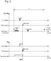
- a first coded signal such as a basic signal with a brewing code or a modulation of a pseudo-random sequence of noise from the unlocking device 2 to the electronic key 3.
- This coded basic signal can be transmitted after a predetermined time interval following the LF activation of the electronic key.
- transmitting the unlocking device it can be triggered a specific timer in the device clocked by the crystal resonator oscillator or at a higher frequency based on the local oscillator for example at 250 MHz.
- the electronic key receives this first basic signal and demodulates it by defining the time. Then, the electronic key generates a second coded signal, such as a coded response signal after a definite first transmission time T F determined since the initiation of the basic signal in the unlocking device.
- This first transmission time T F defined which can be of the order of 0.1 ms, is obtained by the delay following the reception of the basic signal and thanks to a local oscillator similar to that of the unlocking device.
- This coded response signal is received by the unlocking device.
- a processing is performed in time offset, that is to say after a lapse of time in the unlocking device to determine the flight times between the two entities and the first defined response time of the electronic key.
- the time delay is very accurate in the device and in the key and the basic signal and the coded response signal are transmitted at high speed, for example at 26 Mbits / s, it is easy to determine the actual distance between the electronic key. of the vehicle. In addition, it ensures a very high security to prevent the opening of the vehicle through intermediate relays of malicious people.
- the electronic key 3 can be automatically deactivated and remain in a rest mode.
- the control of the delay and the response code of the electronic key 3 can be done in the processing unit 25 to the processor of the access or unlocking device 2 delayed after the deactivation of the electronic key.
- a command to open the door the vehicle can be ordered later.
- the time To between the activation of the electronic key 3 and the opening of the vehicle door can be of the order of 1 ms.
- this coded basic signal can be transmitted after a specified time interval following the activation of the electronic key.
- an accurate timer is triggered in the device clocked by the crystal resonator oscillator or at a higher frequency on the basis of the local oscillator, for example at 250. MHz.
- the electronic key receives this coded basic signal and demodulates it by defining the time. Then, the electronic key generates a coded response signal after a definite first transmission time T F determined since the initiation of the basic signal Code in the unlocking device.
- This first transmission time T F defined which can be of the order of 0.1 ms, is obtained by the delay following the reception of the basic signal and thanks to a local oscillator similar to that of the unlocking device.
- This coded response signal is a scrambled coded signal with additional modulation on the received coded basic signal or an encrypted signal with a previously programmed or generated symmetric or asymmetric encryption key.
- the generation of this coded scrambled response signal is longer than that of the first variant of the access method.
- the modulation may be at 1 Mbps in the coded response signal which is at a frequency of eg 5.8 GHz.
- the duration T B of this coded scrambled response signal may be of the order of 0.25 ms.
- This coded scrambled response signal is received by the unlocking device in a given reception time window in the unlocking device.
- the device is arranged to receive in this time window or time slot, the scrambled response coded signal.
- the duration of this reception time window is equivalent to that T B of the scrambled response coded signal.
- processing is performed in the processing unit of the unlocking device.
- the coded response signal received from the electronic key is compared with the locally generated version based on the initial code. After that, there is a determination of the flight times between the two entities, as well as the first response time T F of the electronic key. Since the time delay is very accurate in the device and in the key and the basic signal and the coded response signal are transmitted at high speed, for example at 26 Mbits / s, it is easy to determine the actual distance between the electronic key. of the vehicle. This also guarantees access to the vehicle only to the electronic key near said vehicle for high security.
- the electronic key can be automatically deactivated to remain in a rest mode.
- An opening command of the vehicle door can be ordered later after the treatment in the processing unit.
- the time To between the activation of the electronic key and the opening of the vehicle door can be of the order of 10 ms.
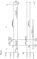
- the electronic key is activated by the low frequency signal LF transmitted by the unlocking device. After activation of the electronic key, it may be provided to transmit from the electronic key a continuous signal with a carrier frequency CW, which is for example of the order of 5.8 GHz.
- the unlocking device receives this carrier frequency signal, which will be used to calculate the frequency error of the electronic key, for example by a fast Fourier transform in the processing unit.
- the unlocking device then transmits a basic signal Code, which is a medium bit rate code signal of the order of 1 Mbit / s or a cabled or random code signal encrypted with a symmetrical or asymmetric key.
- This transmission of the basic signal is longer than the transmission of the basic signal of the first and second variants of the method, for example of the order of 1 ms.
- the distance determination is subsequently performed with less accuracy, but with reduced complexity of processing components.
- the electronic key receives this coded basic signal, demodulates it and decrypts it in order to parameterize the analysis performed in the processing unit of the electronic key. Since the two oscillators of the device and the key are not yet calibrated, the synchronization upon reception of the basic signal coded by the electronic key is still a fuzzy synchronization. Upon receipt of the signal CW (sent by the key), an oscillation frequency error calculation is performed in the processing unit of the unlocking device.
- a new transmission of a first coded answer 1 response signal is performed from the delayed unlocking device, that is to say after a determined time T R1 continued to the transmission of the basic signal with the brewing code.
- the first coded response signal is transmitted to the electronic key, this transmission conveying precise synchronization.
- the electronic key receives this first scrambled response signal of the unlocking device for example in a reception time window equivalent to the duration of the first coded response signal.
- a processing of the first scrambled response signal is performed in the processing unit of the electronic key.
- a calculation of a start time by a correlation of the first expected scrambled response signal (decrypted from the initial brewing code) is performed. This correlation makes it possible to precisely align the start of the transmission of the second response signal with the arrival of the first response.
- the dongle generates a second coded scrambled response signal (pseudo random), which is transmitted at the end of processing in the processing unit.
- the transmission of this second coded response signal is carried out with good synchronization and a high bit rate of, for example, 125 Mbps to the unlocking device.
- the unlocking device receives this second coded answer signal Response 2, which is scrambled (pseudo random), in a reception time window well synchronized by the unlocking device. Subsequently a correlation of the second coded response signal of the electronic key is performed in the processing unit of the deferred device, that is to say after a determined time at the end of the reception of the second coded response signal. scrambled (pseudo random). This correlation of the scrambled second coded response signal is performed according to an expected coding of the response of the electronic key. A calculation of the flight times of the signals between the device and the key and between the key and the device is still performed in the processing unit. A distance between the electronic key and the unlocking device can still be determined, in order to allow the opening of the vehicle, if the key is well recognized and that it is at a determined distance near the vehicle relative to a vehicle. distance threshold determined.
- this guarantees a high level of security. This makes it possible to determine any intermediate relay (thus additional transmission delay) used to attempt to open the vehicle without the knowledge of the holder of the electronic key. After recognition of the electronic key, the vehicle can be opened a lapse of time after the treatment in the processing unit of the device. The total duration T 0 since the activation of the electronic key until the complete processing of the information stored in the unlocking device can be of the order of 10 ms.
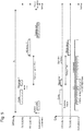
- the electronic key is activated by the low frequency signal LF transmitted by the unlocking device.
- the unlocking device transmits a basic signal Code, which is a medium bit rate code signal of the order of 1 Mbits / s or a ciphered or random code signal encrypted with a symmetrical or asymmetrical key.
- This transmission of the basic signal is longer than the transmission of the basic signal of the first and second variants of the method, for example of the order of 1 ms.
- the electronic key receives this coded basic signal, demodulates it and decrypts it. As the bit rate and therefore the bandwidth are reduced during this first transmission, the synchronization upon reception of the basic signal coded by the electronic key is still a fuzzy synchronization.
- the electronic key performs, in its processing unit, a frequency error calculation of the unlocking device with the electronic key on the basis of base signal with received patch code. After this processing, a frequency correction of the local oscillator of the key occurs.
- a transmission of a first coded answer 1 response signal is performed from the delayed unlocking device, that is to say after a determined time T R1 following the transmission of the basic signal with a brewing code.
- This first coded response signal is a pseudo-random PN noise code signal, which is very high speed, for example of the order of 125 Mbits / s.
- the first coded response signal is transmitted to the electronic key to have, after correlation in the electronic key, a precise synchronization. Storage of this received PN code signal is performed in a register of a memory of the electronic key. The electronic key receives this first PN response signal from the unlocking device in a well-defined reception time window.
- a correlation of the first response of the unlocking device with the PN sequence deduced from the initial brewing code is performed in the processing unit of the key.
- This correlation makes it possible to precisely define the transmission time of a second pseudo-random PN noise signal (which is very high speed, for example of the order of 125 Mbit / s), after a determined time since the transmission of the first coded response signal of the device to the transmission of the electronic key.
- This determined time takes into account in addition to the fixed time of flight time signals between the device and the key and between the key and the device.
- Precise synchronization is obtained at the moment of transmission of the second PN noise pseudo-random code response signal, which is at very high speed, for example of the order of 125 Mbits / s.
- the unlocking device receives this second pseudo-random PN noise code response signal in a well synchronized reception time window and stores in a first register of a memory the information of the second response of the electronic key.
- the reception time in the reception window of the device is equivalent to the duration of the second response signal of the electronic key.
- a correlation is made with the known PN code of the second response response 2 of the electronic key.
- a safe calculation of flight times is further determined to also determine the distance between the electronic key and the unlocking device to allow the vehicle to open after a lapse of time if the electronic key is recognized.
- the time To between the activation of the key and the opening of the vehicle door can be of the order of 10 ms.
- the duration of the second response, which is transmitted from the key to the vehicle may be longer than the first response, which is transmitted from the vehicle to the key.
- this makes it possible to have an increase in the correlation gain, and advantageously to reduce the transmission power of the key while maintaining a signal-to-noise ratio similar to that of the key car transmission, where it is easier to use. 'get power.
Landscapes
- Engineering & Computer Science (AREA)
- Computer Networks & Wireless Communication (AREA)
- General Physics & Mathematics (AREA)
- Physics & Mathematics (AREA)
- Remote Sensing (AREA)
- Radar, Positioning & Navigation (AREA)
- Computer Security & Cryptography (AREA)
- Signal Processing (AREA)
- Theoretical Computer Science (AREA)
- General Engineering & Computer Science (AREA)
- Computer Hardware Design (AREA)
- Mechanical Engineering (AREA)
- Software Systems (AREA)
- Computing Systems (AREA)
- Lock And Its Accessories (AREA)
- Selective Calling Equipment (AREA)
Priority Applications (5)
| Application Number | Priority Date | Filing Date | Title |
|---|---|---|---|
| EP16192418.8A EP3306576B1 (de) | 2016-10-05 | 2016-10-05 | Verfahren und system zum gesicherten zugang zu einem bestimmten raum mittels eines tragbaren objekts |
| CN201710887610.1A CN107920056B (zh) | 2016-10-05 | 2017-09-27 | 用于借助于可穿戴物体安全访问确定的空间的方法和系统 |
| JP2017192404A JP6663405B2 (ja) | 2016-10-05 | 2017-10-02 | 装着可能物体により決定空間へ安全にアクセスする方法及びシステム |
| US15/723,497 US10227059B2 (en) | 2016-10-05 | 2017-10-03 | Process and system for secure access to a determined space by means of a wearable object |
| HK18111781.0A HK1252473B (zh) | 2016-10-05 | 2018-09-13 | 用於借助於可穿戴物体安全访问确定的空间的方法和系统 |
Applications Claiming Priority (1)
| Application Number | Priority Date | Filing Date | Title |
|---|---|---|---|
| EP16192418.8A EP3306576B1 (de) | 2016-10-05 | 2016-10-05 | Verfahren und system zum gesicherten zugang zu einem bestimmten raum mittels eines tragbaren objekts |
Publications (2)
| Publication Number | Publication Date |
|---|---|
| EP3306576A1 true EP3306576A1 (de) | 2018-04-11 |
| EP3306576B1 EP3306576B1 (de) | 2023-03-15 |
Family
ID=57240806
Family Applications (1)
| Application Number | Title | Priority Date | Filing Date |
|---|---|---|---|
| EP16192418.8A Active EP3306576B1 (de) | 2016-10-05 | 2016-10-05 | Verfahren und system zum gesicherten zugang zu einem bestimmten raum mittels eines tragbaren objekts |
Country Status (4)
| Country | Link |
|---|---|
| US (1) | US10227059B2 (de) |
| EP (1) | EP3306576B1 (de) |
| JP (1) | JP6663405B2 (de) |
| CN (1) | CN107920056B (de) |
Families Citing this family (10)
| Publication number | Priority date | Publication date | Assignee | Title |
|---|---|---|---|---|
| FR3041459B1 (fr) * | 2015-09-18 | 2017-10-13 | Valeo Comfort & Driving Assistance | Procede de determination d'une distance entre un vehicule et un identifiant |
| DE102017201308B4 (de) * | 2017-01-27 | 2020-07-02 | Continental Automotive Gmbh | Verfahren zum Verifizieren eines vorgegebenen räumlichen Maximalabstands eines Funkschlüssels bezüglich eines Kraftfahrzeugs sowie Steuervorrichtung, Kraftfahrzeug und Funkschlüssel |
| DE102017120524A1 (de) * | 2017-04-28 | 2018-10-31 | Huf Hülsbeck & Fürst Gmbh & Co. Kg | Tragbarer ID-Geber für ein Authentifizierungssystem und Verfahren zum Betreiben eines Authentifizierungssystems |
| DE102017109293A1 (de) | 2017-04-28 | 2018-10-31 | Huf Hülsbeck & Fürst Gmbh & Co. Kg | Verfahren zum Betreiben eines Authentifizierungssystems und Authentifizierungssystem |
| US10089810B1 (en) * | 2017-12-01 | 2018-10-02 | OpenPath Security Inc. | Rolling code based proximity verification for entry access |
| CN110543231B (zh) * | 2018-05-28 | 2022-11-15 | Oppo广东移动通信有限公司 | 电子装置控制方法及相关设备 |
| EP3594911B1 (de) * | 2018-07-11 | 2023-04-19 | Aptiv Technologies Limited | Verfahren zur verhinderung von sicherheitslücken eines passiven fernbedienbaren schlüssellosen zugangssystems |
| GB2584848A (en) | 2019-06-17 | 2020-12-23 | Airbus Operations Ltd | Confirmation of tyre monitoring device status |
| CN114026901B (zh) * | 2019-07-30 | 2023-12-19 | 艾迈斯-欧司朗亚太私人有限公司 | 通过飞行时间认证邻近性 |
| GB2602009A (en) * | 2020-12-15 | 2022-06-22 | Airbus Operations Ltd | Tyre pressure monitoring devices enforcing range limitation on communication |
Citations (8)
| Publication number | Priority date | Publication date | Assignee | Title |
|---|---|---|---|---|
| EP0673003B1 (de) | 1994-03-17 | 1998-10-07 | Siemens Aktiengesellschaft | Schlüssellose Zugangskontrolleinrichtung |
| WO2001025060A2 (en) * | 1999-10-01 | 2001-04-12 | Siemens Automotive Corporation | Relay attach detection of a secure vehicle command communication |
| EP1152108A2 (de) * | 2000-05-03 | 2001-11-07 | Delphi Technologies, Inc. | Handfreies Zugangssystem für Kraftfahrzeuge |
| US6538560B1 (en) | 1997-07-05 | 2003-03-25 | Leopold Kostal Gmbh & Co. | Keyless device for controlling access to automobiles and keyless method for checking access authorization |
| US20090006032A1 (en) * | 2005-01-11 | 2009-01-01 | Koninklijke Philips Electronics, N.V. | Time of Flight |
| US20100265035A1 (en) * | 2009-04-16 | 2010-10-21 | Boris Ziller | Process to secure keyless entry communications for motor vehicles |
| EP2796988B1 (de) | 2013-04-26 | 2015-09-16 | EM Microelectronic-Marin SA | Zufallszahlengenerator |
| US20160112846A1 (en) * | 2013-05-31 | 2016-04-21 | Jaguar Land Rover Limited | Position-Based Limited-Response Mode Operation in a Vehicle Communication System |
Family Cites Families (27)
| Publication number | Priority date | Publication date | Assignee | Title |
|---|---|---|---|---|
| JP2937673B2 (ja) * | 1993-01-25 | 1999-08-23 | 株式会社東芝 | 通信装置 |
| BR9913440B1 (pt) * | 1998-09-01 | 2008-11-18 | processo para a realizaÇço de um controle de autorizaÇço de acesso sem chave e equipamento de controle de autorizaÇço de acesso sem chave. | |
| JP3692843B2 (ja) * | 1999-07-15 | 2005-09-07 | 株式会社デンソー | 自動車ドアロック制御装置 |
| US6535161B1 (en) * | 2000-11-28 | 2003-03-18 | Mcewan Technologies, Llc | Loop powered radar rangefinder |
| EP1563570A1 (de) * | 2002-11-07 | 2005-08-17 | Fractus, S.A. | Integriertes schaltungsgehäuse mit miniaturantenne |
| WO2005091889A2 (en) * | 2004-03-05 | 2005-10-06 | Seknion, Inc. | Method and apparatus for improving the efficiency and accuracy of rfid systems |
| GB0415219D0 (en) * | 2004-07-07 | 2004-08-11 | Koninkl Philips Electronics Nv | Improvements in or relating to time-of-flight ranging systems |
| US7466219B2 (en) * | 2004-10-19 | 2008-12-16 | Sanyo Electric Co., Ltd. | Communication device and distance calculation system |
| US7988055B2 (en) * | 2005-01-20 | 2011-08-02 | Wright State University | Uncontrolled passive radio frequency identification tag and system with 3-D positioning |
| US7944340B1 (en) * | 2006-09-28 | 2011-05-17 | Lear Corporation | System and method for two-way remote activation with adaptive protocol |
| JP2009166550A (ja) * | 2008-01-11 | 2009-07-30 | Mitsubishi Electric Corp | 車載機器遠隔制御システムおよび車載機器遠隔制御方法 |
| US8204031B2 (en) * | 2008-09-24 | 2012-06-19 | Rockstar Bidco, LP | Duplexer/multiplexer having filters that include at least one band reject filter |
| EP2204669A1 (de) * | 2008-12-30 | 2010-07-07 | Atmel Automotive GmbH | System, Verfahren und Schaltung zur Entfernungsmessung zwischen zwei Knoten eines Funknetzes |
| JP5405951B2 (ja) * | 2009-09-15 | 2014-02-05 | 株式会社東海理化電機製作所 | 電子キーシステム |
| US8723720B2 (en) * | 2011-05-03 | 2014-05-13 | Harris Corporation | Wireless location detection and/or tracking device and associated methods |
| CN103366745B (zh) * | 2012-03-29 | 2016-01-20 | 三星电子(中国)研发中心 | 基于语音识别保护终端设备的方法及其终端设备 |
| MX2014015223A (es) * | 2012-06-18 | 2015-03-19 | Master Lock Co | Sistema de deteccion de identificacion de radiofrecuencia. |
| US8826415B2 (en) * | 2012-09-04 | 2014-09-02 | Apple Inc. | Automated device access |
| KR20150132459A (ko) * | 2013-03-15 | 2015-11-25 | 키사, 아이엔씨. | Ehf 보안 통신 장치 |
| US9709672B2 (en) * | 2013-08-16 | 2017-07-18 | Drnc Holdings, Inc. | Method and system for identifying and finding a range of an object |
| JP6354165B2 (ja) * | 2014-01-15 | 2018-07-11 | 株式会社デンソー | 制御システム |
| JP6372688B2 (ja) * | 2014-07-28 | 2018-08-15 | 株式会社デンソー | 車両用通信システム |
| US10177846B2 (en) * | 2014-12-01 | 2019-01-08 | Infineon Technologies Ag | Transceiver device, access control devices, a transmitter device and a receiver device |
| CN104494563B (zh) * | 2014-12-24 | 2018-04-13 | 马瑞利汽车电子(广州)有限公司 | 一种基于通讯总线的汽车无钥匙进入与启动的系统和方法 |
| US9894613B2 (en) * | 2015-07-22 | 2018-02-13 | GM Global Technology Operations LLC | Time of flight based passive entry/passive start system |
| US10440574B2 (en) * | 2016-06-12 | 2019-10-08 | Apple Inc. | Unlocking a device |
| US10634776B2 (en) * | 2016-09-23 | 2020-04-28 | Apple Inc. | Time of flight estimation using an asymmetric scheme |
-
2016
- 2016-10-05 EP EP16192418.8A patent/EP3306576B1/de active Active
-
2017
- 2017-09-27 CN CN201710887610.1A patent/CN107920056B/zh active Active
- 2017-10-02 JP JP2017192404A patent/JP6663405B2/ja active Active
- 2017-10-03 US US15/723,497 patent/US10227059B2/en active Active
Patent Citations (8)
| Publication number | Priority date | Publication date | Assignee | Title |
|---|---|---|---|---|
| EP0673003B1 (de) | 1994-03-17 | 1998-10-07 | Siemens Aktiengesellschaft | Schlüssellose Zugangskontrolleinrichtung |
| US6538560B1 (en) | 1997-07-05 | 2003-03-25 | Leopold Kostal Gmbh & Co. | Keyless device for controlling access to automobiles and keyless method for checking access authorization |
| WO2001025060A2 (en) * | 1999-10-01 | 2001-04-12 | Siemens Automotive Corporation | Relay attach detection of a secure vehicle command communication |
| EP1152108A2 (de) * | 2000-05-03 | 2001-11-07 | Delphi Technologies, Inc. | Handfreies Zugangssystem für Kraftfahrzeuge |
| US20090006032A1 (en) * | 2005-01-11 | 2009-01-01 | Koninklijke Philips Electronics, N.V. | Time of Flight |
| US20100265035A1 (en) * | 2009-04-16 | 2010-10-21 | Boris Ziller | Process to secure keyless entry communications for motor vehicles |
| EP2796988B1 (de) | 2013-04-26 | 2015-09-16 | EM Microelectronic-Marin SA | Zufallszahlengenerator |
| US20160112846A1 (en) * | 2013-05-31 | 2016-04-21 | Jaguar Land Rover Limited | Position-Based Limited-Response Mode Operation in a Vehicle Communication System |
Also Published As
| Publication number | Publication date |
|---|---|
| CN107920056A (zh) | 2018-04-17 |
| US10227059B2 (en) | 2019-03-12 |
| HK1252473A1 (zh) | 2019-05-24 |
| US20180093642A1 (en) | 2018-04-05 |
| JP6663405B2 (ja) | 2020-03-11 |
| JP2018059395A (ja) | 2018-04-12 |
| EP3306576B1 (de) | 2023-03-15 |
| CN107920056B (zh) | 2020-09-08 |
Similar Documents
| Publication | Publication Date | Title |
|---|---|---|
| EP3306576B1 (de) | Verfahren und system zum gesicherten zugang zu einem bestimmten raum mittels eines tragbaren objekts | |
| EP2766883A1 (de) | Fernsteuerungssystem und verfahren zur automatischen verriegelung-und/oder entriegelung mindestens einer beweglichen platte eines kraftfahrzeugs und/oder zum starten eines kraftfahrzeugmotors mithilfe des fernsteuerungssystems | |
| EP1001117B1 (de) | System zum Sichern einer bidirektionellen Datenübertragung für den Zugang zu einem abgeschlossenen Raum, insbesondere für den Zugang zu einem Fahrzeug | |
| EP3450669B1 (de) | Modulares gehäuse und verfahren zum ver-/entriegeln von mindestens zwei öffnungselementen eines solchen gehäuses | |
| FR3055278A1 (fr) | Vehicule sans pilote, et procede de deverouillage simultane d'au moins deux ouvrants d'un tel vehicule | |
| FR3084495A1 (fr) | Système passif d’entrée sans clé | |
| FR3135738A1 (fr) | Procédé d’activation d’une fonction véhicule et dispositif d’activation associé | |
| EP1152109B1 (de) | Handfreies Zugangs- und/oder Startsystem für Kraftfahrzeuge | |
| WO2017046388A1 (fr) | Procédé de commande d'une fonctionnalité d'un véhicule au moyen d'un terminal utilisateur et système de commande associé | |
| EP1058214A1 (de) | Verfahren zur bidirektionalen Datenübertragung und System zur Ausführung derselben | |
| EP1429300A1 (de) | Verfahren zur Lokalisierung eines tragbaren Elements in einem handfreien Sicherungssystem, und entsprechendes handfreies Sicherungssystem | |
| EP3301838B1 (de) | Verfahren und system zur bestimmung der entfernung zwischen einem tragbaren objekt und einer basisstation | |
| EP1152108B1 (de) | Handfreies Zugangssystem für Kraftfahrzeuge | |
| FR2797727A1 (fr) | Dispositif d'identification d'habilitation et de declenchement/mise en disponibilite d'une action, notamment pour vehicule automobile | |
| EP1378865B1 (de) | Verfahren zur Zugangskontrolle eines bestimmten Raumes mit einem personalisierten tragbaren Gerät, und personalisiertes tragbares Gerät zum Durchführen des Verfahrens | |
| EP1378864A1 (de) | Verfahren zur Zugangskontrolle eines bestimmten Raumes mit einem personalisierten tragbaren Gerät, und personalisiertes tragbares Gerät zum Durchführen des Verfahrens | |
| EP1152107B1 (de) | Gegen Betrug gerichtetes System für den freihändigen Zugang zu einem Automobil | |
| WO1999066451A1 (fr) | Objet portatif a communication sans contact suivant deux voies de communication, inductive et hertzienne | |
| FR2891519A1 (fr) | Systeme d'ajustement d'informations d'etat d'un vehicule entre au moins deux transmetteurs d'identification | |
| EP1061211B1 (de) | Verfahren zur Sicherung einer bidirektionellen Datenübertragung mit einer Kennzeichnung und System zu dessen Durchführung | |
| EP1178169B1 (de) | Gegen Betrug gerichtetes Fernsteuerungsverfahren für Fahrzeuge und System zur Durchführung des Verfahrens | |
| FR3161828A1 (fr) | Procédé de détection de présence d’un transpondeur NFC | |
| FR2823167A1 (fr) | Dispositif pour commander un dispositif de securite | |
| EP1261182B1 (de) | Empfänger für frequenzmodulierte Signale mit digitalen Demodulator | |
| EP1277633A1 (de) | Elektrische Identifizierungsvorrichtung |
Legal Events
| Date | Code | Title | Description |
|---|---|---|---|
| PUAI | Public reference made under article 153(3) epc to a published international application that has entered the european phase |
Free format text: ORIGINAL CODE: 0009012 |
|
| STAA | Information on the status of an ep patent application or granted ep patent |
Free format text: STATUS: THE APPLICATION HAS BEEN PUBLISHED |
|
| AK | Designated contracting states |
Kind code of ref document: A1 Designated state(s): AL AT BE BG CH CY CZ DE DK EE ES FI FR GB GR HR HU IE IS IT LI LT LU LV MC MK MT NL NO PL PT RO RS SE SI SK SM TR |
|
| AX | Request for extension of the european patent |
Extension state: BA ME |
|
| STAA | Information on the status of an ep patent application or granted ep patent |
Free format text: STATUS: REQUEST FOR EXAMINATION WAS MADE |
|
| 17P | Request for examination filed |
Effective date: 20181011 |
|
| RBV | Designated contracting states (corrected) |
Designated state(s): AL AT BE BG CH CY CZ DE DK EE ES FI FR GB GR HR HU IE IS IT LI LT LU LV MC MK MT NL NO PL PT RO RS SE SI SK SM TR |
|
| STAA | Information on the status of an ep patent application or granted ep patent |
Free format text: STATUS: EXAMINATION IS IN PROGRESS |
|
| 17Q | First examination report despatched |
Effective date: 20210621 |
|
| GRAP | Despatch of communication of intention to grant a patent |
Free format text: ORIGINAL CODE: EPIDOSNIGR1 |
|
| STAA | Information on the status of an ep patent application or granted ep patent |
Free format text: STATUS: GRANT OF PATENT IS INTENDED |
|
| INTG | Intention to grant announced |
Effective date: 20221221 |
|
| GRAS | Grant fee paid |
Free format text: ORIGINAL CODE: EPIDOSNIGR3 |
|
| GRAA | (expected) grant |
Free format text: ORIGINAL CODE: 0009210 |
|
| STAA | Information on the status of an ep patent application or granted ep patent |
Free format text: STATUS: THE PATENT HAS BEEN GRANTED |
|
| AK | Designated contracting states |
Kind code of ref document: B1 Designated state(s): AL AT BE BG CH CY CZ DE DK EE ES FI FR GB GR HR HU IE IS IT LI LT LU LV MC MK MT NL NO PL PT RO RS SE SI SK SM TR |
|
| REG | Reference to a national code |
Ref country code: CH Ref legal event code: EP Ref country code: GB Ref legal event code: FG4D Free format text: NOT ENGLISH |
|
| REG | Reference to a national code |
Ref country code: DE Ref legal event code: R096 Ref document number: 602016078286 Country of ref document: DE |
|
| REG | Reference to a national code |
Ref country code: IE Ref legal event code: FG4D Free format text: LANGUAGE OF EP DOCUMENT: FRENCH |
|
| REG | Reference to a national code |
Ref country code: AT Ref legal event code: REF Ref document number: 1554446 Country of ref document: AT Kind code of ref document: T Effective date: 20230415 |
|
| REG | Reference to a national code |
Ref country code: LT Ref legal event code: MG9D |
|
| REG | Reference to a national code |
Ref country code: NL Ref legal event code: MP Effective date: 20230315 |
|
| P01 | Opt-out of the competence of the unified patent court (upc) registered |
Effective date: 20230615 |
|
| PG25 | Lapsed in a contracting state [announced via postgrant information from national office to epo] |
Ref country code: RS Free format text: LAPSE BECAUSE OF FAILURE TO SUBMIT A TRANSLATION OF THE DESCRIPTION OR TO PAY THE FEE WITHIN THE PRESCRIBED TIME-LIMIT Effective date: 20230315 Ref country code: NO Free format text: LAPSE BECAUSE OF FAILURE TO SUBMIT A TRANSLATION OF THE DESCRIPTION OR TO PAY THE FEE WITHIN THE PRESCRIBED TIME-LIMIT Effective date: 20230615 Ref country code: LV Free format text: LAPSE BECAUSE OF FAILURE TO SUBMIT A TRANSLATION OF THE DESCRIPTION OR TO PAY THE FEE WITHIN THE PRESCRIBED TIME-LIMIT Effective date: 20230315 Ref country code: LT Free format text: LAPSE BECAUSE OF FAILURE TO SUBMIT A TRANSLATION OF THE DESCRIPTION OR TO PAY THE FEE WITHIN THE PRESCRIBED TIME-LIMIT Effective date: 20230315 Ref country code: HR Free format text: LAPSE BECAUSE OF FAILURE TO SUBMIT A TRANSLATION OF THE DESCRIPTION OR TO PAY THE FEE WITHIN THE PRESCRIBED TIME-LIMIT Effective date: 20230315 |
|
| REG | Reference to a national code |
Ref country code: AT Ref legal event code: MK05 Ref document number: 1554446 Country of ref document: AT Kind code of ref document: T Effective date: 20230315 |
|
| PG25 | Lapsed in a contracting state [announced via postgrant information from national office to epo] |
Ref country code: SE Free format text: LAPSE BECAUSE OF FAILURE TO SUBMIT A TRANSLATION OF THE DESCRIPTION OR TO PAY THE FEE WITHIN THE PRESCRIBED TIME-LIMIT Effective date: 20230315 Ref country code: NL Free format text: LAPSE BECAUSE OF FAILURE TO SUBMIT A TRANSLATION OF THE DESCRIPTION OR TO PAY THE FEE WITHIN THE PRESCRIBED TIME-LIMIT Effective date: 20230315 Ref country code: GR Free format text: LAPSE BECAUSE OF FAILURE TO SUBMIT A TRANSLATION OF THE DESCRIPTION OR TO PAY THE FEE WITHIN THE PRESCRIBED TIME-LIMIT Effective date: 20230616 Ref country code: FI Free format text: LAPSE BECAUSE OF FAILURE TO SUBMIT A TRANSLATION OF THE DESCRIPTION OR TO PAY THE FEE WITHIN THE PRESCRIBED TIME-LIMIT Effective date: 20230315 |
|
| PG25 | Lapsed in a contracting state [announced via postgrant information from national office to epo] |
Ref country code: SM Free format text: LAPSE BECAUSE OF FAILURE TO SUBMIT A TRANSLATION OF THE DESCRIPTION OR TO PAY THE FEE WITHIN THE PRESCRIBED TIME-LIMIT Effective date: 20230315 Ref country code: RO Free format text: LAPSE BECAUSE OF FAILURE TO SUBMIT A TRANSLATION OF THE DESCRIPTION OR TO PAY THE FEE WITHIN THE PRESCRIBED TIME-LIMIT Effective date: 20230315 Ref country code: PT Free format text: LAPSE BECAUSE OF FAILURE TO SUBMIT A TRANSLATION OF THE DESCRIPTION OR TO PAY THE FEE WITHIN THE PRESCRIBED TIME-LIMIT Effective date: 20230717 Ref country code: ES Free format text: LAPSE BECAUSE OF FAILURE TO SUBMIT A TRANSLATION OF THE DESCRIPTION OR TO PAY THE FEE WITHIN THE PRESCRIBED TIME-LIMIT Effective date: 20230315 Ref country code: EE Free format text: LAPSE BECAUSE OF FAILURE TO SUBMIT A TRANSLATION OF THE DESCRIPTION OR TO PAY THE FEE WITHIN THE PRESCRIBED TIME-LIMIT Effective date: 20230315 Ref country code: CZ Free format text: LAPSE BECAUSE OF FAILURE TO SUBMIT A TRANSLATION OF THE DESCRIPTION OR TO PAY THE FEE WITHIN THE PRESCRIBED TIME-LIMIT Effective date: 20230315 Ref country code: AT Free format text: LAPSE BECAUSE OF FAILURE TO SUBMIT A TRANSLATION OF THE DESCRIPTION OR TO PAY THE FEE WITHIN THE PRESCRIBED TIME-LIMIT Effective date: 20230315 |
|
| PG25 | Lapsed in a contracting state [announced via postgrant information from national office to epo] |
Ref country code: SK Free format text: LAPSE BECAUSE OF FAILURE TO SUBMIT A TRANSLATION OF THE DESCRIPTION OR TO PAY THE FEE WITHIN THE PRESCRIBED TIME-LIMIT Effective date: 20230315 Ref country code: PL Free format text: LAPSE BECAUSE OF FAILURE TO SUBMIT A TRANSLATION OF THE DESCRIPTION OR TO PAY THE FEE WITHIN THE PRESCRIBED TIME-LIMIT Effective date: 20230315 Ref country code: IS Free format text: LAPSE BECAUSE OF FAILURE TO SUBMIT A TRANSLATION OF THE DESCRIPTION OR TO PAY THE FEE WITHIN THE PRESCRIBED TIME-LIMIT Effective date: 20230715 |
|
| REG | Reference to a national code |
Ref country code: DE Ref legal event code: R097 Ref document number: 602016078286 Country of ref document: DE |
|
| PLBE | No opposition filed within time limit |
Free format text: ORIGINAL CODE: 0009261 |
|
| STAA | Information on the status of an ep patent application or granted ep patent |
Free format text: STATUS: NO OPPOSITION FILED WITHIN TIME LIMIT |
|
| PG25 | Lapsed in a contracting state [announced via postgrant information from national office to epo] |
Ref country code: SI Free format text: LAPSE BECAUSE OF FAILURE TO SUBMIT A TRANSLATION OF THE DESCRIPTION OR TO PAY THE FEE WITHIN THE PRESCRIBED TIME-LIMIT Effective date: 20230315 Ref country code: DK Free format text: LAPSE BECAUSE OF FAILURE TO SUBMIT A TRANSLATION OF THE DESCRIPTION OR TO PAY THE FEE WITHIN THE PRESCRIBED TIME-LIMIT Effective date: 20230315 |
|
| 26N | No opposition filed |
Effective date: 20231218 |
|
| PG25 | Lapsed in a contracting state [announced via postgrant information from national office to epo] |
Ref country code: IT Free format text: LAPSE BECAUSE OF FAILURE TO SUBMIT A TRANSLATION OF THE DESCRIPTION OR TO PAY THE FEE WITHIN THE PRESCRIBED TIME-LIMIT Effective date: 20230315 Ref country code: MC Free format text: LAPSE BECAUSE OF FAILURE TO SUBMIT A TRANSLATION OF THE DESCRIPTION OR TO PAY THE FEE WITHIN THE PRESCRIBED TIME-LIMIT Effective date: 20230315 |
|
| REG | Reference to a national code |
Ref country code: BE Ref legal event code: MM Effective date: 20231031 |
|
| PG25 | Lapsed in a contracting state [announced via postgrant information from national office to epo] |
Ref country code: LU Free format text: LAPSE BECAUSE OF NON-PAYMENT OF DUE FEES Effective date: 20231005 |
|
| GBPC | Gb: european patent ceased through non-payment of renewal fee |
Effective date: 20231005 |
|
| PG25 | Lapsed in a contracting state [announced via postgrant information from national office to epo] |
Ref country code: LU Free format text: LAPSE BECAUSE OF NON-PAYMENT OF DUE FEES Effective date: 20231005 |
|
| PG25 | Lapsed in a contracting state [announced via postgrant information from national office to epo] |
Ref country code: GB Free format text: LAPSE BECAUSE OF NON-PAYMENT OF DUE FEES Effective date: 20231005 |
|
| PG25 | Lapsed in a contracting state [announced via postgrant information from national office to epo] |
Ref country code: GB Free format text: LAPSE BECAUSE OF NON-PAYMENT OF DUE FEES Effective date: 20231005 |
|
| PG25 | Lapsed in a contracting state [announced via postgrant information from national office to epo] |
Ref country code: BE Free format text: LAPSE BECAUSE OF NON-PAYMENT OF DUE FEES Effective date: 20231031 |
|
| PG25 | Lapsed in a contracting state [announced via postgrant information from national office to epo] |
Ref country code: IE Free format text: LAPSE BECAUSE OF NON-PAYMENT OF DUE FEES Effective date: 20231005 |
|
| PG25 | Lapsed in a contracting state [announced via postgrant information from national office to epo] |
Ref country code: IE Free format text: LAPSE BECAUSE OF NON-PAYMENT OF DUE FEES Effective date: 20231005 |
|
| PG25 | Lapsed in a contracting state [announced via postgrant information from national office to epo] |
Ref country code: BG Free format text: LAPSE BECAUSE OF FAILURE TO SUBMIT A TRANSLATION OF THE DESCRIPTION OR TO PAY THE FEE WITHIN THE PRESCRIBED TIME-LIMIT Effective date: 20230315 |
|
| PG25 | Lapsed in a contracting state [announced via postgrant information from national office to epo] |
Ref country code: BG Free format text: LAPSE BECAUSE OF FAILURE TO SUBMIT A TRANSLATION OF THE DESCRIPTION OR TO PAY THE FEE WITHIN THE PRESCRIBED TIME-LIMIT Effective date: 20230315 |
|
| PG25 | Lapsed in a contracting state [announced via postgrant information from national office to epo] |
Ref country code: CY Free format text: LAPSE BECAUSE OF FAILURE TO SUBMIT A TRANSLATION OF THE DESCRIPTION OR TO PAY THE FEE WITHIN THE PRESCRIBED TIME-LIMIT; INVALID AB INITIO Effective date: 20161005 |
|
| PG25 | Lapsed in a contracting state [announced via postgrant information from national office to epo] |
Ref country code: HU Free format text: LAPSE BECAUSE OF FAILURE TO SUBMIT A TRANSLATION OF THE DESCRIPTION OR TO PAY THE FEE WITHIN THE PRESCRIBED TIME-LIMIT; INVALID AB INITIO Effective date: 20161005 |
|
| PGFP | Annual fee paid to national office [announced via postgrant information from national office to epo] |
Ref country code: FR Payment date: 20250924 Year of fee payment: 10 |
|
| REG | Reference to a national code |
Ref country code: CH Ref legal event code: U11 Free format text: ST27 STATUS EVENT CODE: U-0-0-U10-U11 (AS PROVIDED BY THE NATIONAL OFFICE) Effective date: 20251101 |
|
| PG25 | Lapsed in a contracting state [announced via postgrant information from national office to epo] |
Ref country code: TR Free format text: LAPSE BECAUSE OF FAILURE TO SUBMIT A TRANSLATION OF THE DESCRIPTION OR TO PAY THE FEE WITHIN THE PRESCRIBED TIME-LIMIT Effective date: 20230315 |
|
| PGFP | Annual fee paid to national office [announced via postgrant information from national office to epo] |
Ref country code: DE Payment date: 20250923 Year of fee payment: 10 |
|
| PGFP | Annual fee paid to national office [announced via postgrant information from national office to epo] |
Ref country code: CH Payment date: 20251101 Year of fee payment: 10 |