EP3306590A1 - Fahrerassistenzsystem und -verfahren für ein motorfahrzeug - Google Patents
Fahrerassistenzsystem und -verfahren für ein motorfahrzeug Download PDFInfo
- Publication number
- EP3306590A1 EP3306590A1 EP16192921.1A EP16192921A EP3306590A1 EP 3306590 A1 EP3306590 A1 EP 3306590A1 EP 16192921 A EP16192921 A EP 16192921A EP 3306590 A1 EP3306590 A1 EP 3306590A1
- Authority
- EP
- European Patent Office
- Prior art keywords
- driver assistance
- assistance system
- data
- risk level
- input source
- Prior art date
- Legal status (The legal status is an assumption and is not a legal conclusion. Google has not performed a legal analysis and makes no representation as to the accuracy of the status listed.)
- Withdrawn
Links
Images
Classifications
-
- G—PHYSICS
- G08—SIGNALLING
- G08G—TRAFFIC CONTROL SYSTEMS
- G08G1/00—Traffic control systems for road vehicles
- G08G1/16—Anti-collision systems
- G08G1/165—Anti-collision systems for passive traffic, e.g. including static obstacles, trees
-
- G—PHYSICS
- G08—SIGNALLING
- G08G—TRAFFIC CONTROL SYSTEMS
- G08G1/00—Traffic control systems for road vehicles
- G08G1/16—Anti-collision systems
- G08G1/166—Anti-collision systems for active traffic, e.g. moving vehicles, pedestrians, bikes
Definitions
- the invention relates to a driver assistance system for a motor vehicle, comprising an imaging apparatus adapted to capture images of the surrounding of a motor vehicle, and a processing device adapted to perform image processing on the captured images and to control a driver assistance device based on the result of said image processing, wherein said processing device comprises a risk assessment estimator adapted to estimate a traffic risk level.
- Assessing the risk level can be beneficial for informing the driver so that the driver can adapt to an adequate alertness level.
- the functionality is beneficial in different ways for the range of manually controlled to semi-autonomous to fully autonomous vehicles.
- US 7,672,764 B2 discloses a driver assistance system including various sensors for recording driver's conditions and vehicle operations by a driver.
- the driver's conditions in combination with the vehicle operations are used to determine a risky situation of the vehicle based inter alia on an averaged driver's condition.
- the problem underlying the present invention is to provide a driver assistance system with improved traffic risk level estimation.
- the invention describes a driver assistance system where the risk assessment estimator estimates the traffic risk level on the basis of input source data from at least one input source including data captured by the imaging apparatus.
- the image data captured by the imaging apparatus contains valuable information in addition to sensor data from other vehicle sensors used in the prior art.
- traffic risk level refers to the amount of alertness required by the driver.
- the traffic risk level would be low when driving on an empty highway where no threats are near.
- a risky situation can for example be a situation where it is common for pedestrians to be near the road and/or where the speed of the ego vehicle is relatively high given the regulations of the current road.
- the appearance of the scene surrounding the motor vehicle extracted from captured images is used by said risk assessment estimator.
- scene refers to the landscape or background scenery, as opposed to detected objects like other vehicles, pedestrians, cyclists, animals etc.
- the environment of the vehicle may preferably be classifiable by the risk assessment estimator into one of city environment, highway environment, rural road environment.
- the risk assessment estimator considers the whole image in the determination of said traffic risk level.
- This holistic approach is advantageous over prior arts systems detecting and analyzing objects in the images, only, which form only small parts of the whole image.
- the considering of the whole image makes use of the complete image information contained in the image, where valuable information can also be contained in image parts not forming discrete objects like pedestrians, other vehicles, pavement, cross walk signs, bus stops etc.
- the risk assessment estimator considers each pixel of a captured image as a separate input source in the determination of said traffic risk level. Through the analysis of the captured images on an individual pixel level, maximum information can be used in the determination of the traffic risk level, avoiding any inaccuracies originating from averaging of the image over multipixel areas.
- the risk assessment estimator is trained by using a learning system, in particular a deep learning system, like a deep neural network.
- the network is preferably directly connected to each pixel of the captured images, and to other sensors used as input sources for said traffic risk level estimation.
- the learning system is preferably trained using training data rated by a plurality of persons with respect to the estimated traffic risk level. That is, each person rates the estimated traffic risk level of each training image according to his best evaluation, and for example the average of all ratings is taken as the true traffic risk level.
- the learning system could automatically learn to recognize aggressive driving, pedestrians (zebra) crossings, school areas, etc.
- the classifier could be trained by using publically available databases of accidents, containing corresponding GPS positions, and recording data at those locations. The classifier can then learn to recognize environments that look similar to actual environments where real accidents happen.
- the use of a plurality of input sources for the risk assessment estimator is desirable.
- a first category of preferred input sources provide ego vehicle data, in particular ego vehicle dynamics data, as input source data.
- input sources falling under this category are acceleration sensors, yaw sensor, roll sensor, pitch sensor, speed sensor, braking sensor, steering wheel angle sensor.
- a second category of preferred input sources provide data of other objects in the environment of the motor vehicle, in particular other object's dynamics data.
- Other (discrete) objects may for example be moving objects like other vehicles, pedestrians, bicyclists, large animals. Immovable objects like traffic signs, poles, buildings, trees etc. are also possible.
- Possible examples of input sources falling under this category are the imaging apparatus, a radar apparatus, a LIDAR apparatus, a backward looking camera. Also, it can be preferable to use a data memory or storing information about detected other objects as an input source.
- input source data comprising: speed limits obtained by sign recognition or a satellite navigation receiver; biometric information; road conditions; ambient conditions, like ambient temperature or ambient humidity; stored data of previous hazard areas or conditions; location of crosswalks obtained by image recognition or a satellite navigation receiver.
- the driver assistance system comprises a risk level indicator adapted to indicate an estimated risk level to the driver.
- a risk level indicator adapted to indicate an estimated risk level to the driver.
- one or more diodes could be used to indicate the risk level to the driver via color coding, e.g. covering the color spectrum between green (low risk level) to yellow (middle risk level) to red (high risk level).
- the estimated risk level may preferably be used for requesting safety-relevant actions by the driver depending on said estimated risk level. For example, at a first (lower) risk level, the driver could be requested to have his hands on the driving wheel, while at a second (higher) risk level, the driver could be requested to have his eyes on the road.
- the estimated risk levels may be used by a corresponding driver assistance device.
- information could be downloaded from the cloud during driving, e.g. traffic jam data, using driving dynamics of other vehicles (similar to electronic maps available in the internet), or average driver aggressiveness which may vary from region to region and from time to time of the day.
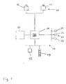
- the driver assistance system 10 is mounted in a motor vehicle and comprises an imaging apparatus 11 for capturing images of a region surrounding the motor vehicle, for example a region in front of the motor vehicle.
- the imaging apparatus 11 comprises one or more optical imaging devices 12, in particular cameras, preferably operating in the visible and/or infrared wavelength range, where infrared covers near IR with wavelengths below 5 microns and/or far IR with wavelengths beyond 5 microns.
- the imaging apparatus 11 comprises a plurality imaging devices 12 in particular forming a stereo imaging apparatus 11. In other embodiments only one imaging device 12 forming a mono imaging apparatus 11 can be used.
- the imaging apparatus 11 is coupled to a data processing device 14 adapted to process the image data received from the imaging apparatus 11.
- the data processing device 14 is preferably a digital device which is programmed or programmable and preferably comprises a microprocessor, microcontroller a digital signal processor (DSP), and/or a microprocessor part in a System-On-Chip (SoC) device, and preferably has access to, or comprises, a data memory 25.
- DSP digital signal processor
- SoC System-On-Chip
- the data processing device 14 may comprise a dedicated hardware device, like a Field Programmable Gate Array (FPGA) or an Application Specific Integrated Circuit (ASIC), or an FPGA and/or ASIC part in a System-On-Chip (SoC) device, for performing certain functions, for example controlling the capture of images by the imaging apparatus 11, receiving the electrical signal containing the image information from the imaging apparatus 11, rectifying or warping pairs of left/right images into alignment and/or creating disparity or depth images.
- the data processing device 14, or part of its functions can be realized by a System-On-Chip (SoC) device comprising, for example, FPGA, DSP, ARM and/or microprocessor functionality.
- SoC System-On-Chip
- the data processing device 14 and the memory device 25 are preferably realised in an on-board electronic control unit (ECU) and may be connected to the imaging apparatus 11 via a separate cable or a vehicle data bus.
- ECU electronice control unit
- the ECU and one or more of the imaging devices 12 can be integrated into a single unit, where a one box solution including the ECU and all imaging devices 12 can be preferred. All steps from imaging, image processing to possible activation or control of driver assistance device 18 are performed automatically and continuously during driving in real time.
- Image and data processing carried out in the processing device 14 advantageously comprises identifying and preferably also classifying possible objects (object candidates) in front of the motor vehicle, such as pedestrians, other vehicles, bicyclists and/or large animals, tracking over time the position of objects or object candidates identified in the captured images, and activating or controlling at least one driver assistance device 18 depending on an estimation performed with respect to a tracked object, for example on an estimated collision probability.
- the driver assistance device 18 may in particular comprise a display device to display information relating to a detected object.
- the invention is not limited to a display device.
- the driver assistance device 18 may in addition or alternatively comprise a warning device adapted to provide a collision warning to the driver by suitable optical, acoustical and/or haptic warning signals; one or more restraint systems such as occupant airbags or safety belt tensioners, pedestrian airbags, hood lifters and the like; and/or dynamic vehicle control systems such as braking or steering control devices.
- Information about detected objects may be stored in said data memory 25.
- the processing device 14 has access, for example via a vehicle data bus, to data from vehicle sensors 20 (21, 22, 23, ...) other than the imaging apparatus 12, which are called other sensors 20 in the following for simplicity.
- the other sensors 20 comprise for example one or more acceleration sensors, a yaw sensor, a roll sensor, a pitch sensor, a speed sensor, a braking sensor, a steering wheel angle sensor, a radar apparatus, a LIDAR apparatus, a backward looking camera, a satellite navigation receiver, a biometric sensor adapted to obtain biometric information of the driver, ambient temperature sensor, ambient humidity sensor.
- a risk assessment classifier 30 is realized, for example by software, which is adapted to classify the traffic risk level, as defined above, into one of a plurality of at least three, preferably at least five, more preferably at least ten, for example 256 possible traffic risk level values ranging from (very) low risk to (very) high risk.
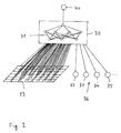
- the risk assessment classifier 30 is shown in more detail in Figure 2 .
- the risk assessment classifier 30 comprises an artificial neural network 31 (deep neural network) depicted only schematically in Figure 2 .
- the network 31 uses as separate input sources every pixel of images 13 captured by the imaging apparatus 12 as well as other sensor data 36, i.e., sensor data 32, 33, 34, 35 originating from the other sensors 20 in Figure 1 (vehicle sensors 21, 22, 23, ).
- the network 31 learns how to assess the traffic risk level of a traffic situation. This is done by feeding reference data into the network 31, composed of reference images 13 taken for example by driving a test car, and reference sensor data 36 measured at the time of the corresponding reference images 13. All reference images 13 have been assessed by a group of test persons in advance, who rate the traffic risk level of the traffic situation shown in each reference image 13. The true traffic risk level may be calculated as an average of all traffic risk levels estimated by the test persons, and is fed to the network 31 as set data together with the corresponding reference data.
- reference output 13 could be obtained by risk level annotations (fed into the network 31 as signal 40) performed by the marking team at the developer of the vision system 10.
- the expert network 31 After the network 31 has been trained how to assess the traffic risk level of numerous traffic situations, representative of essentially all traffic situations occurring in practice, the expert network 31 is implemented into cars for everyday usage. In the car, the images 13 captured by the imaging apparatus 12 together with the corresponding sensor data 36 measured at the time of capturing the images 13 are fed into the network 31. Based on all input sources, the network calculates online and outputs the traffic risk level 40 belonging to the specific traffic situation shown in the image 13 under consideration and corresponding sensor data 36.
- the calculated traffic risk level can be used for different applications.
- a schematic traffic risk indicator 19 is shown with three indicator LEDs, where a green LED indicates low risk, a yellow LED indicates middle risk and a red LED indicates high risk.
- a green LED indicates low risk
- a yellow LED indicates middle risk
- a red LED indicates high risk.
- one multicolor LED can be used instead of multiple single color LEDs.
- more than three colors, for example up to 256 colors can be used for indicating the traffic risk level in a more differentiated manner.
Landscapes
- Physics & Mathematics (AREA)
- General Physics & Mathematics (AREA)
- Traffic Control Systems (AREA)
Priority Applications (1)
| Application Number | Priority Date | Filing Date | Title |
|---|---|---|---|
| EP16192921.1A EP3306590A1 (de) | 2016-10-07 | 2016-10-07 | Fahrerassistenzsystem und -verfahren für ein motorfahrzeug |
Applications Claiming Priority (1)
| Application Number | Priority Date | Filing Date | Title |
|---|---|---|---|
| EP16192921.1A EP3306590A1 (de) | 2016-10-07 | 2016-10-07 | Fahrerassistenzsystem und -verfahren für ein motorfahrzeug |
Publications (1)
| Publication Number | Publication Date |
|---|---|
| EP3306590A1 true EP3306590A1 (de) | 2018-04-11 |
Family
ID=57130193
Family Applications (1)
| Application Number | Title | Priority Date | Filing Date |
|---|---|---|---|
| EP16192921.1A Withdrawn EP3306590A1 (de) | 2016-10-07 | 2016-10-07 | Fahrerassistenzsystem und -verfahren für ein motorfahrzeug |
Country Status (1)
| Country | Link |
|---|---|
| EP (1) | EP3306590A1 (de) |
Cited By (1)
| Publication number | Priority date | Publication date | Assignee | Title |
|---|---|---|---|---|
| CN114008683A (zh) * | 2019-06-14 | 2022-02-01 | 大众汽车股份公司 | 用于运行车辆的驾驶员辅助系统的方法和车辆的驾驶员辅助系统 |
Citations (2)
| Publication number | Priority date | Publication date | Assignee | Title |
|---|---|---|---|---|
| US6226389B1 (en) * | 1993-08-11 | 2001-05-01 | Jerome H. Lemelson | Motor vehicle warning and control system and method |
| US7672764B2 (en) | 2005-08-08 | 2010-03-02 | Denso Corporation | System and method for recording physical response |
-
2016
- 2016-10-07 EP EP16192921.1A patent/EP3306590A1/de not_active Withdrawn
Patent Citations (2)
| Publication number | Priority date | Publication date | Assignee | Title |
|---|---|---|---|---|
| US6226389B1 (en) * | 1993-08-11 | 2001-05-01 | Jerome H. Lemelson | Motor vehicle warning and control system and method |
| US7672764B2 (en) | 2005-08-08 | 2010-03-02 | Denso Corporation | System and method for recording physical response |
Cited By (1)
| Publication number | Priority date | Publication date | Assignee | Title |
|---|---|---|---|---|
| CN114008683A (zh) * | 2019-06-14 | 2022-02-01 | 大众汽车股份公司 | 用于运行车辆的驾驶员辅助系统的方法和车辆的驾驶员辅助系统 |
Similar Documents
| Publication | Publication Date | Title |
|---|---|---|
| US12561585B2 (en) | Systems and methods for classifying driver behavior | |
| US11390276B2 (en) | Control device, control method, and non-transitory storage medium | |
| DE102018002963B4 (de) | Fahrerüberwachungsapparat und fahrerüberwachungsverfahren | |
| CN111164967B (zh) | 图像处理设备和图像处理方法 | |
| CN114612877B (zh) | 用于估计未来路径的系统和方法 | |
| US9767368B2 (en) | Method and system for adaptive ray based scene analysis of semantic traffic spaces and vehicle equipped with such system | |
| US20210089794A1 (en) | Vehicle system and method for detecting objects and object distance | |
| JP4521642B2 (ja) | 車両周辺監視装置、車両、車両周辺監視プログラム | |
| CN109941286A (zh) | 用于评估车辆行驶表面的方法和设备 | |
| EP3252712B1 (de) | Sichtsystem und -verfahren für ein kraftfahrzeug | |
| US9870513B2 (en) | Method and device for detecting objects from depth-resolved image data | |
| KR20170127036A (ko) | 차도 위의 반사체를 인식하고 평가하기 위한 방법 및 장치 | |
| WO2020064543A1 (en) | Vision system and method for a motor vehicle | |
| WO2018212090A1 (ja) | 制御装置及び制御方法 | |
| EP3306590A1 (de) | Fahrerassistenzsystem und -verfahren für ein motorfahrzeug | |
| US20260061999A1 (en) | Driving assistance system, driving assistance device, driving assistance method, and program | |
| JP4590654B2 (ja) | 車両周辺監視装置、車両、車両周辺監視プログラム | |
| EP4435739A1 (de) | Verfahren und system zur zuordnung von umgebungswahrnehmungsdaten mit reibungszustandsinformationen, computerprogramm, computerlesbares speichermedium | |
| DE112018005039T5 (de) | Signalverarbeitungsvorrichtung, signalverarbeitungsverfahren, programm und mobiler körper | |
| JP5742180B2 (ja) | 注視点推定装置 |
Legal Events
| Date | Code | Title | Description |
|---|---|---|---|
| PUAI | Public reference made under article 153(3) epc to a published international application that has entered the european phase |
Free format text: ORIGINAL CODE: 0009012 |
|
| STAA | Information on the status of an ep patent application or granted ep patent |
Free format text: STATUS: THE APPLICATION HAS BEEN PUBLISHED |
|
| AK | Designated contracting states |
Kind code of ref document: A1 Designated state(s): AL AT BE BG CH CY CZ DE DK EE ES FI FR GB GR HR HU IE IS IT LI LT LU LV MC MK MT NL NO PL PT RO RS SE SI SK SM TR |
|
| AX | Request for extension of the european patent |
Extension state: BA ME |
|
| RAP1 | Party data changed (applicant data changed or rights of an application transferred) |
Owner name: VEONEER SWEDEN AB |
|
| STAA | Information on the status of an ep patent application or granted ep patent |
Free format text: STATUS: REQUEST FOR EXAMINATION WAS MADE |
|
| 17P | Request for examination filed |
Effective date: 20180925 |
|
| RBV | Designated contracting states (corrected) |
Designated state(s): AL AT BE BG CH CY CZ DE DK EE ES FI FR GB GR HR HU IE IS IT LI LT LU LV MC MK MT NL NO PL PT RO RS SE SI SK SM TR |
|
| STAA | Information on the status of an ep patent application or granted ep patent |
Free format text: STATUS: EXAMINATION IS IN PROGRESS |
|
| 17Q | First examination report despatched |
Effective date: 20200612 |
|
| STAA | Information on the status of an ep patent application or granted ep patent |
Free format text: STATUS: THE APPLICATION IS DEEMED TO BE WITHDRAWN |
|
| 18D | Application deemed to be withdrawn |
Effective date: 20201223 |