EP3306659A1 - Flüssigkeitsgekühlter kühler und herstellungsverfahren für strahlungsrippe in einem flüssigkeitsgekühlten kühler - Google Patents
Flüssigkeitsgekühlter kühler und herstellungsverfahren für strahlungsrippe in einem flüssigkeitsgekühlten kühler Download PDFInfo
- Publication number
- EP3306659A1 EP3306659A1 EP15894191.4A EP15894191A EP3306659A1 EP 3306659 A1 EP3306659 A1 EP 3306659A1 EP 15894191 A EP15894191 A EP 15894191A EP 3306659 A1 EP3306659 A1 EP 3306659A1
- Authority
- EP
- European Patent Office
- Prior art keywords
- heat
- coolant
- heat radiation
- liquid
- heat sink
- Prior art date
- Legal status (The legal status is an assumption and is not a legal conclusion. Google has not performed a legal analysis and makes no representation as to the accuracy of the status listed.)
- Granted
Links
Images


Classifications
-
- G—PHYSICS
- G06—COMPUTING OR CALCULATING; COUNTING
- G06F—ELECTRIC DIGITAL DATA PROCESSING
- G06F1/00—Details not covered by groups G06F3/00 - G06F13/00 and G06F21/00
- G06F1/16—Constructional details or arrangements
- G06F1/20—Cooling means
-
- F—MECHANICAL ENGINEERING; LIGHTING; HEATING; WEAPONS; BLASTING
- F28—HEAT EXCHANGE IN GENERAL
- F28F—DETAILS OF HEAT-EXCHANGE AND HEAT-TRANSFER APPARATUS, OF GENERAL APPLICATION
- F28F3/00—Plate-like or laminated elements; Assemblies of plate-like or laminated elements
- F28F3/12—Elements constructed in the shape of a hollow panel, e.g. with channels
-
- F—MECHANICAL ENGINEERING; LIGHTING; HEATING; WEAPONS; BLASTING
- F28—HEAT EXCHANGE IN GENERAL
- F28F—DETAILS OF HEAT-EXCHANGE AND HEAT-TRANSFER APPARATUS, OF GENERAL APPLICATION
- F28F13/00—Arrangements for modifying heat-transfer, e.g. increasing, decreasing
- F28F13/06—Arrangements for modifying heat-transfer, e.g. increasing, decreasing by affecting the pattern of flow of the heat-exchange media
- F28F13/08—Arrangements for modifying heat-transfer, e.g. increasing, decreasing by affecting the pattern of flow of the heat-exchange media by varying the cross-section of the flow channels
-
- F—MECHANICAL ENGINEERING; LIGHTING; HEATING; WEAPONS; BLASTING
- F28—HEAT EXCHANGE IN GENERAL
- F28F—DETAILS OF HEAT-EXCHANGE AND HEAT-TRANSFER APPARATUS, OF GENERAL APPLICATION
- F28F3/00—Plate-like or laminated elements; Assemblies of plate-like or laminated elements
- F28F3/02—Elements or assemblies thereof with means for increasing heat-transfer area, e.g. with fins, with recesses, with corrugations
- F28F3/022—Elements or assemblies thereof with means for increasing heat-transfer area, e.g. with fins, with recesses, with corrugations the means being wires or pins
-
- F—MECHANICAL ENGINEERING; LIGHTING; HEATING; WEAPONS; BLASTING
- F28—HEAT EXCHANGE IN GENERAL
- F28F—DETAILS OF HEAT-EXCHANGE AND HEAT-TRANSFER APPARATUS, OF GENERAL APPLICATION
- F28F3/00—Plate-like or laminated elements; Assemblies of plate-like or laminated elements
- F28F3/02—Elements or assemblies thereof with means for increasing heat-transfer area, e.g. with fins, with recesses, with corrugations
- F28F3/06—Elements or assemblies thereof with means for increasing heat-transfer area, e.g. with fins, with recesses, with corrugations the means being attachable to the element
-
- H—ELECTRICITY
- H05—ELECTRIC TECHNIQUES NOT OTHERWISE PROVIDED FOR
- H05K—PRINTED CIRCUITS; CASINGS OR CONSTRUCTIONAL DETAILS OF ELECTRIC APPARATUS; MANUFACTURE OF ASSEMBLAGES OF ELECTRICAL COMPONENTS
- H05K7/00—Constructional details common to different types of electric apparatus
- H05K7/20—Modifications to facilitate cooling, ventilating, or heating
- H05K7/20218—Modifications to facilitate cooling, ventilating, or heating using a liquid coolant without phase change in electronic enclosures
- H05K7/20254—Cold plates transferring heat from heat source to coolant
-
- H—ELECTRICITY
- H05—ELECTRIC TECHNIQUES NOT OTHERWISE PROVIDED FOR
- H05K—PRINTED CIRCUITS; CASINGS OR CONSTRUCTIONAL DETAILS OF ELECTRIC APPARATUS; MANUFACTURE OF ASSEMBLAGES OF ELECTRICAL COMPONENTS
- H05K7/00—Constructional details common to different types of electric apparatus
- H05K7/20—Modifications to facilitate cooling, ventilating, or heating
- H05K7/2039—Modifications to facilitate cooling, ventilating, or heating characterised by the heat transfer by conduction from the heat generating element to a dissipating body
-
- H—ELECTRICITY
- H10—SEMICONDUCTOR DEVICES; ELECTRIC SOLID-STATE DEVICES NOT OTHERWISE PROVIDED FOR
- H10W—GENERIC PACKAGES, INTERCONNECTIONS, CONNECTORS OR OTHER CONSTRUCTIONAL DETAILS OF DEVICES COVERED BY CLASS H10
- H10W40/00—Arrangements for thermal protection or thermal control
- H10W40/40—Arrangements for thermal protection or thermal control involving heat exchange by flowing fluids
- H10W40/47—Arrangements for thermal protection or thermal control involving heat exchange by flowing fluids by flowing liquids, e.g. forced water cooling
-
- H—ELECTRICITY
- H10—SEMICONDUCTOR DEVICES; ELECTRIC SOLID-STATE DEVICES NOT OTHERWISE PROVIDED FOR
- H10W—GENERIC PACKAGES, INTERCONNECTIONS, CONNECTORS OR OTHER CONSTRUCTIONAL DETAILS OF DEVICES COVERED BY CLASS H10
- H10W70/00—Package substrates; Interposers; Redistribution layers [RDL]
- H10W70/01—Manufacture or treatment
- H10W70/02—Manufacture or treatment of conductive package substrates serving as an interconnection, e.g. of metal plates
- H10W70/027—Mechanical treatments, e.g. deforming, punching or cutting
-
- G—PHYSICS
- G06—COMPUTING OR CALCULATING; COUNTING
- G06F—ELECTRIC DIGITAL DATA PROCESSING
- G06F2200/00—Indexing scheme relating to G06F1/04 - G06F1/32
- G06F2200/20—Indexing scheme relating to G06F1/20
- G06F2200/201—Cooling arrangements using cooling fluid
-
- H—ELECTRICITY
- H10—SEMICONDUCTOR DEVICES; ELECTRIC SOLID-STATE DEVICES NOT OTHERWISE PROVIDED FOR
- H10W—GENERIC PACKAGES, INTERCONNECTIONS, CONNECTORS OR OTHER CONSTRUCTIONAL DETAILS OF DEVICES COVERED BY CLASS H10
- H10W40/00—Arrangements for thermal protection or thermal control
- H10W40/20—Arrangements for cooling
- H10W40/25—Arrangements for cooling characterised by their materials
- H10W40/258—Metallic materials
-
- H—ELECTRICITY
- H10—SEMICONDUCTOR DEVICES; ELECTRIC SOLID-STATE DEVICES NOT OTHERWISE PROVIDED FOR
- H10W—GENERIC PACKAGES, INTERCONNECTIONS, CONNECTORS OR OTHER CONSTRUCTIONAL DETAILS OF DEVICES COVERED BY CLASS H10
- H10W40/00—Arrangements for thermal protection or thermal control
- H10W40/20—Arrangements for cooling
- H10W40/25—Arrangements for cooling characterised by their materials
- H10W40/259—Ceramics or glasses
-
- H—ELECTRICITY
- H10—SEMICONDUCTOR DEVICES; ELECTRIC SOLID-STATE DEVICES NOT OTHERWISE PROVIDED FOR
- H10W—GENERIC PACKAGES, INTERCONNECTIONS, CONNECTORS OR OTHER CONSTRUCTIONAL DETAILS OF DEVICES COVERED BY CLASS H10
- H10W70/00—Package substrates; Interposers; Redistribution layers [RDL]
- H10W70/60—Insulating or insulated package substrates; Interposers; Redistribution layers
- H10W70/67—Insulating or insulated package substrates; Interposers; Redistribution layers characterised by their insulating layers or insulating parts
- H10W70/69—Insulating materials thereof
- H10W70/692—Ceramics or glasses
-
- H—ELECTRICITY
- H10—SEMICONDUCTOR DEVICES; ELECTRIC SOLID-STATE DEVICES NOT OTHERWISE PROVIDED FOR
- H10W—GENERIC PACKAGES, INTERCONNECTIONS, CONNECTORS OR OTHER CONSTRUCTIONAL DETAILS OF DEVICES COVERED BY CLASS H10
- H10W90/00—Package configurations
Definitions
- the present invention relates to a liquid-type cooling apparatus provided with a heat sink for radiating heat from a heating body to coolant and relates to a manufacturing method for a heat radiation fin in the liquid-type cooling apparatus.
- the temperature of a heat-generating device thermally connected with the coolant in the downstream region is higher than that of a heat-generating device thermally connected with the coolant in the upstream region; thus, a temperature difference occurs between the heat-generating devices.
- the occurrence of a temperature difference between heat-generating devices poses a problem that there occur variations in the lifetimes of the heat-generating devices or variations in the characteristics of the heat-generating devices; therefore, it is desired to contrive a method for preventing the occurrence of a temperature difference between the heat-generating device in the upstream region and the heat-generating device in the downstream region even when there occurs a temperature difference between the coolant in the upstream region and the coolant in the downstream region.
- the heat radiation amount is proportional to the temperature difference between the heat-generating device and the coolant; thus, when a non-uniform temperature distribution occurs in the coolant and hence the temperature of the coolant in the region close to the heat-generating surface becomes high, the cooling performance is deteriorated.
- the temperature distribution of a coolant is made uniform in a cross section perpendicular to the flowing direction of the coolant; in order to make the temperature distribution of the coolant uniform in the cross section perpendicular to the flowing direction of the coolant, the method of stirring the coolant sufficiently is effective.
- liquid-type cooling apparatus e.g., refer to Patent Document 2
- fins are arranged on two surfaces that face each other in a coolant path so that the coolant is stirred
- a liquid-type cooling apparatus e.g., refer to Patent Document 3
- depressions and protrusions for guiding a coolant are provided in the surfaces of comb-like heat radiation fins so that the coolant is stirred.
- the temperature of the coolant in the downstream region is higher than that of the coolant in the upstream region, due to heat transferred from a heat-generating device in the upstream region. Accordingly, the temperature of a heat-generating device thermally connected with the coolant in the downstream region is higher than that of a heat-generating device thermally connected with the coolant in the upstream region; thus, a temperature difference occurs between the heat-generating devices.
- the occurrence of a temperature difference between heat-generating devices poses a problem that there occur variations in the lifetimes of the heat-generating devices or variations in the characteristics of the heat-generating devices.
- the liquid-type cooling apparatus disclosed in Patent Document 2 is configured in such a way that fins are arranged on two surfaces, in the cooling apparatus, that face each other, and the fins that contribute to heat radiation are only the ones arranged on the surface that is thermally connected with the heat-generating device. Although the fins arranged on the other surface each have a function of stirring the coolant, they do not contribute to heat radiation. As described above, in the case of the conventional liquid-type cooling apparatus disclosed in Patent Document 2, it is required that the fins that do not contribute heat radiation are provided in the cooling apparatus; thus, there has been a problem that the cooling apparatus is upsized.
- the foregoing conventional liquid-type cooling apparatus disclosed in Patent Document 3 is has a structure in which depressions and protrusions for guiding a coolant are provided in the surfaces of comb-like heat radiation fins so that the coolant is stirred and in which the heat radiation fins are arranged only the surface that is thermally connected with the heat-generating device; thus, although downsizing is possible to some extent, the effect of the depressions and protrusions cannot be provided to the coolant that flows into the region that is away from the depressions and protrusions in the surfaces of the heat radiation fins, i.e., the vicinity of the middle portion between the heat radiation fins; therefore, there has been a problem that the stirring effect cannot sufficiently be obtained.
- the present invention has been implemented in order to solve the foregoing problems in the conventional technology; the objective thereof is to provide a liquid-type cooling apparatus that can suppress the temperature difference between the upstream and downstream ends of each of heat-generating devices.
- the objective of the present invention is to provide a liquid-type cooling apparatus provided with a heat radiation fin that can effectively stir a coolant.
- the objective of the present invention is to provide a manufacturing method, for a heat radiation fin, that makes it possible to readily manufacture a heat radiation fin in a liquid-type cooling apparatus.
- a liquid-type cooling apparatus is a liquid-type cooling apparatus in which there are provided a jacket including a coolant path through which a coolant flows and a heat sink that directly or indirectly makes contact with at least one heat-generating device and makes contact with the coolant flowing in the jacket and in which heat generated by the heat-generating device is transferred to the coolant through the intermediary of the heat sink so that the heat is radiated;
- the liquid-type cooling apparatus is characterized in that in the heat sink, the thermal resistance from a portion where the heat sink directly or indirectly makes contact with the heat-generating device to a portion where the heat sink makes contact with the coolant is set to be a value that is different from the thermal resistance at a different position in the flowing direction of the coolant.
- a liquid-type cooling apparatus is a liquid-type cooling apparatus in which there are provided a jacket including a coolant path through which a coolant flows and a heat sink that makes contact with the coolant flowing in the jacket and in which heat generated by a heat-generating device is transferred to the coolant through the intermediary of the heat sink so that the heat is radiated;
- the liquid-type cooling apparatus is characterized in that the heat sink includes a heat sink base member having a first surface portion that faces the inside of the jacket and a plurality of heat radiation fins that are provided on the first surface portion of the heat sink base member and make contact with the coolant flowing in the jacket and in that the plurality of heat radiation fins are inclined toward the downstream side of the coolant flowing in the jacket.
- a manufacturing method for heat radiation fins of the liquid-type cooling apparatus is characterized in that on the first surface portion of the heat sink base member, a plate-shaped heat radiation fin region protruding by a predetermined dimension from the first surface portion is formed and in that a plurality of circular blades that are arranged in such a way as to be spaced a predetermined distance away from one another and whose diameters are different from one another are rotated and then the plurality of circular blades concurrently cut the heat radiation fin region at an inclination angle with respect to the first surface portion so that the plurality of heat radiation fins are formed.
- a manufacturing method for heat radiation fins of the liquid-type cooling apparatus is characterized in that on the first surface portion of the heat sink base member, there are formed a plurality of protruding threads that are arranged in parallel with one another and that each protrude by a predetermined dimension from the first surface portion, in that each of the plurality of protruding threads includes an inclined protruding thread portion that is provided in such a way as to make contact with the first surface portion and is inclined toward a predetermined direction with respect to the first surface portion and an erect protruding thread portion that is provided in such a way as to make contact with the inclined protruding thread portion and stands erect with respect to the first surface portion, and in that the plurality of heat radiation fins are formed through cutting processing of the plurality of protruding threads.
- the thermal resistance, of the heat sink, from a portion where the heat sink directly or indirectly makes contact with the heat-generating device to a portion where the heat sink makes contact with the coolant is set to be a value that is different from the thermal resistance at a different position in the flowing direction of the coolant; thus, it is made possible to suppress the temperature difference between the upstream and downstream ends of each of the heat-generating devices.
- a liquid-type cooling apparatus because a plurality of heat radiation fins are inclined toward the downstream side of the coolant flowing in the jacket, the coolant is stirred along the side face of the heat radiation fin in the direction parallel to the first surface portion of the heat sink base member and in the direction perpendicular thereto; thus, it is made possible to make the temperature distribution of a coolant uniform in a cross section perpendicular to the flowing direction of the coolant and hence the deterioration in the cooling performance can be suppressed. Accordingly, because the heat radiation fins need to be arranged only on the side where heat generating devices are disposed, there is demonstrated an effect that the liquid-type cooling apparatus can be downsized. Moreover, because it is not required to provide a header, which is a coolant flow path assembly portion, there is demonstrated an effect that the liquid-type cooling apparatus can be downsized.
- a plate-shaped heat radiation fin region protruding by a predetermined dimension from the first surface portion is formed, and a plurality of circular blades that are arranged in such a way as to be spaced a predetermined distance away from one another and whose diameters are different from one another are rotated and then the plurality of circular blades concurrently cut the heat radiation fin region at an inclination angle with respect to the first surface portion so that the plurality of heat radiation fins are formed; thus, inclined heat radiation fins can considerably readily be formed.
- each of the plurality of protruding threads includes an inclined protruding thread portion that is provided in such a way as to make contact with the first surface portion and is inclined toward a predetermined direction with respect to the first surface portion and an erect protruding thread portion that is provided in such a way as to make contact with the inclined protruding thread portion and stands erect with respect to the first surface portion;
- the plurality of heat radiation fins are formed through cutting processing of the plurality of protruding threads.
- FIG. 1 is an exploded perspective view of a liquid-type cooling apparatus according to Embodiment 1 of the present invention
- FIG. 2 is a plan view of a liquid-type cooling apparatus according to Embodiment 1 of the present invention
- FIG. 3 is an explanatory view schematically illustrating the cross section taken along the W-W line in FIG. 2 .
- the arrow A in each of FIGS. 1 and 3 indicates the flowing direction of a coolant such as water.
- a liquid-type cooling apparatus 100 has a water jacket 7, as a jacket through which a coolant flows, a heat sink 40, a coolant inlet pipe 8, and a coolant outlet pipe 9.
- the water jacket 7 has a bottom portion 71, a circumferential wall portion 72 formed integrally with the bottom portion 71, and a coolant path 6 enclosed by the bottom portion 71 and the circumferential wall portion 72.
- the side, of the coolant path 6, that faces the bottom portion 71 is opened.
- the circumferential wall portion 72 has a pair of short-side portions 721 and 722 that face each other and a pair of long-side portions 723 and 724 that face each other.
- the coolant inlet pipe 8 fixed in the circumferential wall portion 72 penetrates one short-side portion 721 of the circumferential wall portion 72 and then is opened in the coolant path 6.
- the coolant outlet pipe 9 fixed in the circumferential wall portion 72 penetrates the other short-side portion 722 of the circumferential wall portion 72 and then is opened in the coolant path 6.
- the heat sink 40 has a heat sink base member 4 and a great number of heat radiation fins 5, described later, formed on a first surface portion 41 of the heat sink base member 4.
- the heat sink 40 is fixed to the circumferential wall portion 72 of the water jacket 7 in a liquid-tight manner and in such a way that the first surface portion 41 faces the coolant path 6, so that the coolant path 6 is sealed.
- the coolant path 6 is formed of a space constituted by the heat sink base member 4 and the bottom portion 71 and the circumferential wall portion 72 of the water jacket 7.
- the heat radiation fins 5 formed on the first surface portion 41 of the heat sink 40 are inserted into the coolant path 6 of the water jacket 7.
- a first heat-generating device 1, a second heat-generating device 2, and a third heat-generating device 3, which are power semiconductor devices or the like, are each fixed to a second surface portion 42 of the heat sink 40.
- the coolant made of a liquid such as water flows into the coolant path 6 of the water jacket 7 through the coolant inlet pipe 8 and is exhausted to the outside of the coolant path 6 through the coolant outlet pipe 9.
- the coolant that has flown into the coolant path 6 cools the first heat-generating device 1, the second heat-generating device 2, and the third heat-generating device 3, through the intermediaries of the heat radiation fins 5 and the heat sink base member 4.
- the first heat-generating device 1 is disposed at the most upstream side, with respect to the other heat-generating devices, in the flowing direction A of the coolant in the coolant path 6;
- the third heat-generating device 3 is disposed at the most downstream side, with respect to the other heat-generating devices, in the flowing direction A of the coolant in the coolant path 6;
- the second heat-generating device 2 is disposed between the first heat-generating device 1 and the third heat-generating device 3.
- R 1U , R 1D , R 2U , R 2D , R 3U , and R 3D denote the thermal resistance between the upstream-side portion of the heat-generating device 1 and the coolant, the thermal resistance between the downstream-side portion of the heat-generating device 1 and the coolant, the thermal resistance between the upstream-side portion of the heat-generating device 2 and the coolant, the thermal resistance between the downstream-side portion of the heat-generating device 2 and the coolant, the thermal resistance between the upstream-side portion of the heat-generating device 3 and the coolant, and the thermal resistance between the downstream-side portion of the heat-generating device 3 and the coolant, respectively.
- Tw 1U , Tw 1D , Tw 2U , Tw 2D , Tw 3U , and Tw 3D denote the temperature of the coolant directly under the upstream-side portion of the heat-generating device 1, the temperature of the coolant directly under the downstream-side portion of the heat-generating device 1, the temperature of the coolant directly under the upstream-side portion of the heat-generating device 2, the temperature of the coolant directly under the downstream-side portion of the heat-generating device 2, the temperature of the coolant directly under the upstream-side portion of the heat-generating device 3, and the temperature of the coolant directly under the downstream-side portion of the heat-generating device 3, respectively.
- the temperature of the coolant in the downstream region becomes higher than that of the coolant in the upstream region, due to heat transfer from the heat-generating device disposed in the upstream region. Accordingly, the relative relationships among the respective foregoing temperatures of the coolant are expressed as follows. Tw 1 U ⁇ Tw 1 D ⁇ Tw 2 U ⁇ Tw 2 D ⁇ Tw 3 U ⁇ Tw 3 D
- Tc 1U , Tc 1D , TC 2U , Tc 2D , Tc 3U , and Tc 3D denote the temperature of the upstream-side portion of the heat-generating device 1, the temperature of the downstream-side portion of the heat-generating device 1, the temperature of the upstream-side portion of the heat-generating device 2, the temperature of the downstream-side portion of the heat-generating device 2, the temperature of the upstream-side portion of the heat-generating device 3, and the temperature of the downstream-side portion of the heat-generating device 3, respectively.
- the thermal resistance is set in such a way as to continuously decrease in the flowing direction of the coolant in accordance with the temperature rise of the coolant, as described above; thus, the differences among the respective temperatures of the heat-generating devices 1, 2, and 3 are suppressed. Moreover, by appropriately adjusting the thermal resistances, it is made possible to make the temperatures of all the heat-generating devices equal. In other words, the following equations can be established.
- the thermal resistance is set in such a way as to decrease continuously in the flowing direction of the coolant; the setting of the thermal resistance can specifically be performed through any one of the following means or by combining these means.
- the number of the heat-generating devices is three has been described, for the sake of simplicity; however, it goes without saying that the number of the heat-generating devices may be arbitrary. Moreover, in the foregoing explanation, it has been assumed that all the respective heat generation amounts of the heat-generating devices are one and the same; however, it goes without saying that the heat generation amount may differ depending on the heat-generating device and hence it may be allowed that the thermal resistance is increased or decreased in accordance with the heat generation amount of each of the heat-generating devices.
- the heat radiation fin 5 has a shape in which two or more plates having a predetermined thickness are arranged side by side or in which two or more pillars such as columns, elliptic columns, cones, elliptic cones, prisms, and pyramids are arranged side by side.
- the thermal resistance is not necessarily required that the thermal resistance is gradually decreased toward the downstream side in the flowing direction of the coolant; it may be allowed that in the coolant path 6, the thermal resistance is appropriately increased or decreased in accordance with the cooling priority of the heat-generating device.
- the liquid-type cooling apparatus according to Embodiment 2 of the present invention is characterized in that in a space from a heat-generating device disposed at the most upstream side in the flowing direction of a coolant to a heat-generating device disposed at the most downstream side, the cross-sectional area of the coolant path is changed in accordance with the temperature rise of the coolant.
- FIG. 4 is an exploded perspective view of the liquid-type cooling apparatus according to Embodiment 2 of the present invention
- FIG. 5 is an exploded perspective view of a variant example of the liquid-type cooling apparatus according to Embodiment 2 of the present invention.
- the arrow A in each of FIGS. 4 and 5 indicates the flowing direction of a coolant.
- V 1 and V 2 denote the flow rate of the coolant in a region where the cross-sectional area of the coolant path 6 is large and the flow rate of the coolant in a region where the cross-sectional area of the coolant path 6 is small, respectively.
- the liquid-type cooling apparatus is configured in such a way that the cross-sectional area of the coolant path 6 is decreased in accordance with the continuous temperature rise of the coolant in the space from the most upstream side of the coolant in the coolant path 6 to the most downstream side. Accordingly, the flow rate of the coolant increases in accordance with the decrease in the cross-sectional area of the coolant path 6 (V 1 ⁇ V 2 ). When the flow rate of the coolant increases, the heat radiation capability of the heat radiation fin 5 increases; thus, the thermal resistance decreases.
- the cross-sectional area of the coolant path 6 is gradually decreased in the transverse direction of the water jacket 7 and toward the downstream side in the flowing direction of the coolant.
- the number of the heat radiation fins 5 is adjusted in accordance with the cross-sectional area of the coolant path 6. That is to say, the number of the heat radiation fins 5 gradually decreases toward the downstream side in the flowing direction A of the coolant.
- the cross-sectional area of the coolant path 6 is gradually decreased in the thickness direction of the water jacket 7, i.e. , in a direction (height direction) perpendicular to in the flowing direction of the coolant, and toward the downstream side in the flowing direction of the coolant.
- the height of the heat radiation fin 5 is adjusted in accordance with the cross-sectional area of the coolant path 6. That is to say, the height of the heat radiation fins 5 gradually decreases toward the downstream side in the flowing direction A of the coolant.
- the cross-sectional area of the coolant path 6 is not necessarily required that the cross-sectional area of the coolant path 6 is gradually decreased toward the downstream side in the flowing direction of the coolant; it may be allowed that the cross-sectional area of the coolant path 6 is appropriately increased or decreased in accordance with the cooling priority of the heat-generating device.
- the liquid-type cooling apparatus according to Embodiment 3 of the present invention is characterized in that in a space from a heat-generating device disposed at the most upstream side in the flowing direction of a coolant to a heat-generating device disposed at the most downstream side, the height of the heat radiation fin is changed in accordance with the temperature rise of the coolant.
- FIG. 6 is a cross-sectional view, taken along the flowing direction of a coolant, of the liquid-type cooling apparatus according to Embodiment 3 of the present invention.
- the arrow A in FIG. 6 indicates the flowing direction of a coolant.
- the height of the heat radiation fins 5 gradually increases toward the downstream side in the flowing direction A of the coolant.
- the surface area of the heat radiation fins 5 increases in proportion to the increase in the height of the heat radiation fins 5.
- the height of the heat radiation fins 5 is not necessarily required that the height of the heat radiation fins 5 is gradually increased toward the downstream side in the flowing direction of the coolant; it may be allowed that the height of the heat radiation fins 5 is appropriately increased or decreased in accordance with the cooling priority of the heat-generating device.
- the liquid-type cooling apparatus according to Embodiment 4 of the present invention is characterized in that in a space from a heat-generating device disposed at the most upstream side in the flowing direction of a coolant to a heat-generating device disposed at the most downstream side, the number of heat radiation fins per unit area in the region where the heat radiation fins are arranged is changed in accordance with the temperature rise of the coolant.
- FIG. 7 is a perspective view illustrating a heat sink in the liquid-type cooling apparatus according to Embodiment 4 of the present invention; the heat sink is illustrated in such a way that the heat radiation fins face the top side of the drawing.
- the arrow A in FIG. 7 indicates the flowing direction of a coolant.
- the number of heat radiation fins 5 per unit area in the region where the heat radiation fins are arranged is gradually increased in accordance with the temperature rise of the coolant, i.e., toward the downstream side in the flowing direction of the coolant.
- the number of the heat radiation fins 5 per unit area in the region where the heat radiation fins 5 are arranged is increased toward the downstream side in the flowing direction of the coolant; it may be allowed that the number of the heat radiation fins 5 is appropriately increased or decreased in accordance with the cooling priority of the heat-generating device.
- the liquid-type cooling apparatus according to Embodiment 5 of the present invention is characterized in that in a space from a heat-generating device disposed at the most upstream side in the flowing direction of a coolant to a heat-generating device disposed at the most downstream side, the volume of each of the heat radiation fins is changed in accordance with the temperature rise of the coolant.
- FIG. 8 is a perspective view illustrating a heat sink in the liquid-type cooling apparatus according to Embodiment 5 of the present invention; the heat sink is illustrated in such a way that the heat radiation fins face the top side of the drawing.
- the arrow A in FIG. 8 indicates the flowing direction of a coolant.
- the thickness of the heat radiation fin 5 is gradually increased in accordance with the temperature rise of the coolant so that the volume of each of the heat radiation fins 5 is increased.
- volume of each of the heat radiation fins 5 is increased toward the downstream side in the flowing direction of the coolant; it may be allowed that the volume of the heat radiation fin 5 is appropriately increased or decreased in accordance with the cooling priority of the heat-generating device.
- the liquid-type cooling apparatus according to Embodiment 6 of the present invention is characterized in that the heat radiation fin is inclined toward the downstream side in the flowing direction of a coolant.
- FIG. 9 is a perspective view illustrating a heat sink in the liquid-type cooling apparatus according to Embodiment 6 of the present invention; the heat sink 40 in FIG. 1 is shown upside down so that the first surface portion 41 of the heat sink base member 4 is situated at the upper side of the drawing.
- a great number of heat radiation fins 5, which are aligned lengthwise and breadthwise, are provided on the first surface portion 41 of the heat sink base member 4.
- the longitudinal direction of each of the heat radiation fins 5 is inclined toward the downstream side in the flowing direction A of the coolant.
- the angle ⁇ will be referred to as an inclination angle.
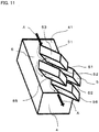
- FIGS. 10 and 11 are explanatory views of the heat sink in the liquid-type cooling apparatus according to Embodiment 6 of the present invention.
- each of the heat radiation fins 5 has a quadrangle-shape cross section in the direction that is perpendicular to the longitudinal direction thereof.
- a quadrangle includes any one of a square, a rectangle, and a diamond.
- a first ridgeline 51 of the heat radiation fin 5 is situated at the most upstream side in the flowing direction A of the coolant, in comparison with the other portions of that heat radiation fin 5; a second ridgeline 52 that is opposite to the first ridgeline 51 is situated at the most downstream side in the flowing direction A of the coolant, in comparison with the other portions of that heat radiation fin 5.
- a row group of heat radiation fins two or more groups of heat radiation fins that are aligned in the direction perpendicular to the flowing direction A of the coolant are each referred to as "a row group of heat radiation fins”; two or more groups of heat radiation fins that are aligned in the flowing direction A of the coolant are each referred to as "a column group of heat radiation fins”.
- a first gap 50a is provided between the adjacent heat radiation fins 5.
- a second gap 50b is provided between the adjacent heat radiation fins 5. Whether or not the respective distances of the first gap 50a and the second gap 50b are the same is no object.
- Each of the heat radiation fins 5 in a row group of heat radiation fins is disposed at a position that is away from the adjacent row group of heat radiation fins by the distance corresponding to the first gap 50a.
- each of the heat radiation fins 5 in a column group of heat radiation fins is disposed at a position that is away from the adjacent column group of heat radiation fins by the distance corresponding to the second gap 50b (refer to FIG.1 ).
- the heat radiation fin 5 is a columnar body that is inclined toward the downstream side in the flowing direction A of the coolant, at a predetermined angle ⁇ with respect to the direction V that is perpendicular to the first surface portion 41 of the heat sink base member 4, and in each of FIGS. 9 , 10 , and 11 , the heat radiation fin 5 is a quadrangular prism whose cross-sectional shape is a quadrangle; however, the shape of the heat radiation fins 5 may be any one of a prism, a pyramid, and the like other than a column, an elliptic column, a cone, an elliptic cone, and a quadrangular prism.
- the heat radiation fin 5 is inclined toward the downstream side in the flowing direction A of the coolant, at a predetermined inclination angle ⁇ with respect to the direction V that is perpendicular to the first surface portion 41 of the heat sink base member 4; therefore, as illustrated in each of FIGS. 10 and 11 , a first fin face 53 and a second fin face 54 that each adjoin the first ridgeline 51 situated at the upstream side in the flowing direction A of the coolant extend at an obtuse angle with respect to the first surface portion 41 of the heat sink base member 4.
- a third fin face 55 and a fourth fin face 56 that each adjoin the second ridgeline 52 situated at the downstream side in the flowing direction A of the coolant extend at an acute angle with respect to the first surface portion 41 of the heat sink base member 4.
- the coolant when making contact with the first and second fin faces 53 and 54 forming side faces of the heat radiation fin 5 that crosses the first surface portion 41 of the heat sink base member 4 at an obtuse angle, the coolant changes its flowing direction not only to the direction that is parallel to the first surface portion 41 of the heat sink base member 4 (refer to arrows indicated by thin solid lines) but also to the direction that is perpendicular to the first surface portion 41 of the heat sink base member 4 in such a way as to depart from the first surface portion 41 of the heat sink base member 4 (refer to arrows indicated by thin broken lines).
- the coolant when making contact with the third and fourth fin faces 55 and 56 forming side faces of the heat radiation fin 5 that crosses the first surface portion 41 of the heat sink base member 4 at an acute angle, the coolant changes its flowing direction not only to the direction that is parallel to the first surface portion 41 of the heat sink base member 4 (refer to arrows indicated by thin solid lines in FIG. 11 ) but also to the direction that is perpendicular to the first surface portion 41 of the heat sink base member 4 in such a way as to approach the first surface portion 41 of the heat sink base member 4 (refer to arrows indicated by thin wave lines in FIG. 11 ).
- the heat radiation fins 5 stir the coolant in the direction parallel to the first surface portion 41 of the heat sink base member 4 and in the direction perpendicular to the first surface portion 41 of the heat sink base member 4.
- the heat radiation fins 5 are arranged in such a way as to be aligned in the row groups of heat radiation fins and in the column groups of heat radiation fins; each of the heat radiation fins 5 in a row group of heat radiation fins is disposed at a position that is away from each corresponding heat radiation fin 5 in the adjacent row group of heat radiation fins by the distance corresponding to the first predetermined gap 50 (refer to FIG. 1 ).
- the coolant cannot advance straightforward in the coolant path 6; thus, the coolant is sufficiently stirred in both the directions, i.e., the direction parallel to the first surface portion 41 of the heat sink base member 4 and the direction perpendicular to the first surface portion 41 of the heat sink base member 4. Therefore, the heat radiation fins 5 need to be provided only on the heat sink base member 4 to which heat-generating devices are fixed; it is not required to provide the heat radiation fins 5 on the bottom portion 71 of the water jacket 7. Accordingly, the liquid-type cooling apparatus can be downsized.
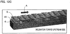
- FIG. 12A is a graph for explaining the heat radiation performance of the liquid-type cooling apparatus; the heat transfer rate of the heat radiation fin is calculated through a numerical simulation and then the heat radiation performances are compared in the graph, based on the difference in the inclination direction.
- the ordinate denotes "the heat transfer rate” [a. u] (arbitrary unit); the abscissa denotes "the distance from the upstream point in the heat radiation fin” [a. u].
- “the distance from the upstream point in the heat radiation fin” is the distance from the portion, of one heat radiation fin 5, that is situated at the most upstream side in the flowing direction A of the coolant to each of portions, of that heat radiation fin, in the longitudinal direction thereof.
- the heat radiation fin 5 is inclined at the foregoing inclination angle ⁇ toward the downstream side in the flowing direction A of the coolant
- the portion, of the heat radiation fin 5, that is situated at the most upstream side in the flowing direction A of the coolant is the root portion, of the heat radiation fin 5, that makes contact with the first surface portion 41 of the heat sink base member 4;
- the distance from the upstream point in the heat radiation fin denotes the distance from the root portion of the heat radiation fin 5 to each of portions in the longitudinal direction of the heat radiation fin 5 that extends in an inclined manner toward the downstream side in the flowing direction A of the coolant.
- the heat radiation fin 5 is inclined at the foregoing inclination angle ⁇ toward the upstream side in the flowing direction A of the coolant, the portion, of the heat radiation fin 5, that is situated at the most upstream side in the flowing direction A of the coolant is the front end portion that is opposite to the root portion of the heat radiation fin 5; thus, "the distance from the upstream point in the heat radiation fin” denotes the distance from the front end portion that is opposite to the root portion of the heat radiation fin 5 to each of portions in the longitudinal direction of the heat radiation fin 5.
- the solid line X represents the heat radiation characteristics of the heat radiation fins 5 at a time when as described in Embodiment 6 of the present invention and as illustrated in FIG. 12B , the heat radiation fins 5 is inclined at the inclination angle ⁇ toward the downstream side in the flowing direction A of the coolant.
- the broken line Y represents the heat radiation characteristics of the heat radiation fins 5 at a time when as illustrated in FIG. 12C , the heat radiation fins 5 is inclined at the inclination angle ⁇ toward the upstream side in the flowing direction A of the coolant.
- the heat radiation fins 5 in the liquid-type cooling apparatus according to Embodiment 6 of the present invention can be produced, for example, through machining, forging, die-casting, or 3-dimension printing of a high-heat-conductivity material such as aluminum, copper, ceramics, or the like.
- the heat radiation fins 5 may be produced in such a way that at the initial production stage for the heat radiation fin, a heat radiation fin is formed to be perpendicular to the first surface portion of the heat sink base member and then external force is applied to the heat radiation fin that has been formed to be perpendicular to the first surface portion so that the heat radiation fin is inclined toward the downstream side in the flowing direction of the coolant.
- depressions and protrusions are provided in the region that is on the first surface portion 41 of the heat sink base member 4 and in which no heat radiation fins 5 exists so that the flow of the coolant is stirred and hence the heat radiation performance is raised; alternatively, it may be allowed that the inclination angle ⁇ of the heat radiation fin 5 is changed in accordance with the location of the heat radiation fin 5 on the first surface portion 41 of the heat sink base member 4.
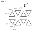
- the liquid-type cooling apparatus according to Embodiment 7 of the present invention is characterized in that the shape of the heat radiation fin is a triangular prism, a quadrangular prism, or a hexagonal prism and in that the heat radiation fins are arranged in such a way that the respective side faces of the adjacent heat radiation fins are parallel to one another.
- the other configurations are the same as those in Embodiment 1 described above.
- FIG. 13 is an explanatory diagram representing a heat radiation fin in the liquid-type cooling apparatus according to Embodiment 7 of the present invention.
- each of the heat radiation fins 501 provided on the first surface portion 41 of the heat sink base member 4 is formed of a triangular prism whose cross section perpendicular to the longitudinal direction thereof is triangular; the heat radiation fins 501 are arranged in such a way that the respective fin faces 501a, of the adjacent heat radiation fins 501, that face one another are parallel to one another.
- the coolant flows in the direction of the arrow A.
- Each of the heat radiation fins 501 is inclined at an inclination angle ⁇ with respect to the flowing direction A of the coolant.
- the other configurations are the same as those in Embodiment 6 described above.
- FIG. 14 is an explanatory diagram representing a variant example of heat radiation fin in the liquid-type cooling apparatus according to Embodiment 7 of the present invention.
- each of the heat radiation fins 502 provided on the first surface portion 41 of the heat sink base member 4 (refer to FIG. 1 and FIGS. 9 through 11 ) is formed of a quadrangular prism whose cross section perpendicular to the longitudinal direction thereof is quadrangular; the heat radiation fins 502 are arranged in such a way that the respective fin faces 502a, of the adjacent heat radiation fins 502, that face one another are parallel to one another.
- the coolant flows in the direction of the arrow A.
- Each of the heat radiation fins 502 is inclined at an inclination angle ⁇ with respect to the flowing direction A of the coolant.
- the other configurations are the same as those in Embodiment 6 described above.
- FIG. 15 is an explanatory diagram representing another variant example of heat radiation fin in the liquid-type cooling apparatus according to Embodiment 7 of the present invention.
- each of the heat radiation fins 503 provided on the first surface portion 41 of the heat sink base member 4 (refer to FIG. 1 and FIGS. 9 through 11) is formed of a hexagonal prism whose cross section perpendicular to the longitudinal direction thereof is hexagonal; the heat radiation fins 503 are arranged in such a way that the respective fin faces 503a, of the adjacent heat radiation fins 503, that face one another are parallel to one another.
- the coolant flows in the direction of the arrow A.
- Each of the heat radiation fins 503 is inclined at an inclination angle ⁇ with respect to the flowing direction A of the coolant.
- the other configurations are the same as those in Embodiment 6 described above.
- Embodiment 7 when making contact with the fin faces that cross the first surface portion 41 of the heat sink base member 4 at an obtuse angle, the coolant changes its flowing direction not only to the direction that is parallel to the first surface portion 41 of the heat sink base member 4 but also to the direction that is perpendicular to the first surface portion 41 of the heat sink base member 4 in such a way as to depart from the first surface portion 41 of the heat sink base member 4.
- the coolant when making contact with the fin faces, of each of the heat radiation fins 501, 502, and 503, that cross the first surface portion 41 of the heat sink base member 4 at an acute angle, the coolant changes its flowing direction not only to the direction that is parallel to the first surface portion 41 of the heat sink base member 4 but also to the direction that is perpendicular to the first surface portion 41 of the heat sink base member 4 in such a way as to approach the first surface portion 41 of the heat sink base member 4.
- each of the heat radiation fins 501, 502, and 503 needs to be provided only on the heat sink base member 4 to which heat-generating devices are fixed; it is not required to provide the heat radiation fins on the bottom portion 71 of the water jacket 7. Accordingly, the liquid-type cooling apparatus can be downsized.
- the shape of the heat radiation fin is a triangular prism, a quadrangular prism, or a hexagonal prism
- adjustment of the dimensions makes it possible to arrange the heat radiation fins in such a way the all respective side faces of the adjacent heat radiation fins are parallel to one another.
- the fact that the respective side faces of the adjacent heat radiation fins are parallel to each other suggests that the gap between the adjacent heat radiation fins is held to a fixed distance, i.e., that the flow rate of the coolant that flows between the adjacent heat radiation fins is held to a fixed value.
- all of the respective sizes of the gaps between the adjacent heat radiation fins are set to the minimum gap size, so that the flow rate of the coolant that flows between the adjacent heat radiation fins can be made maximum in the size restriction. Because the heat radiation capability of the heat radiation fin is proportional to the flow rate of the coolant, the cooling performance of the liquid-type cooling apparatus according to Embodiment 7 of the present invention is raised.
- the manufacturing method for the heat radiation fins in the liquid-type cooling apparatus is characterized in that heat radiation fins are manufactured by use of a cutting tool having a plurality of circular blades whose diameters are different from one another; the manufacturing method is a manufacturing method for heat radiation fins in a liquid-type cooling apparatus at a time when as each of the liquid-type cooling apparatuses according to before-mentioned Embodiments 1 and 2, the heat radiation fins are inclined on the whole from the first surface portion of the heat sink base member toward the downstream side in the flowing direction of the coolant.
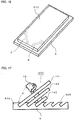
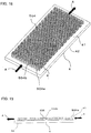
- FIGS. 16 and 17 are explanatory views illustrating a manufacturing method for the heat radiation fin of the liquid-type cooling apparatus according to Embodiment 8 of the present invention.
- a plate-shaped heat radiation fin region 510 having predetermined thickness dimension, longitudinal width dimension, and transverse width dimension is formed on the heat sink base member 4 made of a high-heat conductivity material such as aluminum, copper, or ceramics. It may be allowed that the board thickness of the heat sink base member 4 is set to a value preliminarily including the thickness of the heat radiation fin region 510 and that the plate-shaped heat radiation fin region 510 having predetermined thickness dimension, longitudinal width dimension, and transverse width dimension is formed.
- the heat radiation fin region 510 is cut at a predetermined inclination angle in any one of the directions indicated by the arrows D and E in FIG. 16 so that there are formed inclined grooves that are spaced a predetermined distance away from one another.
- the heat radiation fin region 510 is cut at a predetermined inclination angle in the other one of the directions indicated by the arrows D and E so that there are formed inclined grooves that are spaced a predetermined distance away from one another.
- Inclined grooves are formed in the heat radiation fin region 510 in both directions D and E in such a manner as described above, so that heat radiation fins 505 illustrated in FIG. 17 are formed.
- the cutting tool 200 is formed in such a way that as illustrated in FIG. 17 , the plurality of circular blades 141, 142, and 143 whose diameters are different from one another are fixed on an axle 15 to be evenly spaced a predetermined distance away from one another; a plurality of inclined grooves are concurrently formed in the heat radiation fin region 510 by rotating the axle 15 inclined at an inclination angle ⁇ with respect to the plane of the heat radiation fin region 510, so that a great number of heat radiation fins 505 that are inclined at the inclination angle ⁇ can readily be manufactured.
- the manufacturing method for heat radiation fins in a liquid-type cooling apparatus relates to a manufacturing method for heat radiation fins in a liquid-type cooling apparatus at a time when the heat radiation fins are inclined on the whole from the first surface portion of the heat sink base member toward the downstream side in the flowing direction of the coolant; the manufacturing method is characterized in that the heat radiation fins are manufactured by use of a cutting tool having a plurality of circular blades whose diameters are different from one another.
- a circular blade whose diameter is excessively large and a circular blade whose diameter is excessively small are required.
- a manufacturing method for a liquid-type cooling apparatus and heat radiation fins in the liquid-type cooling apparatus, according to Embodiment 9 of the present invention, is to solve the foregoing problems in the manufacturing method for heat radiation fins, according to Embodiment 8; there is provided a manufacturing method for a liquid-type cooling apparatus having heat radiation fins that can efficiently be manufactured by use of a cutting tool including a plurality of circular blades whose diameters are equal to one another and for the heat radiation fins in the liquid-type cooling apparatus.
- the liquid-type cooling apparatus according to Embodiment 9 of the present invention is characterized in that the heat radiation fin is configured with an inclination portion that makes contact with the first surface portion of the heat sink base member and an erect portion that extends from the inclination portion in a vertical manner with respect to the first surface portion of the heat sink base member.
- the other configurations are the same as those in each of Embodiments 1 and 2, described above.
- FIG. 18 is a perspective view illustrating a heat sink of the liquid-type cooling apparatus according to Embodiment 9 of the present invention
- FIG. 19 is a side view illustrating the heat sink of the liquid-type cooling apparatus according to Embodiment 9 of the present invention.
- the respective heat radiation fins 504 provided on the first surface portion 41 of the heat sink base member 4 are aligned in a column group of heat radiation fins as well as in a row group of heat radiation fins.
- Each of the heat radiation fins 504 is formed of a triangular prism, as illustrated in FIG. 6 , in foregoing Embodiment 2. It goes without saying that the shape thereof may be other than a triangular prism.
- each of the heat radiation fins 504 is configured with an inclination portion 504a that is formed in a portion that makes contact with the first surface portion 41 of the heat sink base member 4, i.e. , in the root portion of the heat radiation fin 504 and an erect portion 504b that extends from the inclination portion 504a in a vertical manner with respect to the first surface portion 41 of the heat sink base member 4.
- the inclination portion 504a of the heat radiation fin 504 is inclined at the inclination angle ⁇ toward the downstream side in the flowing direction A of the coolant.
- the erect portion 504b of the heat radiation fin is configured with portions other than the inclination portion 504a.
- the inclination portion 504a is provided in the root portion of the heat radiation fin 504 and hence the coolant flowing in the vicinity of the first surface portion 41 of the heat sink base member 4 is autonomously stirred, so that the cooling performance of the liquid-type cooling apparatus is raised.
- the manufacturing method for heat radiation fins is a method of manufacturing the heat radiation fins of the liquid-type cooling apparatus illustrated in each of FIGS. 18 and 19 , described above; the manufacturing method is characterized in that after a plurality of comb-like protruding threads that each include an inclination portion are formed through extrusion method or the like, cutting processing is applied to the protruding threads in a vertical manner with respect to the surface portion of the heat sink base member, by use of a plurality of circular blades whose diameters are one and the same, so that heat radiation fins are manufactured.
- the protruding thread is configured with an inclined protruding thread portion formed in the root portion that is connected with the surface portion of the heat sink base member and an erect protruding thread portion that extends from the inclined protrusion portion in a vertical manner with respect to the surface portion of the heat sink base member, a heat radiation fin having the inclined protruding thread portion in the root portion and the erect protruding thread portion is formed even when cutting processing utilizing circular blades is performed in the vertical direction with respect to the surface portion of the heat sink base member.
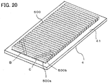
- FIG. 20 is a perspective view for explaining a manufacturing method for the heat radiation fins of the liquid-type cooling apparatus according to Embodiment 9 of the present invention.
- protruding threads 500 that each continuously extend in the row direction are formed in such a way as to be aligned in the column direction, spaced a predetermined distance away from one another, on the first surface portion 41 of the heat sink base member 4 made of a high-heat conductivity material such as aluminum, copper, or ceramics.
- a high-heat conductivity material such as aluminum, copper, or ceramics.
- the protruding thread 500 that continues in the row direction is configured with an inclined protruding thread portion 500a that is formed in a portion that makes contact with the first surface portion 41 of the heat sink base member 4, in such a way as to be inclined at the inclination angle ⁇ , and an erect protruding thread portion 500b that extends from the inclined protruding thread portion 500a in a vertical manner with respect to the first surface portion 41 of the heat sink base member 4.
- the protruding threads 500 formed in the shape of a comb are cut at even intervals in any one of the directions indicated by arrows B and C so that a plurality of grooves having a predetermined width are formed.
- the protruding threads 500 are cut at even intervals in the other one of the directions indicated by arrows B and C so that a plurality of grooves having a predetermined width are formed.
- the plurality of circular blades having the same diameter cut the erect protruding thread portions 500b of the protruding threads 500 in a vertical manner with respect to the first surface portion 41 of the heat sink base member 4.
- the cutting processing makes it possible to manufacture the heat sink 40 in which the respective heat radiation fins 504 illustrated in FIG. 18 are formed.
- the number of circular blades is not limited, unlike Embodiment 8; thus, an increase in the number of circular blades makes it possible to manufacture the heat radiation fins in a considerably efficient and easy manner.
- the present invention can be applied not only to the field of a liquid-type cooling apparatus for cooling heat-generating devices such as semiconductor devices but also to the field in which the liquid-type cooling apparatus is utilized, for example, the field of the automobile industry.
Landscapes
- Engineering & Computer Science (AREA)
- Physics & Mathematics (AREA)
- Thermal Sciences (AREA)
- Microelectronics & Electronic Packaging (AREA)
- General Engineering & Computer Science (AREA)
- Mechanical Engineering (AREA)
- Theoretical Computer Science (AREA)
- Human Computer Interaction (AREA)
- General Physics & Mathematics (AREA)
- Cooling Or The Like Of Electrical Apparatus (AREA)
- Cooling Or The Like Of Semiconductors Or Solid State Devices (AREA)
- Thermotherapy And Cooling Therapy Devices (AREA)
Priority Applications (2)
| Application Number | Priority Date | Filing Date | Title |
|---|---|---|---|
| EP20186458.4A EP3745455B1 (de) | 2015-06-03 | 2015-06-03 | Herstellungsverfahren für wärmestrahlungsrippen in einer flüssigkeitskühlvorrichtung |
| EP19196931.0A EP3627549B1 (de) | 2015-06-03 | 2015-06-03 | Flüssigkeitskühlvorrichtung und herstellungsverfahren für eine wärmestrahlungsrippe in einer flüssigkeitskühlvorrichtung |
Applications Claiming Priority (1)
| Application Number | Priority Date | Filing Date | Title |
|---|---|---|---|
| PCT/JP2015/065988 WO2016194158A1 (ja) | 2015-06-03 | 2015-06-03 | 液冷冷却器、及び液冷冷却器に於ける放熱フィンの製造方法 |
Related Child Applications (4)
| Application Number | Title | Priority Date | Filing Date |
|---|---|---|---|
| EP20186458.4A Division EP3745455B1 (de) | 2015-06-03 | 2015-06-03 | Herstellungsverfahren für wärmestrahlungsrippen in einer flüssigkeitskühlvorrichtung |
| EP20186458.4A Division-Into EP3745455B1 (de) | 2015-06-03 | 2015-06-03 | Herstellungsverfahren für wärmestrahlungsrippen in einer flüssigkeitskühlvorrichtung |
| EP19196931.0A Division EP3627549B1 (de) | 2015-06-03 | 2015-06-03 | Flüssigkeitskühlvorrichtung und herstellungsverfahren für eine wärmestrahlungsrippe in einer flüssigkeitskühlvorrichtung |
| EP19196931.0A Division-Into EP3627549B1 (de) | 2015-06-03 | 2015-06-03 | Flüssigkeitskühlvorrichtung und herstellungsverfahren für eine wärmestrahlungsrippe in einer flüssigkeitskühlvorrichtung |
Publications (3)
| Publication Number | Publication Date |
|---|---|
| EP3306659A1 true EP3306659A1 (de) | 2018-04-11 |
| EP3306659A4 EP3306659A4 (de) | 2019-06-19 |
| EP3306659B1 EP3306659B1 (de) | 2021-08-04 |
Family
ID=57440363
Family Applications (3)
| Application Number | Title | Priority Date | Filing Date |
|---|---|---|---|
| EP20186458.4A Active EP3745455B1 (de) | 2015-06-03 | 2015-06-03 | Herstellungsverfahren für wärmestrahlungsrippen in einer flüssigkeitskühlvorrichtung |
| EP19196931.0A Active EP3627549B1 (de) | 2015-06-03 | 2015-06-03 | Flüssigkeitskühlvorrichtung und herstellungsverfahren für eine wärmestrahlungsrippe in einer flüssigkeitskühlvorrichtung |
| EP15894191.4A Active EP3306659B1 (de) | 2015-06-03 | 2015-06-03 | Flüssigkeitsgekühlter kühler und herstellungsverfahren für strahlungsrippe in einem flüssigkeitsgekühlten kühler |
Family Applications Before (2)
| Application Number | Title | Priority Date | Filing Date |
|---|---|---|---|
| EP20186458.4A Active EP3745455B1 (de) | 2015-06-03 | 2015-06-03 | Herstellungsverfahren für wärmestrahlungsrippen in einer flüssigkeitskühlvorrichtung |
| EP19196931.0A Active EP3627549B1 (de) | 2015-06-03 | 2015-06-03 | Flüssigkeitskühlvorrichtung und herstellungsverfahren für eine wärmestrahlungsrippe in einer flüssigkeitskühlvorrichtung |
Country Status (5)
| Country | Link |
|---|---|
| US (1) | US11003227B2 (de) |
| EP (3) | EP3745455B1 (de) |
| JP (1) | JPWO2016194158A1 (de) |
| CN (1) | CN107615479B (de) |
| WO (1) | WO2016194158A1 (de) |
Cited By (3)
| Publication number | Priority date | Publication date | Assignee | Title |
|---|---|---|---|---|
| EP3454367A4 (de) * | 2016-12-20 | 2019-07-17 | Fuji Electric Co., Ltd. | Halbleitermodul |
| WO2021249680A1 (de) * | 2020-06-08 | 2021-12-16 | Magna powertrain gmbh & co kg | Elektrisches leistungsmodul |
| EP4312262A1 (de) * | 2022-07-29 | 2024-01-31 | Amulaire Thermal Technology, Inc. | Wassergekühlte fahrzeugkühlkörperplatte mit rippensätzen mit verschiedenen oberflächenbereichen |
Families Citing this family (75)
| Publication number | Priority date | Publication date | Assignee | Title |
|---|---|---|---|---|
| US20170363375A1 (en) * | 2015-06-30 | 2017-12-21 | Georgia Tech Research Corporation | Heat exchanger with variable density feature arrays |
| US10809017B2 (en) * | 2016-05-10 | 2020-10-20 | Mitsubishi Electric Corporation | Heat sink with projection and recess shaped fins |
| JP6662242B2 (ja) * | 2016-08-24 | 2020-03-11 | トヨタ自動車株式会社 | 半導体装置 |
| JP6868633B2 (ja) * | 2016-09-23 | 2021-05-12 | 住友精密工業株式会社 | 冷却装置 |
| US10492334B2 (en) | 2017-01-12 | 2019-11-26 | Rensselaer Polytechnic Institute | Methods, systems, and assemblies for cooling an electronic component |
| JP6462737B2 (ja) | 2017-01-24 | 2019-01-30 | 三菱電機株式会社 | ヒートシンク |
| JP6880776B2 (ja) * | 2017-01-27 | 2021-06-02 | 株式会社デンソー | 電力変換装置 |
| WO2018146816A1 (ja) * | 2017-02-13 | 2018-08-16 | 新電元工業株式会社 | 電子機器 |
| CN110383470B (zh) * | 2017-03-16 | 2023-05-09 | 三菱电机株式会社 | 冷却系统 |
| US10766097B2 (en) * | 2017-04-13 | 2020-09-08 | Raytheon Company | Integration of ultrasonic additive manufactured thermal structures in brazements |
| CN107680964A (zh) * | 2017-11-07 | 2018-02-09 | 苏州科技大学 | 一种改善功率单元温度均匀性的微波功率放大器 |
| SE1730353A1 (sv) * | 2017-12-28 | 2019-06-29 | Andersson Inge | Kylanordning |
| CN108024486A (zh) * | 2018-01-04 | 2018-05-11 | 钦州学院 | 基于蜻蜓翅膀微观表面的微型散热器及其制造方法 |
| JP7230333B2 (ja) * | 2018-03-30 | 2023-03-01 | 日本電産株式会社 | コールドプレート |
| EP3564992B1 (de) * | 2018-05-02 | 2021-07-07 | EKWB d.o.o. | Fluidbasierte kühlvorrichtung zum kühlen von mindestens zwei verschiedenen ersten wärmeerzeugenden elementen einer wärmequellenanordnung |
| WO2019231399A1 (en) * | 2018-05-28 | 2019-12-05 | National University Of Singapore | A heat sink assembly |
| US10617035B2 (en) * | 2018-05-29 | 2020-04-07 | Raytheon Company | Additively manufactured structures for gradient thermal conductivity |
| US10976119B2 (en) * | 2018-07-30 | 2021-04-13 | The Boeing Company | Heat transfer devices and methods of transfering heat |
| JP7087850B2 (ja) * | 2018-09-05 | 2022-06-21 | 株式会社デンソー | 半導体装置 |
| GB2578738B (en) * | 2018-11-05 | 2020-12-09 | Xerotech Ltd | Thermal management system for a battery |
| US11129310B2 (en) * | 2018-11-22 | 2021-09-21 | Fuji Electric Co., Ltd. | Semiconductor module, vehicle and manufacturing method |
| JP6918765B2 (ja) * | 2018-11-29 | 2021-08-11 | ファナック株式会社 | 放熱装置 |
| EP3671828A1 (de) * | 2018-12-21 | 2020-06-24 | Nederlandse Organisatie voor toegepast- natuurwetenschappelijk onderzoek TNO | Mikrochip-verdunstungskühlung |
| EP3735117A1 (de) * | 2019-05-03 | 2020-11-04 | Siemens Aktiengesellschaft | Kühlung von seriell in einem kühlmittelstrom angeordneten wärmequellen |
| EP3969829A4 (de) * | 2019-05-14 | 2023-01-18 | Holo, Inc. | Vorrichtungen, systeme und verfahren zur wärmeverwaltung |
| TWI713417B (zh) | 2019-05-16 | 2020-12-11 | 禾榮科技股份有限公司 | 散熱結構及使用其的中子束產生裝置 |
| JP2020017720A (ja) * | 2019-07-04 | 2020-01-30 | 日本軽金属株式会社 | ヒートシンク |
| JP7367418B2 (ja) * | 2019-09-13 | 2023-10-24 | 富士電機株式会社 | 半導体モジュールおよび車両 |
| CN110678043B (zh) * | 2019-09-30 | 2021-01-19 | 潍柴动力股份有限公司 | 一种液冷散热器和一种电机控制器 |
| KR102678254B1 (ko) * | 2019-10-16 | 2024-06-26 | 현대모비스 주식회사 | 냉각 장치 및 그 냉각 장치를 이용한 인버터 |
| CN110864578A (zh) * | 2019-12-02 | 2020-03-06 | 西安热工研究院有限公司 | 一种用于超临界二氧化碳pche的变截面机翼型高效换热通道 |
| CN112925399B (zh) * | 2019-12-06 | 2025-02-25 | 辉达公司 | 带有显示侧冷却系统的膝上型计算机 |
| US11460897B2 (en) | 2019-12-06 | 2022-10-04 | Nvidia Corporation | Laptop computer with display-side cooling system |
| JP6874823B1 (ja) * | 2019-12-26 | 2021-05-19 | 株式会社明電舎 | 冷却構造及びヒートシンク |
| KR102296543B1 (ko) * | 2019-12-31 | 2021-08-31 | 고려대학교 산학협력단 | 수냉식 히트싱크 |
| KR20210088329A (ko) * | 2020-01-06 | 2021-07-14 | 엘지전자 주식회사 | 전력 모듈 |
| US11149937B2 (en) * | 2020-01-30 | 2021-10-19 | Toyota Motor Engineering & Manufacturing North America, Inc. | Functionally graded manifold microchannel heat sinks |
| WO2021186891A1 (ja) * | 2020-03-18 | 2021-09-23 | 富士電機株式会社 | 半導体モジュール |
| US20210358833A1 (en) * | 2020-05-14 | 2021-11-18 | Lite-On Semiconductor Corporation | Direct cooling power semiconductor package |
| CN114518787A (zh) * | 2020-11-20 | 2022-05-20 | 深圳比特微电子科技有限公司 | 液冷虚拟货币挖矿机及液冷散热装置 |
| CN114068450A (zh) * | 2020-07-30 | 2022-02-18 | 舍弗勒技术股份两合公司 | 印刷电路板部件用冷却部件及印刷电路系统 |
| CN112071217A (zh) * | 2020-09-02 | 2020-12-11 | Tcl华星光电技术有限公司 | 一种显示装置 |
| EP4006968B1 (de) | 2020-11-26 | 2023-03-22 | Hitachi Energy Switzerland AG | Leistungshalbleiterbauelement |
| EP4281651B1 (de) * | 2021-01-21 | 2026-03-04 | Parker-Hannifin Corporation | Wärmetauscher mit progressiv geteiltem strömungskreis, struktureller lasttragender konstruktion |
| KR102862230B1 (ko) * | 2021-01-28 | 2025-09-19 | 엘에스일렉트릭(주) | 전력기기용 히트싱크 |
| CN112928082A (zh) * | 2021-02-07 | 2021-06-08 | 阳光电源股份有限公司 | 液冷板及功率模组 |
| US12041754B1 (en) * | 2021-05-07 | 2024-07-16 | Core Scientific, Inc. | Heat sink that varies in height |
| JP7574734B2 (ja) * | 2021-05-10 | 2024-10-29 | 日本軽金属株式会社 | ヒートシンク及びヒートシンクの製造方法 |
| WO2023282307A1 (ja) * | 2021-07-09 | 2023-01-12 | 株式会社アイシン | 回転電機用の冷却部材、回転電機、回転電機用の冷却部材の製造方法 |
| JP7675582B2 (ja) * | 2021-07-12 | 2025-05-13 | ニデック株式会社 | 放熱部材 |
| DE102021211059A1 (de) * | 2021-10-01 | 2023-04-06 | Robert Bosch Gesellschaft mit beschränkter Haftung | Kühler zum Kühlen einer Leistungselektronik |
| US12035510B2 (en) * | 2021-12-03 | 2024-07-09 | Toyota Motor Engineering & Manufacturing North America, Inc. | Cold plate with embedded power device, driver circuit, and microcontroller with 3D printed circuit board |
| JP2023096940A (ja) * | 2021-12-27 | 2023-07-07 | ニデック株式会社 | 放熱部材および冷却装置 |
| CN114594837B (zh) * | 2022-03-14 | 2024-04-16 | 英业达科技有限公司 | 一种cpu液冷板 |
| JP2023135729A (ja) * | 2022-03-16 | 2023-09-29 | ニデック株式会社 | 冷却部材 |
| JP2023144350A (ja) * | 2022-03-28 | 2023-10-11 | 株式会社 日立パワーデバイス | パワー半導体モジュール及び電力変換装置 |
| US12007180B2 (en) * | 2022-04-01 | 2024-06-11 | Hamilton Sundstrand Corporation | Varying topology heat sinks |
| US12313350B2 (en) | 2022-04-01 | 2025-05-27 | Hamilton Sundstrand Corporation | Varying topology heat sinks |
| CN115397187B (zh) * | 2022-04-07 | 2023-09-05 | 安世半导体科技(上海)有限公司 | 用于车辆功率模块的散热器的设计方法 |
| KR102682920B1 (ko) * | 2022-05-19 | 2024-07-09 | 동양피스톤 주식회사 | 파워 모듈 냉각 장치 |
| KR102712734B1 (ko) * | 2022-05-19 | 2024-10-04 | 동양피스톤 주식회사 | 파워 모듈 냉각 장치 |
| CN119422247A (zh) * | 2022-06-20 | 2025-02-11 | 尼得科株式会社 | 冷却装置及半导体装置 |
| CN115226290B (zh) * | 2022-07-04 | 2025-06-06 | 中国电子科技集团公司第二十九研究所 | 一种基于内嵌微流道印制电路板的微波组件的制备方法 |
| CN115460865A (zh) * | 2022-08-15 | 2022-12-09 | 北京比特大陆科技有限公司 | 冷却板、线路板组件及液冷服务器 |
| JP7455180B1 (ja) | 2022-11-30 | 2024-03-25 | 星和電機株式会社 | 熱放射制御部材及びそれを用いた電子機器並びに熱放射制御部材の製造方法 |
| US12120845B2 (en) * | 2022-12-28 | 2024-10-15 | Amulaire Thermal Technology, Inc. | Liquid-cooling heat dissipation plate with unequal height pin-fins and enclosed liquid-cooling cooler having the same |
| US20240365520A1 (en) * | 2023-04-26 | 2024-10-31 | Atieva, Inc. | Thermal device with gradient pin fins for electronics |
| WO2024226316A1 (en) * | 2023-04-26 | 2024-10-31 | Atieva, Inc. | Thermal device with gradient pin fins for electronics |
| IT202300014145A1 (it) * | 2023-07-06 | 2025-01-06 | Marelli Europe Spa | Sistema di raffreddamento per un modulo di potenza e modulo di potenza provvisto di detto sistema di raffreddamento |
| CN117038473B (zh) * | 2023-09-19 | 2024-01-23 | 毫厘机电(苏州)有限公司 | 一种液冷散热器的制作方法及液冷散热器 |
| WO2025191702A1 (ja) * | 2024-03-12 | 2025-09-18 | 三菱電機株式会社 | 冷却装置、および半導体装置 |
| WO2025191203A1 (en) * | 2024-03-13 | 2025-09-18 | Oy Hollmén & Co | Heat sink |
| US20250305776A1 (en) * | 2024-03-27 | 2025-10-02 | Denso International America, Inc. | Joined pin fins heat sink |
| US20250386471A1 (en) * | 2024-06-14 | 2025-12-18 | Amulaire Thermal Technology, Inc. | Liquid-cooling cooler for power module of electric vehicle |
| CN119517871A (zh) * | 2024-11-27 | 2025-02-25 | 中航光电科技股份有限公司 | 一种用于高功率密度器件的封装散热结构 |
Family Cites Families (54)
| Publication number | Priority date | Publication date | Assignee | Title |
|---|---|---|---|---|
| JPS5549387A (en) | 1978-10-05 | 1980-04-09 | Mitsubishi Chem Ind Ltd | Organo-silane compound |
| US4953634A (en) | 1989-04-20 | 1990-09-04 | Microelectronics And Computer Technology Corporation | Low pressure high heat transfer fluid heat exchanger |
| US5002123A (en) * | 1989-04-20 | 1991-03-26 | Microelectronics And Computer Technology Corporation | Low pressure high heat transfer fluid heat exchanger |
| JP3236137B2 (ja) * | 1993-07-30 | 2001-12-10 | 富士通株式会社 | 半導体素子冷却装置 |
| US6039114A (en) * | 1996-01-04 | 2000-03-21 | Daimler - Benz Aktiengesellschaft | Cooling body having lugs |
| US6308771B1 (en) * | 1998-10-29 | 2001-10-30 | Advanced Thermal Solutions, Inc. | High performance fan tail heat exchanger |
| US6173758B1 (en) * | 1999-08-02 | 2001-01-16 | General Motors Corporation | Pin fin heat sink and pin fin arrangement therein |
| US6729383B1 (en) * | 1999-12-16 | 2004-05-04 | The United States Of America As Represented By The Secretary Of The Navy | Fluid-cooled heat sink with turbulence-enhancing support pins |
| JP2002141164A (ja) * | 2000-10-31 | 2002-05-17 | Miyaden Co Ltd | 大電力高周波誘導加熱用トランジスタインバータ装置 |
| US6935419B2 (en) * | 2002-02-20 | 2005-08-30 | Hewlett-Packard Development Company, L.P. | Heat sink apparatus with air duct |
| WO2004025808A1 (ja) * | 2002-09-13 | 2004-03-25 | Aisin Aw Co., Ltd. | 駆動装置 |
| US20040150956A1 (en) * | 2003-01-24 | 2004-08-05 | Robert Conte | Pin fin heat sink for power electronic applications |
| US6951243B2 (en) * | 2003-10-09 | 2005-10-04 | Sandia National Laboratories | Axially tapered and bilayer microchannels for evaporative coolling devices |
| US6943444B2 (en) * | 2003-10-30 | 2005-09-13 | International Business Machines Corporation | Cooling of surface temperature of a device |
| JP2005327795A (ja) * | 2004-05-12 | 2005-11-24 | Sumitomo Electric Ind Ltd | 放熱器 |
| US20060021736A1 (en) * | 2004-07-29 | 2006-02-02 | International Rectifier Corporation | Pin type heat sink for channeling air flow |
| US7578337B2 (en) * | 2005-04-14 | 2009-08-25 | United States Thermoelectric Consortium | Heat dissipating device |
| JP4881583B2 (ja) * | 2005-06-27 | 2012-02-22 | 株式会社豊田自動織機 | パワーモジュール用ヒートシンク |
| JP4699820B2 (ja) | 2005-06-28 | 2011-06-15 | 本田技研工業株式会社 | パワー半導体モジュール |
| US20090114372A1 (en) * | 2005-09-13 | 2009-05-07 | Mitsubishi Electric Corporation | Heat sink |
| US20080017360A1 (en) * | 2006-07-20 | 2008-01-24 | International Business Machines Corporation | Heat exchanger with angled secondary fins extending from primary fins |
| US20090145581A1 (en) * | 2007-12-11 | 2009-06-11 | Paul Hoffman | Non-linear fin heat sink |
| JP2009147107A (ja) * | 2007-12-14 | 2009-07-02 | Toyota Motor Corp | 冷却フィンおよび冷却フィンの製造方法 |
| JP5381561B2 (ja) * | 2008-11-28 | 2014-01-08 | 富士電機株式会社 | 半導体冷却装置 |
| US20110079376A1 (en) * | 2009-10-03 | 2011-04-07 | Wolverine Tube, Inc. | Cold plate with pins |
| TWI436019B (zh) * | 2010-07-21 | 2014-05-01 | 奇鋐科技股份有限公司 | The structure of the heat siphon plate is improved |
| JP2012069892A (ja) * | 2010-09-27 | 2012-04-05 | Denso Corp | 半導体冷却器 |
| JP2012182411A (ja) | 2011-02-28 | 2012-09-20 | Nakamura Mfg Co Ltd | 発熱体冷却装置および発熱体冷却方法 |
| JP5770519B2 (ja) * | 2011-04-20 | 2015-08-26 | 株式会社日本自動車部品総合研究所 | 冷却フィン構造 |
| JP5692368B2 (ja) * | 2011-04-26 | 2015-04-01 | 富士電機株式会社 | 半導体モジュール用冷却器及び半導体モジュール |
| JP2012033966A (ja) | 2011-10-31 | 2012-02-16 | Toyota Industries Corp | パワーモジュール用ヒートシンク |
| KR101278313B1 (ko) | 2011-11-04 | 2013-06-25 | 삼성전기주식회사 | 히트 싱크 |
| JP2013165097A (ja) | 2012-02-09 | 2013-08-22 | Nissan Motor Co Ltd | 半導体冷却装置 |
| JP2013165096A (ja) | 2012-02-09 | 2013-08-22 | Nissan Motor Co Ltd | 半導体冷却装置 |
| JP5901343B2 (ja) * | 2012-02-24 | 2016-04-06 | 三菱電機株式会社 | 冷却器及び冷却装置 |
| JP2013197159A (ja) * | 2012-03-16 | 2013-09-30 | Ihi Corp | 冷却装置 |
| US9472488B2 (en) * | 2012-04-16 | 2016-10-18 | Fuji Electric Co., Ltd. | Semiconductor device and cooler thereof |
| JP5955651B2 (ja) * | 2012-06-05 | 2016-07-20 | 昭和電工株式会社 | ヒートシンク及びヒートシンク製造方法 |
| CN104247009A (zh) * | 2012-09-19 | 2014-12-24 | 富士电机株式会社 | 半导体装置以及半导体装置的制造方法 |
| TWI482244B (zh) * | 2012-11-19 | 2015-04-21 | 財團法人工業技術研究院 | 熱交換器以及半導體模組 |
| JP5523542B1 (ja) * | 2012-12-07 | 2014-06-18 | 三菱電機株式会社 | 冷却装置 |
| WO2014098214A1 (ja) * | 2012-12-21 | 2014-06-26 | 京セラ株式会社 | 流路部材およびこれを用いた熱交換器ならびに半導体装置 |
| WO2014125825A1 (ja) * | 2013-02-18 | 2014-08-21 | 株式会社デンソー | 熱交換器およびその製造方法 |
| US8981556B2 (en) * | 2013-03-19 | 2015-03-17 | Toyota Motor Engineering & Manufacturing North America, Inc. | Jet impingement cooling apparatuses having non-uniform jet orifice sizes |
| JP6046558B2 (ja) * | 2013-05-23 | 2016-12-14 | カルソニックカンセイ株式会社 | 熱交換器 |
| KR101692790B1 (ko) * | 2013-07-31 | 2017-01-04 | 주식회사 엘지화학 | 냉매 유로를 포함하는 전지모듈 어셈블리 |
| US20150093823A1 (en) * | 2013-10-02 | 2015-04-02 | President And Fellows Of Harvard College | Environmentally Responsive Microstructured Hybrid Actuator Assemblies For Use in Mechanical Stimulation of Cells |
| US9439325B2 (en) * | 2013-10-21 | 2016-09-06 | International Business Machines Corporation | Coolant-cooled heat sink configured for accelerating coolant flow |
| WO2015094125A1 (en) * | 2013-12-16 | 2015-06-25 | Sieva, Podjetje Za Razvoj In Trženje V Avtomobilski Industriji, D.O.O. | High performance heat exchanger with inclined pin fin aragnement means and a method of producing the same |
| CN105531819B (zh) * | 2014-03-14 | 2018-05-08 | 富士电机株式会社 | 冷却器及具有该冷却器的半导体装置 |
| JP6138197B2 (ja) | 2015-06-03 | 2017-05-31 | 三菱電機株式会社 | 液冷冷却器、及び液冷冷却器に於ける放熱フィンの製造方法 |
| WO2018165498A1 (en) * | 2017-03-10 | 2018-09-13 | Top Flight Technologies, Inc. | Cooling a power system for an unmanned aerial vehicle |
| US10875170B2 (en) * | 2017-09-13 | 2020-12-29 | Makita Corporation | Electric power tool |
| US10617035B2 (en) * | 2018-05-29 | 2020-04-07 | Raytheon Company | Additively manufactured structures for gradient thermal conductivity |
-
2015
- 2015-06-03 WO PCT/JP2015/065988 patent/WO2016194158A1/ja not_active Ceased
- 2015-06-03 CN CN201580080306.5A patent/CN107615479B/zh active Active
- 2015-06-03 US US15/546,721 patent/US11003227B2/en active Active
- 2015-06-03 EP EP20186458.4A patent/EP3745455B1/de active Active
- 2015-06-03 JP JP2017521411A patent/JPWO2016194158A1/ja active Pending
- 2015-06-03 EP EP19196931.0A patent/EP3627549B1/de active Active
- 2015-06-03 EP EP15894191.4A patent/EP3306659B1/de active Active
Cited By (3)
| Publication number | Priority date | Publication date | Assignee | Title |
|---|---|---|---|---|
| EP3454367A4 (de) * | 2016-12-20 | 2019-07-17 | Fuji Electric Co., Ltd. | Halbleitermodul |
| WO2021249680A1 (de) * | 2020-06-08 | 2021-12-16 | Magna powertrain gmbh & co kg | Elektrisches leistungsmodul |
| EP4312262A1 (de) * | 2022-07-29 | 2024-01-31 | Amulaire Thermal Technology, Inc. | Wassergekühlte fahrzeugkühlkörperplatte mit rippensätzen mit verschiedenen oberflächenbereichen |
Also Published As
| Publication number | Publication date |
|---|---|
| CN107615479A (zh) | 2018-01-19 |
| CN107615479B (zh) | 2020-08-11 |
| JPWO2016194158A1 (ja) | 2017-12-14 |
| EP3745455A1 (de) | 2020-12-02 |
| WO2016194158A1 (ja) | 2016-12-08 |
| US20180024599A1 (en) | 2018-01-25 |
| EP3627549B1 (de) | 2021-07-21 |
| US11003227B2 (en) | 2021-05-11 |
| EP3627549A1 (de) | 2020-03-25 |
| EP3306659A4 (de) | 2019-06-19 |
| EP3306659B1 (de) | 2021-08-04 |
| EP3745455B1 (de) | 2021-11-17 |
Similar Documents
| Publication | Publication Date | Title |
|---|---|---|
| EP3627549B1 (de) | Flüssigkeitskühlvorrichtung und herstellungsverfahren für eine wärmestrahlungsrippe in einer flüssigkeitskühlvorrichtung | |
| JP6138197B2 (ja) | 液冷冷却器、及び液冷冷却器に於ける放熱フィンの製造方法 | |
| US10455734B2 (en) | Cooling apparatus having vertical flow channels | |
| JP6462737B2 (ja) | ヒートシンク | |
| US9220182B2 (en) | Semiconductor module cooler and semiconductor module | |
| CN110637363B (zh) | 散热器和用于生产该散热器的方法 | |
| US9245821B2 (en) | Cooling device for semiconductor module, and semiconductor module | |
| US8844134B2 (en) | Method of manufacturing a heat exchanger | |
| US11252842B2 (en) | Composite pin fin heat sink with improved heat dissipation performance | |
| JP2016004828A (ja) | 液冷式冷却装置 | |
| US20240381567A1 (en) | Cooler for cooling power electronics | |
| EP4333048B1 (de) | Kühlblock zur kühlung eines wärmeerzeugenden elektronischen bauteils und herstellungsverfahren dafür | |
| JP5715352B2 (ja) | ヒートシンク | |
| CN215819168U (zh) | 散热器、热交换装置 | |
| CN113784572A (zh) | 散热器的制造方法 | |
| CN215956923U (zh) | 散热器、热交换装置 | |
| US20230272987A1 (en) | Heat sink array and method of use | |
| CN215735489U (zh) | 散热器、热交换装置 | |
| US20250393162A1 (en) | Cold plate | |
| JP7086512B2 (ja) | サーボアンプ | |
| CN116666323A (zh) | 一种用于多芯片互联结构的散热系统 |
Legal Events
| Date | Code | Title | Description |
|---|---|---|---|
| STAA | Information on the status of an ep patent application or granted ep patent |
Free format text: STATUS: THE INTERNATIONAL PUBLICATION HAS BEEN MADE |
|
| PUAI | Public reference made under article 153(3) epc to a published international application that has entered the european phase |
Free format text: ORIGINAL CODE: 0009012 |
|
| STAA | Information on the status of an ep patent application or granted ep patent |
Free format text: STATUS: REQUEST FOR EXAMINATION WAS MADE |
|
| 17P | Request for examination filed |
Effective date: 20170802 |
|
| AK | Designated contracting states |
Kind code of ref document: A1 Designated state(s): AL AT BE BG CH CY CZ DE DK EE ES FI FR GB GR HR HU IE IS IT LI LT LU LV MC MK MT NL NO PL PT RO RS SE SI SK SM TR |
|
| AX | Request for extension of the european patent |
Extension state: BA ME |
|
| DAV | Request for validation of the european patent (deleted) | ||
| DAX | Request for extension of the european patent (deleted) | ||
| RIC1 | Information provided on ipc code assigned before grant |
Ipc: H01L 25/07 20060101ALI20181219BHEP Ipc: H05K 7/20 20060101ALI20181219BHEP Ipc: H01L 23/36 20060101ALI20181219BHEP Ipc: H01L 23/473 20060101AFI20181219BHEP Ipc: H01L 23/373 20060101ALI20181219BHEP Ipc: H01L 25/18 20060101ALI20181219BHEP |
|
| A4 | Supplementary search report drawn up and despatched |
Effective date: 20190516 |
|
| RIC1 | Information provided on ipc code assigned before grant |
Ipc: H05K 7/20 20060101ALI20190510BHEP Ipc: H01L 23/373 20060101ALI20190510BHEP Ipc: H01L 25/18 20060101ALI20190510BHEP Ipc: H01L 25/07 20060101ALI20190510BHEP Ipc: H01L 23/36 20060101ALI20190510BHEP Ipc: H01L 23/473 20060101AFI20190510BHEP |
|
| STAA | Information on the status of an ep patent application or granted ep patent |
Free format text: STATUS: EXAMINATION IS IN PROGRESS |
|
| 17Q | First examination report despatched |
Effective date: 20191113 |
|
| GRAP | Despatch of communication of intention to grant a patent |
Free format text: ORIGINAL CODE: EPIDOSNIGR1 |
|
| STAA | Information on the status of an ep patent application or granted ep patent |
Free format text: STATUS: GRANT OF PATENT IS INTENDED |
|
| INTG | Intention to grant announced |
Effective date: 20201210 |
|
| GRAJ | Information related to disapproval of communication of intention to grant by the applicant or resumption of examination proceedings by the epo deleted |
Free format text: ORIGINAL CODE: EPIDOSDIGR1 |
|
| STAA | Information on the status of an ep patent application or granted ep patent |
Free format text: STATUS: EXAMINATION IS IN PROGRESS |
|
| GRAP | Despatch of communication of intention to grant a patent |
Free format text: ORIGINAL CODE: EPIDOSNIGR1 |
|
| INTC | Intention to grant announced (deleted) | ||
| STAA | Information on the status of an ep patent application or granted ep patent |
Free format text: STATUS: GRANT OF PATENT IS INTENDED |
|
| INTG | Intention to grant announced |
Effective date: 20210422 |
|
| GRAS | Grant fee paid |
Free format text: ORIGINAL CODE: EPIDOSNIGR3 |
|
| GRAA | (expected) grant |
Free format text: ORIGINAL CODE: 0009210 |
|
| STAA | Information on the status of an ep patent application or granted ep patent |
Free format text: STATUS: THE PATENT HAS BEEN GRANTED |
|
| AK | Designated contracting states |
Kind code of ref document: B1 Designated state(s): AL AT BE BG CH CY CZ DE DK EE ES FI FR GB GR HR HU IE IS IT LI LT LU LV MC MK MT NL NO PL PT RO RS SE SI SK SM TR |
|
| REG | Reference to a national code |
Ref country code: GB Ref legal event code: FG4D |
|
| REG | Reference to a national code |
Ref country code: AT Ref legal event code: REF Ref document number: 1417861 Country of ref document: AT Kind code of ref document: T Effective date: 20210815 |
|
| REG | Reference to a national code |
Ref country code: CH Ref legal event code: EP |
|
| REG | Reference to a national code |
Ref country code: DE Ref legal event code: R096 Ref document number: 602015072068 Country of ref document: DE |
|
| REG | Reference to a national code |
Ref country code: IE Ref legal event code: FG4D |
|
| REG | Reference to a national code |
Ref country code: LT Ref legal event code: MG9D |
|
| REG | Reference to a national code |
Ref country code: NL Ref legal event code: MP Effective date: 20210804 |
|
| REG | Reference to a national code |
Ref country code: AT Ref legal event code: MK05 Ref document number: 1417861 Country of ref document: AT Kind code of ref document: T Effective date: 20210804 |
|
| PG25 | Lapsed in a contracting state [announced via postgrant information from national office to epo] |
Ref country code: RS Free format text: LAPSE BECAUSE OF FAILURE TO SUBMIT A TRANSLATION OF THE DESCRIPTION OR TO PAY THE FEE WITHIN THE PRESCRIBED TIME-LIMIT Effective date: 20210804 Ref country code: SE Free format text: LAPSE BECAUSE OF FAILURE TO SUBMIT A TRANSLATION OF THE DESCRIPTION OR TO PAY THE FEE WITHIN THE PRESCRIBED TIME-LIMIT Effective date: 20210804 Ref country code: HR Free format text: LAPSE BECAUSE OF FAILURE TO SUBMIT A TRANSLATION OF THE DESCRIPTION OR TO PAY THE FEE WITHIN THE PRESCRIBED TIME-LIMIT Effective date: 20210804 Ref country code: PT Free format text: LAPSE BECAUSE OF FAILURE TO SUBMIT A TRANSLATION OF THE DESCRIPTION OR TO PAY THE FEE WITHIN THE PRESCRIBED TIME-LIMIT Effective date: 20211206 Ref country code: NO Free format text: LAPSE BECAUSE OF FAILURE TO SUBMIT A TRANSLATION OF THE DESCRIPTION OR TO PAY THE FEE WITHIN THE PRESCRIBED TIME-LIMIT Effective date: 20211104 Ref country code: ES Free format text: LAPSE BECAUSE OF FAILURE TO SUBMIT A TRANSLATION OF THE DESCRIPTION OR TO PAY THE FEE WITHIN THE PRESCRIBED TIME-LIMIT Effective date: 20210804 Ref country code: FI Free format text: LAPSE BECAUSE OF FAILURE TO SUBMIT A TRANSLATION OF THE DESCRIPTION OR TO PAY THE FEE WITHIN THE PRESCRIBED TIME-LIMIT Effective date: 20210804 Ref country code: AT Free format text: LAPSE BECAUSE OF FAILURE TO SUBMIT A TRANSLATION OF THE DESCRIPTION OR TO PAY THE FEE WITHIN THE PRESCRIBED TIME-LIMIT Effective date: 20210804 Ref country code: BG Free format text: LAPSE BECAUSE OF FAILURE TO SUBMIT A TRANSLATION OF THE DESCRIPTION OR TO PAY THE FEE WITHIN THE PRESCRIBED TIME-LIMIT Effective date: 20211104 Ref country code: LT Free format text: LAPSE BECAUSE OF FAILURE TO SUBMIT A TRANSLATION OF THE DESCRIPTION OR TO PAY THE FEE WITHIN THE PRESCRIBED TIME-LIMIT Effective date: 20210804 |
|
| PG25 | Lapsed in a contracting state [announced via postgrant information from national office to epo] |
Ref country code: PL Free format text: LAPSE BECAUSE OF FAILURE TO SUBMIT A TRANSLATION OF THE DESCRIPTION OR TO PAY THE FEE WITHIN THE PRESCRIBED TIME-LIMIT Effective date: 20210804 Ref country code: LV Free format text: LAPSE BECAUSE OF FAILURE TO SUBMIT A TRANSLATION OF THE DESCRIPTION OR TO PAY THE FEE WITHIN THE PRESCRIBED TIME-LIMIT Effective date: 20210804 Ref country code: GR Free format text: LAPSE BECAUSE OF FAILURE TO SUBMIT A TRANSLATION OF THE DESCRIPTION OR TO PAY THE FEE WITHIN THE PRESCRIBED TIME-LIMIT Effective date: 20211105 |
|
| PG25 | Lapsed in a contracting state [announced via postgrant information from national office to epo] |
Ref country code: NL Free format text: LAPSE BECAUSE OF FAILURE TO SUBMIT A TRANSLATION OF THE DESCRIPTION OR TO PAY THE FEE WITHIN THE PRESCRIBED TIME-LIMIT Effective date: 20210804 |
|
| PG25 | Lapsed in a contracting state [announced via postgrant information from national office to epo] |
Ref country code: DK Free format text: LAPSE BECAUSE OF FAILURE TO SUBMIT A TRANSLATION OF THE DESCRIPTION OR TO PAY THE FEE WITHIN THE PRESCRIBED TIME-LIMIT Effective date: 20210804 |
|
| REG | Reference to a national code |
Ref country code: DE Ref legal event code: R097 Ref document number: 602015072068 Country of ref document: DE |
|
| PG25 | Lapsed in a contracting state [announced via postgrant information from national office to epo] |
Ref country code: SM Free format text: LAPSE BECAUSE OF FAILURE TO SUBMIT A TRANSLATION OF THE DESCRIPTION OR TO PAY THE FEE WITHIN THE PRESCRIBED TIME-LIMIT Effective date: 20210804 Ref country code: SK Free format text: LAPSE BECAUSE OF FAILURE TO SUBMIT A TRANSLATION OF THE DESCRIPTION OR TO PAY THE FEE WITHIN THE PRESCRIBED TIME-LIMIT Effective date: 20210804 Ref country code: RO Free format text: LAPSE BECAUSE OF FAILURE TO SUBMIT A TRANSLATION OF THE DESCRIPTION OR TO PAY THE FEE WITHIN THE PRESCRIBED TIME-LIMIT Effective date: 20210804 Ref country code: EE Free format text: LAPSE BECAUSE OF FAILURE TO SUBMIT A TRANSLATION OF THE DESCRIPTION OR TO PAY THE FEE WITHIN THE PRESCRIBED TIME-LIMIT Effective date: 20210804 Ref country code: CZ Free format text: LAPSE BECAUSE OF FAILURE TO SUBMIT A TRANSLATION OF THE DESCRIPTION OR TO PAY THE FEE WITHIN THE PRESCRIBED TIME-LIMIT Effective date: 20210804 Ref country code: AL Free format text: LAPSE BECAUSE OF FAILURE TO SUBMIT A TRANSLATION OF THE DESCRIPTION OR TO PAY THE FEE WITHIN THE PRESCRIBED TIME-LIMIT Effective date: 20210804 |
|
| PLBE | No opposition filed within time limit |
Free format text: ORIGINAL CODE: 0009261 |
|
| STAA | Information on the status of an ep patent application or granted ep patent |
Free format text: STATUS: NO OPPOSITION FILED WITHIN TIME LIMIT |
|
| 26N | No opposition filed |
Effective date: 20220506 |
|
| PG25 | Lapsed in a contracting state [announced via postgrant information from national office to epo] |
Ref country code: IT Free format text: LAPSE BECAUSE OF FAILURE TO SUBMIT A TRANSLATION OF THE DESCRIPTION OR TO PAY THE FEE WITHIN THE PRESCRIBED TIME-LIMIT Effective date: 20210804 |
|
| PG25 | Lapsed in a contracting state [announced via postgrant information from national office to epo] |
Ref country code: SI Free format text: LAPSE BECAUSE OF FAILURE TO SUBMIT A TRANSLATION OF THE DESCRIPTION OR TO PAY THE FEE WITHIN THE PRESCRIBED TIME-LIMIT Effective date: 20210804 |
|
| PG25 | Lapsed in a contracting state [announced via postgrant information from national office to epo] |
Ref country code: MC Free format text: LAPSE BECAUSE OF FAILURE TO SUBMIT A TRANSLATION OF THE DESCRIPTION OR TO PAY THE FEE WITHIN THE PRESCRIBED TIME-LIMIT Effective date: 20210804 |
|
| REG | Reference to a national code |
Ref country code: CH Ref legal event code: PL |
|
| REG | Reference to a national code |
Ref country code: BE Ref legal event code: MM Effective date: 20220630 |
|
| GBPC | Gb: european patent ceased through non-payment of renewal fee |
Effective date: 20220603 |
|
| PG25 | Lapsed in a contracting state [announced via postgrant information from national office to epo] |
Ref country code: LU Free format text: LAPSE BECAUSE OF NON-PAYMENT OF DUE FEES Effective date: 20220603 Ref country code: LI Free format text: LAPSE BECAUSE OF NON-PAYMENT OF DUE FEES Effective date: 20220630 Ref country code: IE Free format text: LAPSE BECAUSE OF NON-PAYMENT OF DUE FEES Effective date: 20220603 Ref country code: CH Free format text: LAPSE BECAUSE OF NON-PAYMENT OF DUE FEES Effective date: 20220630 |
|
| PG25 | Lapsed in a contracting state [announced via postgrant information from national office to epo] |
Ref country code: GB Free format text: LAPSE BECAUSE OF NON-PAYMENT OF DUE FEES Effective date: 20220603 Ref country code: BE Free format text: LAPSE BECAUSE OF NON-PAYMENT OF DUE FEES Effective date: 20220630 |
|
| P01 | Opt-out of the competence of the unified patent court (upc) registered |
Effective date: 20230512 |
|
| REG | Reference to a national code |
Ref country code: DE Ref legal event code: R084 Ref document number: 602015072068 Country of ref document: DE |
|
| PG25 | Lapsed in a contracting state [announced via postgrant information from national office to epo] |
Ref country code: HU Free format text: LAPSE BECAUSE OF FAILURE TO SUBMIT A TRANSLATION OF THE DESCRIPTION OR TO PAY THE FEE WITHIN THE PRESCRIBED TIME-LIMIT; INVALID AB INITIO Effective date: 20150603 |
|
| PG25 | Lapsed in a contracting state [announced via postgrant information from national office to epo] |
Ref country code: MK Free format text: LAPSE BECAUSE OF FAILURE TO SUBMIT A TRANSLATION OF THE DESCRIPTION OR TO PAY THE FEE WITHIN THE PRESCRIBED TIME-LIMIT Effective date: 20210804 Ref country code: CY Free format text: LAPSE BECAUSE OF FAILURE TO SUBMIT A TRANSLATION OF THE DESCRIPTION OR TO PAY THE FEE WITHIN THE PRESCRIBED TIME-LIMIT Effective date: 20210804 |
|
| PG25 | Lapsed in a contracting state [announced via postgrant information from national office to epo] |
Ref country code: TR Free format text: LAPSE BECAUSE OF FAILURE TO SUBMIT A TRANSLATION OF THE DESCRIPTION OR TO PAY THE FEE WITHIN THE PRESCRIBED TIME-LIMIT Effective date: 20210804 |
|
| PG25 | Lapsed in a contracting state [announced via postgrant information from national office to epo] |
Ref country code: MT Free format text: LAPSE BECAUSE OF FAILURE TO SUBMIT A TRANSLATION OF THE DESCRIPTION OR TO PAY THE FEE WITHIN THE PRESCRIBED TIME-LIMIT Effective date: 20210804 |
|
| PGFP | Annual fee paid to national office [announced via postgrant information from national office to epo] |
Ref country code: DE Payment date: 20250429 Year of fee payment: 11 |
|
| PGFP | Annual fee paid to national office [announced via postgrant information from national office to epo] |
Ref country code: FR Payment date: 20250508 Year of fee payment: 11 |
|
| REG | Reference to a national code |
Ref country code: DE Ref legal event code: R079 Ref document number: 602015072068 Country of ref document: DE Free format text: PREVIOUS MAIN CLASS: H01L0023473000 Ipc: H10W0040470000 |