EP3306737A1 - Bloc-batterie et système de bloc-batterie - Google Patents
Bloc-batterie et système de bloc-batterie Download PDFInfo
- Publication number
- EP3306737A1 EP3306737A1 EP15898530.9A EP15898530A EP3306737A1 EP 3306737 A1 EP3306737 A1 EP 3306737A1 EP 15898530 A EP15898530 A EP 15898530A EP 3306737 A1 EP3306737 A1 EP 3306737A1
- Authority
- EP
- European Patent Office
- Prior art keywords
- battery
- battery pack
- cooling pipe
- coolant
- sealing liquid
- Prior art date
- Legal status (The legal status is an assumption and is not a legal conclusion. Google has not performed a legal analysis and makes no representation as to the accuracy of the status listed.)
- Granted
Links
Images



Classifications
-
- H—ELECTRICITY
- H01—ELECTRIC ELEMENTS
- H01M—PROCESSES OR MEANS, e.g. BATTERIES, FOR THE DIRECT CONVERSION OF CHEMICAL ENERGY INTO ELECTRICAL ENERGY
- H01M10/00—Secondary cells; Manufacture thereof
- H01M10/60—Heating or cooling; Temperature control
- H01M10/65—Means for temperature control structurally associated with the cells
- H01M10/656—Means for temperature control structurally associated with the cells characterised by the type of heat-exchange fluid
-
- H—ELECTRICITY
- H01—ELECTRIC ELEMENTS
- H01M—PROCESSES OR MEANS, e.g. BATTERIES, FOR THE DIRECT CONVERSION OF CHEMICAL ENERGY INTO ELECTRICAL ENERGY
- H01M10/00—Secondary cells; Manufacture thereof
- H01M10/60—Heating or cooling; Temperature control
- H01M10/61—Types of temperature control
- H01M10/613—Cooling or keeping cold
-
- H—ELECTRICITY
- H01—ELECTRIC ELEMENTS
- H01M—PROCESSES OR MEANS, e.g. BATTERIES, FOR THE DIRECT CONVERSION OF CHEMICAL ENERGY INTO ELECTRICAL ENERGY
- H01M10/00—Secondary cells; Manufacture thereof
- H01M10/05—Accumulators with non-aqueous electrolyte
- H01M10/052—Li-accumulators
- H01M10/0525—Rocking-chair batteries, i.e. batteries with lithium insertion or intercalation in both electrodes; Lithium-ion batteries
-
- H—ELECTRICITY
- H01—ELECTRIC ELEMENTS
- H01M—PROCESSES OR MEANS, e.g. BATTERIES, FOR THE DIRECT CONVERSION OF CHEMICAL ENERGY INTO ELECTRICAL ENERGY
- H01M10/00—Secondary cells; Manufacture thereof
- H01M10/60—Heating or cooling; Temperature control
- H01M10/62—Heating or cooling; Temperature control specially adapted for specific applications
- H01M10/625—Vehicles
-
- H—ELECTRICITY
- H01—ELECTRIC ELEMENTS
- H01M—PROCESSES OR MEANS, e.g. BATTERIES, FOR THE DIRECT CONVERSION OF CHEMICAL ENERGY INTO ELECTRICAL ENERGY
- H01M10/00—Secondary cells; Manufacture thereof
- H01M10/60—Heating or cooling; Temperature control
- H01M10/65—Means for temperature control structurally associated with the cells
- H01M10/655—Solid structures for heat exchange or heat conduction
- H01M10/6552—Closed pipes transferring heat by thermal conductivity or phase transition, e.g. heat pipes
-
- H—ELECTRICITY
- H01—ELECTRIC ELEMENTS
- H01M—PROCESSES OR MEANS, e.g. BATTERIES, FOR THE DIRECT CONVERSION OF CHEMICAL ENERGY INTO ELECTRICAL ENERGY
- H01M10/00—Secondary cells; Manufacture thereof
- H01M10/60—Heating or cooling; Temperature control
- H01M10/65—Means for temperature control structurally associated with the cells
- H01M10/656—Means for temperature control structurally associated with the cells characterised by the type of heat-exchange fluid
- H01M10/6567—Liquids
-
- H—ELECTRICITY
- H01—ELECTRIC ELEMENTS
- H01M—PROCESSES OR MEANS, e.g. BATTERIES, FOR THE DIRECT CONVERSION OF CHEMICAL ENERGY INTO ELECTRICAL ENERGY
- H01M10/00—Secondary cells; Manufacture thereof
- H01M10/60—Heating or cooling; Temperature control
- H01M10/65—Means for temperature control structurally associated with the cells
- H01M10/656—Means for temperature control structurally associated with the cells characterised by the type of heat-exchange fluid
- H01M10/6569—Fluids undergoing a liquid-gas phase change or transition, e.g. evaporation or condensation
-
- H—ELECTRICITY
- H01—ELECTRIC ELEMENTS
- H01M—PROCESSES OR MEANS, e.g. BATTERIES, FOR THE DIRECT CONVERSION OF CHEMICAL ENERGY INTO ELECTRICAL ENERGY
- H01M50/00—Constructional details or processes of manufacture of the non-active parts of electrochemical cells other than fuel cells, e.g. hybrid cells
- H01M50/20—Mountings; Secondary casings or frames; Racks, modules or packs; Suspension devices; Shock absorbers; Transport or carrying devices; Holders
- H01M50/204—Racks, modules or packs for multiple batteries or multiple cells
-
- H—ELECTRICITY
- H01—ELECTRIC ELEMENTS
- H01M—PROCESSES OR MEANS, e.g. BATTERIES, FOR THE DIRECT CONVERSION OF CHEMICAL ENERGY INTO ELECTRICAL ENERGY
- H01M50/00—Constructional details or processes of manufacture of the non-active parts of electrochemical cells other than fuel cells, e.g. hybrid cells
- H01M50/30—Arrangements for facilitating escape of gases
- H01M50/317—Re-sealable arrangements
-
- H—ELECTRICITY
- H01—ELECTRIC ELEMENTS
- H01M—PROCESSES OR MEANS, e.g. BATTERIES, FOR THE DIRECT CONVERSION OF CHEMICAL ENERGY INTO ELECTRICAL ENERGY
- H01M2200/00—Safety devices for primary or secondary batteries
- H01M2200/10—Temperature sensitive devices
-
- H—ELECTRICITY
- H01—ELECTRIC ELEMENTS
- H01M—PROCESSES OR MEANS, e.g. BATTERIES, FOR THE DIRECT CONVERSION OF CHEMICAL ENERGY INTO ELECTRICAL ENERGY
- H01M2220/00—Batteries for particular applications
- H01M2220/20—Batteries in motive systems, e.g. vehicle, ship, plane
-
- Y—GENERAL TAGGING OF NEW TECHNOLOGICAL DEVELOPMENTS; GENERAL TAGGING OF CROSS-SECTIONAL TECHNOLOGIES SPANNING OVER SEVERAL SECTIONS OF THE IPC; TECHNICAL SUBJECTS COVERED BY FORMER USPC CROSS-REFERENCE ART COLLECTIONS [XRACs] AND DIGESTS
- Y02—TECHNOLOGIES OR APPLICATIONS FOR MITIGATION OR ADAPTATION AGAINST CLIMATE CHANGE
- Y02E—REDUCTION OF GREENHOUSE GAS [GHG] EMISSIONS, RELATED TO ENERGY GENERATION, TRANSMISSION OR DISTRIBUTION
- Y02E60/00—Enabling technologies; Technologies with a potential or indirect contribution to GHG emissions mitigation
- Y02E60/10—Energy storage using batteries
Definitions
- the present application relates to a battery pack including lithium ion battery and a battery pack system having the battery pack.
- the power system of an energy storage/electric vehicle consists of a plurality of battery modules, and the battery module consists of a plurality of battery cells.
- the battery cells in the battery module are arranged very closely in order to pursuit the energy density of the battery module. As a result, it is easy to accumulate heat in the battery module, especially in the middle of the battery module, where the temperature is generally higher than other positions. Once the heat of particular battery cells in the battery module is accumulated to a certain extent, it may lead to thermal runaway. Further, the thermal runaway will propagate in the battery module to cause the temperature of other normal battery cells to rise rapidly, thereby leading to thermal runaway of the whole battery module. This is extremely dangerous, especially in the hermetically-sealed battery box.
- the fire extinguishing apparatus includes a fire detecting sensor for sensing whether or not the battery pack is on fire; a fire extinguishing agent storage tank which stores a fire extinguishing agent in an interior space therein; and a control unit which causes the fire extinguishing agent in the fire extinguishing agent storage tank to be injected into the battery pack upon the sensing of the occurrence of a fire by the fire detecting sensor.
- the fire detecting sensor in the application is used for sensing whether or not the battery pack is on fire, it is proved that the fire extinguishing apparatus starts work only when open flame occurs.
- the early stage of thermal runaway shows with smoking and temperature rising of the battery cell having obvious symptom.
- thermal runaway occurs in a particular battery cell, it will generate heat continuously to heat up neighboring battery cells above the critical temperature of thermal runaway, to thereby bring these normal battery cells into thermal runaway. This phenomenon will propagate rapidly and generate heat continuously, until other neighboring battery cells are heated up to the state of thermal runaway.
- Chinese application No. CN201410186474.X entitled "high water-resistant thermal-insulation battery box for electric vehicle” discloses a battery box which includes a sealed box, a plurality of battery cells in the box and a radiator arranged in the box and connected with the battery cells. Each battery cell is provided with a heating device, and a controller connected with the heating devices through a control circuit is arranged in the box. It is also provided with hollow radiating panels for heat radiation of each battery cell, so that uniform heat radiation of the battery cells is guaranteed, and heat dissipation efficiency is improved.
- the technical solution of the application can solve the problem of temperature uniformity among the battery cells during normal operation of the battery. However, due to the thermal conduction by the radiating panels, once thermal runaway happens in a particular battery cell, the heat will be transferred to the other normal battery cells rapidly to cause propagation of thermal runaway.
- US publication No. US20100136391A1 entitled “active thermal runaway mitigation system for use within a battery pack” discloses a battery pack including a battery thermal runaway control system.
- the control system includes at least one fluid-containing conduit in proximity to the cells within the battery pack.
- the conduit includes a plurality of breach points in proximity to the subset of cells, where each breach point is configured to form a breach at a preset temperature that is lower than the melting temperature of the conduit. Once a breach is formed, the fluid contained within the conduit is discharged through the breach to cool the cells.
- the technical solution of the application can realize a certain temperature control when thermal runaway occurs in the cells.
- Chinese application No. CN201220017950.1 entitled "safety battery pack” discloses a method of immersing battery cells in insulation sealing liquid. The method isolates the battery cells from the air.
- the combustible gas ejected out from the battery cell firstly encounters the sealing liquid and is cooled down to thereby prevent occurrence of open flame and naked fire.
- a large amount of the combustible material in the battery cell is released in the form of smoke, greatly reducing the total amount of heat. Nevertheless, the heat generated by the battery cell in thermal runaway is still considerable, which may heat up the temperature at 400 Celsius degree or higher.
- the quantity of the insulation sealing liquid in each battery pack is usually very limited, it is hard to fully absorb or take away the generated heat, and it is unable to realize the function of controlling the battery temperature under the thermal runaway point.
- the heat will heat up the neighboring cells to above the thermal runaway point to induce thermal runaway of more battery cells, to cause happening of accelerated thermal runaway in the entire battery pack or battery system and finally lead to crashing of the battery system.
- the object of the present application is to provide a battery pack, which includes a battery box and a battery module.
- the battery module is disposed in the battery box.
- the battery module consists of a plurality of battery cells.
- the battery box is further filled with a sealing liquid, and the battery module is at least partially immersed in the sealing liquid.
- At least one cooling pipe is disposed in the battery box, and at least a portion of the cooling pipe is configured to melt and form a breach after reaching a preset temperature.
- the cooling pipe is filled with a coolant, and the vaporization latent heat of the coolant is higher or equal to the heat capacity or the vaporization latent heat of the sealing liquid.
- the sealing liquid By immersing the battery module in the sealing liquid, it can avoid damage of external moisture to the battery module and prolong the service life of the battery module; further, the sealing liquid helps to dissipate heat from the battery module to maintain uniform temperature inside the battery module. Once a thermal runaway happens to the battery cells, the sealing liquid can effectively isolate air to avoid open flame and even fire, thereby greatly reducing the total heat generation.
- the cooling pipe is disposed in the battery box, and the coolant is filled in the cooling pipe, which is helpful for dissipating heat from the battery module.
- the cooling pipe has at least a portion which is configured to melt and form a breach after reaching a preset temperature, such that a large amount of the coolant is discharged out rapidly from the breach of the cooling pipe and absorbs heat by temperature rise and/or phase change of the coolant, to control the temperature of the battery module under the thermal runaway temperature of the battery pack and effectively inhibit propagation of thermal runaway.
- the vaporization latent heat of the coolant is higher or equal to the heat capacity or the vaporization latent heat of the sealing liquid. Therefore, when thermal runaway occurs in a particular battery cell of the battery pack and the temperature reaches the vaporization temperature of the coolant, the coolant can absorb a large amount of heat by phase change to rapidly reduce the temperature under the thermal runaway temperature point after the thermal runaway occurs, to avoid further propagation of thermal runaway and accordingly prevent the entire battery system from breakdown.
- the preset temperature is lower than the thermal runaway temperature of the battery module.
- the preset temperature is generally in the range from 70 to 150 Celsius degree; preferably, the preset temperature is in the range from 70 to 130 Celsius degree; more preferably, the preset temperature is 100 Celsius degree, or the preset temperature is 130 Celsius degree.
- the cooling pipe is used for cooling the battery module.
- the cooling pipe is melt and forms a breach, and the coolant is discharged out from the breach of the cooling pipe.
- the coolant undergoes phase change and absorbs a large amount of heat, to effectively control propagation of thermal runaway.
- a material of the portion of the cooling pipe, configured to melt and form a breach is selected from an alloy with low melting point or a polymer with low melting point, wherein low melting point in the present application generally means a melting point below 200 Celsius degree.
- the above-mentioned polymer with low melting point is at least one selected from POE (copolymer of ethylene and butylene), EVA (copolymer of ethylene and acetic acid), ABS (acrylonitrile-butadiene-styrene copolymer), PU (polyurethane), PA (polyamide) and CPVC (chlorinated polyvinyl chloride).
- POE copolymer of ethylene and butylene
- EVA copolymer of ethylene and acetic acid
- ABS acrylonitrile-butadiene-styrene copolymer
- PU polyurethane
- PA polyamide
- CPVC chlorinated polyvinyl chloride
- the alloy with low melting point is at least one selected from Ga, In, Sn, Bi, Pb, Cd and Zn.
- the sealing liquid contains an insulating and flame-retardant liquid having a freezing point lower than -30 Celsius degree and a decomposition temperature higher than 70 Celsius degree.
- the sealing liquid is a cooling liquid having insulating and flame-retardant properties, the freezing point is lower than -30 Celsius degree, and the decomposition temperature is higher than 70 Celsius degree.
- the above-mentioned sealing liquid contains an insulating and flame-retardant liquid having a freezing point lower than -30 Celsius degree and a boiling point higher than 70 Celsius degree.
- the sealing liquid is at least one selected from silicone oil, transformer oil, chlorofluorocarbons, fluorohydrocarbon, chlorohydrocarbon and hydrofluoroether.
- the above materials for the sealing liquid have preferable insulating property and preferable stability.
- the phase-transition temperature of the coolant is in the range from 70 to 150 Celsius degree.
- the coolant is at least one selected from water and aqueous solution.
- the aqueous solution is selected from aqueous solution of alcohol.
- the alcohol is at least one selected from ethylene glycol, 1,2-ethylidene glycol, propylene glycol, 1,3-butanediol, hexalene glycol, diethylene glycol, and propanetriol.
- the above aqueous solutions can reduce the freezing point and improve the working performance at low temperature environment.
- the coolant is at least one selected from chlorofluorocarbons, fluorohydrocarbon, chlorohydrocarbon, and hydrofluoroether.
- the above materials for the coolant can be vaporized quickly and have preferable vaporization latent heat to take away a sufficient amount of heat.
- the cooling pipe is at least partially immersed in the sealing liquid.
- the hydraulic pressure of the coolant is higher than the hydraulic pressure of the sealing liquid.
- the cooling pipe can be a blind pipe having one end being sealed and the other end being open.
- the cooling pipe can be a through pipe having two ends being open.
- the battery module is placed upside down in the battery box, such that the electrode tabs of the battery module are immersed in the sealing liquid.
- the battery module is placed upside down, which means the electrode tabs of the battery cells are disposed downwards, such that the electrode tabs can be immersed in the sealing liquid when using a small amount of sealing liquid.
- the heat generation of the electrode tabs is relatively large.
- a heat conduction device is attached to an outer wall of the cooling pipe, such that the heat of the battery module can be transferred to the cooling pipe more easily. If thermal runaway happens to a particular battery cell, the heat conduction device can rapidly transfer the heat to the cooling pipe to cause the cooling pipe to melt and form a breach, whereby the coolant is discharged out to control the temperature of the battery module and inhibit the propagation of thermal runaway.
- the packing position of the electrode tabs is relatively easy to break, and the active materials inside the battery may leak out from the break. Placing the battery cells upside down is helpful to reduce the exposure time of leaked materials in the air. Once leakage happens, the active materials flow into the sealing liquid quickly, thereby improving the safety of the battery.
- the cooling pipe when thermal runaway occurs, the cooling pipe is melt to form a breach, the coolant flows into the battery box.
- the coolant flows into the battery box.
- the coolant begins to undergo phase change and absorb heat, and the pressure in battery box will rise rapidly.
- the battery box is installed with a pressure relief valve, preferably, a one-way pressure relief valve, such that air generated due to phase change of the coolant can be discharged quickly after reaching a specific pressure, to thereby improve the safety performance.
- the battery box is provided with an outlet and an inlet, and two open ends of the cooling pipe are respectively connected to the outlet and the inlet.
- the heat inside the battery box can be taken away as the coolant flows along the cooling pipe, to realize thermal management during normal operation of the battery.
- thermal runaway occurs and the cooling pipe is melt to form a breach, a large amount of the coolant can enter from the inlet to cool down the battery module rapidly.
- the outlet and the inlet are located above the liquid level of the sealing liquid.
- the sealing liquid in the battery box is avoided to flow into the circulation system through the outlet after the cooling pipe is melt, and meanwhile, more coolant can be contained in battery box to facilitate cooling of the battery module.
- the battery box is provided with an inlet, the open end of the cooling pipe is connected to the inlet, the cooling pipe is disposed in the battery box, and the other end of the cooling pipe is hermetically sealed.
- the coolant in the cooling pipe does not circulate.
- a large amount of the coolant is guided into the battery box from the storage tank to cool down the battery pack and prevent further propagation of thermal runaway.
- the present application further provides a battery pack system which includes the above-mentioned battery pack.
- the battery pack system further includes a storage tank, and the storage tank is connected to the battery box through pipeline.
- the storage tank is filled with the coolant, and the storage tank is connected to the inlet, or to the outlet and the inlet through pipeline.
- the coolant in the cooling pipe can circulate during normal operation to take away the heat of the sealing liquid, for cooling down the battery pack.
- the cooling pipe is melt to form a breach due to reaching the preset temperature, a large amount of the coolant enters into the battery box to cool down the battery module rapidly, to prevent propagation of thermal runaway.
- the storage tank can connect to a plurality of (at least two) battery packs through pipeline.
- the possibility of thermal runaway in multiple battery packs at the same time is relatively small, if the particular battery pack having occurring thermal runaway is under control, it can avoid propagation of thermal runaway to other battery packs. Therefore, by sharing a storage tank between multiple battery packs can save the interior space of a vehicle, reduce the weight of whole battery pack system, improve the energy density of the whole battery pack system, and meanwhile, meet the demand for stopping propagation of thermal runaway.
- the coolant when thermal runaway occurs in a single battery pack, the coolant is injected into the battery box from the storage tank. If the temperature in the battery box cannot be controlled quickly, the coolant in other normal battery boxes is also injected into the battery box to obtain a better effect of temperature control.
- the temperature of the battery module is more uniform to thereby reduce local accumulation of temperature.
- the sealing liquid ensures no open flame generated firstly and the heat generation is reduced after the thermal runaway; in the meantime, the cooling pipe is melt to form a breach after absorbing heat to release the coolant.
- the coolant undergoes phase change to absorb heat and effectively control the temperature of the battery module, such that the temperature in the battery pack is under control to inhibit propagation of thermal runaway, whereby the loss is minimized.
- the present application provides a battery pack which includes a battery box 1 and a battery module 2.
- the battery module 2 is disposed in the battery box 1.
- the battery box 1 is further filled with a sealing liquid 14, and the battery module 2 is immersed in the sealing liquid 14.
- the electrode tabs of battery cells are disposed downwards such that the electrode tabs of the battery module 2 are immersed into the sealing liquid 14.
- the sealing liquid 14 in the present embodiment is silicone oil.
- a cooling pipe 11 is disposed in the battery box 1, and the cooling pipe 11 is filled with a coolant.
- the melting temperature of sidewall of the cooling pipe 11 is at a preset temperature, and the preset temperature is 70 Celsius degree.
- the cooling pipe 11 is used for cooling purpose during normal operation of the battery module 2.
- the coolant is water.
- the present application provides a battery pack which includes a battery box 1 and a battery module 2.
- the battery module 2 is disposed in the battery box 1.
- the battery box 1 is further filled with a sealing liquid 14, and the battery module 2 is immersed in the sealing liquid 14.
- the electrode tabs of battery cells are disposed downwards such that the electrode tabs of the battery module 2 are immersed into the sealing liquid 14.
- the sealing liquid 14 in the present embodiment is silicone oil.
- a cooling pipe 11 is disposed in the battery box 1, and the cooling pipe 11 is filled with a coolant.
- the melting temperature of sidewall of the cooling pipe 11 is at a preset temperature, and the preset temperature is 70 Celsius degree.
- the cooling pipe 11 is used for cooling purpose during normal operation of the battery module 2.
- the coolant is fluorohydrocarbon.
- the present application provides a battery pack which includes a battery box 1 and a battery module 2.
- the battery module 2 is disposed in the battery box 1.
- the battery box 1 is further filled with a sealing liquid 14, and the battery module 2 is immersed in the sealing liquid 14.
- the electrode tabs of battery cells are disposed downwards such that the electrode tabs of the battery module 2 are immersed into the sealing liquid 14.
- the sealing liquid 14 in the present embodiment is hydrofluoroether.
- a cooling pipe 11 is disposed in the battery box 1, and the cooling pipe 11 is filled with a coolant.
- the melting temperature of sidewall of the cooling pipe 11 is at a preset temperature, and the preset temperature is 100 Celsius degree.
- the cooling pipe 11 is used for cooling purpose during normal operation of the battery module 2.
- the coolant is ethylene glycol aqueous solution.
- the present application provides a battery pack which includes a battery box 1 and a battery module 2.
- the battery module 2 is disposed in the battery box 1.
- the battery box 1 is further filled with a sealing liquid 14, and the battery module 2 is immersed in the sealing liquid 14.
- the electrode tabs of battery cells are disposed downwards such that the electrode tabs of the battery module 2 are immersed into the sealing liquid 14.
- the sealing liquid 14 in the present embodiment is silicone oil.
- a cooling pipe A111 and a cooling pipe B112 are disposed in the battery box 1.
- the cooling pipe A111 and the cooling pipe B112 are filled with a coolant.
- the melting temperature of sidewalls of the cooling pipe A111 and the cooling pipe B112 is at a preset temperature, and the preset temperature is 130 Celsius degree.
- the cooling pipe 11 is used for cooling purpose during normal operation of the battery module 2.
- the battery box 1 is provided with an outlet 13 and an inlet 12.
- the cooling pipe A111 and the cooling pipe B112 are respectively connected to the outlet 13 and the inlet 12.
- the coolant is circulated in the cooling pipe A111 and the cooling pipe B112 to take away the heat of the sealing liquid 14 to avoid heat accumulation in the battery box1 to cause damage to the battery box 2.
- the coolant is stored in a storage tank located outside the battery box.
- the coolant is water.
- the present application provides a battery pack which includes a battery box 1 and a battery module 2.
- the battery module 2 is disposed in the battery box 1.
- the battery box 1 is further filled with a sealing liquid 14, and the battery module 2 is immersed in the sealing liquid 14.
- the electrode tabs of battery cells are disposed downwards such that the electrode tabs of the battery module 2 are immersed into the sealing liquid 14.
- the sealing liquid 14 in the present embodiment is silicone oil.
- a cooling pipe 11 is disposed in the battery box 1, and the cooling pipe 11 is filled with a coolant.
- the melting temperature of sidewall of the cooling pipe 11 is at a preset temperature, and the preset temperature is 130 Celsius degree.
- the cooling pipe 11 is used for cooling purpose during normal operation of the battery module 2.
- a heat conduction device 15 is attached to an outer wall of the cooling pipe 11. In the present embodiment, heat conduction fins are used as the heat conduction device 15.
- the battery box 1 is provided with an outlet 13 and an inlet 12.
- the cooling pipe 11 is connected to the outlet 13 and the inlet 12.
- the coolant is circulated in the cooling pipe 11 to take away the heat of the sealing liquid 14 to avoid heat accumulation in the battery box1 to cause damage to the battery box 2.
- the coolant is stored in a storage tank located outside the battery box 1.
- the coolant is water.
- the present application provides a battery pack which includes a battery box 1 and a battery module 2.
- the battery module 2 is disposed in the battery box 1.
- the battery box 1 is further filled with a sealing liquid 14, and the battery module 2 is immersed in the sealing liquid 14.
- the electrode tabs of battery cells are disposed downwards such that the electrode tabs of the battery module 2 are immersed into the sealing liquid 14.
- the sealing liquid 14 in the present embodiment is hydrofluoroether.
- a cooling pipe 11 is disposed in the battery box 1, and the cooling pipe 11 is filled with a coolant.
- the melting temperature of sidewall of the cooling pipe 11 is at a preset temperature, and the preset temperature is 200 Celsius degree.
- the cooling pipe 11 is used for cooling purpose during normal operation of the battery module 2.
- a heat conduction device 15 is attached to an outer wall of the cooling pipe 11. In the present embodiment, heat conduction fins are used as the heat conduction device 15.
- the battery box 1 is provided with an outlet 13 and an inlet 12.
- the cooling pipe 11 is connected to the outlet 13 and the inlet 12.
- the coolant is circulated in the cooling pipe 11 to take away the heat of the sealing liquid 14 to avoid heat accumulation in the battery box1 to cause damage to the battery box 2.
- the coolant is stored in a storage tank located outside the battery box 1.
- the coolant is ethylene glycol aqueous solution.
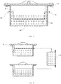
- the present application provides a battery pack system which includes two battery packs as shown in FIG. 4 and a storage tank 3.
- the battery pack includes a battery box 1 and a battery module 2.
- the battery module 2 is disposed in the battery box 1.
- the battery box 1 is further filled with a sealing liquid 14, and the battery module 2 is immersed in the sealing liquid 14.
- the electrode tabs of battery cells are disposed downwards such that the electrode tabs of the battery module 2 are immersed into the sealing liquid 14.
- the sealing liquid 14 in the present embodiment is hydrofluoroether.
- a cooling pipe 11 is disposed in the battery box 1.
- the melting temperature of sidewall of the cooling pipe 11 is at a preset temperature, and the preset temperature is 70 Celsius degree.
- the battery box 1 is provided with an inlet 12.
- the cooling pipe 11 is a blind pipe having one end being open and the other end being sealed. The open end of the cooling pipe 11 is connected to the inlet 12.
- the coolant is ethylene glycol aqueous solution.
- a storage tank 3 is provided outside the battery box 1, and the storage tank 3 is filled with the coolant.
- the storage tank 3 is connected to the battery box 1 through pipeline, and is connected to the cooling pipe 11.
- the present application provides a battery pack system which includes two battery packs as shown in FIG. 5 and a storage tank 3.
- the battery pack includes a battery box 1 and a battery module 2.
- the battery module 2 is disposed in the battery box 1.
- the battery box 1 is further filled with a sealing liquid 14, and the battery module 2 is immersed in the sealing liquid 14.
- the electrode tabs of battery cells are disposed downwards such that the electrode tabs of the battery module 2 are immersed into the sealing liquid 14.
- the sealing liquid 14 in the present embodiment is hydro fluoroether.
- a cooling pipe 11 is disposed in the battery box 1.
- the melting temperature of sidewall of the cooling pipe 11 is at a preset temperature, and the preset temperature is 100 Celsius degree.
- the battery box 1 is provided with an outlet 13 and an inlet 12.
- the cooling pipe 11 is connected to the outlet 13 and the inlet 12.
- the coolant is circulated in the cooling pipe 11 to take away the heat of the sealing liquid 14 to avoid heat accumulation in the battery box1 to cause damage to the battery box 2.
- the coolant is ethylene glycol aqueous solution.
- a storage tank 3 is provided outside the battery box 1, and the storage tank 3 is filled with the coolant.
- the storage tank 3 is connected to the battery box 1 through pipeline, and is connected to the cooling pipe 11.
- the coolant in the storage tank 3 flows along the pipeline, then flows into the cooling pipe 11 through the inlet 12, then flows out from the outlet 13, and finally flows back to the storage tank 3 through the pipeline, to thereby form a complete coolant circulation.
- the present application provides a battery pack system which includes two battery packs as shown in FIG. 5 and a storage tank 3.
- the battery pack includes a battery box 1 and a battery module 2.
- the battery module 2 is disposed in the battery box 1.
- the battery box 1 is further filled with a sealing liquid 14, and the battery module 2 is immersed in the sealing liquid 14.
- the electrode tabs of battery cells are disposed downwards such that the electrode tabs of the battery module 2 are immersed into the sealing liquid 14.
- the sealing liquid 14 in the present embodiment is hydrofluoroether.
- a cooling pipe 11 is disposed in the battery box 1.
- the melting temperature of sidewall of the cooling pipe 11 is at a preset temperature, and the preset temperature is 100 Celsius degree.
- the battery box 1 is provided with an outlet 13 and an inlet 12.
- the cooling pipe 11 is connected to the outlet 13 and the inlet 12.
- the coolant is circulated in the cooling pipe 11 to take away the heat of the sealing liquid 14 to avoid heat accumulation in the battery box1 to cause damage to the battery box 2.
- the coolant is ethylene glycol aqueous solution.
- a storage tank 3 is provided outside the battery box 1, and the storage tank 3 is filled with the coolant.
- the storage tank 3 is connected to the battery box 1 through pipeline, and is connected to the cooling pipe 11.
- the coolant in the storage tank 3 flows along the pipeline, then flows into the cooling pipe 11 through the inlet 12, then flows out from the outlet 13, and finally flows back to the storage tank 3 through the pipeline, to thereby form a complete coolant circulation.
Landscapes
- Chemical & Material Sciences (AREA)
- Chemical Kinetics & Catalysis (AREA)
- Electrochemistry (AREA)
- General Chemical & Material Sciences (AREA)
- Engineering & Computer Science (AREA)
- Manufacturing & Machinery (AREA)
- Materials Engineering (AREA)
- Secondary Cells (AREA)
- Battery Mounting, Suspending (AREA)
Applications Claiming Priority (1)
| Application Number | Priority Date | Filing Date | Title |
|---|---|---|---|
| PCT/CN2015/084457 WO2017011974A1 (fr) | 2015-07-20 | 2015-07-20 | Bloc-batterie et système de bloc-batterie |
Publications (3)
| Publication Number | Publication Date |
|---|---|
| EP3306737A1 true EP3306737A1 (fr) | 2018-04-11 |
| EP3306737A4 EP3306737A4 (fr) | 2018-06-13 |
| EP3306737B1 EP3306737B1 (fr) | 2019-05-15 |
Family
ID=57833625
Family Applications (1)
| Application Number | Title | Priority Date | Filing Date |
|---|---|---|---|
| EP15898530.9A Active EP3306737B1 (fr) | 2015-07-20 | 2015-07-20 | Bloc-batterie et système de bloc-batterie |
Country Status (4)
| Country | Link |
|---|---|
| US (1) | US20180191038A1 (fr) |
| EP (1) | EP3306737B1 (fr) |
| CN (1) | CN107710493B (fr) |
| WO (1) | WO2017011974A1 (fr) |
Cited By (1)
| Publication number | Priority date | Publication date | Assignee | Title |
|---|---|---|---|---|
| US12278356B2 (en) | 2019-05-14 | 2025-04-15 | Lg Energy Solution, Ltd. | Battery module and battery pack including the same |
Families Citing this family (30)
| Publication number | Priority date | Publication date | Assignee | Title |
|---|---|---|---|---|
| CN106816668A (zh) * | 2017-03-22 | 2017-06-09 | 北京航盛新能科技有限公司 | 一种动力电池热失控降温灭火液冷装置、监控系统及方法 |
| CA3054393C (fr) * | 2017-04-05 | 2021-11-16 | Siemens Aktiengesellschaft | Systeme de refroidissement et methode ayant un tuyau d'entree commun et un tuyau de sortie commun ayant des points de fusion differents |
| US10668832B2 (en) * | 2017-09-12 | 2020-06-02 | Chongqing Jinkang New Energy Vehicle Co., Ltd. | Temperature control apparatus for electric vehicle battery packs |
| JP2022508811A (ja) * | 2018-10-15 | 2022-01-19 | エレクトリック パワー システムズ, インコーポレイテッド | 冷却剤分散によるバッテリの熱的管理 |
| EP3898878A4 (fr) | 2018-12-21 | 2022-08-24 | Honeywell International Inc. | Compositions azéotropes ou du type azéotrope du 1,2,2-trifluoro-1-trifluorométhylcyclobutane (tfmcb) et applications associées |
| EP3742541A1 (fr) * | 2019-05-21 | 2020-11-25 | 3M Innovative Properties Company | Système de gestion thermique pour cellules de batterie |
| CN110335973B (zh) * | 2019-06-07 | 2022-04-15 | 扬顶(天津)科技有限公司 | 一种固态电池用的防火装置 |
| CN110335975A (zh) * | 2019-07-10 | 2019-10-15 | 扬州道爵新能源发展有限公司 | 一种电动汽车电池包 |
| CN110609235A (zh) * | 2019-10-14 | 2019-12-24 | 中国民用航空飞行学院 | 基于光纤探测技术的锂电池热安全监控系统 |
| DE102020104891A1 (de) | 2020-02-25 | 2021-08-26 | Bayerische Motoren Werke Aktiengesellschaft | Kühleinrichtung zum Kühlen eines Energiespeichers eines Kraftfahrzeugs sowie Kraftfahrzeug |
| CN111640891A (zh) * | 2020-06-03 | 2020-09-08 | 中国电力科学研究院有限公司 | 一种锂离子电池装置及其制备方法 |
| US11949083B2 (en) * | 2020-06-11 | 2024-04-02 | Global Graphene Group, Inc. | Battery module or pack with a distributed cooling and fire protection system and method of operating same |
| CN112002846B (zh) * | 2020-09-08 | 2022-03-11 | 北京未来智酷汽车科技有限公司 | 电池容器及其电池的灭火方法、车辆 |
| CN112290110A (zh) * | 2020-11-05 | 2021-01-29 | 中国石油大学(华东) | 一种耦合热管理及热失控抑制的电池安全系统 |
| CN112618997A (zh) * | 2020-12-30 | 2021-04-09 | 蜂巢能源科技有限公司 | 电池储能系统的液冷消防系统及消防方法 |
| CN113217682B (zh) * | 2021-02-08 | 2025-05-02 | 青岛能蜂电气有限公司 | 一种自反馈调节的阀门装置及灭火设备 |
| DE102021108986B3 (de) | 2021-04-12 | 2022-07-28 | Bayerische Motoren Werke Aktiengesellschaft | Elektrischer Energiespeicher für ein Kraftfahrzeug |
| CN113018730A (zh) * | 2021-04-23 | 2021-06-25 | 江铃汽车股份有限公司 | 动力电池灭火装置及其电池箱体和电池包 |
| KR102956952B1 (ko) * | 2021-07-28 | 2026-04-24 | 에스케이온 주식회사 | 배터리 랙 |
| KR102699106B1 (ko) * | 2021-09-06 | 2024-08-27 | 한국항공우주연구원 | 에너지 저장장치의 열확산 지연과 열폭주 방지를 위한 지지대 |
| US11981230B2 (en) * | 2021-12-14 | 2024-05-14 | Caterpillar Inc. | Method to control multiple parallel battery packs |
| IT202200003902A1 (it) * | 2022-03-02 | 2023-09-02 | Iveco Spa | Sistema di sicurezza per pacco batterie di propulsione veicolare |
| IT202200003932A1 (it) * | 2022-03-02 | 2023-09-02 | Iveco Spa | Sistema di sicurezza per pacco batterie di propulsione veicolare |
| DE102022108830A1 (de) | 2022-04-12 | 2023-10-12 | Dr. Ing. H.C. F. Porsche Aktiengesellschaft | Kfz-Traktionsbatterie-Anordnung |
| CN116995313A (zh) * | 2022-04-26 | 2023-11-03 | 西胜国际股份有限公司 | 具有热管理结构的电池模块 |
| CN116995341A (zh) * | 2022-04-26 | 2023-11-03 | 西胜国际股份有限公司 | 具有阻燃结构的电池模块 |
| CN114849119B (zh) * | 2022-05-30 | 2025-11-14 | 吉林国鑫碳纤维有限公司 | 一种防止碳纤维氧化炉着火后火势蔓延的装置 |
| CN114944524A (zh) * | 2022-06-30 | 2022-08-26 | 齐鲁中科光物理与工程技术研究院 | 一种浸没式液冷电池箱及其制备方法 |
| CN115360467A (zh) * | 2022-09-23 | 2022-11-18 | 四川长虹电源有限责任公司 | 电池系统 |
| CN115764050B (zh) * | 2022-10-21 | 2026-02-03 | 华南理工大学 | 一种基于电池全区域散热的浸没冷却系统 |
Family Cites Families (15)
| Publication number | Priority date | Publication date | Assignee | Title |
|---|---|---|---|---|
| JP4435327B2 (ja) * | 1999-05-14 | 2010-03-17 | パナソニック株式会社 | 組電池の充電制御装置 |
| JP4525695B2 (ja) * | 2007-03-30 | 2010-08-18 | トヨタ自動車株式会社 | 蓄電装置 |
| DE102007021309A1 (de) * | 2007-05-07 | 2008-11-13 | Valeo Klimasysteme Gmbh | Antriebsbatteriebaugruppe eines Elktro-, Brennstoffzellen- oder Hybridfahrzeugs |
| DE102007045183A1 (de) * | 2007-09-21 | 2009-04-02 | Robert Bosch Gmbh | Temperierte Batterieeinrichtung und Verfahren hierzu |
| JP4815026B2 (ja) * | 2009-07-17 | 2011-11-16 | パナソニック株式会社 | 電池モジュールとそれを用いた電池パック |
| CN102019651A (zh) * | 2009-09-11 | 2011-04-20 | 苏州红枫风电模具有限公司 | 风轮机叶片模具加热系统 |
| US9093726B2 (en) * | 2009-09-12 | 2015-07-28 | Tesla Motors, Inc. | Active thermal runaway mitigation system for use within a battery pack |
| CN101717878A (zh) * | 2009-12-10 | 2010-06-02 | 北京有色金属研究总院 | 一种耐海水冲刷腐蚀的铜镍合金及其管材和制备方法 |
| JP5804323B2 (ja) * | 2011-01-07 | 2015-11-04 | 株式会社Gsユアサ | 蓄電素子及び蓄電装置 |
| CN202662693U (zh) * | 2012-06-26 | 2013-01-09 | 微宏动力系统(湖州)有限公司 | 防爆电池组 |
| CN103682511B (zh) * | 2012-09-13 | 2017-03-29 | 微宏动力系统(湖州)有限公司 | 电动汽车 |
| US9912021B2 (en) * | 2013-05-17 | 2018-03-06 | Hamilton Sundstrand Corporation | Electrical storage device thermal management systems |
| US9515357B2 (en) * | 2014-01-15 | 2016-12-06 | Ford Global Technologies, Llc | Battery thermal management system for electrified vehicle |
| CN103985921B (zh) * | 2014-05-15 | 2016-02-24 | 华霆(合肥)动力技术有限公司 | 一种增压液冷抑制电池热失稳系统 |
| CN203941961U (zh) * | 2014-06-30 | 2014-11-12 | 河南新太行电源有限公司 | 一种电源箱体上的防爆装置 |
-
2015
- 2015-07-20 EP EP15898530.9A patent/EP3306737B1/fr active Active
- 2015-07-20 CN CN201580081272.1A patent/CN107710493B/zh active Active
- 2015-07-20 WO PCT/CN2015/084457 patent/WO2017011974A1/fr not_active Ceased
- 2015-07-20 US US15/741,272 patent/US20180191038A1/en not_active Abandoned
Cited By (2)
| Publication number | Priority date | Publication date | Assignee | Title |
|---|---|---|---|---|
| US12278356B2 (en) | 2019-05-14 | 2025-04-15 | Lg Energy Solution, Ltd. | Battery module and battery pack including the same |
| US12614780B2 (en) | 2019-05-14 | 2026-04-28 | Lg Energy Solution, Ltd. | Battery module and battery pack including the same |
Also Published As
| Publication number | Publication date |
|---|---|
| EP3306737B1 (fr) | 2019-05-15 |
| CN107710493B (zh) | 2020-04-17 |
| CN107710493A (zh) | 2018-02-16 |
| US20180191038A1 (en) | 2018-07-05 |
| EP3306737A4 (fr) | 2018-06-13 |
| WO2017011974A1 (fr) | 2017-01-26 |
Similar Documents
| Publication | Publication Date | Title |
|---|---|---|
| EP3306737B1 (fr) | Bloc-batterie et système de bloc-batterie | |
| CN107851861B (zh) | 一种电池组 | |
| EP2997623B1 (fr) | Gestion thermique active et prévention d'un emballement thermique pour bloc de batteries au lithium-ion à haute densité d'énergie | |
| EP3322015B1 (fr) | Batterie | |
| KR20220051758A (ko) | 효율과 안전성이 향상된 배터리 열관리장치 및 관리방법 | |
| KR102404099B1 (ko) | 전기소자용 다중채널 낙수냉각방식의 열제어장치 | |
| US12407041B2 (en) | Immersion cooling battery system integrated with enclosure | |
| CN108400408A (zh) | 一种具有阻燃的车用动力电池多通道液冷装置 | |
| CN105206895A (zh) | 电池组的冷却方法及带有冷却装置的电池组 | |
| BR112021007085A2 (pt) | gestão térmica de dispositivos de armazenamento eletroquímicos | |
| KR102552454B1 (ko) | 에너지저장장치(ess) 화재예방 시스템 | |
| KR102786238B1 (ko) | 수냉식 에너지저장장치의 냉각액을 이용한 침지식 배터리 소화 시스템 및 그 소화 방법 | |
| CN104466276A (zh) | 锂电池的保护装置及保护方法 | |
| US20250062427A1 (en) | Non-destructive battery fire suppression | |
| US20150288037A1 (en) | Insulating liquid immersed battery | |
| CN111384341A (zh) | 一种具有防火功能的锂电池箱及其使用方法 | |
| Ping et al. | A novel dual-purpose thermal runaway propagation mitigation system using a liquid cooling pipe with aperture sealed by films | |
| US11171383B1 (en) | Battery module | |
| KR102308160B1 (ko) | 배터리팩 | |
| KR102818053B1 (ko) | 액침 냉각 방식 에너지 저장 장치 함체 | |
| CN216624401U (zh) | 液冷储能系统 | |
| KR102659406B1 (ko) | 배터리모듈 화재 소화가 가능한 전산실용 에너지 저장장치 | |
| KR20260030659A (ko) | 수냉식 에너지저장장치의 냉각액을 이용한 침지식 배터리 소화 시스템 및 그 소화방법 | |
| Mo et al. | Experiments on the effects of immersion cooling on lithium-ion battery module and mitigating battery thermal runaway | |
| Wahab et al. | Fire-Safe Lithium-Ion Batteries with Forced Immersion Cooling for Electric Vehicles and Next-Generation Energy Systems |
Legal Events
| Date | Code | Title | Description |
|---|---|---|---|
| STAA | Information on the status of an ep patent application or granted ep patent |
Free format text: STATUS: THE INTERNATIONAL PUBLICATION HAS BEEN MADE |
|
| PUAI | Public reference made under article 153(3) epc to a published international application that has entered the european phase |
Free format text: ORIGINAL CODE: 0009012 |
|
| STAA | Information on the status of an ep patent application or granted ep patent |
Free format text: STATUS: REQUEST FOR EXAMINATION WAS MADE |
|
| 17P | Request for examination filed |
Effective date: 20180102 |
|
| AK | Designated contracting states |
Kind code of ref document: A1 Designated state(s): AL AT BE BG CH CY CZ DE DK EE ES FI FR GB GR HR HU IE IS IT LI LT LU LV MC MK MT NL NO PL PT RO RS SE SI SK SM TR |
|
| AX | Request for extension of the european patent |
Extension state: BA ME |
|
| A4 | Supplementary search report drawn up and despatched |
Effective date: 20180511 |
|
| RIC1 | Information provided on ipc code assigned before grant |
Ipc: H01M 10/613 20140101AFI20180504BHEP Ipc: H01M 10/6567 20140101ALI20180504BHEP Ipc: H01M 10/6569 20140101ALI20180504BHEP Ipc: H01M 10/656 20140101ALI20180504BHEP |
|
| STAA | Information on the status of an ep patent application or granted ep patent |
Free format text: STATUS: EXAMINATION IS IN PROGRESS |
|
| RIN1 | Information on inventor provided before grant (corrected) |
Inventor name: LI, HUI Inventor name: TONG, ZHIMING Inventor name: FU, LINGYAN Inventor name: LI, XIANG |
|
| 17Q | First examination report despatched |
Effective date: 20180613 |
|
| DAV | Request for validation of the european patent (deleted) | ||
| DAX | Request for extension of the european patent (deleted) | ||
| GRAP | Despatch of communication of intention to grant a patent |
Free format text: ORIGINAL CODE: EPIDOSNIGR1 |
|
| STAA | Information on the status of an ep patent application or granted ep patent |
Free format text: STATUS: GRANT OF PATENT IS INTENDED |
|
| INTG | Intention to grant announced |
Effective date: 20190108 |
|
| GRAS | Grant fee paid |
Free format text: ORIGINAL CODE: EPIDOSNIGR3 |
|
| GRAA | (expected) grant |
Free format text: ORIGINAL CODE: 0009210 |
|
| STAA | Information on the status of an ep patent application or granted ep patent |
Free format text: STATUS: THE PATENT HAS BEEN GRANTED |
|
| AK | Designated contracting states |
Kind code of ref document: B1 Designated state(s): AL AT BE BG CH CY CZ DE DK EE ES FI FR GB GR HR HU IE IS IT LI LT LU LV MC MK MT NL NO PL PT RO RS SE SI SK SM TR |
|
| REG | Reference to a national code |
Ref country code: CH Ref legal event code: EP |
|
| REG | Reference to a national code |
Ref country code: DE Ref legal event code: R096 Ref document number: 602015030575 Country of ref document: DE |
|
| REG | Reference to a national code |
Ref country code: IE Ref legal event code: FG4D |
|
| REG | Reference to a national code |
Ref country code: NL Ref legal event code: MP Effective date: 20190515 |
|
| REG | Reference to a national code |
Ref country code: LT Ref legal event code: MG4D |
|
| PG25 | Lapsed in a contracting state [announced via postgrant information from national office to epo] |
Ref country code: AL Free format text: LAPSE BECAUSE OF FAILURE TO SUBMIT A TRANSLATION OF THE DESCRIPTION OR TO PAY THE FEE WITHIN THE PRESCRIBED TIME-LIMIT Effective date: 20190515 Ref country code: PT Free format text: LAPSE BECAUSE OF FAILURE TO SUBMIT A TRANSLATION OF THE DESCRIPTION OR TO PAY THE FEE WITHIN THE PRESCRIBED TIME-LIMIT Effective date: 20190915 Ref country code: ES Free format text: LAPSE BECAUSE OF FAILURE TO SUBMIT A TRANSLATION OF THE DESCRIPTION OR TO PAY THE FEE WITHIN THE PRESCRIBED TIME-LIMIT Effective date: 20190515 Ref country code: NL Free format text: LAPSE BECAUSE OF FAILURE TO SUBMIT A TRANSLATION OF THE DESCRIPTION OR TO PAY THE FEE WITHIN THE PRESCRIBED TIME-LIMIT Effective date: 20190515 Ref country code: NO Free format text: LAPSE BECAUSE OF FAILURE TO SUBMIT A TRANSLATION OF THE DESCRIPTION OR TO PAY THE FEE WITHIN THE PRESCRIBED TIME-LIMIT Effective date: 20190815 Ref country code: LT Free format text: LAPSE BECAUSE OF FAILURE TO SUBMIT A TRANSLATION OF THE DESCRIPTION OR TO PAY THE FEE WITHIN THE PRESCRIBED TIME-LIMIT Effective date: 20190515 Ref country code: FI Free format text: LAPSE BECAUSE OF FAILURE TO SUBMIT A TRANSLATION OF THE DESCRIPTION OR TO PAY THE FEE WITHIN THE PRESCRIBED TIME-LIMIT Effective date: 20190515 Ref country code: SE Free format text: LAPSE BECAUSE OF FAILURE TO SUBMIT A TRANSLATION OF THE DESCRIPTION OR TO PAY THE FEE WITHIN THE PRESCRIBED TIME-LIMIT Effective date: 20190515 Ref country code: HR Free format text: LAPSE BECAUSE OF FAILURE TO SUBMIT A TRANSLATION OF THE DESCRIPTION OR TO PAY THE FEE WITHIN THE PRESCRIBED TIME-LIMIT Effective date: 20190515 |
|
| PG25 | Lapsed in a contracting state [announced via postgrant information from national office to epo] |
Ref country code: RS Free format text: LAPSE BECAUSE OF FAILURE TO SUBMIT A TRANSLATION OF THE DESCRIPTION OR TO PAY THE FEE WITHIN THE PRESCRIBED TIME-LIMIT Effective date: 20190515 Ref country code: LV Free format text: LAPSE BECAUSE OF FAILURE TO SUBMIT A TRANSLATION OF THE DESCRIPTION OR TO PAY THE FEE WITHIN THE PRESCRIBED TIME-LIMIT Effective date: 20190515 Ref country code: GR Free format text: LAPSE BECAUSE OF FAILURE TO SUBMIT A TRANSLATION OF THE DESCRIPTION OR TO PAY THE FEE WITHIN THE PRESCRIBED TIME-LIMIT Effective date: 20190816 Ref country code: BG Free format text: LAPSE BECAUSE OF FAILURE TO SUBMIT A TRANSLATION OF THE DESCRIPTION OR TO PAY THE FEE WITHIN THE PRESCRIBED TIME-LIMIT Effective date: 20190815 |
|
| REG | Reference to a national code |
Ref country code: AT Ref legal event code: MK05 Ref document number: 1134497 Country of ref document: AT Kind code of ref document: T Effective date: 20190515 |
|
| PG25 | Lapsed in a contracting state [announced via postgrant information from national office to epo] |
Ref country code: AT Free format text: LAPSE BECAUSE OF FAILURE TO SUBMIT A TRANSLATION OF THE DESCRIPTION OR TO PAY THE FEE WITHIN THE PRESCRIBED TIME-LIMIT Effective date: 20190515 Ref country code: DK Free format text: LAPSE BECAUSE OF FAILURE TO SUBMIT A TRANSLATION OF THE DESCRIPTION OR TO PAY THE FEE WITHIN THE PRESCRIBED TIME-LIMIT Effective date: 20190515 Ref country code: CZ Free format text: LAPSE BECAUSE OF FAILURE TO SUBMIT A TRANSLATION OF THE DESCRIPTION OR TO PAY THE FEE WITHIN THE PRESCRIBED TIME-LIMIT Effective date: 20190515 Ref country code: EE Free format text: LAPSE BECAUSE OF FAILURE TO SUBMIT A TRANSLATION OF THE DESCRIPTION OR TO PAY THE FEE WITHIN THE PRESCRIBED TIME-LIMIT Effective date: 20190515 Ref country code: SK Free format text: LAPSE BECAUSE OF FAILURE TO SUBMIT A TRANSLATION OF THE DESCRIPTION OR TO PAY THE FEE WITHIN THE PRESCRIBED TIME-LIMIT Effective date: 20190515 |
|
| REG | Reference to a national code |
Ref country code: DE Ref legal event code: R097 Ref document number: 602015030575 Country of ref document: DE |
|
| PG25 | Lapsed in a contracting state [announced via postgrant information from national office to epo] |
Ref country code: MC Free format text: LAPSE BECAUSE OF FAILURE TO SUBMIT A TRANSLATION OF THE DESCRIPTION OR TO PAY THE FEE WITHIN THE PRESCRIBED TIME-LIMIT Effective date: 20190515 Ref country code: IT Free format text: LAPSE BECAUSE OF FAILURE TO SUBMIT A TRANSLATION OF THE DESCRIPTION OR TO PAY THE FEE WITHIN THE PRESCRIBED TIME-LIMIT Effective date: 20190515 Ref country code: SM Free format text: LAPSE BECAUSE OF FAILURE TO SUBMIT A TRANSLATION OF THE DESCRIPTION OR TO PAY THE FEE WITHIN THE PRESCRIBED TIME-LIMIT Effective date: 20190515 |
|
| REG | Reference to a national code |
Ref country code: CH Ref legal event code: PL |
|
| PLBE | No opposition filed within time limit |
Free format text: ORIGINAL CODE: 0009261 |
|
| STAA | Information on the status of an ep patent application or granted ep patent |
Free format text: STATUS: NO OPPOSITION FILED WITHIN TIME LIMIT |
|
| PG25 | Lapsed in a contracting state [announced via postgrant information from national office to epo] |
Ref country code: TR Free format text: LAPSE BECAUSE OF FAILURE TO SUBMIT A TRANSLATION OF THE DESCRIPTION OR TO PAY THE FEE WITHIN THE PRESCRIBED TIME-LIMIT Effective date: 20190515 |
|
| REG | Reference to a national code |
Ref country code: BE Ref legal event code: MM Effective date: 20190731 |
|
| 26N | No opposition filed |
Effective date: 20200218 |
|
| PG25 | Lapsed in a contracting state [announced via postgrant information from national office to epo] |
Ref country code: PL Free format text: LAPSE BECAUSE OF FAILURE TO SUBMIT A TRANSLATION OF THE DESCRIPTION OR TO PAY THE FEE WITHIN THE PRESCRIBED TIME-LIMIT Effective date: 20190515 |
|
| PG25 | Lapsed in a contracting state [announced via postgrant information from national office to epo] |
Ref country code: BE Free format text: LAPSE BECAUSE OF NON-PAYMENT OF DUE FEES Effective date: 20190731 Ref country code: SI Free format text: LAPSE BECAUSE OF FAILURE TO SUBMIT A TRANSLATION OF THE DESCRIPTION OR TO PAY THE FEE WITHIN THE PRESCRIBED TIME-LIMIT Effective date: 20190515 Ref country code: LI Free format text: LAPSE BECAUSE OF NON-PAYMENT OF DUE FEES Effective date: 20190731 Ref country code: CH Free format text: LAPSE BECAUSE OF NON-PAYMENT OF DUE FEES Effective date: 20190731 Ref country code: LU Free format text: LAPSE BECAUSE OF NON-PAYMENT OF DUE FEES Effective date: 20190720 |
|
| PG25 | Lapsed in a contracting state [announced via postgrant information from national office to epo] |
Ref country code: FR Free format text: LAPSE BECAUSE OF NON-PAYMENT OF DUE FEES Effective date: 20190731 |
|
| PG25 | Lapsed in a contracting state [announced via postgrant information from national office to epo] |
Ref country code: IE Free format text: LAPSE BECAUSE OF NON-PAYMENT OF DUE FEES Effective date: 20190720 |
|
| PG25 | Lapsed in a contracting state [announced via postgrant information from national office to epo] |
Ref country code: RO Free format text: LAPSE BECAUSE OF FAILURE TO SUBMIT A TRANSLATION OF THE DESCRIPTION OR TO PAY THE FEE WITHIN THE PRESCRIBED TIME-LIMIT Effective date: 20190515 |
|
| PG25 | Lapsed in a contracting state [announced via postgrant information from national office to epo] |
Ref country code: CY Free format text: LAPSE BECAUSE OF FAILURE TO SUBMIT A TRANSLATION OF THE DESCRIPTION OR TO PAY THE FEE WITHIN THE PRESCRIBED TIME-LIMIT Effective date: 20190515 |
|
| PG25 | Lapsed in a contracting state [announced via postgrant information from national office to epo] |
Ref country code: IS Free format text: LAPSE BECAUSE OF FAILURE TO SUBMIT A TRANSLATION OF THE DESCRIPTION OR TO PAY THE FEE WITHIN THE PRESCRIBED TIME-LIMIT Effective date: 20190915 |
|
| PG25 | Lapsed in a contracting state [announced via postgrant information from national office to epo] |
Ref country code: MT Free format text: LAPSE BECAUSE OF FAILURE TO SUBMIT A TRANSLATION OF THE DESCRIPTION OR TO PAY THE FEE WITHIN THE PRESCRIBED TIME-LIMIT Effective date: 20190515 Ref country code: HU Free format text: LAPSE BECAUSE OF FAILURE TO SUBMIT A TRANSLATION OF THE DESCRIPTION OR TO PAY THE FEE WITHIN THE PRESCRIBED TIME-LIMIT; INVALID AB INITIO Effective date: 20150720 |
|
| PG25 | Lapsed in a contracting state [announced via postgrant information from national office to epo] |
Ref country code: MK Free format text: LAPSE BECAUSE OF FAILURE TO SUBMIT A TRANSLATION OF THE DESCRIPTION OR TO PAY THE FEE WITHIN THE PRESCRIBED TIME-LIMIT Effective date: 20190515 |
|
| PGFP | Annual fee paid to national office [announced via postgrant information from national office to epo] |
Ref country code: GB Payment date: 20250529 Year of fee payment: 11 |
|
| PGFP | Annual fee paid to national office [announced via postgrant information from national office to epo] |
Ref country code: DE Payment date: 20250711 Year of fee payment: 11 |