EP3306785A1 - Permanentmagnetmotorrotor und permanentmagnetsynchronmotor - Google Patents
Permanentmagnetmotorrotor und permanentmagnetsynchronmotor Download PDFInfo
- Publication number
- EP3306785A1 EP3306785A1 EP16802504.7A EP16802504A EP3306785A1 EP 3306785 A1 EP3306785 A1 EP 3306785A1 EP 16802504 A EP16802504 A EP 16802504A EP 3306785 A1 EP3306785 A1 EP 3306785A1
- Authority
- EP
- European Patent Office
- Prior art keywords
- permanent magnet
- main
- pole
- auxiliary
- rotor
- Prior art date
- Legal status (The legal status is an assumption and is not a legal conclusion. Google has not performed a legal analysis and makes no representation as to the accuracy of the status listed.)
- Granted
Links
Images


Classifications
-
- H—ELECTRICITY
- H02—GENERATION; CONVERSION OR DISTRIBUTION OF ELECTRIC POWER
- H02K—DYNAMO-ELECTRIC MACHINES
- H02K1/00—Details of the magnetic circuit
- H02K1/06—Details of the magnetic circuit characterised by the shape, form or construction
- H02K1/22—Rotating parts of the magnetic circuit
- H02K1/27—Rotor cores with permanent magnets
- H02K1/2706—Inner rotors
- H02K1/272—Inner rotors the magnetisation axis of the magnets being perpendicular to the rotor axis
- H02K1/274—Inner rotors the magnetisation axis of the magnets being perpendicular to the rotor axis the rotor consisting of two or more circumferentially positioned magnets
- H02K1/2753—Inner rotors the magnetisation axis of the magnets being perpendicular to the rotor axis the rotor consisting of two or more circumferentially positioned magnets the rotor consisting of magnets or groups of magnets arranged with alternating polarity
- H02K1/276—Magnets embedded in the magnetic core, e.g. interior permanent magnets [IPM]
- H02K1/2766—Magnets embedded in the magnetic core, e.g. interior permanent magnets [IPM] having a flux concentration effect
- H02K1/2773—Magnets embedded in the magnetic core, e.g. interior permanent magnets [IPM] having a flux concentration effect consisting of tangentially magnetized radial magnets
-
- H—ELECTRICITY
- H02—GENERATION; CONVERSION OR DISTRIBUTION OF ELECTRIC POWER
- H02K—DYNAMO-ELECTRIC MACHINES
- H02K1/00—Details of the magnetic circuit
- H02K1/06—Details of the magnetic circuit characterised by the shape, form or construction
- H02K1/22—Rotating parts of the magnetic circuit
- H02K1/27—Rotor cores with permanent magnets
- H02K1/2706—Inner rotors
- H02K1/272—Inner rotors the magnetisation axis of the magnets being perpendicular to the rotor axis
- H02K1/274—Inner rotors the magnetisation axis of the magnets being perpendicular to the rotor axis the rotor consisting of two or more circumferentially positioned magnets
- H02K1/2753—Inner rotors the magnetisation axis of the magnets being perpendicular to the rotor axis the rotor consisting of two or more circumferentially positioned magnets the rotor consisting of magnets or groups of magnets arranged with alternating polarity
- H02K1/276—Magnets embedded in the magnetic core, e.g. interior permanent magnets [IPM]
- H02K1/2766—Magnets embedded in the magnetic core, e.g. interior permanent magnets [IPM] having a flux concentration effect
-
- H—ELECTRICITY
- H02—GENERATION; CONVERSION OR DISTRIBUTION OF ELECTRIC POWER
- H02K—DYNAMO-ELECTRIC MACHINES
- H02K21/00—Synchronous motors having permanent magnets; Synchronous generators having permanent magnets
- H02K21/12—Synchronous motors having permanent magnets; Synchronous generators having permanent magnets with stationary armatures and rotating magnets
- H02K21/14—Synchronous motors having permanent magnets; Synchronous generators having permanent magnets with stationary armatures and rotating magnets with magnets rotating within the armatures
-
- H—ELECTRICITY
- H02—GENERATION; CONVERSION OR DISTRIBUTION OF ELECTRIC POWER
- H02K—DYNAMO-ELECTRIC MACHINES
- H02K2201/00—Specific aspects not provided for in the other groups of this subclass relating to the magnetic circuits
Definitions
- the present disclosure relates to a motor device, and more particularly, to a tangentially magnetized permanent magnet motor rotor, and a permanent magnet synchronous motor having the permanent magnet motor rotor.
- the motor with tangentially magnetized permanent magnets provides a magnetic congregate effect, as compared with the magnetic motor with radially magnetized permanent magnets, a higher air-gap magnetic flux density is generated, thereby the motor with tangentially magnetized permanent magnets has a higher ratio of the torque to the current and a higher ratio of the torque to the volume. Therefore, the motor with tangentially magnetized permanent magnets has been more and more used in applications such as the servo system, electric traction, office automation and domestic appliances.
- both surfaces of a single permanent magnet embedded in the tangentially magnetized permanent magnet motor are configured to provide an air-gap magnetic flux simultaneously, and the magnetic circuit has a parallel structure, which leads to a lower operating point as compared with radially magnetized permanent magnet motor, and may be prone to decrease the efficiency of the tangentially magnetized permanent magnet motor. Even more, there is a risk of demagnetization of the tangentially magnetized permanent magnet motor under a rugged environment, which may result in that the tangentially magnetized permanent magnet motor is unable to operate.
- a permanent magnet motor rotor comprises:
- the auxiliary permanent magnet is located at a symmetrical centerline between any two adjacent main-pole permanent magnets.
- the auxiliary permanent magnet is located at a position offset from a symmetrical centerline between any two main-pole permanent magnets, and the auxiliary permanent magnet is offset toward an adjacent main-pole permanent magnet having an opposite magnetic pole from that of the auxiliary permanent magnet.
- the coercivity of the auxiliary permanent magnet is less than the coercivity of the main-pole permanent magnet.
- the width of the auxiliary permanent magnet in a circumferential direction of the rotor core is less than the width of the main-pole permanent magnet in a circumferential direction of the rotor core.
- the length of the auxiliary permanent magnet in a radial direction of the rotor core is less than the le ngth of the main-pole permanent magnet in a radial direction of the rotor core.
- the number of the main-pole permanent magnets is larger than or equal to four.
- any pair of adjacent main-pole permanent magnet and auxiliary permanent magnet are arranged in parallel, and the surface of the main-pole permanent magnet is attached to the surface of the auxiliary permanent magnet having an opposite magnetic pole from that of the main-pole permanent magnet.
- any pair of adjacent main-pole permanent magnet and the auxiliary permanent magnet are integrated.
- a permanent magnet synchronous motor comprising a stator and a rotor, the stator being disposed outside the rotor, wherein, the rotor is the permanent magnet motor rotor as described in any one of the aforementioned embodiments.
- the permanent magnet motor rotor and the permanent magnet synchronous motor of the present disclosure have a simple and re asonable structure, by arranging an auxiliary permanent magnet between any two adjacent main-pole permanent magnets, a part of the magnetic lines of the main-pole permanent magnet connect with the magnetic lines of the auxiliary permanent magnet in series, and then enter into th e air-gap, the operating point of the main-pole permanent magnet is remarkably raised, the output torque of the permanent magnet synchronous motor is improved. Meanwhile, because of the increase of the operating point of the main-pole permanent magnet, the demagnetization resistance capacity of the main-pole permanent magnet is improved, and the demagnetization risk is reduced.
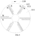
- a permanent magnet motor rotor 110 includes a rotor core 111, tangentially magnetized main-pole permanent magnets 112 and tangentially magnetized auxiliary permanent magnets 113.
- An even number of receiving grooves are disposed in the rotor core 111, and the even number of the receiving grooves are arranged uniformly in a circumferential direction of the rotor core 111, and each receiving groove is disposed in a radial direction of the rotor core 111.
- the number of the receiving grooves is equal to the number of the poles of the permanent magnet synchronous motor, and the number of the main-pole permanent magnets is equal to the number of the receiving grooves.
- the permanent magnet synchronous motor 100 has an even number of poles, and the number of main-pole permanent magnets is an even number, and the even number of main-pole permanent magnets 112 are distributed uniformly in the circumferential direction of the rotor core 111.
- Each main-pole permanent magnet 112 is disposed in a receiving groove respectively, and the closest surfaces of any two adjacent main-pole permanent magnets 112 have same magnetic poles.
- Each receiving groove receives a main-pole permanent magnet 112, so that both surfaces of the main-pole permanent magnet 112 are able to provide air-gap magnetic flux, which increases the air-gap magnetic flux of the permanent magnet synchronous motor 100, and improves the utilization rate of the air-gapmagneticflux.
- any two adjacent main-pole permanent magnets 112 have same magnetic poles, that is, an N-pole of one main-pole permanent magnet 112 faces an N-pole of another adjacent main-pole permanent magnet 112, and an S-pole of one main-pole permanent magnet 112 faces an S-pole of the other adjacent main-pole permanent magnet 112, which ensures that the number of the poles of the permanent magnet synchronous motor 100 is equal to the number of the main-pole permanent magnets 112.
- main-pole permanent magnets 112 By respectively installing an even number of main-pole permanent magnets 112 into the receiving grooves arranged uniformly, it is ensured that the magnetic repulsion force on the main-pole permanent magnet 112 is balanced, and the number of the poles of the permanent magnet synchronous motor 100 is equal to the number of the main-pole permanent magnets 112.
- the auxiliary permanent magnet 113 is located between any two adjacent main-pole permanent magnets 112, and the auxiliary permanent magnet 113 is arranged in a radial direction of the rotor core 111.
- the number of the auxiliary permanent magnets 113 is equal to the number of the main-pole permanent magnets 112, meanwhile one auxiliary permanent magnet 113 is provided between every two adjacent main-pole permanent magnets 112.
- the main-pole permanent magnets 112 and the auxiliary permanent magnets 113 are tangentially magnetized, so that the permanent magnet synchronous motor 100 can generate a higher air-gap magnetic flux, and have a higher ratio of the torque to the current and a higher ratio of the torque to the volume.
- the main-pole permanent magnets 112 and the auxiliary permanent magnets 113 are placed along the radial direction of the rotor core 111, and by arranging a tangentially magnetized auxiliary permanent magnet 113 between any two adjacent main-pole permanent magnets 112, a part of the magnetic lines of the main-pole permanent magnet 112 connect with the magnetic lines of the auxiliary permanent magnet 113 in series, and then enter into the air-gap, thus the operating point of the main-pole permanent magnet 112 is remarkably raised, and the permanent magnet motor rotor 110 generates more flux linkage at the side of the stator 120, thereby the utilization rate of the air-gap magnetic flux is increased, and the output torque and the efficiency of the permanent magnet synchronous motor 100 are improved.
- the magnetic circuit has a parallel structure, so that the tangentially magnetized permanent magnet motor has a lower operating point as compared with the radially magnetized permanent magnet motor, which may be prone to decrease the efficiency of the tangentially magnetized permanent magnet motor. Even more, there is a risk of demagnetization of the tangentially magnetized permanent magnet motor, which may result in that the tangential permanent magnet motor is unable to operate.
- an auxiliary permanent magnet 113 is installed between any two main-pole permanent magnets 112 in the perm anent magnet motor rotor, a part of the magnetic lines of the main-pole permanent magnet 112 connect with the magnetic lines of the auxiliary permanent magnet 113 in series , and then enter into the air-gap, thus the operating point of the main-pole permanent magnet 112 is remarkably raised, and the output torque of the permanent magnet synchronous motor 100 is increased. Meanwhile, because of the increase of the operating point of the main-pole permanent magnet 112, the demagnetization resistance capacity of the main-pole permanent magnet 112 is improved, and the demagnetization risk of the permanent magnet synchronous motor 100 under rugged environment is reduced.
- the number of the main-pole permanent magnets 112 is great than or equal to four. With no less than four main-pole permanent magnets 112, the permanent magnet synchronous motor 100 can have a better magnetic congregate effect and a higher output torque.
- the auxiliary permanent magnet 113 is located between any two main-pole permanent magnets 112, the N-pole of the auxiliary permanent magnet 113 faces the N-pole of one adjacent main-pole permanent ma gnet 112, and the S-po le of the auxiliary permanent magnet 113 faces the S-pole of the other adjacent main-pole permanent magnet 112.
- the auxiliary permanent magnet 113 is located at a symmetrical centerline between any two adjacent main-pole permanent magnets 112.
- the auxiliary permanent magnet 113 is different from the main-pole permanent magnet 112, although the auxiliary permanent magnet 113 is also tangentially magnetized, the number of the poles of the permanent magnet synchronous motor 100 increases with the increase of the number of the main-pole permanent magnets 112, but the increase of the number of the auxiliary permanent magnets 113 will not in fluence the number of the poles of the permanent magnet synchronous motor 100, and only help in the efficiency and the demagnetization of the permanent magnet synchronous motor 100.
- the auxiliary permanent magnet 113 is located at a symmetrical centerline between any two main-pole permanent magnets 112, the efficiency of the permanent magnet synchronous motor 100 is remarkably improved and the demagnetization effect is apparent.
- the auxiliary permanent magnet 113 may be disposed at a position offset from the symmetrical centerline between any two main-pole permanent magnets 112, and the auxiliary permanent magnet 113 is offset toward the adjacent main-pole permanent magnet 112 having an opposite ma gnetic pole from that of the auxiliary permanent magnet 113.
- the magnetic lines of the permanent magnet motor rotor 110 mainly concentrate in a section formed by the surface of the auxiliary permanent magnet 113 and the opposite surface of the adjacent main-pole permanent magnet 112 having the same magnet ic pole as the surface of the auxiliary permanent magnet 113, for example, as shown in FIG.
- the section denoted as section P at the front side of the main-pole permanent magnet 112 contains more magnetic lines
- the section, which is formed by the surface of the auxiliary permanent magnet 113 and the opposite surface of the adjacent main-pole permanent magnet 112 having the opposite magnetic pole from the surface of th e auxiliary permanent magnet 113 contains less magnetic lines
- the section denoted as section Q at the rear side of the main-pole permanent magnet 112 contains less magnetic lines.
- auxiliary permanent magnet 113 By placing the auxiliary permanent magnet 113 at a position offset from the symmetrical centerline between any two main-pole permanent magnets 112, and offsetting the auxiliary permanent magnet 113 toward the tangentially magnetized permanent magnet having an opposite magnetic pole from that of auxiliary permanent magnet 113, the area of the section P containing more magnetic lines can be increased, and the permanent magnet motor rotor 110 can generate more air-gap magnetic flux, so that the output torque of unit current of the permanent magnet synchronous motor 100 can be improved. And a better effect will be obtained by placing the section containing more magnetic lines at the front side in a rotation direction of the permanent magnet motor rotor 110.
- the coercivity of the auxiliary permanent magnet 113 is less than that of the main-pole permanent magnet 112. Researches show that, the operating point of the auxiliary permanent magnet 113 is always higher than that of the main-pole permanent magnet 112, as a result, the demagnetization resistance capacity of the auxiliary permanent magnet 113 is not in accordance with that of the main-pole permanent magnet 112, thus decreasing the demagnetization resistance capacity of the permanent magnet motor rotor 110.
- the operating point of the auxiliary permanent magnet 113 may be approximate to the operating point of the main-pole permanent magnet 112, so that the overall demagnetization resistance capacity of the permanent magnet synchronous motor 100 can be improved.
- the width M of the auxiliary permanent magnet 113 in the circumferential direction of the rotator core 111 being less than the width L of the main-pole permanent magnet 112 in the circumferential direction of the rotator core 111, the operating points of the auxiliary permanent magnet 113 can be approximate to the operating point of the main-pole permanent magnet 112 , so that the overall demagnetization resistance capacity of the permanent magnet synchronous motor 100 can be improved.
- the length B of the auxiliary permanent magnet 113 in a radical direction of the rotor core 111 is less than the length G of the main-pole permanent magnet 112 in the radical direction of the rotor core 111.
- th e length B of the aux iliary permanent magnet 113 in the radical direction of the rotor co re 111 being less than the length G of the main-pole permanent magnet 112 in the radical direction of the rotor core 111, the magnetic flux of another part of the flux lin kage will not decrease due to the magnetic saturation.
- any pair of adjacent main-pole permanent magnet 112 and auxiliary permanent magnet 113 are arranged in parallel, and the surface of the main-pole permanent magnet 112 is attached to the surface of the auxiliary permanent magnet 113 having an opposite magnetic pole from that of the main-pole permanent magnet 112.
- the magnetic pole of the main-pole permanent magnet 112 is the same as that of the auxiliary permanent magnet 113, so as to enlarge the area of the section containing more magnetic lines, and to improve the efficiency of the permanent magnet synchronous motor 100.
- the rotation direction of the permanent magnet motor rotor 110 is along the direction from the side of the main-pole permanent magnet 112 towards the auxiliary permanent magnet 113 attached with the main-pole permanent magnet 112, that is, the permanent magnet motor rotor 110 rotates along the direction from the rear side to the front side of the main-pole permanent magnet 112. Ta king the main-pole permanent magnet 112 located at the position a as an example, the arrow direction shown in FIG.
- the pole at the front side of the main-pole permanent magnet 112 is an S-pole
- the pole at the rear side of the main-pole permanent magnet 112 is an N-pole
- the auxiliary permanent magnet 113 at the front side of the main-pole permanent magnet 112 has an S-pole and an N-pole respectively.
- the N-pole of the main-pole permanent magnet 112 is attached to the S-pole of the auxiliary permanent magnet 113, therefore the permanent magnet pair located at the position a has an N-pole at the front side and has an S-pole at the rear side.
- any pair of adjacent main-pole permanent magnet 112 and auxiliary permanent magnet 113 can be assembled together. And in order to simplify the manufacturing process, the main-pole permanent magnet 112 and the auxiliary permanent magnet 113 can be integrated in one piece.
- the permanent magnet synchronous motor 100 includes a stator and a rotor, and the rotor is the permanent magnet motor rotor 110 described in any aforementioned embodiments.
- the permanent magnet synchronous motor 100 includes at least a permanent magnet motor rotor 110 and a stator 120 disposed outside the permanent magnet motor rotor 110, the permanent magnet motor roto r 110 includes main-pole permanent magnets 112 and auxiliary permanent magnets 113.
- the stator 120 includes a stator core 121 and stator windings 122, the stator windings 122 are installed on the stator core 121.
- the operating point of the main-pole permanent magnet 112 is remarkably raised, and more flux linkage can be generated by the permanent magnet motor rotor 110 at the stator 120 side, the util ization rate of the air-gap magnetic flux can be improved, and the output torque of the permanent magnet synchronous motor 100 is improved.
- the demagnetization resistance capacity of the main-pole permanent magnet 112 is improved, and the demagnetization risk of the permanent magnet synchronous motor 100 under rugged environment is reduced.
Landscapes
- Engineering & Computer Science (AREA)
- Power Engineering (AREA)
- Permanent Field Magnets Of Synchronous Machinery (AREA)
Applications Claiming Priority (2)
| Application Number | Priority Date | Filing Date | Title |
|---|---|---|---|
| CN201510287956.9A CN106300728B (zh) | 2015-05-29 | 2015-05-29 | 永磁电机转子及永磁同步电机 |
| PCT/CN2016/083586 WO2016192581A1 (zh) | 2015-05-29 | 2016-05-27 | 永磁电机转子及永磁同步电机 |
Publications (3)
| Publication Number | Publication Date |
|---|---|
| EP3306785A1 true EP3306785A1 (de) | 2018-04-11 |
| EP3306785A4 EP3306785A4 (de) | 2018-05-23 |
| EP3306785B1 EP3306785B1 (de) | 2022-04-13 |
Family
ID=57440086
Family Applications (1)
| Application Number | Title | Priority Date | Filing Date |
|---|---|---|---|
| EP16802504.7A Active EP3306785B1 (de) | 2015-05-29 | 2016-05-27 | Permanentmagnetmotorrotor und permanentmagnetsynchronmotor |
Country Status (5)
| Country | Link |
|---|---|
| US (1) | US20180097412A1 (de) |
| EP (1) | EP3306785B1 (de) |
| KR (1) | KR101981292B1 (de) |
| CN (1) | CN106300728B (de) |
| WO (1) | WO2016192581A1 (de) |
Cited By (1)
| Publication number | Priority date | Publication date | Assignee | Title |
|---|---|---|---|---|
| ES2993893A1 (es) * | 2023-07-03 | 2025-01-13 | Barnils Mateu Maria Angeles | Motor de imanes |
Families Citing this family (9)
| Publication number | Priority date | Publication date | Assignee | Title |
|---|---|---|---|---|
| JP6638615B2 (ja) * | 2016-09-29 | 2020-01-29 | 株式会社デンソー | 同期回転電機 |
| CN107394923B (zh) * | 2017-08-30 | 2020-03-06 | 广东威灵电机制造有限公司 | 转子铁芯和转子 |
| DE102017217282B3 (de) * | 2017-09-28 | 2019-03-28 | Bühler Motor GmbH | Permanentmagnetrotor, Verfahren zu seiner Herstellung und Magnetisierungsvorrichtung |
| CN108777522B (zh) * | 2018-08-09 | 2020-09-01 | 珠海格力电器股份有限公司 | 电机转子和永磁电机 |
| CN109067046B (zh) | 2018-11-01 | 2024-06-18 | 珠海格力电器股份有限公司 | 转子及永磁电机 |
| CN110518727B (zh) * | 2019-08-30 | 2021-10-29 | 珠海格力节能环保制冷技术研究中心有限公司 | 转子结构及具有其的电机 |
| CN112583153B (zh) * | 2019-09-30 | 2022-03-01 | 安徽威灵汽车部件有限公司 | 电机的转子、驱动电机和车辆 |
| CN112771762B (zh) * | 2020-04-30 | 2023-02-03 | 华为技术有限公司 | 转子、永磁电机、电机驱动系统以及汽车 |
| WO2024100461A1 (en) | 2023-04-16 | 2024-05-16 | Beigpour Jalil | Magnetic torque motor |
Family Cites Families (17)
| Publication number | Priority date | Publication date | Assignee | Title |
|---|---|---|---|---|
| US4405873A (en) * | 1981-10-26 | 1983-09-20 | General Electric Company | Rotor for a line-start permanent-magnet motor |
| DE19943274A1 (de) * | 1999-09-10 | 2001-04-19 | Vlado Ostovic | Permanentmagneterregte elektrische Maschine mit steuerbarer induzierten Spannung |
| US6800977B1 (en) * | 1997-12-23 | 2004-10-05 | Ford Global Technologies, Llc. | Field control in permanent magnet machine |
| DE19757502A1 (de) * | 1997-12-23 | 1999-06-24 | Vlado Dr Ostovic | Elektrische Maschine mit kombinierter Anregung |
| JP2003199273A (ja) * | 2001-12-27 | 2003-07-11 | Toshiba Corp | 永久磁石式リラクタンス型回転電機 |
| CN100386946C (zh) * | 2006-03-24 | 2008-05-07 | 哈尔滨工业大学 | 能够跟随转速自动弱磁的永磁电机转子 |
| JP2009044866A (ja) * | 2007-08-09 | 2009-02-26 | Fujitsu General Ltd | アキシャルエアギャップ型電動機 |
| CN101399474A (zh) * | 2007-09-29 | 2009-04-01 | 崔炳如 | 永磁同步电机转子 |
| KR101182595B1 (ko) * | 2011-03-17 | 2012-09-18 | (주) 코모텍 | 영구자석 매입형 전동기 |
| FR2984628B1 (fr) * | 2011-12-14 | 2014-11-21 | Valeo Equip Electr Moteur | Rotor de machine electrique tournante et machine electrique tournante comportant un tel rotor |
| JP6055189B2 (ja) * | 2012-03-01 | 2016-12-27 | 株式会社日立産機システム | 永久磁石式回転電機 |
| CN104185938B (zh) * | 2012-03-13 | 2018-01-02 | 博泽沃尔兹堡汽车零部件有限公司 | 电机 |
| EP2696469B1 (de) * | 2012-08-09 | 2015-06-17 | Siemens Aktiengesellschaft | Rotor für eine permanent erregte Synchronmaschine |
| DE102012218995A1 (de) * | 2012-10-18 | 2014-04-24 | Robert Bosch Gmbh | Läuferanordnung für eine permanentmagneterregte elektrische Maschine |
| DE102012219017A1 (de) * | 2012-10-18 | 2014-04-24 | Robert Bosch Gmbh | Läuferanordnung für eine permanentmagneterregte elektrische Maschine |
| CN204696827U (zh) * | 2015-05-29 | 2015-10-07 | 珠海格力节能环保制冷技术研究中心有限公司 | 永磁电机转子及永磁同步电机 |
| CN204669114U (zh) * | 2015-05-29 | 2015-09-23 | 珠海格力节能环保制冷技术研究中心有限公司 | 永磁电机转子及永磁同步电机 |
-
2015
- 2015-05-29 CN CN201510287956.9A patent/CN106300728B/zh active Active
-
2016
- 2016-05-27 EP EP16802504.7A patent/EP3306785B1/de active Active
- 2016-05-27 WO PCT/CN2016/083586 patent/WO2016192581A1/zh not_active Ceased
- 2016-05-27 KR KR1020177037825A patent/KR101981292B1/ko active Active
-
2017
- 2017-11-22 US US15/821,450 patent/US20180097412A1/en not_active Abandoned
Cited By (1)
| Publication number | Priority date | Publication date | Assignee | Title |
|---|---|---|---|---|
| ES2993893A1 (es) * | 2023-07-03 | 2025-01-13 | Barnils Mateu Maria Angeles | Motor de imanes |
Also Published As
| Publication number | Publication date |
|---|---|
| US20180097412A1 (en) | 2018-04-05 |
| KR101981292B1 (ko) | 2019-05-22 |
| CN106300728B (zh) | 2019-09-03 |
| WO2016192581A1 (zh) | 2016-12-08 |
| EP3306785B1 (de) | 2022-04-13 |
| EP3306785A4 (de) | 2018-05-23 |
| CN106300728A (zh) | 2017-01-04 |
| KR20180015186A (ko) | 2018-02-12 |
Similar Documents
| Publication | Publication Date | Title |
|---|---|---|
| EP3306785A1 (de) | Permanentmagnetmotorrotor und permanentmagnetsynchronmotor | |
| JP5774081B2 (ja) | 回転電機 | |
| US20140152139A1 (en) | Permanent magnet synchronous motor | |
| EP3534496A1 (de) | Dauermagnetmotor | |
| US20130278106A1 (en) | Rotor assembly | |
| EP3355441B1 (de) | Elektrischer motor und tangentialpermanentmagnetrotor | |
| CN101247055A (zh) | 低脉动稀土永磁无刷电动机 | |
| CN104767338B (zh) | 一种矩角逼近型永磁电机 | |
| CN105990922B (zh) | 转子及具有其的切向式永磁同步电机 | |
| EP3007323B1 (de) | Elektrische drehmaschine mit darin verwendetem permanentmagnet | |
| JP2013046566A (ja) | スイッチドリラクタンスモータ | |
| CN203406693U (zh) | 一种永磁同步伺服电机转子冲片 | |
| US9502933B2 (en) | Permanent magnet synchronous electric machine | |
| CN106300729B (zh) | 永磁电机转子及永磁同步电机 | |
| KR20130035707A (ko) | 스위치드 릴럭턴스 모터 | |
| CN102364846B (zh) | 永磁无刷直流电机 | |
| CN204696827U (zh) | 永磁电机转子及永磁同步电机 | |
| CN209593113U (zh) | 双凸极电机转子结构 | |
| JP2015033245A (ja) | 永久磁石モータの回転子 | |
| US11349358B2 (en) | Apparatus and method for an interior permanent magnet with rotor hybridization | |
| JP2015053801A (ja) | 回転電機 | |
| TW201713009A (zh) | 磁通切換式永磁馬達 | |
| CN104600937B (zh) | 同步磁阻电机 | |
| JP2005094959A (ja) | 永久磁石式回転電機 | |
| CN107968539B (zh) | 一种永磁体分段的开关磁链电机 |
Legal Events
| Date | Code | Title | Description |
|---|---|---|---|
| STAA | Information on the status of an ep patent application or granted ep patent |
Free format text: STATUS: THE INTERNATIONAL PUBLICATION HAS BEEN MADE |
|
| PUAI | Public reference made under article 153(3) epc to a published international application that has entered the european phase |
Free format text: ORIGINAL CODE: 0009012 |
|
| STAA | Information on the status of an ep patent application or granted ep patent |
Free format text: STATUS: REQUEST FOR EXAMINATION WAS MADE |
|
| 17P | Request for examination filed |
Effective date: 20171211 |
|
| AK | Designated contracting states |
Kind code of ref document: A1 Designated state(s): AL AT BE BG CH CY CZ DE DK EE ES FI FR GB GR HR HU IE IS IT LI LT LU LV MC MK MT NL NO PL PT RO RS SE SI SK SM TR |
|
| AX | Request for extension of the european patent |
Extension state: BA ME |
|
| A4 | Supplementary search report drawn up and despatched |
Effective date: 20180419 |
|
| RIC1 | Information provided on ipc code assigned before grant |
Ipc: H02K 1/27 20060101AFI20180413BHEP |
|
| DAV | Request for validation of the european patent (deleted) | ||
| DAX | Request for extension of the european patent (deleted) | ||
| STAA | Information on the status of an ep patent application or granted ep patent |
Free format text: STATUS: EXAMINATION IS IN PROGRESS |
|
| 17Q | First examination report despatched |
Effective date: 20190904 |
|
| GRAP | Despatch of communication of intention to grant a patent |
Free format text: ORIGINAL CODE: EPIDOSNIGR1 |
|
| STAA | Information on the status of an ep patent application or granted ep patent |
Free format text: STATUS: GRANT OF PATENT IS INTENDED |
|
| INTG | Intention to grant announced |
Effective date: 20220124 |
|
| GRAS | Grant fee paid |
Free format text: ORIGINAL CODE: EPIDOSNIGR3 |
|
| GRAA | (expected) grant |
Free format text: ORIGINAL CODE: 0009210 |
|
| STAA | Information on the status of an ep patent application or granted ep patent |
Free format text: STATUS: THE PATENT HAS BEEN GRANTED |
|
| AK | Designated contracting states |
Kind code of ref document: B1 Designated state(s): AL AT BE BG CH CY CZ DE DK EE ES FI FR GB GR HR HU IE IS IT LI LT LU LV MC MK MT NL NO PL PT RO RS SE SI SK SM TR |
|
| REG | Reference to a national code |
Ref country code: GB Ref legal event code: FG4D |
|
| REG | Reference to a national code |
Ref country code: CH Ref legal event code: EP |
|
| REG | Reference to a national code |
Ref country code: DE Ref legal event code: R096 Ref document number: 602016071094 Country of ref document: DE |
|
| REG | Reference to a national code |
Ref country code: IE Ref legal event code: FG4D |
|
| REG | Reference to a national code |
Ref country code: AT Ref legal event code: REF Ref document number: 1484166 Country of ref document: AT Kind code of ref document: T Effective date: 20220515 |
|
| REG | Reference to a national code |
Ref country code: LT Ref legal event code: MG9D |
|
| REG | Reference to a national code |
Ref country code: NL Ref legal event code: MP Effective date: 20220413 |
|
| REG | Reference to a national code |
Ref country code: AT Ref legal event code: MK05 Ref document number: 1484166 Country of ref document: AT Kind code of ref document: T Effective date: 20220413 |
|
| PG25 | Lapsed in a contracting state [announced via postgrant information from national office to epo] |
Ref country code: NL Free format text: LAPSE BECAUSE OF FAILURE TO SUBMIT A TRANSLATION OF THE DESCRIPTION OR TO PAY THE FEE WITHIN THE PRESCRIBED TIME-LIMIT Effective date: 20220413 |
|
| PG25 | Lapsed in a contracting state [announced via postgrant information from national office to epo] |
Ref country code: SE Free format text: LAPSE BECAUSE OF FAILURE TO SUBMIT A TRANSLATION OF THE DESCRIPTION OR TO PAY THE FEE WITHIN THE PRESCRIBED TIME-LIMIT Effective date: 20220413 Ref country code: PT Free format text: LAPSE BECAUSE OF FAILURE TO SUBMIT A TRANSLATION OF THE DESCRIPTION OR TO PAY THE FEE WITHIN THE PRESCRIBED TIME-LIMIT Effective date: 20220816 Ref country code: NO Free format text: LAPSE BECAUSE OF FAILURE TO SUBMIT A TRANSLATION OF THE DESCRIPTION OR TO PAY THE FEE WITHIN THE PRESCRIBED TIME-LIMIT Effective date: 20220713 Ref country code: LT Free format text: LAPSE BECAUSE OF FAILURE TO SUBMIT A TRANSLATION OF THE DESCRIPTION OR TO PAY THE FEE WITHIN THE PRESCRIBED TIME-LIMIT Effective date: 20220413 Ref country code: HR Free format text: LAPSE BECAUSE OF FAILURE TO SUBMIT A TRANSLATION OF THE DESCRIPTION OR TO PAY THE FEE WITHIN THE PRESCRIBED TIME-LIMIT Effective date: 20220413 Ref country code: GR Free format text: LAPSE BECAUSE OF FAILURE TO SUBMIT A TRANSLATION OF THE DESCRIPTION OR TO PAY THE FEE WITHIN THE PRESCRIBED TIME-LIMIT Effective date: 20220714 Ref country code: FI Free format text: LAPSE BECAUSE OF FAILURE TO SUBMIT A TRANSLATION OF THE DESCRIPTION OR TO PAY THE FEE WITHIN THE PRESCRIBED TIME-LIMIT Effective date: 20220413 Ref country code: ES Free format text: LAPSE BECAUSE OF FAILURE TO SUBMIT A TRANSLATION OF THE DESCRIPTION OR TO PAY THE FEE WITHIN THE PRESCRIBED TIME-LIMIT Effective date: 20220413 Ref country code: BG Free format text: LAPSE BECAUSE OF FAILURE TO SUBMIT A TRANSLATION OF THE DESCRIPTION OR TO PAY THE FEE WITHIN THE PRESCRIBED TIME-LIMIT Effective date: 20220713 Ref country code: AT Free format text: LAPSE BECAUSE OF FAILURE TO SUBMIT A TRANSLATION OF THE DESCRIPTION OR TO PAY THE FEE WITHIN THE PRESCRIBED TIME-LIMIT Effective date: 20220413 |
|
| PG25 | Lapsed in a contracting state [announced via postgrant information from national office to epo] |
Ref country code: RS Free format text: LAPSE BECAUSE OF FAILURE TO SUBMIT A TRANSLATION OF THE DESCRIPTION OR TO PAY THE FEE WITHIN THE PRESCRIBED TIME-LIMIT Effective date: 20220413 Ref country code: PL Free format text: LAPSE BECAUSE OF FAILURE TO SUBMIT A TRANSLATION OF THE DESCRIPTION OR TO PAY THE FEE WITHIN THE PRESCRIBED TIME-LIMIT Effective date: 20220413 Ref country code: LV Free format text: LAPSE BECAUSE OF FAILURE TO SUBMIT A TRANSLATION OF THE DESCRIPTION OR TO PAY THE FEE WITHIN THE PRESCRIBED TIME-LIMIT Effective date: 20220413 Ref country code: IS Free format text: LAPSE BECAUSE OF FAILURE TO SUBMIT A TRANSLATION OF THE DESCRIPTION OR TO PAY THE FEE WITHIN THE PRESCRIBED TIME-LIMIT Effective date: 20220813 |
|
| REG | Reference to a national code |
Ref country code: CH Ref legal event code: PL |
|
| REG | Reference to a national code |
Ref country code: DE Ref legal event code: R097 Ref document number: 602016071094 Country of ref document: DE |
|
| REG | Reference to a national code |
Ref country code: BE Ref legal event code: MM Effective date: 20220531 |
|
| PG25 | Lapsed in a contracting state [announced via postgrant information from national office to epo] |
Ref country code: SM Free format text: LAPSE BECAUSE OF FAILURE TO SUBMIT A TRANSLATION OF THE DESCRIPTION OR TO PAY THE FEE WITHIN THE PRESCRIBED TIME-LIMIT Effective date: 20220413 Ref country code: SK Free format text: LAPSE BECAUSE OF FAILURE TO SUBMIT A TRANSLATION OF THE DESCRIPTION OR TO PAY THE FEE WITHIN THE PRESCRIBED TIME-LIMIT Effective date: 20220413 Ref country code: RO Free format text: LAPSE BECAUSE OF FAILURE TO SUBMIT A TRANSLATION OF THE DESCRIPTION OR TO PAY THE FEE WITHIN THE PRESCRIBED TIME-LIMIT Effective date: 20220413 Ref country code: MC Free format text: LAPSE BECAUSE OF FAILURE TO SUBMIT A TRANSLATION OF THE DESCRIPTION OR TO PAY THE FEE WITHIN THE PRESCRIBED TIME-LIMIT Effective date: 20220413 Ref country code: LU Free format text: LAPSE BECAUSE OF NON-PAYMENT OF DUE FEES Effective date: 20220527 Ref country code: LI Free format text: LAPSE BECAUSE OF NON-PAYMENT OF DUE FEES Effective date: 20220531 Ref country code: EE Free format text: LAPSE BECAUSE OF FAILURE TO SUBMIT A TRANSLATION OF THE DESCRIPTION OR TO PAY THE FEE WITHIN THE PRESCRIBED TIME-LIMIT Effective date: 20220413 Ref country code: DK Free format text: LAPSE BECAUSE OF FAILURE TO SUBMIT A TRANSLATION OF THE DESCRIPTION OR TO PAY THE FEE WITHIN THE PRESCRIBED TIME-LIMIT Effective date: 20220413 Ref country code: CZ Free format text: LAPSE BECAUSE OF FAILURE TO SUBMIT A TRANSLATION OF THE DESCRIPTION OR TO PAY THE FEE WITHIN THE PRESCRIBED TIME-LIMIT Effective date: 20220413 Ref country code: CH Free format text: LAPSE BECAUSE OF NON-PAYMENT OF DUE FEES Effective date: 20220531 |
|
| PLBE | No opposition filed within time limit |
Free format text: ORIGINAL CODE: 0009261 |
|
| STAA | Information on the status of an ep patent application or granted ep patent |
Free format text: STATUS: NO OPPOSITION FILED WITHIN TIME LIMIT |
|
| 26N | No opposition filed |
Effective date: 20230116 |
|
| PG25 | Lapsed in a contracting state [announced via postgrant information from national office to epo] |
Ref country code: AL Free format text: LAPSE BECAUSE OF FAILURE TO SUBMIT A TRANSLATION OF THE DESCRIPTION OR TO PAY THE FEE WITHIN THE PRESCRIBED TIME-LIMIT Effective date: 20220413 |
|
| PG25 | Lapsed in a contracting state [announced via postgrant information from national office to epo] |
Ref country code: IE Free format text: LAPSE BECAUSE OF NON-PAYMENT OF DUE FEES Effective date: 20220527 |
|
| PG25 | Lapsed in a contracting state [announced via postgrant information from national office to epo] |
Ref country code: SI Free format text: LAPSE BECAUSE OF FAILURE TO SUBMIT A TRANSLATION OF THE DESCRIPTION OR TO PAY THE FEE WITHIN THE PRESCRIBED TIME-LIMIT Effective date: 20220413 Ref country code: BE Free format text: LAPSE BECAUSE OF NON-PAYMENT OF DUE FEES Effective date: 20220531 |
|
| P01 | Opt-out of the competence of the unified patent court (upc) registered |
Effective date: 20230530 |
|
| PG25 | Lapsed in a contracting state [announced via postgrant information from national office to epo] |
Ref country code: IT Free format text: LAPSE BECAUSE OF FAILURE TO SUBMIT A TRANSLATION OF THE DESCRIPTION OR TO PAY THE FEE WITHIN THE PRESCRIBED TIME-LIMIT Effective date: 20220413 |
|
| PG25 | Lapsed in a contracting state [announced via postgrant information from national office to epo] |
Ref country code: HU Free format text: LAPSE BECAUSE OF FAILURE TO SUBMIT A TRANSLATION OF THE DESCRIPTION OR TO PAY THE FEE WITHIN THE PRESCRIBED TIME-LIMIT; INVALID AB INITIO Effective date: 20160527 |
|
| PG25 | Lapsed in a contracting state [announced via postgrant information from national office to epo] |
Ref country code: MK Free format text: LAPSE BECAUSE OF FAILURE TO SUBMIT A TRANSLATION OF THE DESCRIPTION OR TO PAY THE FEE WITHIN THE PRESCRIBED TIME-LIMIT Effective date: 20220413 Ref country code: CY Free format text: LAPSE BECAUSE OF FAILURE TO SUBMIT A TRANSLATION OF THE DESCRIPTION OR TO PAY THE FEE WITHIN THE PRESCRIBED TIME-LIMIT Effective date: 20220413 |
|
| PG25 | Lapsed in a contracting state [announced via postgrant information from national office to epo] |
Ref country code: TR Free format text: LAPSE BECAUSE OF FAILURE TO SUBMIT A TRANSLATION OF THE DESCRIPTION OR TO PAY THE FEE WITHIN THE PRESCRIBED TIME-LIMIT Effective date: 20220413 |
|
| PG25 | Lapsed in a contracting state [announced via postgrant information from national office to epo] |
Ref country code: MT Free format text: LAPSE BECAUSE OF FAILURE TO SUBMIT A TRANSLATION OF THE DESCRIPTION OR TO PAY THE FEE WITHIN THE PRESCRIBED TIME-LIMIT Effective date: 20220413 |
|
| PG25 | Lapsed in a contracting state [announced via postgrant information from national office to epo] |
Ref country code: BG Free format text: LAPSE BECAUSE OF FAILURE TO SUBMIT A TRANSLATION OF THE DESCRIPTION OR TO PAY THE FEE WITHIN THE PRESCRIBED TIME-LIMIT Effective date: 20220413 |
|
| PG25 | Lapsed in a contracting state [announced via postgrant information from national office to epo] |
Ref country code: BG Free format text: LAPSE BECAUSE OF FAILURE TO SUBMIT A TRANSLATION OF THE DESCRIPTION OR TO PAY THE FEE WITHIN THE PRESCRIBED TIME-LIMIT Effective date: 20220413 |
|
| PGFP | Annual fee paid to national office [announced via postgrant information from national office to epo] |
Ref country code: DE Payment date: 20250519 Year of fee payment: 10 |
|
| PGFP | Annual fee paid to national office [announced via postgrant information from national office to epo] |
Ref country code: GB Payment date: 20250416 Year of fee payment: 10 |
|
| PGFP | Annual fee paid to national office [announced via postgrant information from national office to epo] |
Ref country code: FR Payment date: 20250416 Year of fee payment: 10 |