EP3306825B1 - Procédure d'initialisation en deux étapes pour suppression d'écho analogique adaptatif - Google Patents
Procédure d'initialisation en deux étapes pour suppression d'écho analogique adaptatif Download PDFInfo
- Publication number
- EP3306825B1 EP3306825B1 EP16306298.7A EP16306298A EP3306825B1 EP 3306825 B1 EP3306825 B1 EP 3306825B1 EP 16306298 A EP16306298 A EP 16306298A EP 3306825 B1 EP3306825 B1 EP 3306825B1
- Authority
- EP
- European Patent Office
- Prior art keywords
- signal
- echo
- measurements
- gain value
- communication unit
- Prior art date
- Legal status (The legal status is an assumption and is not a legal conclusion. Google has not performed a legal analysis and makes no representation as to the accuracy of the status listed.)
- Active
Links
Images


Classifications
-
- H—ELECTRICITY
- H04—ELECTRIC COMMUNICATION TECHNIQUE
- H04B—TRANSMISSION
- H04B3/00—Line transmission systems
- H04B3/02—Details
- H04B3/20—Reducing echo effects or singing; Opening or closing transmitting path; Conditioning for transmission in one direction or the other
- H04B3/23—Reducing echo effects or singing; Opening or closing transmitting path; Conditioning for transmission in one direction or the other using a replica of transmitted signal in the time domain, e.g. echo cancellers
-
- H—ELECTRICITY
- H04—ELECTRIC COMMUNICATION TECHNIQUE
- H04L—TRANSMISSION OF DIGITAL INFORMATION, e.g. TELEGRAPHIC COMMUNICATION
- H04L5/00—Arrangements affording multiple use of the transmission path
- H04L5/14—Two-way operation using the same type of signal, i.e. duplex
Definitions
- the present invention relates to echo cancellation for full-duplex wired communication systems.
- DMT Discrete Multi-Tone
- ADC Analog to Digital Converter
- VGA Variable Gain Amplifier
- SNR receiver signal to Noise Ratio
- the ADC saturates and this non-linear regime brings about spectral leakage that ripples across all tones yielding a corresponding increase of the noise power and again a degradation of the receiver SNR.
- Echo cancellation techniques aims at attenuating the power of the echo signal at the receiver. This can be done in different ways.
- the two 2-ports interfaces from the transmitter differential output and receiver differential input are connected to the single 2-ports interface of the subscriber line (a.k.a. tip and ring of the line) through a so-called hybrid network.
- the hybrid network is designed to subtract the transmit voltage from the line voltage at the receiver input, typically by means of hybrid coils or some resistive network.
- the hybrid is unable to cope with the signal reflections arising from impedance mismatches along the loop or cable plant (bridged tap, passive couplers, etc) and echoing back into the receiver along the receive path.
- the various echo contributions that are present in the receive signal are estimated, re-generated in the digital domain, converted in the analog domain by means of an additional Digital to Analog Converter (EDAC hereinafter), and subtracted from the receive signal in the analog domain at the input of the ADC.
- EDAC Digital to Analog Converter
- the gain of the VGA can now be matched to the power of the useful receive signal without inducing any signal clipping, and the receiver SNR is thus greatly improved.
- This third method is typically combined with a hybrid network: the hybrid removes most of the direct echo signal, and the EDAC kicks in to remove the remaining echo signals due to imperfect echo cancellation in the hybrid and the various delayed echoes that cannot be dealt with by the hybrid.
- the third method requires the characterization of the echo coupling path, which acts as a multi-path fading channel.
- the direct and various delayed impulse responses are still expected to be confined with the cyclic extension of the DMT symbols, a single complex coefficients suffices for characterizing the echo channel at a given tone.
- An echo suppression signal u E is generated in the digital domain based on the so-characterized echo channel, and fed to the EDAC for further insertion at the input of the receiver ADC.
- An estimation of the echo coupling path at higher transmit power is beneficial because the accuracy (variance) of the channel estimate is directly proportional to the signal power used.
- the same estimation accuracy can only be achieved with lower transmit power by increasing the number of measurement samples. For example, increasing the signal power by 20 dB is equivalent to increasing the number of measurements by a factor 100. To obtain the same channel estimation accuracy as an estimation with 20 dB more transmit power, one would hence need to perform measurements that take 100x longer.
- a communication unit comprises an echo canceler configured to generate an echo suppression signal to be superimposed at a receiver input to a receive analog signal comprising at least one of a far-end signal received from a transmission medium and an echo signal resulting from a near-end signal being transmitted from a transmitter output over the transmission medium and coupling through an echo coupling path into the receiver input; and a controller configured to control the operation of the echo canceler.
- the controller is further configured to apply at least one first gain value across the echo coupling path for the receive analog signal to be power-constrained below a first power threshold at the receiver input, to receive first measurements of the receive analog signal performed while the near-end signal is being transmitted with the at least one first gain value in force and without the echo suppression signal being generated, and to determine a first estimate of the echo coupling path from the first measurements.
- the echo canceler is further configured to generate the echo suppression signal based on the first estimate.
- the controller is further configured thereupon to substitute at least one nominal gain value used for regular communication over the transmission medium for the respective at least one first gain value, to receive second measurements of the receive analog signal performed while the near-end signal is being transmitted with the at least one nominal gain value in force and while the echo suppression signal based on the first estimate is being generated and superimposed to the receive analog signal, and to determine a second estimate of the echo coupling path from the second measurements.
- the echo canceler is further configured to adjust the echo suppression signal based on the second estimate.
- a method for controlling an echo suppression signal to be superimposed at a receiver input to a receive analog signal comprising at least one of a far-end signal received from a transmission medium and an echo signal resulting from a near-end signal being transmitted from a transmitter output over the transmission medium and coupling through an echo coupling path into the receiver input.
- the method comprises applying at least one first gain value across the echo coupling path for the receive analog signal to be power-constrained below a first power threshold at the receiver input; receiving first measurements of the receive analog signal performed while the near-end signal is being transmitted with the at least one first gain value in force and without the echo suppression signal being generated; determining a first estimate of the echo coupling path from the first measurements; generating the echo suppression signal based on the first estimate; thereupon substituting at least one nominal gain value used for regular communication over the transmission medium for the respective at least one first gain value; receiving second measurements of the receive analog signal performed while the near-end signal is being transmitted with the at least one nominal gain value in force and while the echo suppression signal based on the first estimate is being generated and superimposed to the receive analog signal; determining a second estimate of the echo coupling path from the second measurements; and adjusting the echo suppression signal based on the second estimate.
- the first power threshold is determined for the receive analog signal to conform to a linear range of an analog-to-digital converter at the receiver input.
- the at least one first gain value achieves a first total path loss across the echo coupling path that is order-of-magnitude lower than a nominal total path loss achieved across the echo coupling path by the at least one nominal gain value.
- the at least one first and nominal gain values respectively correspond to at least one of a first and nominal receive gain value of a variable gain amplifier configured to amplify the receive analog signal at the receiver input; a first and nominal transmit gain value of a line driver configured to amplify the near-end signal before transmission over the transmission medium; and a first and nominal signal scaling value used to synthesize the near-end signal at the transmitter output.
- the near-end signal is transmitted with the at least one first gain value in force and the first measurements are performed during a first initialization stage of a bi-directional communication path, and the near-end signal is transmitted with the at least one nominal gain value in force and the second measurements are performed during a second initialization stage of the bi-directional communication path.
- the near-end signal is transmitted with the at least one first gain value in force and the first measurements are performed during a first initialization stage of a bi-directional communication path, and the near-end signal is transmitted with the at least one nominal gain value in force and the second measurements are performed after the bi-directional communication path is operational.
- the receive analog signal comprises the echo signal only.
- the receive analog signal comprises both the far-end and echo signals, and the far-end and near-end signals are modulated by respective mutually-orthogonal channel probing sequences.
- the receive analog signal comprises the echo signal only; and during the second measurements, the receive analog signal comprises both the far-end and echo signals, and the far-end and near-end signals are modulated by respective mutually-orthogonal channel probing sequences.
- the echo suppression signal is generated in the digital domain and converted in the analog domain by means of an additional digital-to-analog converter.
- the echo suppression signal is generated in the analog domain by means of weighted analog delay lines.
- Such a communication unit typically forms part of an access node providing broadband communication services to subscribers over a copper access plant, such as a Distribution Point Unit (DPU) or a Digital Subscriber Line Access Multiplexer (DSLAM) for broadband communication over copper pairs, or a Cable Modem Termination System (CMTS) for broadband communication over coaxial cables, or forms part of a Customer Premises Equipment (CPE), such as a subscriber modem, or a subscriber bridge, a subscriber router, or a subscriber terminal.
- DPU Distribution Point Unit
- DSLAM Digital Subscriber Line Access Multiplexer
- CMTS Cable Modem Termination System
- CPE Customer Premises Equipment
- Embodiments of a method according to the invention correspond with the embodiments of a communication unit according to the invention.
- the EDAC is not active, and an estimate of the echo coupling channel is obtained at a transmit power lower than the desired operating transmit power.
- This low transmit power value is designed so as not to saturate the ADC, and therefore allows a "best-effort" initial estimate of the echo coupling channel.
- the EDAC is activated based on this initial estimate, and a new estimation round is performed at the (higher) operational transmit power (or equivalently with the higher operational VGA gain).
- This new channel estimate is used to adjust the echo suppression signal, thereby improving its accuracy and hence the echo cancellation performance.
- the same two-step initialization can be applied to an echo cancellation structure in which an analog replica is subtracted from the receive signal using weighted analog delay lines.
- the first step would then determine initial weights without activating the delay lines, and then these initial weight values are refined at increased power during the second step.
- the communication unit 100 uses Discrete Multi-Tone (DMT) modulation over closely-spaced orthogonal carriers (a.k.a. tones), and operates in full-duplex mode, that is to say the same carriers are simultaneously used for both downstream (towards the subscriber premises) and upstream (from the subscriber premises) communications.
- DMT Discrete Multi-Tone
- FDD Frequency Division Duplexing
- TDD Time Division Duplexing
- the communication unit 100 comprises a transmitter 110; a receiver 120; and a hybrid 130. Such a communication unit typically forms part of an access node or a CPE.
- the transmitter 110 and the receiver 120 comprises an analog part and a digital part.
- the transmit analog part comprises a Digital-to-Analog Converter (DAC), and a line driver for amplifying the transmit signal and for driving the transmission medium 200.
- the receive analog part comprises a low-noise VGA for amplifying the receive signal with as little noise as possible, and an Analog-to-Digital Converter (ADC).
- ADC Analog-to-Digital Converter
- the communication unit 100 may further include impedance-matching circuitry for adapting to the characteristic impedance of the transmission medium 200, and/or protection circuitry for protecting against any current or voltage surge occurring over the transmission medium 200, and/or isolation circuitry for DC-isolating the communication unit 100 from the transmission medium 200.
- the digital part is typically implemented by means of one or more Digital Signal Processors (DSP), and is configured to operate downstream and upstream communication channels for conveying user traffic over the transmission medium 200, and downstream and upstream control channels for conveying control traffic over the transmission medium 200, such as diagnosis, management or on-line reconfiguration commands and responses. Control traffic is multiplexed with user traffic.
- DSP Digital Signal Processors
- the digital part is further configured to execute the necessary initialization steps, such as channel analysis and channel training, for establishing a full bi-directional communication channel over the transmission medium 200 with one or more peer communication units.
- the digital part is for encoding and modulating user and control data into DMT symbols, and for demodulating and decoding user and control data from DMT symbols.
- Some of these transmit or receive steps can be omitted, or some additional steps can be present, depending on the exact digital communication technology being used.
- the receiver 120 supplies decoded payload data to an interworking function (not shown) for further upstream forwarding, and the other way around the interworking function supplies payload data to the transmitter 110 for further encoding and transmission over the transmission medium 200.
- the interworking function typically includes some rate adaptation and traffic dispatching/prioritization logic.
- the hybrid 130 is configured to pass a near-end transmit signal TXSIG from an output of the transmitter 110 to the transmission medium 200, and a receive far-end signal RXSIG from the transmission 200 to an input of the receiver 120, while achieving low transmitter-receiver coupling ratio, typically in the order of -30dB.
- the transmitter 110 comprises an IFFT unit 111 configured to synthesize a transmit signal in the time domain from transmit frequency samples u TX k at respective tones k.
- the synthesized transmit signal is then fed (after CE insertion and possibly windowing) to a DAC 112 for digital-to-analog conversion.
- the resulting analog transmit signal is then amplified by a line driver with amplification gain ⁇ to produce the analog transmit signal TXSIG.
- the receiver 120 comprises a VGA 123 with variable gain ⁇ to amplify a receive signal.
- the output of the VGA 123 is coupled to an ADC 122 for analog-to-digital conversion of the receive signal.
- the receive time samples are then converted (after CE removal and possibly windowing) to the frequency domain by means of the FFT unit 121, thereby yielding receive frequency samples y RX k at respective tones.
- the gain of the VGA 123 is determined so as the amplified receive signal use the linear input range of the ADC 122 to its full extent (i.e., the quantification noise is minimized) and incurs as little clipping as possible (i.e., little signal saturation and thus little spectral leakage).
- the amplitude distribution of the receive signal is a Gaussian distribution with zero mean and variance ⁇ RX 2 (equal to the receive power) as the receive signal is composed of many randomly-modulated sinusoidal carriers with respective amplitudes and phase superimposed to each other.
- a signal may incur large amplitude fluctuations as characterized by its Peak to Average Ratio (PAR).
- the gain of the VGA 123 can be determined such as the ADC 123 can accommodate up to ⁇ 2 ⁇ RX of voltage swings, ⁇ RX denoting the standard deviation of the receive signal.
- h E k denote the complex coefficient characterizing the echo coupling channel spanning from the output of the DAC 112 to the input of the ADC 122 at tone k.
- h S k denote the echo suppression channel spanning from the output of the EDAC 143 up to the input of the ADC 122 at tone k.
- the communication unit 100 further comprises an echo canceler 140, which in turn comprises an echo generator 141 (or GEN) for generating echo suppression frequency samples u E k at respective tones based on the transmit frequency samples u TX k and an estimate of the echo coupling channel; a second IFFT unit 142 for synthesizing the echo suppression signal in the time domain; and an additional DAC (or EDAC) for digital-to-analog conversion (after CE insertion and possibly windowing) of the synthesized echo suppression signal, yielding an analog echo suppression signal ECHOSUP to be superimposed to the corrupted receive signal RXSIG + ECHOSIG by means of the adder 144.
- ECHOSUP - ECHOSIG.
- the communication unit 100 further comprises a controller 150 coupled to the transmitter 110, to the receiver 120 and to the echo canceler 140.
- the controller 150 (or CTRL) is configured to determine estimates of the echo coupling channel h E k and of the echo suppression channel h S k .
- the channel estimates are passed to the echo canceler 140 for generation of an appropriate echo suppression signal.
- the channel estimates are based on raw DFT samples as measured by the receiver 120 while a given probing signal, whose value is preliminary known, is being transmitted by the near-end transmitter 110 and/or by a peer communication unit.
- the probing signal is typically modulated by a preliminary known pseudorandom sequence, or by a probing sequence chosen from a set of mutually-orthogonal probing sequences, such as walsh-Hadamard binary sequences.
- the controller 150 (or CTRL) closely controls the amplification gains ⁇ and ⁇ of the line driver 113 and the VGA 123, which amplification gains directly translating into a given power level at the input of the ADC 122.
- the controller 150 may further control the scaling gain ⁇ of the transmit frequency samples u TX k (or equivalently of the corresponding time samples).
- the adjustment of the digital gain ⁇ is rather accurate and straightforward, whereas the adjustment of the analog gains ⁇ and ⁇ might be imprecise. Yet a lower digital gain ⁇ also translates into higher quantification noise since the input range of the DAC 112 is not used to its full extent.
- the controller 150 determines an estimate h ⁇ S k of the echo suppression channel h S k .
- An echo suppression signal is synthesized from preliminary known transmit frequency samples u E k , and the corresponding receive raw frequency samples y RX k are measured.
- no near-end signal is transmitted by the transmitter 110, and no far-end communication signal is received from the transmission medium 200.
- the amplification gain ⁇ of the VGA 123 is adjusted to yo ⁇ 1 as the output range of the EDAC 143 is expected to match the input range of the ADC 122.
- the amplification gain ⁇ of the line driver and the scaling gain ⁇ are irrelevant.
- the digital scaling gain ⁇ can be adjusted, individually or in combination with the analog VGA gain ⁇ , such that the overall gain ⁇ . ⁇ across the echo suppression path is approximately equal to 1 or ⁇ V ADC ⁇ V EDAC .
- the controller 150 determines an initial estimate h ⁇ E k of the echo coupling channel h E k .
- the remote communication unit is silent, and the echo canceler is disabled, meaning that only the echo signal ECHOSIG is present at the input of the VGA 123.
- the controller 150 may assume a given path loss through the hybrid 130 and through the multiple reflection paths in order to determine the expected receive power level at the input of the VGA 123.
- the assumed path loss may correspond to a lower bound of the observed path losses.
- the controller 150 determines appropriate first gain values ⁇ 1 , ⁇ 1 and ⁇ 1 to be used during this second step.
- the overall gain shall be approximately equal to 1 as the output range of the DAC 112 is expected to match the input range of the ADC 122, meaning that the first gain value satisfies the following relation: ⁇ 1 ⁇ ⁇ 1 ⁇ ⁇ H ⁇ ⁇ 1 ⁇ 1 wherein ⁇ H denotes the assumed path loss through the hybrid and through the multiple reflection paths.
- relation (4) becomes: ⁇ 1 ⁇ ⁇ 1 ⁇ ⁇ H ⁇ ⁇ 1 ⁇ ⁇ V ADC ⁇ V DAC wherein ⁇ V DAC denotes the output voltage range of the DAC 112.
- the controller passes the first gain values ⁇ 1 , ⁇ 1 and ⁇ 1 to the transmitter 110, the line driver 113 and the VGA 123 for further enforcement.
- a transmit signal is synthesized by the transmitter 110 from preliminary known transmit frequency samples u TX k and transmitted over the transmission medium 200, while corresponding receive frequency samples y RX k are measured.
- both the transmitter 110 and the peer communication unit are active during this second step, meaning that the receive analog signal at the input of the VGA 123 is composed of the echo signal ECHOSIG and the far-end receive signal RXSIG.
- the first gain values ⁇ 1 , ⁇ 1 and ⁇ 1 may be adjusted to account for the presence of the far-end receive signal RXSIG.
- the near-end transmit signal TXSIG and the far-end receive signal RXSIG are modulated with mutually-orthogonal probing sequences S 1 k and S 2 k respectively.
- AWGN Additive white Gaussian Noise
- h ⁇ RX k Y RX k S 2 k T L
- the controller 150 substitutes nominal gain values ⁇ 2 , ⁇ 2 and ⁇ 2 for the first gain values ⁇ 1 , ⁇ 1 and ⁇ 1 respectively.
- the nominal gain values ⁇ 2 and ⁇ 2 are the amplification gain values that are used for regular communication over the transmission medium 200.
- the line driver gain ⁇ 2 is determined to meet a given transmit power level over the transmission medium 200, e.g.
- the controller 150 requests the echo canceler 140 to generate an echo suppression signal ECHOSUP based on the estimates h ⁇ E k and h ⁇ S k of the echo coupling channel h E k and the echo suppression channel h S k .
- Formula (1) needs to be slightly adapted to account for the change in amplification gains since the initial characterization of the echo suppression channel h S k and the echo coupling channel h E k :
- the echo suppression signal ECHOSUP is superimposed at the input of the VGA 123, that is to say midway along the coupling paths h E k and h S k . Normally, we should evaluate the coupling channels from the output of the DAC 112 or EDAC 143 up to this insertion point.
- h E k and h S k are the concatenation of a dedicated channel h E , D k or h S , D k spanning from the output of the DAC 112 or EDAC 143 up to the output of the adder 144, and a common channel h C k spanning from the output of the adder 144 up to the input of the ADC 122.
- (12) is unaffected whether the dedicated paths h E , D k and h S , D k or the whole paths h E k and h S k are considered (only the relative phases and amplitudes between h E k and h S k are relevant).
- the echo suppression signal ECHOSUP is generated as per eq. (12), and superimposed to the analog receive signal by the adder 144 so as to destructively interfere with the spurious echo signal ECHOSIG.
- the controller 150 refines the estimate of the echo coupling channel h E k , and the echo canceler 140 adjusts the generation of the echo suppression signal ECHOSUP accordingly.
- h ⁇ ⁇ E k y RX k u TX k + ⁇ 2 ⁇ 2 ⁇ 0 ⁇ 1 ⁇ 1 ⁇ 1 h ⁇ E k
- h ⁇ ⁇ E k Y RX k S 2 k T L + ⁇ 2 ⁇ 2 ⁇ 0 ⁇ 1 ⁇ 1 ⁇ 1 h ⁇ E k
- the aforementioned first, second and third steps may take place during different operational phases of the communication unit 100.
- the first step can be carried out offline, or together with the second step, in which case the echo suppression signal ECHOSUP and the near-end transmit signal TXSIG (and possibly the far-end signal RXSIG too) shall be modulated with orthogonal probing sequences.
- the second and third steps shall be carried out while the hybrid 130 is properly connected to the transmission medium 200 as the impedance termination of the hybrid 130 as well as the topology and characteristics of the transmission medium 200 strongly influence the echo coupling path h E k .
- the second and third steps can be performed during the initialization procedure of a bi-directional communication channel with one or more peer communication units.
- the second and third steps can be performed in full-duplex mode by using mutually-orthogonal probing sequences, or in half-duplex mode by using preliminary known probing signals.
- the far-end communication unit is silent while the near-end communication unit characterizes its own echo coupling path
- the way around the near-end communication unit is silent while the far-end communication unit characterizes its own echo coupling path.
- the second step can be performed during the initialization procedure, while the third step is performed during normal operation (a.k.a. showtime).
- the term 'coupled' should not be interpreted as being restricted to direct connections only.
- the scope of the expression 'a device A coupled to a device B' should not be limited to devices or systems wherein an output of device A is directly connected to an input of device B, and/or vice-versa. It means that there exists a path between an output of A and an input of B, and/or vice-versa, which may be a path including other devices or means.
- DSP Digital Signal Processor
- ASIC Application Specific Integrated Circuit
- FPGA Field Programmable Gate Array
Landscapes
- Engineering & Computer Science (AREA)
- Signal Processing (AREA)
- Computer Networks & Wireless Communication (AREA)
- Cable Transmission Systems, Equalization Of Radio And Reduction Of Echo (AREA)
Claims (15)
- Unité de communication (100) comprenant :- un annuleur d'écho (140) configuré pour générer un signal de suppression d'écho (ECHOSUP) qui doit être superposé, au niveau d'une entrée de récepteur, à un signal analogique de réception comprenant un signal d'extrémité distante (RXSIG) reçu d'un moyen de transmission (200) et/ou un signal d'écho (ECHOSIG) résultant d'un signal d'extrémité proche (TXSIG) qui est transmis à partir d'une sortie d'émetteur sur le moyen de transmission et qui est couplé par l'intermédiaire d'un trajet de couplage d'écho
 - un dispositif de commande (150) configuré pour commander le fonctionnement de l'annuleur d'écho, caractérisé en ce quele dispositif de commande est en outre configuré pour appliquer au moins une première valeur de gain (α1, β1, γ1) sur tout le trajet de couplage d'écho pour que le signal analogique de réception subisse une contrainte de puissance en dessous d'un premier seuil de puissance au niveau de l'entrée de récepteur, pour recevoir des premières mesures du signal analogique de réception effectuées pendant que le signal d'extrémité proche est transmis avec la ou les premières valeurs de gain en vigueur et sans que le signal de suppression d'écho ne soit généré, et pour déterminer une première estimation du trajet de couplage d'écho à partir des premières mesures,
dans laquelle l'annuleur d'écho est en outre configuré pour générer le signal de suppression d'écho en se basant sur la première estimation,
dans laquelle le dispositif de commande est en outre configuré pour alors substituer au moins une valeur de gain nominale (α2, β2, γ2) utilisée pour une communication régulière sur le moyen de transmission pour la ou les premières valeurs de gain respectives, pour recevoir des secondes mesures du signal analogique de réception effectuées pendant que le signal d'extrémité proche est transmis avec la ou les valeurs de gain nominales en vigueur et pendant que le signal de suppression d'écho basé sur la première estimation est généré et superposé sur le signal analogique de réception, et pour déterminer une seconde estimation
et dans laquelle l'annuleur d'écho est en outre configuré pour régler le signal de suppression d'écho en se basant sur la seconde estimation. - Unité de communication (100) selon la revendication 1, dans laquelle le premier seuil de puissance est déterminé pour que le signal analogique de réception soit conforme à une plage linéaire d'un convertisseur analogique-numérique (122) au niveau de l'entrée de récepteur.
- Unité de communication (100) selon la revendication 1, dans laquelle la ou les premières valeurs de gain obtiennent une première perte de trajet totale sur tout le trajet de couplage d'écho qui est un ordre de grandeur inférieur à une perte de trajet totale nominale obtenue sur tout le trajet de couplage d'écho par la ou les valeurs de gain nominales.
- Unité de communication (100) selon la revendication 1, dans laquelle la ou les premières valeurs de gain nominales correspondent respectivement :- à une première valeur de gain de réception nominale (γ1, γ2) d'un amplificateur de gain variable (123) configuré pour amplifier le signal analogique de réception au niveau de l'entrée de récepteur ; et/ou- à une première valeur de gain de transmission nominale (β1, β2) d'un circuit d'attaque de ligne (113) configuré pour amplifier le signal d'extrémité proche avant une transmission sur le moyen de transmission ; et/ou- à une première valeur de mise à l'échelle de signal nominale (α1, α2) utilisée pour synthétiser le signal d'extrémité proche au niveau de la sortie d'émetteur.
- Unité de communication (100) selon la revendication 1, dans laquelle le signal d'extrémité proche est transmis avec la ou les premières valeurs de gain en vigueur et les premières mesures sont effectuées pendant une première étape d'initialisation d'un trajet de communication bidirectionnel et le signal d'extrémité proche est transmis avec la ou les valeurs de gain nominales en vigueur et les secondes mesures sont effectuées pendant une seconde étape d'initialisation du trajet de communication bidirectionnel.
- Unité de communication (100) selon la revendication 1, dans laquelle le signal d'extrémité proche est transmis avec la ou les premières valeurs de gain en vigueur et les premières mesures sont effectuées pendant une première étape d'initialisation d'un trajet de communication bidirectionnel et le signal d'extrémité proche est transmis avec la ou les valeurs de gain nominales en vigueur et les secondes mesures sont effectuées après que le trajet de communication bidirectionnel est opérationnel.
- Unité de communication (100) selon la revendication 1, dans laquelle, pendant les premières et secondes mesures, le signal analogique de réception comprend seulement le signal d'écho.
- Unité de communication (100) selon la revendication 1, dans laquelle, pendant les premières et secondes mesures, le signal analogique de réception comprend à la fois le signal d'extrémité distante et le signal d'extrémité proche et le signal d'extrémité distante et le signal d'extrémité proche sont modulés par des séquences de sondage de canal mutuellement orthogonales respectives.
- Unité de communication (100) selon la revendication 1, dans laquelle, pendant les premières mesures, le signal analogique de réception comprend seulement le signal d'écho,
et dans laquelle, pendant les secondes mesures, le signal analogique de réception comprend à la fois le signal d'extrémité distante et le signal d'extrémité proche et le signal d'extrémité distante et le signal d'extrémité proche sont modulés par des séquences de sondage de canal mutuellement orthogonales respectives. - Unité de communication (100) selon la revendication 1, dans laquelle le signal de suppression d'écho est généré dans le domaine numérique et converti dans le domaine analogique au moyen d'un convertisseur numérique-analogique supplémentaire (143).
- Unité de communication (100) selon la revendication 1, dans laquelle le signal de suppression d'écho est généré dans le domaine analogique au moyen de lignes de retard analogiques pondérées.
- Système de terminaison de modem câble (CMTS) comprenant une unité de communication (100) selon l'une quelconque des revendications 1 à 11.
- Unité de point de distribution (DPU) comprenant une unité de communication (100) selon l'une quelconque des revendications 1 à 11.
- Équipement des locaux d'abonné (CPE) comprenant une unité de communication (100) selon l'une quelconque des revendications 1 à 11.
- Procédé pour commander un signal de suppression d'écho (ECHOSUP) qui doit être superposé, au niveau d'une entrée de récepteur, sur un signal analogique de réception comprenant un signal d'extrémité distante (RXSIG) reçu d'un moyen de transmission (200) et/ou un signal d'écho (ECHOSIG) résultant d'un signal d'extrémité proche (TXSIG) qui est transmis à partir d'une sortie d'émetteur sur le moyen de transmission et qui est couplé par l'intermédiaire d'un trajet de couplage d'écho

caractérisé en ce que le procédé consiste :- à appliquer au moins une première valeur de gain (α1, β1, γ1) sur tout le trajet de couplage d'écho pour que le signal analogique de réception subisse une contrainte de puissance en dessous d'un premier seuil de puissance au niveau de l'entrée de récepteur ;- à recevoir des premières mesures du signal analogique de réception effectuées pendant que le signal d'extrémité proche est transmis avec la ou les premières valeurs de gain en vigueur et sans que le signal de suppression d'écho ne soit généré ;- à déterminer une première estimation - à générer le signal de suppression d'écho en se basant sur la première estimation ;- à substituer alors au moins une valeur de gain nominale (α2, β2, γ2) utilisée pour une communication régulière sur le moyen de transmission pour la ou les premières valeurs de gain respectives ;- à recevoir des secondes mesures du signal analogique de réception effectuées pendant que le signal d'extrémité proche est transmis avec la ou les valeurs de gain nominales en vigueur et pendant que le signal de suppression d'écho basé sur la première estimation est généré et superposé sur le signal analogique de réception ;- à déterminer une seconde estimation
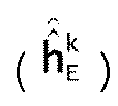 - à régler le signal de suppression d'écho en se basant sur la seconde estimation.
Priority Applications (2)
| Application Number | Priority Date | Filing Date | Title |
|---|---|---|---|
| EP16306298.7A EP3306825B1 (fr) | 2016-10-04 | 2016-10-04 | Procédure d'initialisation en deux étapes pour suppression d'écho analogique adaptatif |
| PCT/EP2017/074940 WO2018065346A1 (fr) | 2016-10-04 | 2017-10-02 | Procédure d'initialisation en deux étapes pour élimination d'écho analogique adaptative |
Applications Claiming Priority (1)
| Application Number | Priority Date | Filing Date | Title |
|---|---|---|---|
| EP16306298.7A EP3306825B1 (fr) | 2016-10-04 | 2016-10-04 | Procédure d'initialisation en deux étapes pour suppression d'écho analogique adaptatif |
Publications (2)
| Publication Number | Publication Date |
|---|---|
| EP3306825A1 EP3306825A1 (fr) | 2018-04-11 |
| EP3306825B1 true EP3306825B1 (fr) | 2019-03-06 |
Family
ID=57138015
Family Applications (1)
| Application Number | Title | Priority Date | Filing Date |
|---|---|---|---|
| EP16306298.7A Active EP3306825B1 (fr) | 2016-10-04 | 2016-10-04 | Procédure d'initialisation en deux étapes pour suppression d'écho analogique adaptatif |
Country Status (2)
| Country | Link |
|---|---|
| EP (1) | EP3306825B1 (fr) |
| WO (1) | WO2018065346A1 (fr) |
Families Citing this family (2)
| Publication number | Priority date | Publication date | Assignee | Title |
|---|---|---|---|---|
| US11393487B2 (en) * | 2019-03-28 | 2022-07-19 | Samsung Electronics Co., Ltd. | System and method for acoustic echo cancelation using deep multitask recurrent neural networks |
| TWI763552B (zh) * | 2021-07-05 | 2022-05-01 | 瑞昱半導體股份有限公司 | 傳送端阻抗匹配電路 |
Family Cites Families (4)
| Publication number | Priority date | Publication date | Assignee | Title |
|---|---|---|---|---|
| IT1184949B (it) * | 1985-05-14 | 1987-10-28 | Sip | Perfezionamento ai sistemi per la trasmissione numerica bidirezionale con cancellazione d eco |
| US7215765B2 (en) * | 2002-06-24 | 2007-05-08 | Freescale Semiconductor, Inc. | Method and apparatus for pure delay estimation in a communication system |
| US7009945B1 (en) * | 2003-06-18 | 2006-03-07 | Centillium Communications, Inc. | Dual-mode analog/digital adaptive echo cancellation in communication systems with asymmetric spectrum |
| EP3146646A4 (fr) * | 2014-05-23 | 2018-04-25 | Intel Corporation | Technique aveugle pour sélection de poids dans une structure d'émission et de réception simultanées |
-
2016
- 2016-10-04 EP EP16306298.7A patent/EP3306825B1/fr active Active
-
2017
- 2017-10-02 WO PCT/EP2017/074940 patent/WO2018065346A1/fr not_active Ceased
Non-Patent Citations (1)
| Title |
|---|
| None * |
Also Published As
| Publication number | Publication date |
|---|---|
| EP3306825A1 (fr) | 2018-04-11 |
| WO2018065346A1 (fr) | 2018-04-12 |
Similar Documents
| Publication | Publication Date | Title |
|---|---|---|
| US9673860B2 (en) | Method and apparatus for fast and accurate acquisition of crosstalk coefficients | |
| US11424785B2 (en) | Targeted rectangular conditioning | |
| US8270524B2 (en) | Method and apparatus for interference post-compensation using a bandwidth-adaptive postcoder interface | |
| US9020017B2 (en) | Signal processing method, device and system | |
| US9887736B2 (en) | Non-linear precoder with separate tracking | |
| EP2283639B1 (fr) | Ajustement de niveau de bruit d'émetteur dynamique pour systèmes de ligne d'abonné numérique | |
| MX2011006107A (es) | Metodo para entrenamiento robusto de precodificador de diafonia en canales con ruido por impulso. | |
| US9917617B2 (en) | Randomization of crosstalk probing signals | |
| EP2573946A1 (fr) | Évitement d'adaptation électrique durant les mesures de diaphonie | |
| US11632145B2 (en) | Method and apparatus for full-duplex communication over wired transmission media | |
| EP3306825B1 (fr) | Procédure d'initialisation en deux étapes pour suppression d'écho analogique adaptatif | |
| JP2019524024A (ja) | 帯域外トーンのクロストーク軽減 | |
| KR20120012460A (ko) | Dmt 모뎀들에서 다이나믹 레인지를 최적화하는 방법 및 장치 | |
| EP2955857B1 (fr) | Estimation des indicateurs de performance de vectorisation en service | |
| EP3168997B1 (fr) | Procédé et appareil pour vectoriser un multi-opérateur | |
| EP2779475B1 (fr) | Rétroaction d'erreur avec point de constellation détectée | |
| EP2736210A1 (fr) | Adaptation de la longeur d'extension cyclique pour des lignes vectorisée | |
| EP3076560A1 (fr) | Vectorisation sur des lignes d'abonnés numériques |
Legal Events
| Date | Code | Title | Description |
|---|---|---|---|
| PUAI | Public reference made under article 153(3) epc to a published international application that has entered the european phase |
Free format text: ORIGINAL CODE: 0009012 |
|
| STAA | Information on the status of an ep patent application or granted ep patent |
Free format text: STATUS: THE APPLICATION HAS BEEN PUBLISHED |
|
| AK | Designated contracting states |
Kind code of ref document: A1 Designated state(s): AL AT BE BG CH CY CZ DE DK EE ES FI FR GB GR HR HU IE IS IT LI LT LU LV MC MK MT NL NO PL PT RO RS SE SI SK SM TR |
|
| AX | Request for extension of the european patent |
Extension state: BA ME |
|
| RAP1 | Party data changed (applicant data changed or rights of an application transferred) |
Owner name: ALCATEL LUCENT |
|
| STAA | Information on the status of an ep patent application or granted ep patent |
Free format text: STATUS: REQUEST FOR EXAMINATION WAS MADE |
|
| 17P | Request for examination filed |
Effective date: 20181011 |
|
| RBV | Designated contracting states (corrected) |
Designated state(s): AL AT BE BG CH CY CZ DE DK EE ES FI FR GB GR HR HU IE IS IT LI LT LU LV MC MK MT NL NO PL PT RO RS SE SI SK SM TR |
|
| GRAP | Despatch of communication of intention to grant a patent |
Free format text: ORIGINAL CODE: EPIDOSNIGR1 |
|
| STAA | Information on the status of an ep patent application or granted ep patent |
Free format text: STATUS: GRANT OF PATENT IS INTENDED |
|
| INTG | Intention to grant announced |
Effective date: 20181126 |
|
| GRAS | Grant fee paid |
Free format text: ORIGINAL CODE: EPIDOSNIGR3 |
|
| GRAA | (expected) grant |
Free format text: ORIGINAL CODE: 0009210 |
|
| STAA | Information on the status of an ep patent application or granted ep patent |
Free format text: STATUS: THE PATENT HAS BEEN GRANTED |
|
| AK | Designated contracting states |
Kind code of ref document: B1 Designated state(s): AL AT BE BG CH CY CZ DE DK EE ES FI FR GB GR HR HU IE IS IT LI LT LU LV MC MK MT NL NO PL PT RO RS SE SI SK SM TR |
|
| REG | Reference to a national code |
Ref country code: GB Ref legal event code: FG4D |
|
| REG | Reference to a national code |
Ref country code: CH Ref legal event code: EP Ref country code: AT Ref legal event code: REF Ref document number: 1105953 Country of ref document: AT Kind code of ref document: T Effective date: 20190315 |
|
| REG | Reference to a national code |
Ref country code: DE Ref legal event code: R096 Ref document number: 602016010683 Country of ref document: DE |
|
| REG | Reference to a national code |
Ref country code: IE Ref legal event code: FG4D |
|
| REG | Reference to a national code |
Ref country code: NL Ref legal event code: MP Effective date: 20190306 |
|
| REG | Reference to a national code |
Ref country code: LT Ref legal event code: MG4D |
|
| PG25 | Lapsed in a contracting state [announced via postgrant information from national office to epo] |
Ref country code: NO Free format text: LAPSE BECAUSE OF FAILURE TO SUBMIT A TRANSLATION OF THE DESCRIPTION OR TO PAY THE FEE WITHIN THE PRESCRIBED TIME-LIMIT Effective date: 20190606 Ref country code: LT Free format text: LAPSE BECAUSE OF FAILURE TO SUBMIT A TRANSLATION OF THE DESCRIPTION OR TO PAY THE FEE WITHIN THE PRESCRIBED TIME-LIMIT Effective date: 20190306 Ref country code: FI Free format text: LAPSE BECAUSE OF FAILURE TO SUBMIT A TRANSLATION OF THE DESCRIPTION OR TO PAY THE FEE WITHIN THE PRESCRIBED TIME-LIMIT Effective date: 20190306 Ref country code: SE Free format text: LAPSE BECAUSE OF FAILURE TO SUBMIT A TRANSLATION OF THE DESCRIPTION OR TO PAY THE FEE WITHIN THE PRESCRIBED TIME-LIMIT Effective date: 20190306 |
|
| PG25 | Lapsed in a contracting state [announced via postgrant information from national office to epo] |
Ref country code: BG Free format text: LAPSE BECAUSE OF FAILURE TO SUBMIT A TRANSLATION OF THE DESCRIPTION OR TO PAY THE FEE WITHIN THE PRESCRIBED TIME-LIMIT Effective date: 20190606 Ref country code: HR Free format text: LAPSE BECAUSE OF FAILURE TO SUBMIT A TRANSLATION OF THE DESCRIPTION OR TO PAY THE FEE WITHIN THE PRESCRIBED TIME-LIMIT Effective date: 20190306 Ref country code: GR Free format text: LAPSE BECAUSE OF FAILURE TO SUBMIT A TRANSLATION OF THE DESCRIPTION OR TO PAY THE FEE WITHIN THE PRESCRIBED TIME-LIMIT Effective date: 20190607 Ref country code: LV Free format text: LAPSE BECAUSE OF FAILURE TO SUBMIT A TRANSLATION OF THE DESCRIPTION OR TO PAY THE FEE WITHIN THE PRESCRIBED TIME-LIMIT Effective date: 20190306 Ref country code: NL Free format text: LAPSE BECAUSE OF FAILURE TO SUBMIT A TRANSLATION OF THE DESCRIPTION OR TO PAY THE FEE WITHIN THE PRESCRIBED TIME-LIMIT Effective date: 20190306 Ref country code: RS Free format text: LAPSE BECAUSE OF FAILURE TO SUBMIT A TRANSLATION OF THE DESCRIPTION OR TO PAY THE FEE WITHIN THE PRESCRIBED TIME-LIMIT Effective date: 20190306 |
|
| REG | Reference to a national code |
Ref country code: AT Ref legal event code: MK05 Ref document number: 1105953 Country of ref document: AT Kind code of ref document: T Effective date: 20190306 |
|
| PG25 | Lapsed in a contracting state [announced via postgrant information from national office to epo] |
Ref country code: CZ Free format text: LAPSE BECAUSE OF FAILURE TO SUBMIT A TRANSLATION OF THE DESCRIPTION OR TO PAY THE FEE WITHIN THE PRESCRIBED TIME-LIMIT Effective date: 20190306 Ref country code: RO Free format text: LAPSE BECAUSE OF FAILURE TO SUBMIT A TRANSLATION OF THE DESCRIPTION OR TO PAY THE FEE WITHIN THE PRESCRIBED TIME-LIMIT Effective date: 20190306 Ref country code: IT Free format text: LAPSE BECAUSE OF FAILURE TO SUBMIT A TRANSLATION OF THE DESCRIPTION OR TO PAY THE FEE WITHIN THE PRESCRIBED TIME-LIMIT Effective date: 20190306 Ref country code: SK Free format text: LAPSE BECAUSE OF FAILURE TO SUBMIT A TRANSLATION OF THE DESCRIPTION OR TO PAY THE FEE WITHIN THE PRESCRIBED TIME-LIMIT Effective date: 20190306 Ref country code: ES Free format text: LAPSE BECAUSE OF FAILURE TO SUBMIT A TRANSLATION OF THE DESCRIPTION OR TO PAY THE FEE WITHIN THE PRESCRIBED TIME-LIMIT Effective date: 20190306 Ref country code: EE Free format text: LAPSE BECAUSE OF FAILURE TO SUBMIT A TRANSLATION OF THE DESCRIPTION OR TO PAY THE FEE WITHIN THE PRESCRIBED TIME-LIMIT Effective date: 20190306 Ref country code: AL Free format text: LAPSE BECAUSE OF FAILURE TO SUBMIT A TRANSLATION OF THE DESCRIPTION OR TO PAY THE FEE WITHIN THE PRESCRIBED TIME-LIMIT Effective date: 20190306 Ref country code: PT Free format text: LAPSE BECAUSE OF FAILURE TO SUBMIT A TRANSLATION OF THE DESCRIPTION OR TO PAY THE FEE WITHIN THE PRESCRIBED TIME-LIMIT Effective date: 20190706 |
|
| PG25 | Lapsed in a contracting state [announced via postgrant information from national office to epo] |
Ref country code: PL Free format text: LAPSE BECAUSE OF FAILURE TO SUBMIT A TRANSLATION OF THE DESCRIPTION OR TO PAY THE FEE WITHIN THE PRESCRIBED TIME-LIMIT Effective date: 20190306 Ref country code: SM Free format text: LAPSE BECAUSE OF FAILURE TO SUBMIT A TRANSLATION OF THE DESCRIPTION OR TO PAY THE FEE WITHIN THE PRESCRIBED TIME-LIMIT Effective date: 20190306 |
|
| REG | Reference to a national code |
Ref country code: DE Ref legal event code: R097 Ref document number: 602016010683 Country of ref document: DE |
|
| PG25 | Lapsed in a contracting state [announced via postgrant information from national office to epo] |
Ref country code: AT Free format text: LAPSE BECAUSE OF FAILURE TO SUBMIT A TRANSLATION OF THE DESCRIPTION OR TO PAY THE FEE WITHIN THE PRESCRIBED TIME-LIMIT Effective date: 20190306 Ref country code: IS Free format text: LAPSE BECAUSE OF FAILURE TO SUBMIT A TRANSLATION OF THE DESCRIPTION OR TO PAY THE FEE WITHIN THE PRESCRIBED TIME-LIMIT Effective date: 20190706 |
|
| PLBE | No opposition filed within time limit |
Free format text: ORIGINAL CODE: 0009261 |
|
| STAA | Information on the status of an ep patent application or granted ep patent |
Free format text: STATUS: NO OPPOSITION FILED WITHIN TIME LIMIT |
|
| PG25 | Lapsed in a contracting state [announced via postgrant information from national office to epo] |
Ref country code: DK Free format text: LAPSE BECAUSE OF FAILURE TO SUBMIT A TRANSLATION OF THE DESCRIPTION OR TO PAY THE FEE WITHIN THE PRESCRIBED TIME-LIMIT Effective date: 20190306 |
|
| 26N | No opposition filed |
Effective date: 20191209 |
|
| PG25 | Lapsed in a contracting state [announced via postgrant information from national office to epo] |
Ref country code: SI Free format text: LAPSE BECAUSE OF FAILURE TO SUBMIT A TRANSLATION OF THE DESCRIPTION OR TO PAY THE FEE WITHIN THE PRESCRIBED TIME-LIMIT Effective date: 20190306 |
|
| PG25 | Lapsed in a contracting state [announced via postgrant information from national office to epo] |
Ref country code: TR Free format text: LAPSE BECAUSE OF FAILURE TO SUBMIT A TRANSLATION OF THE DESCRIPTION OR TO PAY THE FEE WITHIN THE PRESCRIBED TIME-LIMIT Effective date: 20190306 |
|
| PG25 | Lapsed in a contracting state [announced via postgrant information from national office to epo] |
Ref country code: MC Free format text: LAPSE BECAUSE OF FAILURE TO SUBMIT A TRANSLATION OF THE DESCRIPTION OR TO PAY THE FEE WITHIN THE PRESCRIBED TIME-LIMIT Effective date: 20190306 |
|
| REG | Reference to a national code |
Ref country code: CH Ref legal event code: PL |
|
| PG25 | Lapsed in a contracting state [announced via postgrant information from national office to epo] |
Ref country code: LI Free format text: LAPSE BECAUSE OF NON-PAYMENT OF DUE FEES Effective date: 20191031 Ref country code: LU Free format text: LAPSE BECAUSE OF NON-PAYMENT OF DUE FEES Effective date: 20191004 Ref country code: CH Free format text: LAPSE BECAUSE OF NON-PAYMENT OF DUE FEES Effective date: 20191031 |
|
| REG | Reference to a national code |
Ref country code: BE Ref legal event code: MM Effective date: 20191031 |
|
| PG25 | Lapsed in a contracting state [announced via postgrant information from national office to epo] |
Ref country code: BE Free format text: LAPSE BECAUSE OF NON-PAYMENT OF DUE FEES Effective date: 20191031 |
|
| PG25 | Lapsed in a contracting state [announced via postgrant information from national office to epo] |
Ref country code: IE Free format text: LAPSE BECAUSE OF NON-PAYMENT OF DUE FEES Effective date: 20191004 |
|
| PG25 | Lapsed in a contracting state [announced via postgrant information from national office to epo] |
Ref country code: CY Free format text: LAPSE BECAUSE OF FAILURE TO SUBMIT A TRANSLATION OF THE DESCRIPTION OR TO PAY THE FEE WITHIN THE PRESCRIBED TIME-LIMIT Effective date: 20190306 |
|
| PG25 | Lapsed in a contracting state [announced via postgrant information from national office to epo] |
Ref country code: HU Free format text: LAPSE BECAUSE OF FAILURE TO SUBMIT A TRANSLATION OF THE DESCRIPTION OR TO PAY THE FEE WITHIN THE PRESCRIBED TIME-LIMIT; INVALID AB INITIO Effective date: 20161004 Ref country code: MT Free format text: LAPSE BECAUSE OF FAILURE TO SUBMIT A TRANSLATION OF THE DESCRIPTION OR TO PAY THE FEE WITHIN THE PRESCRIBED TIME-LIMIT Effective date: 20190306 |
|
| REG | Reference to a national code |
Ref country code: DE Ref legal event code: R081 Ref document number: 602016010683 Country of ref document: DE Owner name: VECIMA NETWORKS INC., VICTORIA, CA Free format text: FORMER OWNER: ALCATEL LUCENT, NOZAY, FR |
|
| REG | Reference to a national code |
Ref country code: GB Ref legal event code: 732E Free format text: REGISTERED BETWEEN 20220106 AND 20220112 |
|
| PG25 | Lapsed in a contracting state [announced via postgrant information from national office to epo] |
Ref country code: MK Free format text: LAPSE BECAUSE OF FAILURE TO SUBMIT A TRANSLATION OF THE DESCRIPTION OR TO PAY THE FEE WITHIN THE PRESCRIBED TIME-LIMIT Effective date: 20190306 |
|
| PGFP | Annual fee paid to national office [announced via postgrant information from national office to epo] |
Ref country code: DE Payment date: 20250430 Year of fee payment: 9 |
|
| PGFP | Annual fee paid to national office [announced via postgrant information from national office to epo] |
Ref country code: GB Payment date: 20251020 Year of fee payment: 10 |
|
| PGFP | Annual fee paid to national office [announced via postgrant information from national office to epo] |
Ref country code: FR Payment date: 20251020 Year of fee payment: 10 |