EP3307012B1 - Verfahren und vorrichtung für kommunikationen - Google Patents
Verfahren und vorrichtung für kommunikationen Download PDFInfo
- Publication number
- EP3307012B1 EP3307012B1 EP16799108.2A EP16799108A EP3307012B1 EP 3307012 B1 EP3307012 B1 EP 3307012B1 EP 16799108 A EP16799108 A EP 16799108A EP 3307012 B1 EP3307012 B1 EP 3307012B1
- Authority
- EP
- European Patent Office
- Prior art keywords
- dsc
- identifier
- cluster
- information
- network
- Prior art date
- Legal status (The legal status is an assumption and is not a legal conclusion. Google has not performed a legal analysis and makes no representation as to the accuracy of the status listed.)
- Active
Links
Images





Classifications
-
- H—ELECTRICITY
- H04—ELECTRIC COMMUNICATION TECHNIQUE
- H04W—WIRELESS COMMUNICATION NETWORKS
- H04W4/00—Services specially adapted for wireless communication networks; Facilities therefor
- H04W4/70—Services for machine-to-machine communication [M2M] or machine type communication [MTC]
-
- H—ELECTRICITY
- H04—ELECTRIC COMMUNICATION TECHNIQUE
- H04L—TRANSMISSION OF DIGITAL INFORMATION, e.g. TELEGRAPHIC COMMUNICATION
- H04L63/00—Network architectures or network communication protocols for network security
- H04L63/20—Network architectures or network communication protocols for network security for managing network security; network security policies in general
-
- H—ELECTRICITY
- H04—ELECTRIC COMMUNICATION TECHNIQUE
- H04W—WIRELESS COMMUNICATION NETWORKS
- H04W12/00—Security arrangements; Authentication; Protecting privacy or anonymity
- H04W12/06—Authentication
-
- H—ELECTRICITY
- H04—ELECTRIC COMMUNICATION TECHNIQUE
- H04W—WIRELESS COMMUNICATION NETWORKS
- H04W4/00—Services specially adapted for wireless communication networks; Facilities therefor
- H04W4/06—Selective distribution of broadcast services, e.g. multimedia broadcast multicast service [MBMS]; Services to user groups; One-way selective calling services
-
- H—ELECTRICITY
- H04—ELECTRIC COMMUNICATION TECHNIQUE
- H04W—WIRELESS COMMUNICATION NETWORKS
- H04W76/00—Connection management
- H04W76/10—Connection setup
-
- H—ELECTRICITY
- H04—ELECTRIC COMMUNICATION TECHNIQUE
- H04L—TRANSMISSION OF DIGITAL INFORMATION, e.g. TELEGRAPHIC COMMUNICATION
- H04L41/00—Arrangements for maintenance, administration or management of data switching networks, e.g. of packet switching networks
- H04L41/50—Network service management, e.g. ensuring proper service fulfilment according to agreements
-
- H—ELECTRICITY
- H04—ELECTRIC COMMUNICATION TECHNIQUE
- H04W—WIRELESS COMMUNICATION NETWORKS
- H04W4/00—Services specially adapted for wireless communication networks; Facilities therefor
- H04W4/06—Selective distribution of broadcast services, e.g. multimedia broadcast multicast service [MBMS]; Services to user groups; One-way selective calling services
- H04W4/08—User group management
-
- H—ELECTRICITY
- H04—ELECTRIC COMMUNICATION TECHNIQUE
- H04W—WIRELESS COMMUNICATION NETWORKS
- H04W84/00—Network topologies
- H04W84/18—Self-organising networks, e.g. ad-hoc networks or sensor networks
-
- H—ELECTRICITY
- H04—ELECTRIC COMMUNICATION TECHNIQUE
- H04W—WIRELESS COMMUNICATION NETWORKS
- H04W84/00—Network topologies
- H04W84/18—Self-organising networks, e.g. ad-hoc networks or sensor networks
- H04W84/20—Leader-follower arrangements
-
- H—ELECTRICITY
- H04—ELECTRIC COMMUNICATION TECHNIQUE
- H04W—WIRELESS COMMUNICATION NETWORKS
- H04W92/00—Interfaces specially adapted for wireless communication networks
- H04W92/04—Interfaces between hierarchically different network devices
-
- H—ELECTRICITY
- H04—ELECTRIC COMMUNICATION TECHNIQUE
- H04W—WIRELESS COMMUNICATION NETWORKS
- H04W92/00—Interfaces specially adapted for wireless communication networks
- H04W92/16—Interfaces between hierarchically similar devices
- H04W92/18—Interfaces between hierarchically similar devices between terminal devices
Definitions
- the present invention relates to the field of communications, and particularly to a communication method and device concerning machine-type equipment.
- Fig.1 is a schematic architectural diagram of an existing cellular network, and as illustrated, in the existing cellular system, a terminal determines a serving base station according to the strength of a downlink pilot signal, and the serving base station is responsible for providing the accessing terminal with a data transmission service.
- the serving base station forwards uplink data received from the terminal to a core network.
- the core network is responsible for verifying the identity of the terminal, storing context information of the terminal, and providing the accessing terminal with a connectivity service to an external network.
- the terminal is registered with the network in an Attach procedure. While the terminal is being registered with the network, a Mobility Management Entity (MME) of the core network is responsible for storing state information of the terminal, including security context information, activated session information, positional area information, etc.
- MME Mobility Management Entity
- the state information of the terminal is stored in the core network, so if the accessing terminal is a machine-type terminal, then there may be two problems as follows.
- the number of machine-type terminals is expected to go far beyond the number of existing terminals (up to the level of possibly 50 to 100 billions as anticipated), so if a complete context is created in the core network for each machine-type terminal, then there may be an unacceptable storage burden for the core network; and secondly the core network is also involved in a connectivity management function of the existing terminal, and this means that a lot of signaling in the core network may be produced each time when the terminal becomes connected, so if a large number of machine-type terminals access the network, there may be easily a storm of signaling.
- WO2014/203205 A1 relates to a multi-tier network topology where some of the MTC devices will play a second role as data aggregators, consolidating data from several other nearby devices and hence reducing the impact on the mobile network.
- Different radio access technologies like Wi Fi or LTE, can be used to aggregate data.
- different Radio Access Networks can be used to connect the MTC aggregators to the MTC Application Server.
- the LTE Mobile Network is used as the backhaul and LTE is also used for aggregator RAT; (2) The LTE Mobile Network is used as the backhaul and Wi Fi is used for aggregator RAT; (3) Mobile Relay based aggregation; and (4) Multi-tier hierarchical aggregators. Limiting overhead impact on the LTE uplink is taught by the disclosure.
- WO2011/123755 A1 relates to systems, methods, and instrumentalities to optimize procedures relating to machine type communication devices.
- Individual UEs may be grouped together in order to optimize procedures relating to members of the group.
- a group of UE devices may be predefined or a group may be configured by a network associated with the UEs.
- One or more of the members of the group may be designated as a special UE or a master UE.
- the special UE or master UE may perform an action on behalf of one or more members of the group.
- WO2011/087826 A1 relates to methods and apparatus are provided for performing group-based machine-to-machine communication.
- Machine-type communication (MTC) wireless transmit/receive units (WTRUs) may operate in MTC groups.
- MTC WTRUs belonging to the same MTC group may use a group-based International Mobile Subscriber Identity (IMSI) and a group-based IP address for data transmission.
- IMSI International Mobile Subscriber Identity
- Group-based network registration may be performed.
- a group-based IP address and radio resources may be proactively allocated for an MTC group.
- a master MTC may perform network registration/attachment process on behalf of the MTC group.
- a group of MTC WTRUs may transmit data according to staggered time windows.
- WO2009/104171 A2 relates to a method for self-organizing a plurality of nodes of a communication network into at least one cluster of nodes, the plurality of nodes comprising at least one potential cluster head, and being able to communicate within the communication network over a plurality of broadcast communication channels, said method comprising for said at least one potential cluster head the act of broadcasting an advertisement message over a first communication channel, said advertisement message comprising a first information related to the capacities of the potential cluster head with regards to a given application, and second information related to a second communication channel over which the plurality of nodes can exchange messages with said potential cluster head, and the act of receiving over the second communication channel a response message if any from a node, said response message comprising an indication that the node, based on the first information, has selected the potential cluster head as the head to a cluster comprising at least said potential cluster head and said node.
- Embodiments of the invention provide a communication method and device so as to reduce a burden of storage and signaling handling on a core network due to an accessing device.
- An embodiment of the invention provides a communication method including the steps of claim 1 and performed by an authorized device.
- the authorized device is configured with the DSC and subscribes in advance with an operator for authorization of the DSC; the authorized device and the endpoints constitute a dynamic network in an ad hoc manner, and the DSC is responsible for managing the network; the DSC establishes a Me1 interface connection with the NSC of the core network; the DSC transmits system broadcast information via an air interface to the endpoints; the DSC discovers an adjacent DSC via the air interface and establishes a Me2 interface connection with the adjacent DSC; wherein the endpoints are Machine-Type Communication, MTC-like accessing terminals.
- An embodiment of the invention provides a communication method including: receiving by a core network a communication request message transmitted by a Distributed Service Center, DSC configured as a function for transmitting information with a core network over a backhaul network, onto the authorized device; and responding by a core network to the communication request message;
- DSC Distributed Service Center
- An embodiment of the invention provides a communication device including: an information determining module configured to determine functional parameter configuration information of a Distributed Service Center, DSC configured as a function for transmitting information with a core network over a backhaul network, onto the authorized device, wherein the functional parameter configuration information is sent by a core network, and comprises one or a combination of: a DSC device identifier, a network identifier, a cluster identifier, cluster information, a service identifier, a Network Service Center, NSC identifier of the core network and NSC address information of the core network, wherein the NSC is configured as a function for terminating a control-plane interface of a access network to a core network, onto the core network; the cluster is constituted by DSC and surrounding endpoints connected with the DSC; a demand determining module configured to determine a communication demand on the DSC according to the functional parameter configuration information; and an executing module configured to transmit a communication request message to a corresponding device, wherein the corresponding device comprises the NSC
- the dynamic distributed network architecture can be put into operation to reduce a burden of storage and signaling handling on the core network due to an accessing device; and also the control function can be localized to thereby greatly shorten a delay in the control-plane signaling procedure.
- an MTC-like terminal is managed over a "distributed dynamic network" in the technical solutions according to the embodiments of the invention.
- a cluster head and a series of endpoints constitute a cluster, where the endpoints in the cluster are controlled by the cluster device to communicate with each other.
- the endpoints communicate with each other in the cluster in the unlicensed frequency band of 2.4GHz in a frequency hop mode in which interference to each other can be avoided.
- Respective clusters are independent of each other, and endpoint members in the different clusters cannot communicate with each other.
- Fig.2 is a schematic structural diagram of a wireless communication system, and as illustrated, the wireless communication system includes an MESH access network, a backhaul network, and a core network, where the MESH access network is connected with the core network through the backhaul network.
- a MESH network supports multiple hops via an air interface, direct communication between devices via an air interface, and other characteristics
- the MESH access network in embodiments of the invention further supports the self-organized and infrastructureless characteristics in addition to the characteristics of the traditional MESH network.
- the backhaul network includes a wired backhaul network, a wireless backhaul network, and a mobile cellular backhaul network.
- the core network includes various special and general servers, data center, router and the like and is in charge of signing management, user identification, authentication, strategy control, accounting management, business management and the like for various accessing devices.
- the MESH access network primarily provides services to a Machine-Type Communication (MTC) access device, where a sensor (e.g., a temperature sensor, a pressure sensor, a camera, etc.) can be bound with an endpoint, or an actuator (e.g., an accelerator, a brake, a steering device, a mechanical arm, etc.) can be bound with an endpoint, or a physical entity (e.g., a vehicle, a bicycle, a helmet, glasses, a smart watch, an unmanned aircraft, etc.) can be bound with an endpoint.
- MTC Machine-Type Communication
- a Me1 interface is an interface established between a DSC and an NSC.
- AMe2 interface is an interface established between a DSC and another DSC.
- a Me3 interface is an interface established between a DSC and an EP (End Point).
- a Me4 interface is an interface established between an EP and another EP.
- a Dc1 interface is an interface established between a DSC and a core network DSC management functional device.
- the MESH access network includes at least one DSC and at least one EP, and the core network includes at least one NSC.
- the EP is an MTC accessing device or a wearable device capable of communication, which is provided with a data transmission service by accessing a "cluster".
- the EP can be bound with a specific physical device, e.g., various sensors, various actuators, an accelerator, a brake, a mechanical arm, an aircraft, a vehicle, a bicycle, a safety helmet, smart glasses, a smart watch, etc.
- the EP with different communication functions can be selected for a different specific physical device to be bound.
- the EP typically operates in a communication scenario with a short distance (e.g., shorter than 100m), and a low data rate (e.g., lower than 1000 bits/s).
- the embodiments of the invention can also be applicable to an EP operating over a long distance and at a high data rate.
- DSC Distributed Service Center
- the DSC is configured to transmit information about an EP in a corresponding cluster with the core network over the backhaul network, where the DSC is connected with each EP in the corresponding cluster.
- the DSC can be configured as a function onto various devices including a mobile end device, a base station device, a server device, or other hardware devices.
- the DSC and the surrounding endpoints connected with the DSC constitute a cluster.
- the DSC is responsible for managing and maintaining the cluster.
- the DSC manages the EPs in the corresponding cluster, coordinates communication with another adjacent cluster, and manages interference.
- the DSC may further coordinate interference with a radio resource control entity in a heterogeneous system which is adjacent or in the same coverage area and communication with the heterogeneous system across the systems. For example, the DSC can notify a surrounding DSC or LSC of time or frequency information of a radio resource allocated for "intra-cluster communication".
- the surrounding DSC or LSC is avoided from communicating at the same time or frequency.
- the DSC can further notify the surrounding DSC or LSC of interference information measured by the DSC, or one or more EPs in the cluster; and correspondingly if the surrounding DSC or LSC determine interference thereof to communication in another cluster or a "local access network", then it may lower the interference by lowering transmit power thereof or otherwise.
- the DSC In order to manage a service layer and the cluster members, the DSC is responsible for participating in maintaining a list of members, verifying the identities of the cluster members, and participating in maintaining device types and service demands associated with the endpoints.
- the DSC operates as a control point of the cluster, and is also responsible for coordinating communication with another adjacent cluster, and managing interference therewith.
- the DSC may be further responsible for coordinating interference with a radio resource control entity in a heterogeneous system which is adjacent or in the same coverage area, and communication with the heterogeneous system across the systems (for example, the DSC is responsible for coordinating a base station to coordinate interference).
- the DSC primarily constitutes a cluster together with the surrounding endpoint-type terminals, and the DSC is responsible for managing the "cluster".
- the DSC supports software and hardware decoupling, and software configurable functions.
- the DSC is responsible for controlling an access of an EP-type terminal, and the DSC needs to verify the identity of the accessing terminal. Since a cluster-based management strategy is applied to the core network, the DSC is responsible for report information about the cluster managed by the DSC to the core network, where the information about the cluster includes information about the number of members in the cluster managed by the DSC, and information about a service activated in the cluster managed by the DSC.
- the NSC is responsible for terminating a control-plane interface of the access network to the core network, and the NSC supports the software and hardware decoupling and software configurable functions, and participates in managing MTC-like terminals (EPs).
- the Network Service Center (NSC) supports the software and hardware decoupling and software configurable functions.
- a plurality of DSCs in the distributed dynamic network can establish a Me1 interface with the NSC as follows.
- the NSC is configured to transmit information about the DSCs received through the backhaul network to the core network. Stated otherwise, the connectivity managing NSC is responsible for terminating a control-plane connection of the MESH access network to the core network.
- the NSC is responsible for verifying the identities of the DSCs, and establishing a secured tunnel.
- the NSC can verify identities of the DSCs, and establish a secured tunnel for transmitting data through the backhaul network between the DSCs after they pass the verification.
- the NSC verifies identities of the DSCs in a certificate mechanism, and establishes an IPsec secured channel to thereby guarantee the security of the Me1 interface.
- the NSC can manage the EPs and specific accessing devices connected with the DSCs at the service and identity layers.
- the NSC is responsible for handling control-plane signaling received from the MESH access network and the cellular access network by verifying the identities of the EPs and the devices, verifying and activating the device types and the service types associated with the EPs, activating sessions to a specific external network for the devices, etc.
- the NSC is responsible for managing the state information of the EPs, including tracking management (information about the "cluster" currently accessed by the EPs), session management (a service currently activated for an EP), and identity management (e.g., the device types and the service types to which the EPs subscribe).
- tracking management information about the "cluster" currently accessed by the EPs
- session management a service currently activated for an EP
- identity management e.g., the device types and the service types to which the EPs subscribe.
- the NSC is a centralized control unit, and the DSCs are distributed control units.
- the DSCs are responsible for controlling local functions for which a short delay is required, and the NSC is responsible for controlling a global function for which a short delay is not required, and high security is required.
- One or more NSCs can be deployed in the core network, and the different NSCs are peers of each other.
- the device performing this function is located in the core network, and responsible for authenticating an authorized device, controlling the authorized device to start a DSC operating mode, managing the authorized device in which the Distributed Service Center (DSC) function is enabled, configuring the authorized device with necessary configuration parameters for the authorized device to operate in the DSC mode, and collecting state information of the "cluster" from the DSC after the DSC is started.
- DSC Distributed Service Center
- the Authorized Device (AD) with the Distributed Service Center (DSC) function subscribes in advance with an operator for authorization of the DSC function, and after the AD is started, it firstly initiates a registration procedure with the core network; and the core network registering the AD verifies the identity of the AD, and authorizes the AD according to the subscription information to enable the DSC function.
- AD Distributed Service Center
- the authorized device configured with the DSC function, and the MTC-like accessing terminals (EPs) constitute a dynamic network in a self-organized manner
- the DSC is responsible for managing the network
- the AD configured with the DSC function manages an access of the MTC-like accessing terminals (EPs).
- the DSC establishes a control-plane interface, i.e., a Me1 interface (the Me1 interface is used for verifying the identities of the EPs with the assistance of the core network, and for the DSC to report the state information about the "cluster" to the core network) with the core network NSC, and the NSC verifies the identity of the DSC during establishing the interface.
- the DSC transmits the network information, the cluster information, the service information, etc., by broadcasting the information among the cluster members (EPs) via an air interface.
- the DSC After the DSC is started, the DSC discovers an adjacent "cluster" by detecting, or receiving a report from a cluster member, and establishes a Me2 interface with a DSC in the adjacent cluster to perform functions of coordinating radio resources, and avoiding interference.
- the AD is registered with the network and enables the DSC function; the DSC establishes a Me1 interface connection with the core network NSC; the DSC transmits system broadcast information via an air interface; the DSC discovers an adjacent DSC (adjacent cluster) directly via the air interface and establishes a Me2 interface connection; the DSC discovers an adjacent DSC (adjacent cluster) indirectly through a cluster member EP and establishes an Me2 interface; and the DSC notifies the DSC management functional device at the core network side of state information of the "cluster", so that the embodiment in which the DSC, the EP, and the core network NSC manage in cooperation an MTC-like terminal over a "distributed dynamic network" will also be described in connection with the embodiments of the DSC, the EP, and the core network NSC in the respective contexts
- the DSC, the EP, and the NSC at the core network side are described together, they may not necessarily cooperate with each other, but in fact, if they operate separately, then respective problems of the DSC, the EP, and the NSC at the core network side will also be addressed, although they can operate in cooperation for a better technical effect.
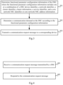
- Fig.3 is a schematic flow chart of a communication method performed on a DSC, and as illustrated, the method can include the following steps.
- the step 301 is to determine functional parameter configuration information of the DSC, where the functional parameter configuration information includes one or a combination of: a DSC device identifier, a network identifier, a cluster identifier, cluster information, a service identifier, and a core network NSC identifier or core network NSC address information.
- the step 302 is to determine a communication demand on the DSC according to the functional parameter configuration information.
- the step 303 is to transmit a communication request message to a corresponding device.
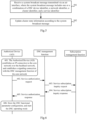
- Fig.4 is a schematic flow chart of a communication method performed on a core network, and as illustrated, the method can include the following steps.
- the step 401 is to receive a communication request message transmitted by a DSC.
- the step 402 is to respond to the communication request message.
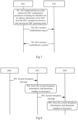
- Fig.5 is a schematic flow chart of a communication method performed on an EP, and as illustrated, the method can include the following steps.
- the step 501 is to receive a system broadcast message transmitted via an air interface, where the system broadcast message includes one or a combination of a DSC device identifier, a network identifier, a cluster identifier, and a service identifier.
- the step 502 is to update cluster state information according to the system broadcast message.
- the AD will be registered with the network, and enable the DSC function, as described in this embodiment, and in this flow, the DSC and the core network will operate respectively as follows.
- the AD After the AD is connected with the core network, the AD transmits a service authorization request message to a device managing the DSC on the core network, where the service authorization request message carries identification information and identity verification information of the DSC.
- the AD receives a service authorization response message transmitted by the device managing the DSC, where the service authorization response message carries the functional parameter configuration information.
- a communication request message transmitted by the DSC is the service authorization request message transmitted by the DSC connected with the core network, where the service authorization request message carries the identification information and the identity verification information of the DSC.
- a response is made to the communication request message as follows.
- the functional parameter configuration information of the DSC is determined according to the identification information and the identity verification information of the DSC, and subscription information, where the functional parameter configuration information includes one or a combination of: a DSC device identifier, a network identifier, a cluster identifier, cluster information, a service identifier, and a core network NSC identifier and core network NSC address information.
- a service authorization response message is transmitted to the DSC, where the service authorization response message carries the functional parameter configuration information.
- the AD establishes a signaling connection with the DSC control function of the core network through an IP connectivity service provided by the cellular network or the fixed backhaul network, and the DSC control function authorizes the AD according to the subscription condition of the AD to start the DSC operating mode.
- the AD has been represented as "AD (DSC)"
- the AD is authorized by the device controlling the DSC function in the core network to enable the DSC function, that is, the AD can operate with the DSC function to manage an MTC-like terminal over the "distributed dynamic network”.
- the AD may also be referred to as a DSC in the description.
- Fig.6 is a schematic flow chart of the AD being registered with the network, and enabling the DSC function, and as illustrated, the flow can be as follows.
- the AD establishes an IP connection to the core network through the backhaul network, and a signaling connection with the DSC management function of the core network.
- the AD transmits a service authorization request to the DSC management function, where the service authorization request carries a device ID of the authorized device, and identity verification information of the authorized device.
- the DSC management function transmits a service inquiry request to a subscription management function, where the service inquiry request carries the ID and the identity verification information of the authorized device, and a DSC indicator of a service type.
- the subscription management function makes an inquiry of whether the device has subscribed with the DSC function, according to pre-stored subscription information, and the device ID, and if there is still valid authorization for the DSC function with which the device has subscribed, then the subscription management function will transmit a service subscription inquiry response to the DSC management function, where the service subscription inquiry response carries the device identifier, and a DSC function enabling instruction.
- the DSC management function transmits a DSC functional parameter configuration and the DSC function enabling instruction to the authorized device in a service authorization response message, where the DSC functional parameter configuration includes a network identifier, a cluster identifier, a service identifier, and other information, and also an identifier of the core network NSC, or address information of the core network NSC, so that the DSC subsequently establishes a Me1 interface to the NSC.
- the AD stores the DSC functional parameter configuration, and starts the DSC operating mode.
- the DSC will determine according to the functional parameter configuration information that a communication demand on the DSC is to establish a communication connection via a Me1 interface, a communication request message transmitted to the NSC is a Me1 interface establishment request message.
- the DSC will store state information of successful Me1 interface establishment upon reception of a Me1 interface establishment complete message returned by the NSC.
- the communication request message transmitted by the DSC is the Me1 interface establishment request message.
- a response is made to the communication request message by returning the Me1 interface establishment complete message.
- the DSC before the DSC provides an EP device with access and data transmission services, the DSC firstly establishes a Me1 interface with the core network NSC (e.g., the core network NSC needs to participate via the Me1 interface in controlling attachment and service established of some type of EP).
- the DSC being started can obtain the identifier of the NSC, or the address information of the core network NSC from the DSC management function of the core network, where the information is used for the DSC to establish a control-plane interface between the DSC and the NSC.
- Fig.7 is a schematic flow chart of a DSC establishing a Me1 interface with a core network NSC, and as illustrated, the flow can be as follows.
- the AD obtains DSC configuration parameters including the identifier of the NSC, or the address information of the NSC from the DSC management function before starting the DSC operating mode.
- the DSC initiates a Me1 interface establishment request message to the NSC according to the address information of the target NSC, where the Me1 interface establishment request message carries the device identifier of the DSC, the network identifier, the cluster identifier, the service identifier, and the identity verification information of the DSC.
- the NSC verifies the identity of the DSC according to the identity verification information received from the DSC, and stores state information of successful Me1 interface establishment and transmits a Me1 interface establishment complete message to the DSC after finishing the identity verification, where the Me1 interface establishment complete message carries the device ID of the NSC, and the identity verification information of the NSC.
- the DSC verifies the identity of the NSC according to the identity verification information received from the NSC, and stores the Me1 interface establishment complete message after passing the identity verification.
- the DSC will transmit system broadcast information, which can carry network information, cluster information, and service information, via an air interface as described in this embodiment, and in this flow, the DSC and the EP will operate respectively as follows.
- the DSC will determine according to the functional parameter configuration information that a communication demand on the DSC is to broadcast in the cluster the system information to be known to the devices in the cluster.
- a communication request message transmitted to a corresponding device is a system broadcast message transmitted via an air interface, where the system broadcast message includes one or a combination of the identifier of the DSC, the network identifier, the cluster identifier, and the service identifier.
- system broadcast message can further include forward information indicating whether the system broadcast message needs to be forwarded by the receiving device.
- the EP receives the system broadcast message transmitted via the air interface, where the system broadcast message includes one or a combination of the identifier of the DSC, the network identifier, the cluster identifier, and the service identifier.
- the EP updates state information of the cluster according to the system broadcast message transmitted via the air interface.
- system broadcast message can further include the forward information indicating whether the system broadcast message needs to be forwarded by the receiving device.
- the EP forwards the system broadcast message to another EP via the air interface upon determining according to the forward information that the system broadcast message needs to be forwarded.
- the forward information can include the largest number N of hops, and an indicator M of the number of hops, where M and N are natural numbers;
- the EP will determine that the system broadcast message needs to be forwarded, and increase M by 1 while forwarding it; and if M is equal to N, then the EP will determine that the system broadcast message does not need to be forwarded.
- the system broadcast information is transmitted via the air interface so that on one hand, a new EP device (EP device newly accessing the network) selects the network and the "cluster", and on the other hand, the air interface broadcast information can assist adjacent DSCs (or adjacent clusters) in discovering each other. Furthermore since the DSC is responsible for maintaining a list of cluster members, information about the list of cluster members carried in the system broadcast information can be used for the EP to discover another EP member in the cluster.
- the coverage area of the cluster needs to be extended in a multi-hop manner, so multi-hop transmission can be supported using the air interface system broadcast information in the cluster controlled by the DSC, that is, those EP members in the cluster, which receiving the system broadcast message transmitted by the DSC can forward the system broadcast message, and the DSC can control the largest number of hops over which the system broadcast message is forwarded via the air interface, using the parameter "the largest number of hops".
- Fig.8 is a schematic flow chart of the DSC transmitting system broadcast information via an air interface, and as illustrated, the flow can be as follows.
- the DSC transmits a system broadcast message via an air interface, where the system broadcast message carries the device identifier of the DSC, the network identifier, the cluster identifier, the service identifier, information about the largest number of hops, the indicator of the number of hops which is set to 1, and the information about the list of cluster members including information about a list of currently accessing EPs in the cluster.
- an EP1 in the cluster updates its stored state information of the cluster upon reception of the system broadcast information transmitted by the currently serving DSC in the cluster via the air interface, and determines whether to forward the system broadcast information according to the largest number of hops and the indicator of the number of hops, and if the indicator of the number of hops does not exceed the largest number of hops, then the EP1 will forward the system broadcast information.
- the EP1 transmits system broadcast information via the air interface, where the system broadcast information carrying the device identifier of the EP, the device identifier of the DSC, the network identifier, the cluster identifier, the service identifier, the largest number of hops, the indicator of the number of hops (2), and the information about the list of cluster members; and the indicator of the number of hops is the original number of hops plus 1.
- a cluster member EP2 updates its stored state information of the cluster upon reception of the system broadcast information transmitted by the currently serving DSC in the cluster via the air interface, and determines whether to forward the system broadcast information, according to the largest number of hops, and the indicator of the number of hops, and if the indicator of the number of hops does not exceed the largest number of hops, then the EP1 will forward the system broadcast information.
- the DSC will discover an adjacent DSC (adjacent cluster) directly via an air interface, and establish a Me2 interface connection, as described in this embodiment, where as referred to in this embodiment, DSC1 refers to a DSC broadcasting a system broadcast message, and DSC2 refers to a DSC initiating a Me2 interface connection upon reception of the system broadcast message, so the DSC1 and the DSC2 operate respectively as follows in this flow.
- DSC1 refers to a DSC broadcasting a system broadcast message
- DSC2 refers to a DSC initiating a Me2 interface connection upon reception of the system broadcast message
- the DSC1 receives a Me2 interface establishment request message transmitted by the other DSC2, where the Me2 interface establishment request message carries one or a combination of the device identifier of the DSC1, the identifier of the network, the identifier of the cluster, and the identifier of a service provided by the DSC1.
- the DSC1 transmits a Me2 interface establishment complete message to the other DSC2.
- information carried in the Me2 interface establishment complete message is obtained from a system broadcast message transmitted by the DSC1.
- the DSC2 receives the system broadcast message transmitted by the other DSC1, where the system broadcast message includes one or a combination of the device identifier of the other DSC1, the network identifier of the other DSC1, the cluster identifier of the other DSC1, and the service identifier of the other DSC1.
- the DSC2 transmits the Me2 interface establishment request message to the other DSC1, where the Me2 interface establishment request message includes one or a combination of the device identifier of the other DSC1, the network identifier of the other DSC1, the cluster identifier of the other DSC1, and the service identifier of the other DSC1.
- the DSC2 receives the Me2 interface establishment complete message returned by the other DSC1.
- Fig.9 is a schematic flow chart of the DSC discovering an adjacent DSC (adjacent cluster) directly via an air interface, and establishing a Me2 interface connection, and as illustrated, the flow can be as follows.
- the DSC1 transmits a system broadcast message via an air interface, where the system broadcast message carries the device identifier of the DSC, the network identifier, the cluster identifier, the service identifier, information about the largest number of hops, the indicator of the number of hops which is set to 1, and information about the list of cluster members including information about the list of currently accessing EPs in the cluster.
- the DSC2 receiving the system message transmitted directly from the adjacent DSC1 stores information about the cluster managed by the DSC1, and initiates a Me2 interface establishment procedure for the DSC1.
- the DSC2 transmits a Me2 interface establishment message to the DSC1, where the Me2 interface establishment message carries the device identifier of the source SC, the identifier of the source network, the identifier of the source cluster, the identifier of the source service, and the identifier of the target DSC.
- the DSC1 admitting establishment of a Me2 interface with the DSC2 transmits a Me2 interface establishment complete message to the DSC2.
- the DSC will discover an adjacent DSC (adjacent cluster) indirectly through a cluster member EP, and establish a Me2 interface connection, as described in this embodiment, where as referred to in this embodiment, DSC1 refers to a DSC broadcasting a system broadcast message, DSC2 refers to a DSC initiating a Me2 interface connection upon reception of the system broadcast message, EP1 refers to an EP served by the DSC1, and EP2 refers to an EP served by the DSC2 where the EP1 forwards the system broadcast message to the EP2 according to forward information (including the indicator of the number of hops, and the largest number of hops in the example) upon reception of the system broadcast message, and the EP2 further forwards the system broadcast message to the DSC2 according to the forward information (including the indicator of the number of hops, and the largest number of hops in the example), so the DSC1, the EP1, the EP2, and the DSC2 operate respectively as follows.
- DSC1 refers to a DSC broadcasting a system broadcast message
- the DSC1 receives a Me2 interface establishment request message transmitted from the other DSC2, where the Me2 interface establishment request message carries one or combination of the device identifier of the DSC1, the identifier of the network, the identifier of the cluster, and the identifier of a service provided by the DSC1.
- the DSC1 returns a Me2 interface establishment complete message to the other DSC2.
- the EP1 receives a system broadcast message broadcasted by the DSC1, determines that the system broadcast message needs to be forwarded, according to the forward information, and forwards the system broadcast message.
- the EP2 receives the system broadcast message broadcasted by the EP1, determines that the system broadcast message needs to be forwarded, according to the forward information, and forwards the system broadcast message.
- the DSC2 receives the system broadcast message transmitted by the other DSC1, where the system broadcast message includes one or a combination of the device identifier of the other DSC1, the network identifier of the other DSC1, the cluster identifier of the other DSC1, and the service identifier of the other DSC1.
- the DSC2 transmits the Me2 interface establishment request message to the other DSC1, where the Me2 interface establishment request message carries includes one or a combination of the device identifier of the other DSC1, the network identifier of the other DSC1, the cluster identifier of the other DSC1, and the service identifier of the other DSC1.
- the DSC2 receives the Me2 interface establishment complete message returned by the other DSC1.
- the system broadcast message transmitted by the other DSC is forwarded by the EP.
- the system broadcast message transmitted by the other DSC1 is forwarded by the EP1 and the EP2 in this example.
- Fig.10 is a schematic flow chart of the DSC discovering an adjacent DSC (adjacent cluster) indirectly through a cluster member EP, and establishing a Me2 interface connection, and as illustrated, the flow can be as follows.
- the DSC1 transmits a system broadcast message via an air interface, where the system broadcast message carries the device identifier of the DSC, the network identifier, the cluster identifier, the service identifier, information about the largest number of hops, the indicator of the number of hops which is set to 1, and the information about the list of cluster members including information about a list of currently accessing EPs in the cluster.
- the member EP1 in the cluster of the DSC1 updates its stored state information of the cluster upon reception of the system broadcast information transmitted by the currently serving DSC in the cluster via the air interface, and determines whether to forward the system broadcast information, according to the largest number of hops and the indicator of the number of hops, and if the indicator of the number of hops does not exceed the largest number of hops, then the EP1 will forward the system broadcast information.
- the member EP2 in the cluster of the DSC2 decides to notify the DSC2 of an event of the adjacent cluster (DSC1) discovered by the EP2, upon reception of the system broadcast message transmitted by the EP1.
- DSC1 adjacent cluster
- the EP2 transmits an adjacent cluster discovery message to the DSC2, where the adjacent cluster discovery message carries the device identifier of the adjacent DSC, the identifier of the adjacent network, the identifier of the adjacent cluster, and the identifier of the adjacent service.
- the DSC2 transmits a Me2 interface establishment message carrying the device identifier of the source DSC, the identifier of the source network, the identifier of the source cluster, the identifier of the source service, and the identifier of the target DSC.
- the EP2 forwards the Me2 interface establishment message transmitted by the DSC2, via the air interface upon reception of the message.
- the EP1 determines whether the message is intended for the DSC serving the EP1, according to the identifier of the target DSC carried in the message, and if so, then the EP1 will forward the Me2 interface establishment message.
- the EP1 transmits a Me2 interface establishment request message.
- the DSC1 receives the Me2 interface establishment request message, and if the DSC1 accepts the Me2 interface establishment request, then the DSC1 will transmit a Me2 interface establishment complete message carrying the device identifier of the source DSC, and the identifier of the target DSC.
- the EP1 forwards the Me2 interface establishment complete message upon reception thereof.
- the EP2 determines whether the message is intended for the DSC serving the EP2, according to the device identifier of the target DSC carried in the message, and if so, then the EP2 will forward the message via the air interface.
- the DSC will notify the DSC management functional device of state information of the "cluster" as described in this embodiment, and in this flow, the DSC and the DSC management functional device of the core network will operate respectively as follows.
- the DSC will determine according to the functional parameter configuration information that a communication demand on the DSC is to report the cluster information to a device managing the DSC on the core network.
- the DSC will transmit a cluster state report message to the device managing the DSC on the core network, where the cluster state report message carries the information about the cluster managed by the cluster.
- the DSC may further transmit a cluster state report message to the device managing the DSC on the core network, where the cluster state report message carries the changed information about the cluster.
- a communication request message transmitted by the DSC is the cluster state report message carrying the information about the cluster managed by the DSC.
- a response is made to the communication request message by storing the information about the cluster managed by the DSC, carried in the cluster state report message.
- the DSC can notify the DSC management function of the core network of the cluster information in a cluster state reporting procedure periodically or in the event that the cluster information is changed.
- Fig.11 is a schematic flow chart of the DSC notifying the DSC management function of state information of the "cluster", and as illustrated, the flow can be as follows.
- the DSC notifies the DSC management function of the core network of information about the cluster managed by the DSC, where the information can optionally include information about the cluster members, information about the state of the cluster (e.g., activated or idle), and information about services activated for the members in the cluster.
- the information can optionally include information about the cluster members, information about the state of the cluster (e.g., activated or idle), and information about services activated for the members in the cluster.
- the DSC notifies the DSC management function of the cluster information in a cluster state report message.
- the DSC management function stores the state information of the cluster upon reception of the cluster state report.
- the DSC management function transmits a cluster state report complete message to the DSC.
- embodiments of the invention further provide communication devices, and since these devices address the problem under a similar principle to the communication methods above, reference can be made to the implementations of the methods for implementations of these devices, and a repeated description thereof will be omitted here.
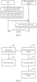
- Fig.12 is a schematic structural diagram of a communication device including a DSC function on an authorized device, and as illustrated, the communication device can include follows.
- An information determining module 1201 is configured to determine functional parameter configuration information of the DSC, where the functional parameter configuration information includes one or a combination of: a DSC device identifier, a network identifier, a cluster identifier, cluster information, a service identifier, and a core network NSC identifier or core network NSC address information.
- a demand determining module 1202 is configured to determine a communication demand on the DSC according to the functional parameter configuration information.
- An executing module 1203 is configured to transmit a communication request message to a corresponding device.
- the functional parameter configuration information includes the core network NSC identifier or the core network NSC address information
- the demand determining module is further configured to determine according to the functional parameter configuration information that the communication demand on the DSC is to establish a Me1 interface communication connection.
- the executing module is further configured to transmit a Me1 interface establishment request message to the NSC.
- the communication device further includes follows.
- An information storage module 1204 is configured to store Me1 interface establishment success state information upon reception of a Me1 interface establishment complete message returned by the NSC.
- the functional parameter configuration information includes the DSC device identifier, the network identifier, the cluster identifier, and the service identifier.
- the demand determining module is further configured to determine according to the functional parameter configuration information that the communication demand on the DSC is to broadcast in the cluster system information to be known to the devices in the cluster.
- the executing module is further configured to broadcast a system broadcast message via an air interface, where the system broadcast message includes one or a combination of the DSC device identifier, the network identifier, the cluster identifier, and the service identifier.
- the executing module is further configured to transmit the system broadcast message including forward information indicating whether the system broadcast message needs to be forwarded by the receiving device.
- the communication device further includes follows.
- a receiving module 1205 is configured to receive a Me2 interface establishment request message transmitted by another DSC, where the Me2 interface establishment request message carries one or a combination of the device identifier of the current DSC, the identifier of the current network, the identifier of the current cluster, and the identifier of a service provided by the current DSC.
- the executing module is further configured to return a Me2 interface establishment complete message to the other DSC.
- the communication device further includes follows:
- a receiving module 1205 is configured to receive a system broadcast message transmitted by another DSC, where the system broadcast message includes one or a combination of a device identifier of the other DSC, a network identifier of the other DSC, a cluster identifier of the other DSC, and a service identifier of the other DSC.
- the executing module is further configured to transmit a Me2 interface establishment request message to the other DSC, where the Me2 interface establishment request message includes one or a combination of the device identifier of the other DSC, the network identifier of the other DSC, the cluster identifier of the other DSC, and the service identifier of the other DSC.
- the receiving module is further configured to receive a Me2 interface establishment complete message returned by the other DSC.
- the receiving module is further configured to receive a system broadcast message which is transmitted by the other DSC and then forwarded by an EP, or to receive a system broadcast message transmitted by the other DSC.
- the functional parameter configuration information includes cluster information.
- the demand determining module is further configured to determine according to the functional parameter configuration information that the communication demand on the DSC is to report the cluster information to a device managing the DSC on a core network.
- the executing module is further configured to transmit a cluster state report message to the device managing the DSC on the core network, where the cluster state report message carries information about a cluster managed by the DSC.
- the communication device further includes follows.
- the executing module is further configured, if the cluster information is changed, to transmit a cluster state report message to the device managing the DSC on the core network, where the cluster state report message carries changed information about the cluster.
- the communication device further includes follows.
- the executing module is further configured to transmit a service authorization request message to a device managing the DSC on a core network after establishing a connection with the core network, where the service authorization request message carries identification information and identity verification information of the DSC.
- the receiving module is further configured to receive a service authorization response message transmitted by the device managing the DSC, where the service authorization response message carries the functional parameter configuration information.
- Fig.13 is a schematic structural diagram of a communication device on a core network, and as illustrated, the communication device can include follows.
- a message receiving module 1301 is configured to receive a communication request message transmitted by a DSC.
- a message responding module 1302 is configured to respond to the communication request message.
- the message receiving module is further configured to receive a Me1 interface establishment request message transmitted by the DSC.
- the message responding module is further configured to return a Me1 interface establishment complete message according to the communication request message.
- the message receiving module is further configured to receive a cluster state report message transmitted by the DSC, where the cluster state report message carries information about a cluster managed by the DSC.
- the message responding module is further configured to store the information about the cluster managed by the DSC, carried in the cluster state report message according to the communication request message.
- the message receiving module is further configured to receive a service authorization request message transmitted by the DSC after establishing a connection with a core network, where the service authorization request message carries identification information and identity verification information of the DSC.
- the message responding module is further configured to determine functional parameter configuration information of the DSC according to the identification information and the identity verification information of the DSC, and subscription information, and to transmit a service authorization response message to the DSC, where the service authorization response message carries the functional parameter configuration information, and the functional parameter configuration information includes one or a combination of a DSC device identifier, a network identifier, a cluster identifier, cluster information, a service identifier, and a core network NSC identifier and core network NSC address information.
- Fig.14 is a schematic structural diagram of a communication device on an EP, and as illustrated, the communication device can include follows.
- a broadcast receiving module 1401 is configured to receive a system broadcast message transmitted via an air interface, where the system broadcast message includes one or a combination of a DSC device identifier, a network identifier, a cluster identifier, and a service identifier.
- An updating module 1402 is configured to update cluster state information according to the system broadcast message.
- system broadcast message further includes forward information indicating whether the system broadcast message needs to be forwarded by the receiving device.
- the communication device further includes follows.
- a forwarding module 1403 is configured to forward the system broadcast message to another EP via the air interface upon determining according to the forward information that the system broadcast message needs to be forwarded.
- the forward information includes the largest number N of hops, and an indicator M of the number of hops, where M and N are natural numbers.
- the forwarding module is further configured, if M is less than N, to determine that the system broadcast message needs to be forwarded, and to increase M by 1 while forwarding the system broadcast message; and if M is equal to N, to determine that the system broadcast message does not need to be forwarded.
- Fig.15 is a schematic structural diagram of a DSC according to an embodiment of the invention, and as illustrated, the DSC includes follows.
- a processor 1500 is configured to read and execute program in a memory 1520 to perform following operations.
- the functional parameter configuration information includes one or a combination of: a DSC device identifier, a network identifier, a cluster identifier, cluster information, a service identifier, and a core network NSC identifier and core network NSC address information.
- a transceiver 1510 is configured to be controlled by the processor 1500 to transmit data and perform following operations.
- the functional parameter configuration information includes the core network NSC identifier or the core network NSC address information.
- the communication request message transmitted to the NS is a Me1 interface establishment request message.
- the processor can be further configured to store Me1 interface establishment success state information upon reception of a Me1 interface establishment complete message returned by the NSC.
- the functional parameter configuration information includes the DSC device identifier, the network identifier, the cluster identifier, and the service identifier.
- the communication request message transmitted to the corresponding device is a system broadcast message transmitted via an air interface, where the system broadcast message includes one or a combination of the DSC device identifier, the network identifier, the cluster identifier, and the service identifier.
- system broadcast message can further include forward information indicating whether the system broadcast message needs to be forwarded by the receiving device.
- the processor can be further configured to perform following operations.
- Me2 interface establishment request message carries one or a combination of the device identifier of the current DSC, the identifier of the current network, the identifier of the current cluster, and the identifier of a service provided by the current DSC.
- the information carried in the Me2 interface establishment request message is obtained from the system broadcast message transmitted by the current DSC.
- the processor can be further configured to perform following operations.
- system broadcast message transmitted by another DSC, where the system broadcast message includes one or a combination of a device identifier of the other DSC, a network identifier of the other DSC, a cluster identifier of the other DSC, and a service identifier of the other DSC.
- the Me2 interface establishment request message includes one or a combination of the device identifier of the other DSC, the network identifier of the other DSC, the cluster identifier of the other DSC, and the service identifier of the other DSC.
- system broadcast message transmitted by the other DSC is forwarded by an EP.
- the functional parameter configuration information includes cluster information.
- the communication demand on the DSC is to report the cluster information to a device managing the DSC on a core network.
- the processor can be further configured to transmit a cluster state report message to the device managing the DSC on the core network, where the cluster state report message carries information about a cluster managed by the DSC.
- the processor can be further configured to perform following operations.
- cluster information is changed, transmitting a cluster state report message to the device managing the DSC on the core network, where the cluster state report message carries changed information about the cluster.
- the processor can be further configured to perform following operations.
- the bus architecture can include any number of interconnecting buses and bridges to particularly link together various circuits including one or more processors represented by the processor 1500, and one or more memories represented by the memory 1520.
- the bus architecture can further link together various other circuits, e.g., prophetical devices, manostats, power management circuits, etc., all of which are well known in the art, so a further description thereof will be omitted in this context.
- the bus interface serves as an interface.
- the transceiver 1510 can be a number of elements including a transmitter and a receiver which are units for communication with various other devices over a transmission medium.
- the processor 1500 is responsible for managing the bus architecture and performing normal processes, and the memory 1520 can store data for use by the processor 1500 in performing the operations.
- Fig.16 is a schematic structural diagram of an EP according to an embodiment of the invention, and as illustrated, the EP includes following.
- a processor 1600 is configured to read and execute program in a memory 1620 to perform following operations.
- a transceiver 1610 is configured to be controlled by the processor 1600 to transmit data and perform following operations.
- system broadcast message transmitted via an air interface, where the system broadcast message includes one or a combination of a DSC device identifier, a network identifier, a cluster identifier, and a service identifier.
- system broadcast message further includes forward information indicating whether the system broadcast message needs to be forwarded by the receiving device.
- the processor can be further configured to forward the system broadcast message to another EP via the air interface upon determining according to the forward information that the system broadcast message needs to be forwarded.
- the forward information includes the largest number N of hops, and an indicator M of the number of hops, where M and N are natural numbers.
- the processor is further configured, if M is less than N, to determine that the system broadcast message needs to be forwarded, and to increase M by 1 after forwarding the system broadcast message; and if M is equal to N, to determine that the system broadcast message does not need to be forwarded.
- the bus architecture can include any number of interconnecting buses and bridges to particularly link together various circuits including one or more processors represented by the processor 1600, and one or more memories represented by the memory 1620.
- the bus architecture can further link together various other circuits, e.g., prophetical devices, manostats, power management circuits, etc., all of which are well known in the art, so a further description thereof will be omitted in this context.
- the bus interface serves as an interface.
- the transceiver 1610 can be a number of elements including a transmitter and a receiver which are units for communication with various other devices over a transmission medium.
- the user interface 1630 can also be an interface via which external or internal devices can be connected as appropriate, where the connected devices include but will not be limited to a keypad, a display, a speaker, a microphone, a joystick, etc.
- the processor 1600 is responsible for managing the bus architecture and performing normal processes, and the memory 1620 can store data for use by the processor 1600 in performing the operations.
- a solution of starting the authorized device including that the authorized device is connected with the DSC management function of the core network, and after the identity verification is passed, the DSC control functions authorizes the device to start the DSC operating mode, obtains the configuration parameters of the DSC operating mode, and finally starts the DSC operating mode.
- a solution of establishing a Me1 interface with the core network NSC after initiating DSC including that after the DSC is started, the DSC establishes the Me1 interface with the core network NSC.
- a solution of transmitting the system message over multiple hops via the air interface including that after the DSC is started, the DSC transmits the system message over multiple hops via the air interface.
- the dynamic distributed network architecture can be provided to thereby greatly reduce a burden of storage and signaling handling on the core network due to an accessing device; and the control function can be localized to thereby greatly shorten a delay in the control-plane signaling procedure. Furthermore since the DSC function is decoupled from the authorized device in terms of software and hardware, the dynamic network including the DSC and the accessing device is also characterized in high flexibility thereof.
- the embodiments of the invention can be embodied as a method, a system or a computer program product. Therefore the invention can be embodied in the form of an all-hardware embodiment, an all-software embodiment or an embodiment of software and hardware in combination. Furthermore the invention can be embodied in the form of a computer program product embodied in one or more computer useable storage mediums (including but not limited to a disk memory, an optical memory, etc.) in which computer useable program codes are contained.
- These computer program instructions can also be stored into a computer readable memory capable of directing the computer or the other programmable data processing device to operate in a specific manner so that the instructions stored in the computer readable memory create an article of manufacture including instruction means which perform the functions specified in the flow(s) of the flow chart and/or the block(s) of the block diagram.
- These computer program instructions can also be loaded onto the computer or the other programmable data processing device so that a series of operational steps are performed on the computer or the other programmable data processing device to create a computer implemented process so that the instructions executed on the computer or the other programmable device provide steps for performing the functions specified in the flow(s) of the flow chart and/or the block(s) of the block diagram.
Landscapes
- Engineering & Computer Science (AREA)
- Computer Networks & Wireless Communication (AREA)
- Signal Processing (AREA)
- Computer Security & Cryptography (AREA)
- Multimedia (AREA)
- Computer Hardware Design (AREA)
- Computing Systems (AREA)
- General Engineering & Computer Science (AREA)
- Mobile Radio Communication Systems (AREA)
Claims (11)
- Kommunikationsverfahren, das Folgendes umfasst:Empfangen (301) von funktionalen Parameterkonfigurationsinformationen eines verteilten Dienstzentrums (Distributed Service Center, DSC), das als eine Funktion zum Übertragen von Informationen mit einem Kernnetzwerk über ein Backhaul-Netzwerk konfiguriert ist, auf die autorisierte Vorrichtung durch eine autorisierte Vorrichtung, wobei die funktionalen Parameterkonfigurationsinformationen von einem Kernnetzwerk empfangen werden und eines oder eine Kombination von Folgendem umfassen: einem DSC-Vorrichtungsidentifikator, einem Netzwerkidentifikator, einem Cluster-Identifikator, Cluster-Informationen, einem Dienstidentifikator, einem Netzwerk-Dienstzentrum, einem NSC-Identifikator des Kernnetzwerks und NSC-Adressinformationen des Kernnetzwerks; wobei das NSC als eine Funktion zum Abbrechen einer Steuerebenen-Schnittstelle eines Zugangsnetzwerks zum Kernnetzwerk auf das Kernnetzwerk konfiguriert ist; wobei der Cluster durch das DSC und umgebende Endpunkte, die mit dem DSC verbunden sind, dargestellt wird,Bestimmen (302), durch die autorisierte Vorrichtung, einer Kommunikationsanforderung an das DSC gemäß den Konfigurationsinformationen der Funktionsparameter; und Übertragen (303) einer Kommunikationsanforderungenachricht durch die autorisierte Vorrichtung an eine entsprechende Vorrichtung, wobei die entsprechende Vorrichtung das NSC, die Endpunkte oder benachbarte DSCs umfasst;wobei die autorisierte Vorrichtung mit dem DSC konfiguriert ist und sich im Voraus bei einem Betreiber zur Autorisierung des DSC anmeldet; die autorisierte Vorrichtung und die Endpunkte ein dynamisches Netzwerk in einer Ad-hoc-Weise darstellen und das DSC für die Verwaltung des Netzwerks verantwortlich ist; das DSC eine Me1-Schnittstellenverbindung mit dem NSC des Kernnetzwerks einrichtet; das DSC System-Rundfunkinformationen über eine Luftschnittstelle zu den Endpunkten überträgt; das DSC ein benachbartes DSC über die Luftschnittstelle entdeckt und eine Me2-Schnittstellenverbindung mit dem benachbarten DSC einrichtet; wobei die Endpunkte Machine-Type-Communication, MTC-ähnliche Zugangsendgeräte sind.
- Verfahren nach Anspruch 1, wobei die funktionalen Parameterkonfigurationsinformationen den NSC-Identifikator oder die NSC-Adressinformationen umfassen;die an das NSC übertragene Kommunikationsanforderungsnachricht eine Me1-Schnittstellen-Einrichtungsanforderungsnachricht ist; unddas Verfahren ferner umfasst: Speichern von Informationen über den Erfolgszustand der Me1-Schnittstelleneinrichtung beim Empfang einer von dem NSC zurückgesandten Nachricht Me1-Schnittstellen-Einrichtung abgeschlossen;die funktionalen Parameterkonfigurationsinformationen den DSC-Vorrichtungsidentifikator, den Netzwerkidentifikator, den Clusteridentifikator und den Dienstidentifikator umfassen;Bestimmen (302) der Kommunikationsanforderung an das DSC gemäß den funktionalen Parameterkonfigurationsinformationen umfasst:Ausstrahlen von Systeminformationen im Cluster, die den Vorrichtungen im Cluster bekannt sein sollen; unddie an die entsprechende Vorrichtung übertragene Kommunikationsanforderungsnachricht eine über eine Luftschnittstelle übertragene Systemausstrahlungsnachricht ist, wobei die Systemausstrahlungsnachricht eine oder eine Kombination aus dem DSC-Vorrichtungsidentifikator, dem Netzwerkidentifikator, dem Clusteridentifikator und dem Dienstidentifikator umfasst;die funktionalen Parameterkonfigurationsinformationen umfassen Clusterinformationen;Bestimmen (302) der Kommunikationsanforderung an das DSC gemäß den funktionalen Parameterkonfigurationsinformationen umfasst:Berichten der Cluster-Informationen an eine Vorrichtung, die das DSC in einem Kernnetzwerk verwaltet; undeine Clusterzustandsberichtsnachricht an eine Vorrichtung übertragen wird, die das DSC in einem Kernnetzwerk verwaltet, wobei die Clusterzustandsberichtsnachricht Informationen über einen von dem DSC verwalteten Cluster trägt.
- Verfahren nach Anspruch 1, das ferner Folgendes umfasst:Empfangen einer Me2-Schnittstellen-Einrichtungsanforderungsnachricht, die durch ein anderes DSC übertragen wurde, wobei die Me2-Schnittstellen-Einrichtungsanforderungsnachricht eine oder eine Kombination aus dem Vorrichtungsidentifikator des DSC, dem Netzwerkidentifikator, dem Clusteridentifikator und dem Identifikator eines durch das DSC bereitgestellten Dienstes trägt; die Me2-Schnittstelle ist eine Schnittstelle zwischen DSCs; undRücksendung einer Nachricht Me2-Schnittstellen-Einrichtung abgeschlossen an ein anderes DSC;
oderwobei das Verfahren ferner umfasst:Empfangen einer von einem anderen DSC übertragenen Systemausstrahlungsnachricht, wobei die Systemausstrahlungsnachricht eine oder eine Kombination aus einem Vorrichtungsidentifikator eines anderen DSC, einem Netzwerkidentifikator eines anderen DSC, einem Clusteridentifikator eines anderen DSC und einem Dienstidentifikator eines anderen DSC umfasst;Übertragen einer Me2-Schnittstellen-Einrichtungsanforderungsnachricht an einen anderen DSC, wobei die Me2-Schnittstellen-Einrichtungsanforderungsnachricht eine oder eine Kombination aus dem Vorrichtungsidentifikator eines anderen DSC, dem Netzwerkidentifikator eines anderen DSC, dem Clusteridentifikator eines anderen DSC und dem Dienstidentifikator eines anderen DSC umfasst; undEmpfangen einer von einem anderen DSC zurückgesendeten Nachricht Me2-Schnittstellen-Einrichtung abgeschlossen. - Verfahren nach Anspruch 3, wobei die in der Me2-Schnittstellen-Einrichtungsanforderungsnachricht getragenen Informationen von einer von dem DSC übertragenen Systemausstrahlungsnachricht erhalten werden;
oder
die von einem anderen DSC übertragene Systemausstrahlungsnachricht von einem Endpunkt weitergeleitet wird. - Verfahren nach Anspruch 2, wobei:die Systemausstrahlungsnachricht ferner Weiterleitungsinformationen umfasst, die angeben, ob die Systemausstrahlungsnachricht von einer Empfangsvorrichtung weitergeleitet werden muss;
oderwenn die funktionalen Parameterkonfigurationsinformationen Clusterinformationen umfassen, umfasst das Verfahren ferner:
Übertragen einer Clusterzustandsberichtsnachricht an die Vorrichtung, die das DSC im Kernnetzwerk verwaltet, wenn die Clusterinformationen verändert werden, wobei die Clusterzustandsberichtsnachricht veränderte Informationen über den Cluster trägt. - Verfahren nach einem der Ansprüche 1 bis 5, das ferner Folgendes umfasst:
Übertragen einer Dienstautorisierungsanforderungsnachricht an eine Vorrichtung, die das DSC in einem Kernnetzwerk verwaltet, nach dem Einrichten einer Verbindung mit dem Kernnetzwerk, wobei die Dienstautorisierungsanforderungsnachricht Identifikationsinformationen des DSC und Identitätsverifizierungsinformationen des DSC trägt; und Empfangen einer Dienstautorisierungs-Antwortnachricht, die von der Vorrichtung, die das DSC verwaltet, wobei die Dienstautorisierungs-Antwortnachricht die funktionalen Parameterkonfigurationsinformationen trägt. - Kommunikationsverfahren, das Folgendes umfasst:Empfangen (401), durch ein Kernnetzwerk, einer von einem verteilten Dienstzentrum (Distributed Service Center, DSC), konfiguriert als eine Funktion zum Übertragen von Informationen mit einem Kernnetzwerk über ein Backhaul-Netzwerk, an eine autorisierte Vorrichtung gesendeten Kommunikationsanforderungsnachricht; undAntworten (402), durch das Kernnetzwerk, auf die Kommunikationsanforderungsnachricht;wobei die von dem DSC übertragene Kommunikationsanforderungsnachricht eine Dienstautorisierungsanforderungsnachricht ist, die von dem DSC nach dem Einrichten einer Verbindung mit dem Kernnetzwerk übertragen wird, wobei die Dienstautorisierungsanforderungsnachricht Identifikationsinformationen des DSC und Identitätsverifizierungsinformationen des DSC trägt; und Antworten (402) auf die Kommunikationsanforderungsnachricht umfasst:Bestimmen von funktionalen Parameterkonfigurationsinformationen des DSC gemäß den Identifikationsinformationen des DSC und den Identitätsverifikationsinformationen des DSC und Subskriptionsinformationen, wobei die funktionalen Parameterkonfigurationsinformationen eine oder eine Kombination aus einem DSC-Vorrichtungsidentifikator, einem Netzwerkidentifikator, einem Clusteridentifikator, Clusterinformationen, einem Dienstidentifikator und einem NSC-Identifikator eines Kernnetzwerks oder NSC-Adressinformationen des Kernnetzwerks umfassen;Übertragen einer Dienstautorisierungs-Antwortnachricht an das DSC, wobei die Dienstautorisierungs-Antwortnachricht die funktionalen Parameterkonfigurationsinformationen trägt;wobei das NSC als eine Funktion zum Abbrechen einer Steuerebenen-Schnittstelle eines Zugangsnetzwerks zum Kernnetzwerk auf das Kernnetzwerk konfiguriert ist.
- Verfahren nach Anspruch 7, wobei die von dem DSC übertragene Kommunikationsanforderungsnachricht eine Me1-Schnittstellen-Einrichtungsanforderungsnachricht ist; unddas Antworten auf die Kommunikationsanforderungsnachricht das Zurücksenden einer Nachricht Me1-Schnittstellen-Einrichtung abgeschlossen umfasst;die von dem DSC übertragene Kommunikationsanforderungsnachricht eine Clusterzustandsberichtsnachricht ist, die Informationen über einen von dem DSC verwalteten Cluster trägt; unddas Antworten auf die Kommunikationsanforderungsnachricht das Speichern von Informationen über den von dem DSC verwalteten Cluster umfasst, die in der Clusterzustandsberichtsnachricht gemäß der Kommunikationsanforderungsnachricht getragen werden.
- Kommunikationsvorrichtung, wobei die Kommunikationsvorrichtung eine autorisierte Vorrichtung ist, die Folgendes umfasst:Informationsbestimmendes Modul (1201), das dazu konfiguriert ist, funktionale Parameterkonfigurationsinformationen eines verteilten Dienstzentrums (Distributed Service Center, DSC), zu bestimmen, das als eine Funktion zum Übertragen von Informationen mit einem Kernnetzwerk über ein Backhaul-Netzwerk konfiguriert ist, auf die autorisierte Vorrichtung, wobei die funktionalen Parameterkonfigurationsinformationen von einem Kernnetzwerk empfangen werden und eines oder eine Kombination von Folgendem umfassen: einem DSC-Vorrichtungsidentifikator, einem Netzwerkidentifikator, einem Cluster-Identifikator, Cluster-Informationen, einem Dienstidentifikator, einem Netzwerk-Dienstzentrumidentifikator, NSC-Identifikator, des Kernnetzwerks und NSC-Adressinformationen des Kernnetzwerks; wobei das NSC als eine Funktion zum Abbrechen einer Steuerebenen-Schnittstelle eines Zugangsnetzwerks zum Kernnetzwerk auf das Kernnetzwerk konfiguriert ist; wobei der Cluster durch das DSC und umgebende Endpunkte, die mit dem DSC verbunden sind, dargestellt wird,ein Bedarfsbestimmungsmodul (1202), das dazu konfiguriert ist, einen Kommunikationsbedarf auf dem DSC gemäß den funktionalen Parameterkonfigurationsinformationen zu bestimmen; undein Ausführungsmodul (1203), das dazu konfiguriert ist, eine Kommunikationsanforderungsnachricht an eine entsprechende Vorrichtung zu übertragen, wobei die entsprechende Vorrichtung das NSC, die Endpunkte oder benachbarte DSCs umfasst;wobei die autorisierte Vorrichtung mit dem DSC konfiguriert ist und sich im Voraus bei einem Betreiber zur Autorisierung des DSC anmeldet; die autorisierte Vorrichtung und die Endpunkte ein dynamisches Netzwerk in einer Ad-hoc-Weise darstellen und das DSC für die Verwaltung des Netzwerks verantwortlich ist; das DSC eine Me1-Schnittstellenverbindung mit dem NSC des Kernnetzwerks einrichtet; das DSC System-Rundfunkinformationen über eine Luftschnittstelle zu den Endpunkten überträgt; das DSC ein benachbartes DSC über die Luftschnittstelle entdeckt und eine Me2-Schnittstellenverbindung mit dem benachbarten DSC einrichtet; wobei die Endpunkte Machine-Type-Communication, MTC-ähnliche Zugangsendgeräte sind.
- Vorrichtung nach Anspruch 9, wobei die funktionalen Parameterkonfigurationsinformationen den NSC-Identifikator oder die NSC-Adressinformationen umfassen; das Ausführungsmodul (1203) ferner dazu konfiguriert ist, eine Me1-Schnittstellen-Einrichtungsanforderungsnachricht an das NSC zu übertragen; und
die Vorrichtung ferner Folgendes umfasst:ein Informationsspeichermodul (1204), das dazu konfiguriert ist, beim Empfang einer von dem NSC zurückgesendeten Nachricht Me1-Schnittstellen-Einrichtung abgeschlossen, Informationen über den Erfolgszustand der Me1-Schnittstelleneinrichtung zu speichern;
oderdie funktionalen Parameterkonfigurationsinformationen den DSC-Vorrichtungsidentifikator, den Netzwerkidentifikator, den Clusteridentifikator und den Dienstidentifikator umfassen;das Anforderungsbestimmungsmodul (1202) ferner dazu konfiguriert ist, gemäß den funktionalen Parameterkonfigurationsinformationen zu bestimmen, dass die Kommunikationsanforderung an das DSC darin besteht, Systeminformationen, die in dem Cluster bekannt sind, an Vorrichtungen in dem Cluster auszustrahlen; unddas Ausführungsmodul (1203) ferner dazu konfiguriert ist, eine Systemausstrahlungsnachricht über eine Luftschnittstelle auszustrahlen, wobei die Systemausstrahlungsnachricht eine oder eine Kombination aus dem DSC-Vorrichtungsidentifikator, dem Netzwerkidentifikator, dem Clusteridentifikator und dem Dienstidentifikator umfasst;
oderdie funktionalen Parameterkonfigurationsinformationen umfassen Clusterinformationen;das Anforderungsbestimmungsmodul (1202) ferner dazu konfiguriert ist, gemäß den funktionalen Parameterkonfigurationsinformationen zu bestimmen, dass die Kommunikationsanforderung an das DSC darin besteht, die Clusterinformationen an eine Vorrichtung zu berichten, die das DSC in einem Kernnetzwerk verwaltet; unddas Ausführungsmodul (1203) ferner dazu konfiguriert ist, eine Clusterzustandsberichtsnachricht an die Vorrichtung zu übertragen, die das DSC in dem Kernnetzwerk verwaltet, wobei die Clusterzustandsberichtsnachricht Informationen über einen durch das DSC verwalteten Cluster trägt. - Vorrichtung nach Anspruch 9, wobei die Vorrichtung ferner Folgendes umfasst:ein Empfangsmodul (1205), das dazu konfiguriert ist, eine Me2-Schnittstellen-Einrichtungsanforderungsnachricht zu empfangen, die durch ein anderes DSC übertragen wurde, wobei die Me2-Schnittstellen-Einrichtungsanforderungsnachricht eine oder eine Kombination aus dem Vorrichtungsidentifikator des DSC, dem Netzwerkidentifikator, dem Clusteridentifikator und dem Identifikator eines durch das DSC bereitgestellten Dienstes trägt; die Me2-Schnittstelle eine Schnittstelle zwischen DSCs ist; unddas Ausführungsmodul (1203) ferner dazu konfiguriert ist, eine Nachricht Me2-Schnittstellen-Einrichtung abgeschlossen an ein anderes DSC zurück zu senden;
oderdie Vorrichtung ferner Folgendes umfasst:ein Empfangsmodul (1205), das dazu konfiguriert ist, eine von einem anderen DSC ausgestrahlten Systemausstrahlungsnachricht zu empfangen, wobei die Systemausstrahlungsnachricht eine oder eine Kombination aus einem Vorrichtungsidentifikator eines anderen DSC, einem Netzwerkidentifikator eines anderen DSC, einem Clusteridentifikator eines anderen DSC und einem Dienstidentifikator eines anderen DSC umfasst;das Ausführungsmodul (1203) ferner dazu konfiguriert ist, eine Me2-Schnittstellen-Einrichtungsanforderungsnachricht an ein anderes DSC zu übertragen, wobei die Me2-Schnittstellen-Einrichtungsanforderungsnachricht eine oder eine Kombination aus dem Vorrichtungsidentifikator eines anderen DSC, dem Netzwerkidentifikator eines anderen DSC, dem Clusteridentifikator eines anderen DSC und dem Dienstidentifikator eines anderen DSC umfasst; unddas Empfangsmodul (1205) ferner dazu konfiguriert ist, eine von einem anderen DSC zurückgesendete Nachricht Me2-Schnittstellen-Einrichtung abgeschlossen zu empfangen.
Applications Claiming Priority (2)
| Application Number | Priority Date | Filing Date | Title |
|---|---|---|---|
| CN201510276443.8A CN106304395B (zh) | 2015-05-26 | 2015-05-26 | 一种通信方法及设备 |
| PCT/CN2016/077556 WO2016188219A1 (zh) | 2015-05-26 | 2016-03-28 | 一种通信方法及设备 |
Publications (3)
| Publication Number | Publication Date |
|---|---|
| EP3307012A1 EP3307012A1 (de) | 2018-04-11 |
| EP3307012A4 EP3307012A4 (de) | 2018-06-27 |
| EP3307012B1 true EP3307012B1 (de) | 2024-10-30 |
Family
ID=57392394
Family Applications (1)
| Application Number | Title | Priority Date | Filing Date |
|---|---|---|---|
| EP16799108.2A Active EP3307012B1 (de) | 2015-05-26 | 2016-03-28 | Verfahren und vorrichtung für kommunikationen |
Country Status (4)
| Country | Link |
|---|---|
| US (1) | US10674338B2 (de) |
| EP (1) | EP3307012B1 (de) |
| CN (1) | CN106304395B (de) |
| WO (1) | WO2016188219A1 (de) |
Families Citing this family (8)
| Publication number | Priority date | Publication date | Assignee | Title |
|---|---|---|---|---|
| CN105956463B (zh) * | 2016-04-23 | 2019-01-11 | 腾讯科技(深圳)有限公司 | 一种设备控制方法、装置及终端 |
| EP4236388A3 (de) * | 2018-01-30 | 2023-11-15 | Panasonic Intellectual Property Corporation of America | Kommunikationsvorrichtung und steuerverfahren für eine kommunikationsvorrichtung |
| CN112491966A (zh) * | 2018-02-02 | 2021-03-12 | 华为技术有限公司 | 会话管理方法、设备及系统 |
| CN114554426B (zh) * | 2020-11-25 | 2024-07-02 | 北京中兴高达通信技术有限公司 | 呼叫方法及装置、存储介质、电子装置 |
| CN112738735B (zh) * | 2021-02-03 | 2022-05-03 | 上海交通大学 | 广播mbms传输系统和方法、核心网及接入网 |
| CN113625795A (zh) * | 2021-10-12 | 2021-11-09 | 南京诺丹工程技术有限公司 | 环境压力监控平台与方法 |
| CN115378975B (zh) * | 2022-08-23 | 2024-02-02 | 索思(苏州)医疗科技有限公司 | 信号实时处理方法、装置、电子设备以及存储介质 |
| CN116141342B (zh) * | 2023-04-23 | 2023-06-30 | 福勤智能科技(昆山)有限公司 | 分布式机器人的信息同步与任务协作方法、装置及机器人 |
Family Cites Families (11)
| Publication number | Priority date | Publication date | Assignee | Title |
|---|---|---|---|---|
| WO2009104171A2 (en) * | 2008-02-22 | 2009-08-27 | France Telecom | Dynamic clustering management |
| MY156150A (en) * | 2009-12-22 | 2016-01-15 | Interdigital Patent Holdings | Group-based machine to machine communication |
| CN102907068A (zh) * | 2010-03-09 | 2013-01-30 | 交互数字专利控股公司 | 支持机器对机器通信的方法和设备 |
| US9185530B2 (en) * | 2010-04-02 | 2015-11-10 | Interdigital Patent Holdings, Inc. | Group procedures for machine type communication devices |
| CN102164425A (zh) * | 2011-05-11 | 2011-08-24 | 大唐移动通信设备有限公司 | 一种mtc设备管理方法、系统及mtc设备 |
| US9131354B2 (en) * | 2011-09-09 | 2015-09-08 | Lg Electronics Inc. | Method for updating terminal group identifier in machine-to-machine communication |
| US9225606B2 (en) | 2013-04-03 | 2015-12-29 | Mitsubishi Electric Research Laboratories, Inc. | Method for clustering devices in machine-to-machine networks to minimize collisions |
| US9445218B2 (en) * | 2013-05-03 | 2016-09-13 | Verizon Patent And Licensing Inc. | Efficient machine to machine communications |
| US9629020B2 (en) * | 2013-05-28 | 2017-04-18 | Rivada Networks, Llc | Methods and systems for data context and management via dynamic spectrum controller and dynamic spectrum policy controller |
| US20140376426A1 (en) * | 2013-06-20 | 2014-12-25 | Gary David Boudreau | Machine type communication aggregator apparatus and method |
| CN104378730B (zh) * | 2014-11-06 | 2018-06-22 | 中国电子科技集团公司第二十八研究所 | 一种m2m业务在蜂窝无线通信系统中的接入系统 |
-
2015
- 2015-05-26 CN CN201510276443.8A patent/CN106304395B/zh active Active
-
2016
- 2016-03-28 WO PCT/CN2016/077556 patent/WO2016188219A1/zh not_active Ceased
- 2016-03-28 EP EP16799108.2A patent/EP3307012B1/de active Active
- 2016-03-28 US US15/576,771 patent/US10674338B2/en active Active
Also Published As
| Publication number | Publication date |
|---|---|
| EP3307012A4 (de) | 2018-06-27 |
| WO2016188219A1 (zh) | 2016-12-01 |
| EP3307012A1 (de) | 2018-04-11 |
| US20180302773A1 (en) | 2018-10-18 |
| US10674338B2 (en) | 2020-06-02 |
| CN106304395A (zh) | 2017-01-04 |
| CN106304395B (zh) | 2020-02-21 |
Similar Documents
| Publication | Publication Date | Title |
|---|---|---|
| EP3307012B1 (de) | Verfahren und vorrichtung für kommunikationen | |
| KR102745187B1 (ko) | 이동통신 환경에서 단말의 초기 접속 요청 메시지를 라우팅하는 방법 및 관련 파라미터 | |
| EP3577954B1 (de) | Zugriff auf ein kommunikationssystem mit netzwerk-slicing auf der basis einer vorgegebenen zugangskategorie | |
| KR102925171B1 (ko) | 무선 통신 시스템에서 일대일 통신 서비스를 제공하는 방법 및 장치 | |
| KR102742779B1 (ko) | 무선 통신 시스템에서 직접 통신 제공 방법 및 장치 | |
| WO2015090057A1 (zh) | 路由信息发送、接收的方法、装置及路由信息处理系统 | |
| CN104349303B (zh) | 设备到设备连接管理方法、装置及基站 | |
| US20240373312A1 (en) | System and method for efficient upload or download of transmission data over mobile access devices | |
| US11184875B2 (en) | Paging method and apparatus for wireless communication | |
| KR20210023299A (ko) | 무선통신 시스템에서 네트워크 서비스를 노출하는 방법 및 장치 | |
| US20230269573A1 (en) | Systems and methods for ue context management in sidelink relay scenarios | |
| CN114051742A (zh) | 通信系统中组切换的方法及装置 | |
| CN109041078A (zh) | 一种业务数据传输方法及装置 | |
| CN106303905B (zh) | 一种通信方法及设备 | |
| CN106304204B (zh) | 一种进行服务质量管理的方法和设备 | |
| CN107615817A (zh) | 近距离业务的通信路径切换方法、装置及系统 | |
| WO2022205219A1 (zh) | 中继方式的配置方法、中继通信方法、装置及设备 | |
| EP4507408A1 (de) | Informationsbestimmungsverfahren, informationssendeverfahren, kommunikationssystem, vorrichtung und vorrichtung | |
| WO2023184190A1 (zh) | 参数配置方法、装置、设备及存储介质 | |
| KR20130015963A (ko) | 지능적 서비스를 제공하는 통합 기지국 장치 및 그 방법 | |
| CN119907090A (zh) | 一种通信方法及装置 |
Legal Events
| Date | Code | Title | Description |
|---|---|---|---|
| STAA | Information on the status of an ep patent application or granted ep patent |
Free format text: STATUS: THE INTERNATIONAL PUBLICATION HAS BEEN MADE |
|
| PUAI | Public reference made under article 153(3) epc to a published international application that has entered the european phase |
Free format text: ORIGINAL CODE: 0009012 |
|
| STAA | Information on the status of an ep patent application or granted ep patent |
Free format text: STATUS: REQUEST FOR EXAMINATION WAS MADE |
|
| 17P | Request for examination filed |
Effective date: 20171222 |
|
| AK | Designated contracting states |
Kind code of ref document: A1 Designated state(s): AL AT BE BG CH CY CZ DE DK EE ES FI FR GB GR HR HU IE IS IT LI LT LU LV MC MK MT NL NO PL PT RO RS SE SI SK SM TR |
|
| AX | Request for extension of the european patent |
Extension state: BA ME |
|
| A4 | Supplementary search report drawn up and despatched |
Effective date: 20180528 |
|
| RIC1 | Information provided on ipc code assigned before grant |
Ipc: H04W 4/08 20090101ALN20180522BHEP Ipc: H04W 84/20 20090101AFI20180522BHEP |
|
| DAV | Request for validation of the european patent (deleted) | ||
| DAX | Request for extension of the european patent (deleted) | ||
| STAA | Information on the status of an ep patent application or granted ep patent |
Free format text: STATUS: EXAMINATION IS IN PROGRESS |
|
| 17Q | First examination report despatched |
Effective date: 20200507 |
|
| RAP1 | Party data changed (applicant data changed or rights of an application transferred) |
Owner name: DATANG MOBILE COMMUNICATIONS EQUIPMENT CO., LTD. |
|
| RIC1 | Information provided on ipc code assigned before grant |
Ipc: H04W 4/08 20090101ALN20240404BHEP Ipc: H04W 84/20 20090101AFI20240404BHEP |
|
| GRAP | Despatch of communication of intention to grant a patent |
Free format text: ORIGINAL CODE: EPIDOSNIGR1 |
|
| STAA | Information on the status of an ep patent application or granted ep patent |
Free format text: STATUS: GRANT OF PATENT IS INTENDED |
|
| RIC1 | Information provided on ipc code assigned before grant |
Ipc: H04W 4/08 20090101ALN20240515BHEP Ipc: H04W 84/20 20090101AFI20240515BHEP |
|
| INTG | Intention to grant announced |
Effective date: 20240529 |
|
| GRAS | Grant fee paid |
Free format text: ORIGINAL CODE: EPIDOSNIGR3 |
|
| GRAA | (expected) grant |
Free format text: ORIGINAL CODE: 0009210 |
|
| STAA | Information on the status of an ep patent application or granted ep patent |
Free format text: STATUS: THE PATENT HAS BEEN GRANTED |
|
| AK | Designated contracting states |
Kind code of ref document: B1 Designated state(s): AL AT BE BG CH CY CZ DE DK EE ES FI FR GB GR HR HU IE IS IT LI LT LU LV MC MK MT NL NO PL PT RO RS SE SI SK SM TR |
|
| REG | Reference to a national code |
Ref country code: GB Ref legal event code: FG4D |
|
| REG | Reference to a national code |
Ref country code: CH Ref legal event code: EP |
|
| REG | Reference to a national code |
Ref country code: IE Ref legal event code: FG4D |
|
| REG | Reference to a national code |
Ref country code: DE Ref legal event code: R096 Ref document number: 602016090052 Country of ref document: DE |
|
| REG | Reference to a national code |
Ref country code: LT Ref legal event code: MG9D |
|
| REG | Reference to a national code |
Ref country code: NL Ref legal event code: MP Effective date: 20241030 |
|
| PG25 | Lapsed in a contracting state [announced via postgrant information from national office to epo] |
Ref country code: IS Free format text: LAPSE BECAUSE OF FAILURE TO SUBMIT A TRANSLATION OF THE DESCRIPTION OR TO PAY THE FEE WITHIN THE PRESCRIBED TIME-LIMIT Effective date: 20250228 Ref country code: HR Free format text: LAPSE BECAUSE OF FAILURE TO SUBMIT A TRANSLATION OF THE DESCRIPTION OR TO PAY THE FEE WITHIN THE PRESCRIBED TIME-LIMIT Effective date: 20241030 Ref country code: PT Free format text: LAPSE BECAUSE OF FAILURE TO SUBMIT A TRANSLATION OF THE DESCRIPTION OR TO PAY THE FEE WITHIN THE PRESCRIBED TIME-LIMIT Effective date: 20250228 |
|
| PG25 | Lapsed in a contracting state [announced via postgrant information from national office to epo] |
Ref country code: NL Free format text: LAPSE BECAUSE OF FAILURE TO SUBMIT A TRANSLATION OF THE DESCRIPTION OR TO PAY THE FEE WITHIN THE PRESCRIBED TIME-LIMIT Effective date: 20241030 Ref country code: FI Free format text: LAPSE BECAUSE OF FAILURE TO SUBMIT A TRANSLATION OF THE DESCRIPTION OR TO PAY THE FEE WITHIN THE PRESCRIBED TIME-LIMIT Effective date: 20241030 |
|
| REG | Reference to a national code |
Ref country code: AT Ref legal event code: MK05 Ref document number: 1738215 Country of ref document: AT Kind code of ref document: T Effective date: 20241030 |
|
| PG25 | Lapsed in a contracting state [announced via postgrant information from national office to epo] |
Ref country code: BG Free format text: LAPSE BECAUSE OF FAILURE TO SUBMIT A TRANSLATION OF THE DESCRIPTION OR TO PAY THE FEE WITHIN THE PRESCRIBED TIME-LIMIT Effective date: 20241030 |
|
| PG25 | Lapsed in a contracting state [announced via postgrant information from national office to epo] |
Ref country code: ES Free format text: LAPSE BECAUSE OF FAILURE TO SUBMIT A TRANSLATION OF THE DESCRIPTION OR TO PAY THE FEE WITHIN THE PRESCRIBED TIME-LIMIT Effective date: 20241030 |
|
| PG25 | Lapsed in a contracting state [announced via postgrant information from national office to epo] |
Ref country code: NO Free format text: LAPSE BECAUSE OF FAILURE TO SUBMIT A TRANSLATION OF THE DESCRIPTION OR TO PAY THE FEE WITHIN THE PRESCRIBED TIME-LIMIT Effective date: 20250130 |
|
| PG25 | Lapsed in a contracting state [announced via postgrant information from national office to epo] |
Ref country code: GR Free format text: LAPSE BECAUSE OF FAILURE TO SUBMIT A TRANSLATION OF THE DESCRIPTION OR TO PAY THE FEE WITHIN THE PRESCRIBED TIME-LIMIT Effective date: 20250131 Ref country code: AT Free format text: LAPSE BECAUSE OF FAILURE TO SUBMIT A TRANSLATION OF THE DESCRIPTION OR TO PAY THE FEE WITHIN THE PRESCRIBED TIME-LIMIT Effective date: 20241030 Ref country code: LV Free format text: LAPSE BECAUSE OF FAILURE TO SUBMIT A TRANSLATION OF THE DESCRIPTION OR TO PAY THE FEE WITHIN THE PRESCRIBED TIME-LIMIT Effective date: 20241030 |
|
| PG25 | Lapsed in a contracting state [announced via postgrant information from national office to epo] |
Ref country code: PL Free format text: LAPSE BECAUSE OF FAILURE TO SUBMIT A TRANSLATION OF THE DESCRIPTION OR TO PAY THE FEE WITHIN THE PRESCRIBED TIME-LIMIT Effective date: 20241030 |
|
| PG25 | Lapsed in a contracting state [announced via postgrant information from national office to epo] |
Ref country code: RS Free format text: LAPSE BECAUSE OF FAILURE TO SUBMIT A TRANSLATION OF THE DESCRIPTION OR TO PAY THE FEE WITHIN THE PRESCRIBED TIME-LIMIT Effective date: 20250130 |
|
| PG25 | Lapsed in a contracting state [announced via postgrant information from national office to epo] |
Ref country code: SM Free format text: LAPSE BECAUSE OF FAILURE TO SUBMIT A TRANSLATION OF THE DESCRIPTION OR TO PAY THE FEE WITHIN THE PRESCRIBED TIME-LIMIT Effective date: 20241030 |
|
| PG25 | Lapsed in a contracting state [announced via postgrant information from national office to epo] |
Ref country code: DK Free format text: LAPSE BECAUSE OF FAILURE TO SUBMIT A TRANSLATION OF THE DESCRIPTION OR TO PAY THE FEE WITHIN THE PRESCRIBED TIME-LIMIT Effective date: 20241030 |
|
| PG25 | Lapsed in a contracting state [announced via postgrant information from national office to epo] |
Ref country code: EE Free format text: LAPSE BECAUSE OF FAILURE TO SUBMIT A TRANSLATION OF THE DESCRIPTION OR TO PAY THE FEE WITHIN THE PRESCRIBED TIME-LIMIT Effective date: 20241030 |
|
| PG25 | Lapsed in a contracting state [announced via postgrant information from national office to epo] |
Ref country code: RO Free format text: LAPSE BECAUSE OF FAILURE TO SUBMIT A TRANSLATION OF THE DESCRIPTION OR TO PAY THE FEE WITHIN THE PRESCRIBED TIME-LIMIT Effective date: 20241030 |
|
| PG25 | Lapsed in a contracting state [announced via postgrant information from national office to epo] |
Ref country code: SK Free format text: LAPSE BECAUSE OF FAILURE TO SUBMIT A TRANSLATION OF THE DESCRIPTION OR TO PAY THE FEE WITHIN THE PRESCRIBED TIME-LIMIT Effective date: 20241030 |
|
| PG25 | Lapsed in a contracting state [announced via postgrant information from national office to epo] |
Ref country code: CZ Free format text: LAPSE BECAUSE OF FAILURE TO SUBMIT A TRANSLATION OF THE DESCRIPTION OR TO PAY THE FEE WITHIN THE PRESCRIBED TIME-LIMIT Effective date: 20241030 |
|
| PG25 | Lapsed in a contracting state [announced via postgrant information from national office to epo] |
Ref country code: IT Free format text: LAPSE BECAUSE OF FAILURE TO SUBMIT A TRANSLATION OF THE DESCRIPTION OR TO PAY THE FEE WITHIN THE PRESCRIBED TIME-LIMIT Effective date: 20241030 |
|
| REG | Reference to a national code |
Ref country code: DE Ref legal event code: R097 Ref document number: 602016090052 Country of ref document: DE |
|
| PLBE | No opposition filed within time limit |
Free format text: ORIGINAL CODE: 0009261 |
|
| STAA | Information on the status of an ep patent application or granted ep patent |
Free format text: STATUS: NO OPPOSITION FILED WITHIN TIME LIMIT |
|
| PG25 | Lapsed in a contracting state [announced via postgrant information from national office to epo] |
Ref country code: SE Free format text: LAPSE BECAUSE OF FAILURE TO SUBMIT A TRANSLATION OF THE DESCRIPTION OR TO PAY THE FEE WITHIN THE PRESCRIBED TIME-LIMIT Effective date: 20241030 |
|
| 26N | No opposition filed |
Effective date: 20250731 |
|
| PG25 | Lapsed in a contracting state [announced via postgrant information from national office to epo] |
Ref country code: MC Free format text: LAPSE BECAUSE OF FAILURE TO SUBMIT A TRANSLATION OF THE DESCRIPTION OR TO PAY THE FEE WITHIN THE PRESCRIBED TIME-LIMIT Effective date: 20241030 |
|
| REG | Reference to a national code |
Ref country code: CH Ref legal event code: H13 Free format text: ST27 STATUS EVENT CODE: U-0-0-H10-H13 (AS PROVIDED BY THE NATIONAL OFFICE) Effective date: 20251023 |
|
| PG25 | Lapsed in a contracting state [announced via postgrant information from national office to epo] |
Ref country code: LU Free format text: LAPSE BECAUSE OF NON-PAYMENT OF DUE FEES Effective date: 20250328 |
|
| REG | Reference to a national code |
Ref country code: BE Ref legal event code: MM Effective date: 20250331 |
|
| PG25 | Lapsed in a contracting state [announced via postgrant information from national office to epo] |
Ref country code: BE Free format text: LAPSE BECAUSE OF NON-PAYMENT OF DUE FEES Effective date: 20250331 |
|
| PG25 | Lapsed in a contracting state [announced via postgrant information from national office to epo] |
Ref country code: CH Free format text: LAPSE BECAUSE OF NON-PAYMENT OF DUE FEES Effective date: 20250331 |
|
| PG25 | Lapsed in a contracting state [announced via postgrant information from national office to epo] |
Ref country code: IE Free format text: LAPSE BECAUSE OF NON-PAYMENT OF DUE FEES Effective date: 20250328 |
|
| PGFP | Annual fee paid to national office [announced via postgrant information from national office to epo] |
Ref country code: GB Payment date: 20260324 Year of fee payment: 11 |
|
| PGFP | Annual fee paid to national office [announced via postgrant information from national office to epo] |
Ref country code: DE Payment date: 20260319 Year of fee payment: 11 |
|
| PGFP | Annual fee paid to national office [announced via postgrant information from national office to epo] |
Ref country code: FR Payment date: 20260320 Year of fee payment: 11 |