EP3307191B1 - Interfaces et affichages utilisateur pour unités d'alimentation en flux - Google Patents
Interfaces et affichages utilisateur pour unités d'alimentation en flux Download PDFInfo
- Publication number
- EP3307191B1 EP3307191B1 EP16808440.8A EP16808440A EP3307191B1 EP 3307191 B1 EP3307191 B1 EP 3307191B1 EP 16808440 A EP16808440 A EP 16808440A EP 3307191 B1 EP3307191 B1 EP 3307191B1
- Authority
- EP
- European Patent Office
- Prior art keywords
- display
- flux supply
- supply unit
- surgeon console
- flux
- Prior art date
- Legal status (The legal status is an assumption and is not a legal conclusion. Google has not performed a legal analysis and makes no representation as to the accuracy of the status listed.)
- Active
Links
Images





Classifications
-
- A—HUMAN NECESSITIES
- A61—MEDICAL OR VETERINARY SCIENCE; HYGIENE
- A61B—DIAGNOSIS; SURGERY; IDENTIFICATION
- A61B34/00—Computer-aided surgery; Manipulators or robots specially adapted for use in surgery
- A61B34/30—Surgical robots
- A61B34/35—Surgical robots for telesurgery
-
- A—HUMAN NECESSITIES
- A61—MEDICAL OR VETERINARY SCIENCE; HYGIENE
- A61B—DIAGNOSIS; SURGERY; IDENTIFICATION
- A61B18/00—Surgical instruments, devices or methods for transferring non-mechanical forms of energy to or from the body
- A61B18/04—Surgical instruments, devices or methods for transferring non-mechanical forms of energy to or from the body by heating
- A61B18/12—Surgical instruments, devices or methods for transferring non-mechanical forms of energy to or from the body by heating by passing a current through the tissue to be heated, e.g. high-frequency current
- A61B18/14—Probes or electrodes therefor
-
- A—HUMAN NECESSITIES
- A61—MEDICAL OR VETERINARY SCIENCE; HYGIENE
- A61B—DIAGNOSIS; SURGERY; IDENTIFICATION
- A61B34/00—Computer-aided surgery; Manipulators or robots specially adapted for use in surgery
- A61B34/25—User interfaces for surgical systems
-
- A—HUMAN NECESSITIES
- A61—MEDICAL OR VETERINARY SCIENCE; HYGIENE
- A61B—DIAGNOSIS; SURGERY; IDENTIFICATION
- A61B34/00—Computer-aided surgery; Manipulators or robots specially adapted for use in surgery
- A61B34/30—Surgical robots
- A61B34/37—Leader-follower robots
-
- G—PHYSICS
- G16—INFORMATION AND COMMUNICATION TECHNOLOGY [ICT] SPECIALLY ADAPTED FOR SPECIFIC APPLICATION FIELDS
- G16H—HEALTHCARE INFORMATICS, i.e. INFORMATION AND COMMUNICATION TECHNOLOGY [ICT] SPECIALLY ADAPTED FOR THE HANDLING OR PROCESSING OF MEDICAL OR HEALTHCARE DATA
- G16H40/00—ICT specially adapted for the management or administration of healthcare resources or facilities; ICT specially adapted for the management or operation of medical equipment or devices
- G16H40/60—ICT specially adapted for the management or administration of healthcare resources or facilities; ICT specially adapted for the management or operation of medical equipment or devices for the operation of medical equipment or devices
- G16H40/67—ICT specially adapted for the management or administration of healthcare resources or facilities; ICT specially adapted for the management or operation of medical equipment or devices for the operation of medical equipment or devices for remote operation
-
- A—HUMAN NECESSITIES
- A61—MEDICAL OR VETERINARY SCIENCE; HYGIENE
- A61B—DIAGNOSIS; SURGERY; IDENTIFICATION
- A61B17/00—Surgical instruments, devices or methods
- A61B17/32—Surgical cutting instruments
- A61B17/320068—Surgical cutting instruments using mechanical vibrations, e.g. ultrasonic
-
- A—HUMAN NECESSITIES
- A61—MEDICAL OR VETERINARY SCIENCE; HYGIENE
- A61B—DIAGNOSIS; SURGERY; IDENTIFICATION
- A61B18/00—Surgical instruments, devices or methods for transferring non-mechanical forms of energy to or from the body
- A61B18/04—Surgical instruments, devices or methods for transferring non-mechanical forms of energy to or from the body by heating
- A61B18/12—Surgical instruments, devices or methods for transferring non-mechanical forms of energy to or from the body by heating by passing a current through the tissue to be heated, e.g. high-frequency current
- A61B18/14—Probes or electrodes therefor
- A61B18/1442—Probes having pivoting end effectors, e.g. forceps
- A61B18/1445—Probes having pivoting end effectors, e.g. forceps at the distal end of a shaft, e.g. forceps or scissors at the end of a rigid rod
-
- A—HUMAN NECESSITIES
- A61—MEDICAL OR VETERINARY SCIENCE; HYGIENE
- A61B—DIAGNOSIS; SURGERY; IDENTIFICATION
- A61B18/00—Surgical instruments, devices or methods for transferring non-mechanical forms of energy to or from the body
- A61B18/04—Surgical instruments, devices or methods for transferring non-mechanical forms of energy to or from the body by heating
- A61B18/12—Surgical instruments, devices or methods for transferring non-mechanical forms of energy to or from the body by heating by passing a current through the tissue to be heated, e.g. high-frequency current
- A61B18/14—Probes or electrodes therefor
- A61B18/16—Indifferent or passive electrodes for grounding
-
- A—HUMAN NECESSITIES
- A61—MEDICAL OR VETERINARY SCIENCE; HYGIENE
- A61B—DIAGNOSIS; SURGERY; IDENTIFICATION
- A61B18/00—Surgical instruments, devices or methods for transferring non-mechanical forms of energy to or from the body
- A61B18/18—Surgical instruments, devices or methods for transferring non-mechanical forms of energy to or from the body by applying electromagnetic radiation, e.g. microwaves
- A61B18/20—Surgical instruments, devices or methods for transferring non-mechanical forms of energy to or from the body by applying electromagnetic radiation, e.g. microwaves using laser
-
- A—HUMAN NECESSITIES
- A61—MEDICAL OR VETERINARY SCIENCE; HYGIENE
- A61B—DIAGNOSIS; SURGERY; IDENTIFICATION
- A61B18/00—Surgical instruments, devices or methods for transferring non-mechanical forms of energy to or from the body
- A61B2018/00571—Surgical instruments, devices or methods for transferring non-mechanical forms of energy to or from the body for achieving a particular surgical effect
- A61B2018/00595—Cauterization
-
- A—HUMAN NECESSITIES
- A61—MEDICAL OR VETERINARY SCIENCE; HYGIENE
- A61B—DIAGNOSIS; SURGERY; IDENTIFICATION
- A61B18/00—Surgical instruments, devices or methods for transferring non-mechanical forms of energy to or from the body
- A61B2018/00571—Surgical instruments, devices or methods for transferring non-mechanical forms of energy to or from the body for achieving a particular surgical effect
- A61B2018/00601—Cutting
-
- A—HUMAN NECESSITIES
- A61—MEDICAL OR VETERINARY SCIENCE; HYGIENE
- A61B—DIAGNOSIS; SURGERY; IDENTIFICATION
- A61B18/00—Surgical instruments, devices or methods for transferring non-mechanical forms of energy to or from the body
- A61B2018/00982—Surgical instruments, devices or methods for transferring non-mechanical forms of energy to or from the body combined with or comprising means for visual or photographic inspections inside the body, e.g. endoscopes
-
- A—HUMAN NECESSITIES
- A61—MEDICAL OR VETERINARY SCIENCE; HYGIENE
- A61B—DIAGNOSIS; SURGERY; IDENTIFICATION
- A61B34/00—Computer-aided surgery; Manipulators or robots specially adapted for use in surgery
- A61B34/25—User interfaces for surgical systems
- A61B2034/256—User interfaces for surgical systems having a database of accessory information, e.g. including context sensitive help or scientific articles
-
- A—HUMAN NECESSITIES
- A61—MEDICAL OR VETERINARY SCIENCE; HYGIENE
- A61B—DIAGNOSIS; SURGERY; IDENTIFICATION
- A61B2218/00—Details of surgical instruments, devices or methods for transferring non-mechanical forms of energy to or from the body
- A61B2218/001—Details of surgical instruments, devices or methods for transferring non-mechanical forms of energy to or from the body having means for irrigation and/or aspiration of substances to and/or from the surgical site
- A61B2218/002—Irrigation
-
- A—HUMAN NECESSITIES
- A61—MEDICAL OR VETERINARY SCIENCE; HYGIENE
- A61B—DIAGNOSIS; SURGERY; IDENTIFICATION
- A61B2218/00—Details of surgical instruments, devices or methods for transferring non-mechanical forms of energy to or from the body
- A61B2218/001—Details of surgical instruments, devices or methods for transferring non-mechanical forms of energy to or from the body having means for irrigation and/or aspiration of substances to and/or from the surgical site
- A61B2218/007—Aspiration
-
- A—HUMAN NECESSITIES
- A61—MEDICAL OR VETERINARY SCIENCE; HYGIENE
- A61N—ELECTROTHERAPY; MAGNETOTHERAPY; RADIATION THERAPY; ULTRASOUND THERAPY
- A61N1/00—Electrotherapy; Circuits therefor
- A61N1/18—Applying electric currents by contact electrodes
- A61N1/32—Applying electric currents by contact electrodes alternating or intermittent currents
- A61N1/36—Applying electric currents by contact electrodes alternating or intermittent currents for stimulation
- A61N1/36014—External stimulators, e.g. with patch electrodes
Definitions
- aspects of the present disclosure relate to user interfaces and/or displays for surgical flux supply units, such as, for example, surgical flux supply units used to supply flux to surgical instruments of teleoperated surgical systems.
- Remotely controlled surgical instruments including teleoperated surgical instruments (e.g., surgical instruments operated at least in part with computer assistance, such as instruments operated with robotic "master-slave” technology), are often used in minimally invasive medical procedures.
- teleoperated surgical systems surgeons manipulate input devices at a surgeon console, and those "master” inputs are passed to a patient side cart that interfaces with one or more remotely controlled surgical instruments coupled to the patient side cart. Based on the surgeon inputs at the surgeon console, the one or more remotely controlled surgical instruments are actuated at the patient side cart to operate on the patient, thereby creating a master-slave control relationship between the surgeon console and the surgical instrument(s) at the patient side cart.
- Some surgical instruments are configured to deliver a flux (e.g., laser, irrigation, suction, etc.).
- a flux e.g., laser, irrigation, suction, etc.
- Such surgical instruments are coupled to a flux supply unit, such as electrosurgical energy generating units (ESU's) in the case of an electrosurgical instrument.
- ESU electrosurgical energy generating units
- an ESU may generate and supply an electrosurgical flux energy to an electrosurgical instrument so that an electrosurgical energy may be applied to tissue at or near an end effector of the electrosurgical instrument.
- Other flux generating and supply units also may be coupled to an instrument that is configured to deliver a flux during the performance of a surgical procedure.
- flux supply units are not located at the surgeon console. Instead, they are an auxiliary piece of equipment typically located at an auxiliary control cart or the like.
- manipulation of the controls on a flux supply unit is performed by an assistant to a user at the surgeon console.
- the user typically requests the assistant to change a setting on the flux supply unit and wait for the setting to change.
- the process of requesting a setting change is repeated.
- a need exists to improve upon access to flux supply units, such as for a user at a surgeon console. Such autonomy may be desirable for minimizing the overall time of a surgical procedure. It also may be desirable to display information regarding flux supply units to a user at a surgeon console in a readily accessible, intuitive, and understandable format.
- WO 2014/176403 discloses a teleoperated medical device with a sensor that senses information representing a position of a control input out of an operator's field of view and displays the information to the operator.
- US 2013/0217967 discloses a method for a minimally invasive surgical system including capturing camera images of a surgical site; generating a graphical user interface (GUI) including a first colored border portion in a first side and a second colored border in a second side opposite the first side; and overlaying the GUI onto the captured camera images of the surgical site for display on a display device of a surgeon console.
- GUI graphical user interface
- the GUI provides information to a user regarding the first electrosurgical tool and the second tool in the surgical site that is concurrently displayed by the captured camera images.
- WO 98/25556 discloses a remote control unit for use with an ophthalmic surgical control system having push buttons and a display screen.
- the push button switches allow the remote control unit to select surgical modes, such as cauterization, phacoemulsification, irrigation/aspiration, vitrectomy and illumination, and allow controlling of mode parameters.
- the display screen is operator-selected to display either mode function parameters or a video feed from a surgical site to observe the surgical procedures performed by a surgeon.
- Exemplary embodiments of the present disclosure may solve one or more of the above-mentioned problems and/or may demonstrate one or more of the above-mentioned desirable features. Other features and/or advantages may become apparent from the description that follows.
- a surgeon console for a teleoperated surgical system includes: at least one master controller configured to control an instrument at a manipulator arm of the teleoperated surgical system; a user input mechanism configured to be actuated to command a flux supply unit to supply a flux to a surgical instrument operatively coupled to the surgeon console; and a user interface configured to display setting information of the flux supply unit, wherein the user interface comprises actuatable control features configured to change a control setting of the flux supply unit.
- a method for enabling control of a flux supply unit of a teleoperated surgical system includes: displaying setting information of the flux supply unit at a user interface located at a surgeon console of the teleoperated surgical system, the surgeon console comprising at least one master controller configured to control an instrument at a manipulator arm of the teleoperated surgical system, and the user interface comprising a single touchscreen display comprising a plurality of partitioned areas; and enabling actuation of control features at the user interface, wherein actuation of one or more of the control features alters one or more control settings of the flux supply unit.
- a surgeon console for a teleoperated surgical system includes a user input mechanism configured to be actuated to command a flux supply unit to supply a flux to a surgical instrument operatively coupled to the surgeon console; and a viewer configured to display an image of a surgical site during a surgical procedure, wherein the viewer is configured to display setting information of the flux supply unit.
- a surgeon console of a teleoperated surgical system can be integrated with a flux supply unit so as to permit the surgeon console to display setting information for one or more flux supply units associated with the teleoperated surgical system and/or remotely control one or more settings of one or more flux supply units.
- a surgeon console can include a touchscreen configured to display setting information for one or more flux supply units associated with the teleoperated surgical system. The setting information for all flux supply units may be displayed on a single display screen (e.g., all at once). Further, the touchscreen is capable of remotely changing the setting for the flux supply units.
- windows dedicated for each flux supply unit may open on the touchscreen in response to selection of a respective flux supply unit.
- a viewer of a surgeon console used to view a surgical site during a surgical procedure is configured to display the setting information for one or more flux supply units.
- electrosurgical instruments such as energy supply sources or energy generators
- an electrical flux e.g., such as electrosurgical energy for cautery procedures, which may, for example, range from 100s of volts to 1000s of volts.
- electrosurgical energy for cautery procedures which may, for example, range from 100s of volts to 1000s of volts.
- electrosurgical energy for cautery procedures which may, for example, range from 100s of volts to 1000s of volts.
- flux may be defined as a flow useful in surgical operations that is transmitted from one unit or source to another unit or source, for example, between a flux supply unit or source and a flux delivery component, such as, for example, a surgical instrument (e.g., to be delivered via end effector thereof). Therefore, it should be understood that references to flux supply units and electrosurgical energy supply units (ESU's) are not limited to sources of electrosurgical energy and other flux supply sources or generators are contemplated to fall within the scope of the present disclosure.
- ESU's electrosurgical energy supply units
- Nonlimiting examples of types of fluxes encompassed by the present disclosure, with appropriate modification to components using or transmitting the flux may include, for example, electrical energy (e.g., for cautery or nerve stimulation), laser energy, ultrasound energy, or radio frequency energy; fluids (e.g., liquids or gases); image and/or audio streams; vacuum pressure (in which case a negative pressure flux from a vacuum "source” is "delivered” to the instrument), etc.
- Nonlimiting examples of the flux source may include, for example, energy generators (including, for example, cautery electrical energy and/or nerve stimulation electrical energy generators), fluid delivery sources (e.g., for irrigation), gas supply sources, vacuum sources, etc.
- a flux supply unit as used herein can be considered as a sink (e.g., in the case of suction).
- Non-limiting, exemplary embodiments of teleoperated surgical systems with which the principles of the present disclosure may be utilized include the da Vinci ® Si (model no. IS3000) da Vinci ® Si Surgical System, Single Site da Vinci ® Surgical System, or a da Vinci ® Xi Surgical System, available from Intuitive Surgical, Inc. of Sunnyvale, California.
- the various exemplary embodiments described herein also may be used with the exemplary embodiments of teleoperated surgical systems described in, for example, U.S. Pub. No.
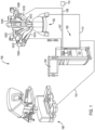
- Teleoperated surgical system 100 is configured to perform minimally invasive teleoperated surgical procedures using one or more of surgical instruments 101A, 101B, and 101D. Instruments are mounted on manipulator arms 120A, 120B, and 120D of a patient side cart 152 of system 100. Patient side cart 152 further includes an instrument 101C having an imaging device or other sensor to provide a view of a surgical site, such as by mounting instrument 101C to manipulator arm 120C. Details of various exemplary teleoperated instruments are described in the following patents and publications: U.S. Patent No. 6,840,938, published January 11, 2005 ; U.S. Patent No. 6,994,708, published February 7, 2006 ; U.S. Patent No. 7,320,700, published January 22, 2008 ; U.S. Patent No.
- Each of the instruments 101A-101D are manipulated as a "slave" device that is remotely controlled by control signals received from "master" inputs at a surgeon console 160.
- a control cable 110 may couple a computer 151 of a control cart 150 and the surgeon console 160 to control the surgical system.
- Control cart 150 further includes an assistant's display 154 to facilitate viewing of an internal surgical site.
- a control cable 111 couples the computer 151 and the patient side cart 152 for the surgeon console 160 to control the arms and instruments 101A-101D through the control cart 150, such as based upon input from a user at surgeon console 160.
- Patient side cart 152, surgeon console 160, and control cart 150 may be configured according to the exemplary embodiments of U.S. Pub. No.
- Electrosurgical instruments such as instruments 101A, 101B, and 101D, may be selected from various non-electrosurgical instruments or electrosurgical instruments.
- electrosurgical instruments and systems can be used for electrosurgical treatment of tissue during minimally invasive surgical procedures.
- Electrosurgical instruments include, for example, monopolar electrosurgical instruments and bipolar electrosurgical instruments, as well as harmonic, laser, and ultrasonic instruments. Electrosurgical instruments are capable of treating tissue with heat produced by electrical energy while cutting, shearing, grasping, engaging, or contacting treatment tissue.
- teleoperated surgical system 100 includes one or more flux supply units 102A-102N in control cart 150.
- Flux supply units can be configured as electrosurgical supply units (ESU's) and according to various exemplary embodiments herein may have settings and functions such as those disclosed in U.S. Patent No. 8,423,182, published on April 16, 2013 .
- the one or more flux supply units 102A-102N may be remotely controlled by a surgeon via surgeon console 160, as will be discussed below. Further, flux supply units 102A-102N may be used to actuate electrosurgical instruments that are mounted to the patient side cart 152 of teleoperated surgical system 100 or to actuate electrosurgical instruments not mounted to a teleoperated surgical system, such as to manually test functionality of an instrument during setup.
- one or more flux transmission conduits couple an instrument to a flux supply unit so that flux can be supplied to support and enable the functionality of the electrosurgical instrument.
- cables 106A, 106B, 107 couple instruments 101A, 101B to flux supply units, as shown in the embodiment of FIG. 1 .
- Instruments 101A, 101B may be connected to the same or to different flux supply units.
- instrument 101A is a bipolar electrosurgical instrument
- a pair of wires 106A, 106B connect instrument 101A to a flux supply unit configured as an ESU.
- instrument 101B may be a monopolar electrosurgical instrument connected to a flux supply unit configured as an ESU via a wire 107.
- a ground wire 108 is provided to couple a monopolar ESU (e.g., one of ESU's 102A-102N) and a patient (not shown).
- a monopolar ESU e.g., one of ESU's 102A-102N
- the patient may be coupled to the monopolar ESU via a grounding electrode 113, such as a pad, in contact with the body of the patient and connected to the ground wire 108.
- a grounding pad is the NESSY ® neutral electrode safety system, which is manufactured by ERBE USA, Inc. of Marietta, GA.
- a flux supply unit can include controls to facilitate use of the flux supply unit and the instruments connected to the flux supply unit.
- the flux supply units 102A'-102N' may be actuated remotely, such as via a surgeon console 160, according to the various exemplary embodiments described herein, the flux supply units 102A'-102N' include interfaces to control their settings. Such interfaces may be useful, for example, during preoperative setup according to a desired use and/or according to an instrument that is provided a flux by the flux supply unit.
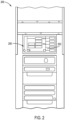
- FIG. 2 a partial view of an exemplary embodiment of a control cart 200 is shown that includes an ESU 250 as a flux supply unit.
- ESU 250 has a user control interface 252.
- the control cart 200 and ESU 250 may be arranged as described with regard to the exemplary embodiment of FIG. 1 .
- the user control interface 252 of the ESU 250 includes a display 254, a power switch 256, and one or more instrument connectors or ports 260-264 (referred to as "connectors" below) configured to supply an electrosurgical energy flux to an instrument.
- the exemplary embodiment of FIG. 3 shows five connectors 260-264, ESU 250 may include other numbers of connectors.
- an ESU may include one, two, three, four, five, or more connectors.
- Connectors 260-264 provide connections between the ESU 250 and one or more electrosurgical instruments via, for example, flux transmission conduits (e.g., cables 106A, 106B, 107 of FIG. 1 ).
- Display 254 provides a graphical user interface for a user to control and change one or more settings of the ESU 250.
- display 254 may be a touchscreen that a user may press to actuate controls and settings displayed on the touchscreen.
- a touchscreen is actuated by, for example, by being pressed by a finger of a user or other object (e.g., stylus) capable of applying a pressure to a particular area of the touchscreen.
- display 254 is partitioned into display screen sections 270-274 associated with connectors 260-264.
- the various display screen sections 270-274 display information and/or controls for different types of surgical instruments (e.g., monopolar and bipolar electrosurgical instruments).
- display 254 further includes a volume indicator 280 indicating a volume setting and a volume switch 282 configured to adjust the volume of audible output.
- Electrosurgical units of the present disclosure can be configured according the exemplary embodiments of U.S. Provisional Application No. 61/954,118 (entitled “Teleoperated Surgical System Equipment with User Interface", Atty. Dkt. No. ISRG04610PROV/US), filed March 17, 2014 .
- Surgeon consoles of the various exemplary embodiments described herein have the capability to display setting information for flux supply units (e.g., ESU's) and/or the capability to remotely control one or more settings of the flux supply units, which may be located, for example, in an auxiliary control cart of a teleoperated surgical system.
- a user of a surgeon console has enhanced autonomy during a surgical procedure by the user directly receiving the setting information and/or by having direct control over the flux supply unit settings.
- the user need not rely on an assistant to verify the settings displayed on a flux supply unit in the control cart and/or to change the settings on the flux supply unit.
- the present disclosure contemplates surgeon consoles and teleoperated surgical systems that provide information and control for a flux supply unit directly at a surgeon console, which can enable one or more settings of the flux supply unit to be changed more quickly and improve efficiency during a surgical procedure.
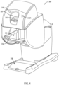
- FIG. 4 a perspective view of a surgeon console 300 for a teleoperated surgical system (e.g., system 100 of FIG. 1 ) is illustrated.
- Surgeon console 300 includes a binocular or stereo viewer 310, a left speaker 315L and a right speaker 315R, a foot pedal system 318, a viewing sensor 320, and a master input workspace 316.
- Master input workspace 316 may include an arm rest 314 and user inputs (e.g., input control for instrument end effectors, instrument wrists, and manipulator arms), (not shown) for surgical instrument control.
- Exemplary aspects of a surgeon console and its various components can be found in U.S. Patent No. 8,423,182, published on April 16, 2013 .
- FIG. 5 depicts a top view of an exemplary embodiment of foot pedal system 318 for surgical console 300.
- Pedal system 318 includes a movable pedal platform 370, a lower left pedal assembly 372L, a lower right pedal assembly 372R, a left vertical switch pedal assembly 376L, a right vertical switch pedal assembly 376R, an upper left level pedal assembly 374L, and an upper right level pedal assembly 374R.
- Each of the pedal assemblies may be assigned by the teleoperated surgical system to control a flux supply unit (e.g., ESU's 102A-102N in FIG. 1 ) that may be coupled to one or more surgical instruments (e.g., surgical instruments 101A, 101B, 101D in FIG. 1 ).
- a flux supply unit e.g., ESU's 102A-102N in FIG. 1
- surgical instruments e.g., surgical instruments 101A, 101B, 101D in FIG. 1 ).
- pedal system 318 includes a drive assembly to move the moveable pedal platform 370 over a floor.
- the pedal system 318 may further include a lift assembly to raise the moveable pedal platform above the floor when transporting the surgeon console and lower the pedal platform when the pedals are ready to be used by a user.
- FIG. 6 depicts an enlarged perspective view of the master input workspace 316 of the surgeon's console 300.
- Master input workspace 316 includes an ergonomic control panel 330 including controls for the movement of pedal platform 370 of foot pedal system 318, as well as other ergonomic positions for components of the surgeon console, according to an exemplary embodiment.
- Master input workspace 316 further includes user input devices configured to receive input to control surgical instruments associated with a teleoperated surgical system.
- master input workspace 316 includes a pair of master controllers 340L, 340R to generate control signals for the patient side cart 300 to control the manipulator arms and the surgical instruments mounted thereto.
- Left master controller 340L includes a left control input wrist 342L and a left control input grip 344L
- right master controller 340R includes a right control input wrist 342R and a right control input grip 344R, according to an exemplary embodiment.
- the arm rest 314 may include mechanisms to provide haptic feedback to a user, such as, for example, a left vibrating feedback mechanism 350L and a right vibrating feedback mechanism 350R positioned in the arm rest 314 to be under an area where a user may rest his left and right forearms.
- the surgeon console 300 further includes a touchscreen 360 mounted in the arm-rest 314.
- Touchscreen 360 is actuated by, for example, by being pressed via a user (e.g., a user's finger) or other object (e.g., stylus) capable of applying a pressure to a particular area of the touchscreen.
- Touchscreen 360 is located near the center of the arm-rest 314 between positions where a surgeon arms rest so that it is viewable during surgery and avoids unintended actuation due to the arms touching the touchscreen, although such positioning of the touchscreen 360 is exemplary and nonlimiting.
- touchscreen 360 can be used for various functions, such as, for example, to access user accounts for controlling a teleoperated surgical system.
- touchscreen 360 may be configured as a user interface to display settings for a flux supply unit and/or controls for the settings of the flux supply unit.
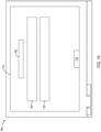
- FIG. 7 shows an exemplary touchscreen 400 for a surgeon console, such as touchscreen 360, with the touchscreen 400 in a "home" mode that displays various settings for one or more flux supply units (e.g., ESU's).
- touchscreen 400 may include various display pods 410-413 to display settings of one or more flux supply units when touchscreen 400 is in the home mode. Although four display pods 410-413 are depicted in the exemplary embodiment of FIG. 7 , touchscreen 400 may include various numbers of display pods, such as, for example, one, two, three, four, or more display pods.
- Touchscreen 400 may further include a section 414 of controls 416 (depicted schematically in FIG. 7 ) for various general functions, such as, for example, screen brightness, sound volume, microphone activation, and/or other functions. Further, touchscreen 400 includes various tabs 417-419 to permit a user to toggle between various screens, such as, for example, the home mode screen depicted in FIG. 7 , a user accounts screen, and other screens used to control functions for a teleoperated surgical system, according to an exemplary embodiment.
- controls 416 displayed schematically in FIG. 7
- touchscreen 400 includes various tabs 417-419 to permit a user to toggle between various screens, such as, for example, the home mode screen depicted in FIG. 7 , a user accounts screen, and other screens used to control functions for a teleoperated surgical system, according to an exemplary embodiment.
- touchscreen 400 may include a number of display pods corresponding to the number of manipulator arms of a patient side cart.
- display pods 410-413 may correspond to manipulator arms 120A, 120B, 120C, 120D of patient side cart 152 of FIG. 1 .
- manipulator arm identifiers 430-433 may be displayed in respective header portions 420-423 of display pods 410-413, with identifiers 430-433 corresponding to manipulators arms 120A, 120B, 120C, 120D (e.g., corresponding to a number representing a respective manipulator arm).
- Display pods 410-413 may include display portions other than header portions 420-423.
- instrument identification portions 460-463 display the type of instrument associated with a respective display pod (e.g., instruments 101A, 101B, 101C, 101D of FIG. 1 ), such as the type (e.g., "forceps," as depicted in display pod 410) or name of the instrument mounted to a manipulator arm associated with a respective display pod.
- Display pods 410-413 may further include a lock portion 470, 472, 473 to indicate that a manipulator arm (e.g., manipulator arm 120A, 120B, 120C, 120D of patient side cart 152 of FIG.
- Lock portions 470, 472, 473 therefore serve to notify a user that the lock feature is active for a manipulator arm associated with the pod in which the lock portion is displayed.
- Lock portions 470, 472, 473 may be provided for display pods 410-413 associated with surgical instruments having end effectors but not provided for a display pod associated with an instrument having a camera device or other instrument for viewing a surgical site.
- display pod 411 of touchscreen 400 may be associated with an instrument having a camera device (e.g., instrument 101C in FIG. 1 ) and therefore lack a lock portion because there is no flux supply unit associated with the camera device.
- Display pods 410-413 display settings information for one or more flux supply units associated with the respective display pods 410-413 when the touchscreen 400 is in the home mode.
- header portions 420-423 include mode identifications 440-443 listing an output mode or function selected for an associated instrument, such as via text naming the mode or function being utilized.
- mode identifications include, for example, soft coagulation (or soft coag) and auto stop ( e.g., for bipolar electrosurgical instruments), and dry cut, auto cut, force coagulation (or forced coag), and swift coagulation (or swift coag) ( e.g., for monopolar electrosurgical instruments).
- effect intensity portions 450-453 display an indication, such as, for example, a numerical value, representing an effect intensity selected for the mode or function of an associated instrument.
- display pods 410 and 412 are associated with instruments (e.g., electrosurgical instruments) having modes and effect intensities displayed in mode identification portions 440, 442 and effect intensity portions 450, 452.
- the settings shown in display pods 410 and 412 may be for the same flux supply device or for different flux supply devices (e.g., bipolar and monopolar ESUs).
- Display pod 411 is associated with an instrument having a camera device or other sensor to view a surgical site, and thus does not have a mode or intensity displayed in portions 441 and 451, while display pod 413 is not associated with an instrument (e.g., an instrument is not mounted to its associated manipulator arm) and therefore its mode identification portion 443 and effect intensity portion 453 are blank.
- FIG. 7 reflects one exemplary configuration of the instruments mounted at a patient side cart and corresponding flux supply units and that numerous other configurations are possible with corresponding modifications to display 400 and individual display pods 410-413.
- touchscreen 400 may display settings information for one or more flux supply units associated with the various instruments being used with a teleoperated surgical system on a single screen (e.g., simultaneously), such as when touchscreen is in the home mode shown in FIG. 7 .
- a user may use touchscreen 400 to readily find and verify the settings for flux supply devices associated with particular surgical instruments being used by a teleoperated surgical system, such as a surgical instrument mounted to a particular manipulator arm of a patient side cart.
- the user at a surgeon console can remotely obtain settings information without having to rely on an assistant to read the settings displayed directly on a flux supply unit, such as at a control cart of a teleoperated surgical system.
- the home mode depicted in FIG. 7 provides a user-friendly, intuitive, comprehensible mode of displaying various types of information for one or more flux supply units and associated instruments.
- display pods 410-413 may lack borders so that the home mode of touchscreen 400 has a clean, uncluttered look that facilitates finding various types of information displayed in display pods 410-413.
- the surgeon console touchscreen may be further used to remotely change the settings for one or more flux supply units at the surgeon console.
- a user accesses controls for a flux supply unit associated with that display pod, and therefore the flux supply settings for an instrument associated with that display pod.
- the controls may be accessed when conditions have been met to permit flux to be supplied to an instrument, according to an exemplary embodiment.
- a display pod may be active when (1) the type of instrument (e.g., monopolar or bipolar electrosurgical instrument) associated with a display pod (e.g., mounted to an associated manipulator arm of a patient side cart) matches the type of flux supply unit associated with the display pod (and associated with the manipulator arm the instrument is mounted to), (2) the teleoperated surgical system is configured to expect the particular flux supply unit for the instrument (e.g., the flux supplied by the flux supply unit matches the type of flux used by the instrument), and (3) no other flux supply unit is currently being used to supply flux to the instrument.
- the type of instrument e.g., monopolar or bipolar electrosurgical instrument
- the teleoperated surgical system is configured to expect the particular flux supply unit for the instrument (e.g., the flux supplied by the flux supply unit matches the type of flux used by the instrument)
- no other flux supply unit is currently being used to supply flux to the instrument
- the controls associated with the display pod may be accessed by selecting the display pod, such as by a user touching the display pod or another user interface selection mechanism familiar to persons of ordinary skill in the art.
- An active status for a display pod can be indicated in the home mode of touchscreen 400 by providing the active pod with an appearance that differs from a non-active pod. For example, an enhanced brightness, flashing, and/or change in color of all or part of the pod may be used.
- display pods 410 and 412 are shown brightly on touchscreen 400 to indicate an active status, while display pods 411 and 413 are dimmer because no controls are available for display pods 411 and 413.
- a window opens to display settings controls for a flux supply unit associated with the display pod.
- a user may select (e.g., by touching) display pod 410 of touchscreen 400 to access the controls for the associated flux supply unit.
- FIG. 8 depicts an exemplary embodiment of a control window 510 that opens within surgeon console touchscreen 500 when the display pod 410 is selected.
- Control window 510 includes a flux type indicator 512, which may be text describing the type of flux supplied by the associated flux supply unit, such as "monopolar" for monopolar energy flux in the exemplary embodiment of FIG. 8 .
- Control window 510 further includes one or more sets of controls to select a function for an output mode of an instrument receiving the flux from the associated flux supply unit.
- a first set 520 of virtual (touch-activated) buttons may be provided for selecting a function of a first mode (e.g., a cutting mode) of the instrument.
- a first mode e.g., a cutting mode
- first set 520 of virtual mode buttons can include a button 522 for a first function type of the mode (e.g., a first cutting function, such as an auto cut function) and a button 524 for a second function type of the same mode (e.g., a second cutting function, such as dry cut).
- a user at a surgeon console could select either function by selecting (e.g., touching) one of buttons 522, 524.
- the selected button, and thus function may be indicated by altering an appearance of the button, as compared to an unselected button (e.g., button 524 is unselected, as indicated by dashed lines in FIG. 8 ).
- a selection indicator 526 e.g., a dot, star, or other icon within the selected button
- button may have a brighter border or overall appearance than an unselected button with a dimmer border or overall appearance.
- a color of the selected button may differ from that of an unselected button.
- Control window 510 may further include a mode indicator 562, such as text, to indicate the type of mode associated with first set 520 of virtual buttons.
- appearances of display features such as pods, buttons, indicators, and other display features discussed herein are exemplary in nature and non-limiting. Persons having ordinary skill in the art will appreciate additional methods of altering appearances or other properties of display features to indicate a selection or other change in status.
- Some instruments may be capable of performing more than one type of mode.
- a monopolar instrument associated with control window 510 may be capable of performing cutting modes associated with first set 520 of virtual buttons and also performing coagulation or sealing modes associated with a second set 530 of virtual buttons.
- Second set 530 of virtual (touch activated) buttons can include, for example, a button 532 for a first function type (e.g., first type of coagulation, such as forced coagulation) and a button 534 (depicted by dashed lines to indicate a non-selected state) for a second function type (e.g., second type of coagulation, such as swift coagulation) of the same mode, with a selected function being indicated in a manner discussed above with regard to first set of virtual buttons 520 (e.g., via a selection indicator 536 and/or a bright border for the selected button).
- first function type e.g., first type of coagulation, such as forced coagulation
- second function type e.g., second type of coagulation, such as swift coagulation
- a selected button of the second set 530 may differ from that of an unselected button of the second set 530 to indicate to a user which button has been selected.
- a mode indicator 572 such as text, can be provided in control window 510 to indicate the type of mode associated with second set of virtual buttons 530.
- Foot pedal icons 560, 570 can represent a foot pedal used to activate the flux supply unit, and thus an associated mode.
- pedal icons 560, 570 have shapes corresponding to foot pedals of the surgeon console.
- icon 560 has a shape similar to the upper left level pedal assembly 374L or upper right level pedal assembly 374R
- icon 570 has a shape similar to lower left pedal assembly 372L or a lower right pedal assembly 372R of foot pedal system 318. This can facilitate selection of the foot pedal associated with a desired mode.
- the different types of modes may be displayed in different manners within control window 512 to facilitate distinguishing between the multiple modes.
- a first color may be used to display a first mode
- a second, differing color may be used to display the second mode.
- foot pedal icon 560 may be displayed with a first color (e.g., a yellow color or other color)
- foot pedal icon 570 is display with a second color that differs from the first color (e.g., a blue color or other color).
- an upper border portion 511 may be displayed with the first color and a lower border portion 513 may be displayed with the second color to assist a user with associating the various controls adjacent border portions 511, 513 with a particular type of instrument mode (e.g., cutting or coagulation).
- a particular type of instrument mode e.g., cutting or coagulation
- Control windows may include other types of controls than the selection of an instrument mode.
- control window 512 includes controls 552, 556 for adjusting the intensity of a selected function, such as virtual (touch-activated) buttons that can be used to increase or decrease the intensity of the output for a selected function.
- An intensity value e.g., numerical value
- effect icons 540, 542 can graphically display a selected intensity by a corresponding number of intensity markers 533, 543, which have a different brightness or color from non-highlighted intensity markers 535, 545.
- control window 510 may include measures to alert a user, such as flashing the number zero in intensity indicator 550, 560 and/or changing the coloring the border portion 511, 513 (e.g., the color orange or other color).
- intensity indicators such as intensity indicators, effect icons, and other display features discussed herein are exemplary in nature and non-limiting.
- other numbers of intensity markers may be used in a control window than depicted in the drawings.
- a numerical value may be displayed with intensity markers, as depicted in FIG. 8 , a numerical value may displayed without intensity markers, or intensity markers may be displayed without numerical values.
- a command is sent to the flux supply unit to change the setting (e.g., ESU 102A-102N in control cart 150 of FIG. 1 )
- the flux supply unit changes the settings and sends a confirmation signal to the surgeon console
- the touchscreen e.g., control window 510 or home mode of touchscreen 400
- the display of setting information at the surgeon console therefore is based on the actual settings of the flux supply unit, rather than the initial change and intention of the user changing the settings at the control window 510. If for any reason the settings do not change at the flux supply unit, the display of the setting information at the surgeon console will not change, despite a user entering new desired settings.
- an audible sound e.g., click or chime noise
- Various circumstances may cause the system to fail to accept a user's changes in settings at the control window 510.
- Exemplary circumstances include the associated instrument not being installed on an arm, the flux supply unit not being present, a cable not being connected between the instrument and the flux supply unit, an energy device conflict, a particular instrument not being a type that can be controlled by a flux supply unit, and/or the flux supply unit and connected instrument already being in an active state (e.g., the flux supply unit activated to supply flux to the instrument.
- the control window will not be accessible from the relevant display pod and a troubleshooting message is displayed to the user.
- changes to the settings of the instrument cannot be made while the instrument is in use (e.g., the flux supply unit is activated to supply flux).
- the touchscreens at the surgeon console and the flux supply unit do not respond to input.
- the display pod buttons change to disabled states and will not respond to input.
- a control window is already open, it also will cease to respond to input.
- the instrument is in following via while being activated with flux supply, the touchpads on the surgeon console and at the flux supply unit are locked from being able to input changes.
- a teleoperated surgical system includes more than one instrument of the same type (e.g., monopolar instrument) supplied by the same flux supply unit
- changing settings for the flux supply unit e.g., via control window 510) will change the settings for all instruments of the same type, according to an exemplary embodiment.
- Touchscreen 500 may provide a reminder that a change in settings affects all instruments of the same type, such as via a pop-up window including text to remind the user, when multiple instruments of the same type are supplied by the same flux supply unit.
- control window 510 can automatically close when the tab for settings controls (e.g., tab 518) is no longer active or requirements for supplying flux to an instrument are no longer valid (e.g., the corresponding display pod, such as display pod 410, is no longer active, such as due to a fault).
- tab for settings controls e.g., tab 518
- requirements for supplying flux to an instrument are no longer valid (e.g., the corresponding display pod, such as display pod 410, is no longer active, such as due to a fault).
- a control window may include controls for a single mode of an instrument and flux supply unit rather than a plurality of modes.
- FIG. 9 an exemplary control window 610 for a single mode is depicted for a surgeon console touchscreen 600.
- Control window 610 includes a flux type indicator 612, a set 630 of virtual buttons, an effect icon 640, an intensity indicator 650, intensity controls 652, and a mode indicator 672 (e.g., "bipolar" for bipolar electrosurgical energy in the exemplary embodiment of FIG. 9 ), as generally discussed above with regard to the exemplary embodiment of FIG. 8 .
- mode indicator 672 e.g., "bipolar" for bipolar electrosurgical energy in the exemplary embodiment of FIG. 9
- the set 630 of virtual buttons can include a button 632 for a first function type (e.g., type of coagulation) and a second button 634 for a function feature (e.g., auto stop). Selection of buttons 632, 634 (e.g., via touching) can be indicated as discussed above with regard to the exemplary embodiment of FIG. 8 , such as via a selection indicator 636 and/or other appearance change.
- a first function type e.g., type of coagulation
- a function feature e.g., auto stop
- Control window 610 further includes a foot pedal icon 670, as discussed above with regard to FIG. 8 , but foot pedal icon 660 is dim (shown with dashed lines in FIG. 9 ) and not active because a mode is not associated with foot pedal icon 660 in control window 610 (e.g., no controls are provided with icon 660).
- border portion 611 may be dim and not colored or have some other appearance that differs from border portion 613.
- Foot pedal icon 660 and/or border portion 613 may change in appearance (e.g. be highlighted) such as due to a change in brightness and/or color or other change in appearance.
- foot pedal icon 660 and/or border portion 613 may appear blue to indicate the type of mode associated with the controls of control window 610, according to an exemplary embodiment.
- Control window 610 can be closed via selection (touching) of a close button 614 or any area of touchscreen 600 outside of control window 610.
- a window providing troubleshooting information may be provided to assist a user with remotely correcting a problem at the surgeon console instead of attempting to correct the problem at the flux supply unit, such as at a control cart of a teleoperated surgical system.
- a troubleshooting window 710 of a surgeon console touchscreen 700 is depicted. Troubleshooting window 710 can appear automatically, such as when a fault occurs.
- a user may select a troubleshooting option in the home mode, depicted in FIG. 7 , to open troubleshooting window 710.
- Troubleshooting window 710 can include, for example, a heading 720 identifying the type of problem and one or more blocks of text 722 providing suggestions for correcting the issue. Issues that may require troubleshooting can include, but are not limited to, a flux supply unit being expected but not present; a bad connection between a flux supply unit and an instrument; flux supply units providing the same type of flux being connected; and/or any flux supply unit not supported by a teleoperated surgical system being connected.
- a user at a surgeon console can close troubleshooting window 710 by selecting (e.g., touching) a close button 714 or selecting (e.g., touching) an area of touchscreen 700 outside of troubleshooting window 710.
- Providing a touchscreen of a surgeon console with the capability to display and/or remotely control the settings for one or more flux supply units can provide a user at the surgeon console with enhanced autonomy and efficient use of time during a surgical procedure.
- Information for one or more flux supply units may be displayed at the surgeon console in other ways, such as to facilitate viewing by a user of a surgeon console during a surgical procedure.
- setting information for one or more flux supply units may be displayed by the viewer of a surgeon console during a surgical procedure.
- a surgeon console viewer can include at least one display where images of a surgical site can be viewed to perform minimally invasive surgery.
- a surgeon console viewer 800 e.g., viewer 310 of FIG. 4
- the viewer 800 includes stereo images for each eye via a left image 820L and a right image 820R of the surgical site, including any surgical instruments respectively in a left viewfinder 830L and a right viewfinder 830R.
- the images 820L and 820R in the viewfinders are provided by the left display device 810L and a right display device 810R, respectively.
- the display devices 810L, 810R may be, for example, pairs of cathode ray tube (CRT) monitors, liquid crystal displays (LCDs), or other type of image display devices (e.g., plasma, digital light projection, etc.). Images are provided in color by a pair of color display devices 810L, 810R; such as color CRTs or color LCDs.
- CTR cathode ray tube
- LCDs liquid crystal displays
- image display devices e.g., plasma, digital light projection, etc.
- a graphical user interface may be displayed in borders 840L, 840R around or near edges of each of the display devices 810L, 810R.
- the graphical user interface may be used to display settings of one or more flux supply units during a surgical procedure. This permits a user viewing a surgical site via viewer 800 of a surgeon console to view settings for the one or more flux supply units without stopping usage of viewer 800.
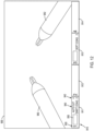
- FIG. 12 depicts an exemplary embodiment for displaying settings information for one or more flux supply units in a surgeon consider viewer.
- FIG. 12 depicts a view 900 (e.g., provided via viewer 800, 310) or image of a surgical site, including instruments 950 and 952, that a user would observe via a viewer, such as when the left image 820L and the right image 820R of viewer 800 in FIG. 11 are combined when a user looks into the display devices 810L, 810R of viewer 800.
- View 900 can include at least a portion of a border 910 (e.g., a portion of borders 840L, 840R) for displaying settings information for one or more flux supply units.
- a border 910 e.g., a portion of borders 840L, 840R
- border 910 includes a plurality of display pods 911-914, with each pod corresponding to an instrument mounted to a manipulator arm of a patient side cart, in a manner similar to display pods 410-413 of FIG. 7 .
- a pod can include a manipulator arm identifier 920, an instrument identifier 930 (e.g., text identifying an instrument name or type), a mode identifier 940 identifying the one or more modes or functions selected for a corresponding instrument, and effect intensity values 942 for the one or more modes or functions.
- Border 910 can be displayed continuously, periodically, and/or only upon a command of a user.
- a user can command display of border 910 by actuating a user input device of a surgeon console, such as, for example, a foot pedal (e.g., a master clutch or camera clutch pedal) or other input device of the foot pedal system 318 or the master input workspace 316 of the surgeon console 300 discussed above with regard to the exemplary embodiment of FIG. 4 .
- a foot pedal e.g., a master clutch or camera clutch pedal
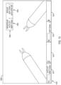
- a view 1000 e.g., provided via viewer 800, 310
- image of a surgical site that includes a border 1010 having display pods 1011-1014, as discussed above with regard to FIG. 12
- a separate display window 1020 located within view 1000.
- Display window 1020 may include, for example, settings information for pods associated with a flux supply unit, such as flux type (e.g., monopolar or bipolar electrosurgical flux), mode or function (e.g., cut or coag), and intensity (e.g., by numeric value and/or graphical indicator) for pods 1011 and 1013, with pods 1012 and 1014 not included in display window 1020 because pods 1012 and 1014 are not associated with a flux supply unit and do not display settings information.
- Display window 1020 includes the information for each of pods 1011-1014 that are active, such as pods 1011 and 1013 in FIG.
- Display window 1020 can be displayed continuously, periodically, and/or only upon a command by a user (e.g., according to the methods discussed above with regard to the exemplary embodiment of FIG. 12 ).
- View 1100 includes a border portion 1110 having display pods 1111-1114, as discussed above with regard to FIG. 12 , as well as display sections 1160, 1162 for each of the surgical instruments 1150, 1152 shown in view 1100.
- Display sections 1160 and 1162 may be generally co-located with instruments 1150 and 1152 so that as instruments 1150 and 1152 are manipulated and move, display sections 1160 and 1162 move with the instruments 1150 and 1152.
- Display sections 1160, 1162 can include settings information for the flux supply unit associated with the respective instrument 1150, 1152.
- instrument 1150 is the instrument associated with display pod 1111 and mounted to the manipulator arm identified in manipulator arm identifier 1120 of pod 1111. Therefore, display section 1160 can include, for example, the flux type, the mode or function shown in mode identifier 1140 of pod 1111, and the effect intensity values 1142 of pod 1111. Similarly, instrument 1152 may be associated with display pod 1113, so display section 1162 includes settings information of pod 1113, similar to display section 1160. According to an exemplary embodiment, display sections 1160 and 1162 may be displayed continuously, periodically, and/or upon command by a user (e.g., according to the methods discussed above with regard to the exemplary embodiment of FIG. 12 ).
- the various exemplary embodiments of the present disclosure further contemplate additional features and configurations.
- the various exemplary embodiments described herein contemplate controlling flux supply unit settings remotely at a surgeon console, settings can still be displayed and controlled at the flux supply unit itself, with updated setting displayed at the surgeon console.
- controls maybe lockable so that when locked, changes to flux supply units can only be made at the surgeon console.
- exemplary embodiments have been described with regard to the use of a single surgeon console, the present disclosure contemplates the use of more than one surgeon console.
- only one of the surgeon consoles may be configured to be capable of controlling settings for a flux supply unit (e.g., one type of flux, such as bipolar or monopolar energy) associated with the teleoperated surgical system at one time.
- a flux supply unit e.g., one type of flux, such as bipolar or monopolar energy
- a user at a first surgeon console adjusts the settings for an ESU providing monopolar energy
- a user at a second surgeon console would be unable to change the settings for the ESU.
- a message appears (e.g., as a troubleshooting window 700 on the surgeon console touchscreen) to notify the second user that only one surgeon console can change settings for the ESU at one time.
- the second user may adjust settings for the ESU when the first user is not adjusting its settings or otherwise using instruments receiving flux from the ESU, according to an exemplary embodiment.
- the present disclosure contemplates locking out the flux supply unit controls of surgeon consoles when more than one surgeon console is being used during a surgical procedure so as to limit control to only one of the surgeon consoles.
- Surgeon consoles of teleoperated surgical systems having the capability to display and/or control settings for one or more flux supply units provides a user of the surgeon console enhanced autonomy during a surgical procedure and can improve efficiency of the surgical procedure.
- a display in a surgeon console may be provided by a touchpad or touchscreen.
- the touchscreen may be, for example, a liquid crystal display (LCD).
- LCD liquid crystal display
- Such a touchscreen may be responsive to a touch pressure applied to the touchscreen, such as via a user's finder or other object, such as a stylus. For instance, a pressure may be applied to the touchscreen for a minimum time of about 5.4 milliseconds to initiate a response, which may occur within about 100 milliseconds.
- the touchscreen may be made of a scratch-resistant material and may have a diagonal size of about 13 inches or less, such as about 10.4 inches (about 264 mm) with a viewable area having a size of about 10 x 6 inches (about 254 x 152 mm), such as about 8.3 x 5.4 inches (about 212 x 138 mm). Further, the touchscreen display may have a minimum resolution of, for example, about 800 x 600 pixels and have a minimum frame rate of about 24 frames per second.
- Exemplary embodiments can be implemented in computing hardware (computing apparatus) and/or software, such as (in a non-limiting example) any computer that can store, retrieve, process and/or output data and/or communicate with other computers.
- the results produced can be displayed on a display of the computing hardware.
- One or more programs/software comprising algorithms to affect the various responses and signal processing in accordance with various exemplary embodiments of the present disclosure can be implemented by a processor, such as data interface module, of or in conjunction with the control cart including core processor and may be recorded on computer-readable media including computer-readable recording and/or storage media.
- Examples of the computer-readable recording media include a magnetic recording apparatus, an optical disk, a magneto-optical disk, and/or a semiconductor memory (for example, RAM, ROM, etc.).
- Examples of the magnetic recording apparatus include a hard disk device (HDD), a flexible disk (FD), and a magnetic tape (MT).
- Examples of the optical disk include a DVD (Digital Versatile Disc), a DVD-RAM, a CD-ROM (Compact Disc - Read Only Memory), and a CD-R (Recordable)/RW.
- spatially relative terms such as “beneath”, “below”, “lower”, “above”, “upper”, “proximal”, “distal”, and the like-may be used to describe one element's or feature's relationship to another element or feature as illustrated in the figures.
- These spatially relative terms are intended to encompass different positions (i.e., locations) and orientations (i.e., rotational placements) of a device in use or operation in addition to the position and orientation shown in the figures. For example, if a device in the figures is turned over, elements described as “below” or “beneath” other elements or features would then be “above” or “over” the other elements or features.
- the exemplary term “below” can encompass both positions and orientations of above and below.
- a device may be otherwise oriented (rotated 90 degrees or at other orientations) and the spatially relative descriptors used herein interpreted accordingly.
- the term “immediate” may mean a response that occurs within a time period of, for example, less than or equal to about 100 ms.
Landscapes
- Health & Medical Sciences (AREA)
- Engineering & Computer Science (AREA)
- Surgery (AREA)
- Life Sciences & Earth Sciences (AREA)
- Biomedical Technology (AREA)
- Medical Informatics (AREA)
- Public Health (AREA)
- General Health & Medical Sciences (AREA)
- Animal Behavior & Ethology (AREA)
- Molecular Biology (AREA)
- Heart & Thoracic Surgery (AREA)
- Nuclear Medicine, Radiotherapy & Molecular Imaging (AREA)
- Veterinary Medicine (AREA)
- Robotics (AREA)
- Physics & Mathematics (AREA)
- Plasma & Fusion (AREA)
- Otolaryngology (AREA)
- Human Computer Interaction (AREA)
- General Business, Economics & Management (AREA)
- Epidemiology (AREA)
- Primary Health Care (AREA)
- Business, Economics & Management (AREA)
- Surgical Instruments (AREA)
Claims (15)
- Console chirurgien (160, 300) pour un système chirurgical télécommandé (100), la console chirurgien comprenant :au moins un contrôleur maître (340R, 340L) configuré pour commander un instrument au niveau d'un bras de manipulation (120A, 120B, 120C, 120D) du système chirurgical télécommandé ;un mécanisme de saisie utilisateur (318) configuré pour être actionné pour envoyer à une unité d'alimentation en flux (102A, 102N, 250) une commande lui demandant de fournir un flux à un instrument chirurgical (101A, 101B, 101C, 950, 952, 1150, 1152) fonctionnellement couplé à la console chirurgien ; etcaractérisée en ce qu'elle comprend en outre une interface utilisateur (360, 400, 500, 600, 700) configurée pour afficher des informations de réglage de l'unité d'alimentation en flux, dans laquelle l'interface utilisateur comprend des éléments de commande pouvant être actionnés (416, 552, 556) configurés pour modifier un réglage de commande de l'unité d'alimentation en flux.
- Console chirurgien selon la revendication 1, dans laquelle l'interface utilisateur est configurée pour afficher simultanément des informations de réglage d'une pluralité d'unités d'alimentation en flux associées au système chirurgical télécommandé, et de préférencedans laquelle l'interface utilisateur comprend des modules d'affichage distincts (912, 914, 1011, 1012, 1013, 1014) configurés pour afficher les informations de réglage, les modules d'affichage étant contenus sur un seul affichage, et de préférencedans laquelle chacun des modules d'affichage est configuré pour afficher des informations de réglage d'un instrument chirurgical respectif et d'une unité d'alimentation en flux associée à l'instrument respectif, oudans laquelle les informations de réglage comprennent un graphique d'identification de mode d'affichage (440, 441, 442, 443, 562, 572, 672, 940, 1140) indiquant un type de mode associé à un module d'affichage respectif et un graphique d'intensité d'effet (550, 560, 650) indiquant une intensité sélectionnée pour le mode associé.
- Console chirurgien selon la revendication 1 ou la revendication 2, dans laquelle l'interface utilisateur comprend un affichage à écran tactile, et de préférencedans laquelle l'affichage à écran tactile comprend des modules d'affichage distincts configurés pour afficher simultanément des informations de réglage d'une pluralité d'unités d'alimentation en flux,dans laquelle chacun des modules d'affichage est configuré pour afficher des informations de réglage d'un instrument chirurgical respectif et d'une unité d'alimentation en flux associée à l'instrument chirurgical respectif.
- Console chirurgien selon la revendication 3, dans laquelle l'affichage à écran tactile est configuré pour ouvrir une fenêtre de commande (510, 512, 610), la fenêtre de commande comprenant des éléments de commande configurés pour ajuster le réglage d'une unité d'alimentation en flux de la pluralité d'unités d'alimentation en flux lorsqu'un module d'affichage respectif est sélectionné, et de préférencedans laquelle la fenêtre de commande comprend les éléments de commande pouvant être actionnés (416, 552, 556), dans laquelle les éléments de commande pouvant être actionnés sont configurés pour permettre la sélection d'une fonction d'instrument chirurgical, oudans laquelle la fenêtre de commande comprend les éléments de commande pouvant être actionnés, dans laquelle les éléments de commande pouvant être actionnés sont configurés pour commander l'alimentation en flux et permettre l'ajustement d'une intensité d'une fonction sélectionnée de l'instrument respectif.
- Console chirurgien selon l'une quelconque des revendications 1 à 4, dans laquelle le mécanisme de saisie utilisateur est une pédale, la pédale (318) étant configurée pour être fonctionnellement couplée à l'unité d'alimentation en flux, l'unité d'alimentation en flux étant configurée pour fournir le flux à l'instrument chirurgical en réponse à l'actionnement de la pédale,dans laquelle l'interface utilisateur comprend une fenêtre de commande configurée pour afficher une icône de pédale (560, 570, 660, 670) indiquant à un utilisateur que la pédale est fonctionnellement couplée à l'unité d'alimentation en flux, et de préférencedans laquelle la console chirurgien comprend une pluralité de pédales comprenant la pédale,dans laquelle l'icône de pédale indique à un utilisateur laquelle de la pluralité de pédales est fonctionnellement couplée à l'unité d'alimentation en flux.
- Console chirurgien selon l'une quelconque des revendications 1 à 5, dans laquelle l'interface utilisateur est située sur un accoudoir (314) de la console chirurgien.
- Console chirurgien selon l'une quelconque des revendications 1 à 6, comprenant en outre une visionneuse (310, 800) configurée pour afficher une image d'un site chirurgical au cours d'une intervention chirurgicale, et de préférencedans laquelle la visionneuse est configurée pour afficher les informations de réglage de l'unité d'alimentation en flux, et de préférencedans laquelle les informations de réglage de l'unité d'alimentation en flux sont affichées dans une bordure (511, 513, 611, 613, 840R, 840L, 910, 1010, 1110) disposée autour de l'image du site chirurgical affichée par la visionneuse, et de préférencedans laquelle la bordure comprend une pluralité de modules d'affichage distincts, dans laquelle chacun des modules d'affichage de la pluralité de modules d'affichage distincts est configuré pour afficher des informations de réglage d'un instrument chirurgical respectif d'une pluralité d'instruments chirurgicaux et d'une unité d'alimentation en flux associée à l'instrument chirurgical respectif.
- Console chirurgien selon la revendication 7, dans laquelle la visionneuse est configurée pour inclure un deuxième affichage (270, 271, 272, 273, 274, 1160, 1162) d'informations de réglage d'au moins un instrument chirurgical respectif et d'une unité d'alimentation en flux associée à un instrument respectif à l'intérieur de l'image du site chirurgical, et de préférence
dans laquelle le deuxième affichage est configuré pour afficher au moins l'un d'un mode d'instrument chirurgical, d'une fonction d'instrument chirurgical, et d'une intensité de fonction d'instrument chirurgical. - Console chirurgien selon la revendication 8, dans laquelle la visionneuse est configurée pour afficher le deuxième affichage en continu, périodiquement, ou sur commande d'un utilisateur, et de préférence
dans laquelle la visionneuse est configurée pour afficher le deuxième affichage sur commande d'un utilisateur par actionnement du mécanisme de saisie utilisateur de la console chirurgien. - Console chirurgien selon la revendication 7, dans laquelle la visionneuse est configurée pour afficher un deuxième affichage des informations de réglage de l'instrument chirurgical respectif et d'une unité d'alimentation en flux associée à l'instrument chirurgical respectif à l'intérieur de l'image du site chirurgical, dans laquelle le deuxième affichage est configuré pour être disposé à proximité de l'instrument chirurgical respectif qui peut être observé à l'intérieur de l'image.
- Console chirurgien selon l'une quelconque des revendications 1 à 10, dans laquelle l'interface utilisateur est configurée pour mettre à jour les informations de réglage affichées par l'interface utilisateur en fonction du réglage de l'unité d'alimentation en flux en cours de modification, ou
dans laquelle l'unité d'alimentation en flux est une unité d'alimentation en flux d'énergie électrochirurgicale et l'instrument chirurgical est configuré pour apporter un flux d'énergie électrochirurgicale. - Console chirurgien selon la revendication 1, comprenant en outre un écran d'affichage configuré pour afficher une image (900, 1000, 1100) d'un site chirurgical au cours d'une intervention chirurgicale, dans laquelle l'écran d'affichage est configuré pour afficher des informations de réglage de l'unité d'alimentation en flux conjointement avec l'image du site chirurgical.
- Console chirurgien selon la revendication 12, dans laquelle l'écran d'affichage est configuré pour afficher les informations de réglage de l'unité d'alimentation en flux dans une bordure (511, 513, 611, 613, 840R, 840L, 910, 1010, 1110) disposée autour de l'image du site chirurgical affichée par l'écran d'affichage.
- Procédé permettant la commande d'une unité d'alimentation en flux (102A, 102N, 250) d'un système chirurgical télécommandé (100), le procédé comprenant :l'affichage d'informations de réglage de l'unité d'alimentation en flux sur une interface utilisateur (360, 400, 500, 600, 700) située sur une console chirurgien (160, 300) du système chirurgical télécommandé, la console chirurgien comprenant au moins un contrôleur maître (340R, 340L) configuré pour commander un instrument au niveau d'un bras de manipulation (120A, 120B, 120C, 120D) du système chirurgical télécommandé, et l'interface utilisateur comprenant un seul affichage à écran tactile comprenant une pluralité de zones cloisonnées (270, 271, 272, 273, 274, 1160, 1162) ; etle fait de permettre l'actionnement d'éléments de commande (416, 552, 556) sur l'interface utilisateur, l'actionnement d'un ou plusieurs des éléments de commande modifiant un ou plusieurs réglages de commande de l'unité d'alimentation en flux.
- Procédé selon la revendication 14, dans lequel l'affichage des informations de réglage comprend un affichage simultané des informations de réglage d'une pluralité d'unités d'alimentation en flux associées au système chirurgical télécommandé, chacune de la pluralité de zones cloisonnées de l'affichage à écran tactile étant associée à l'une respective de la pluralité d'unités d'alimentation en flux, et de préférence comprenant en outre la réception d'une saisie utilisateur sur l'affichage à écran tactile pour modifier un réglage de commande de l'unité d'alimentation en flux.
Applications Claiming Priority (2)
| Application Number | Priority Date | Filing Date | Title |
|---|---|---|---|
| US201562175134P | 2015-06-12 | 2015-06-12 | |
| PCT/US2016/037020 WO2016201325A1 (fr) | 2015-06-12 | 2016-06-10 | Interfaces et affichages utilisateur pour unités d'alimentation en flux |
Publications (3)
| Publication Number | Publication Date |
|---|---|
| EP3307191A1 EP3307191A1 (fr) | 2018-04-18 |
| EP3307191A4 EP3307191A4 (fr) | 2019-02-13 |
| EP3307191B1 true EP3307191B1 (fr) | 2024-08-21 |
Family
ID=57504449
Family Applications (1)
| Application Number | Title | Priority Date | Filing Date |
|---|---|---|---|
| EP16808440.8A Active EP3307191B1 (fr) | 2015-06-12 | 2016-06-10 | Interfaces et affichages utilisateur pour unités d'alimentation en flux |
Country Status (3)
| Country | Link |
|---|---|
| US (2) | US10806531B2 (fr) |
| EP (1) | EP3307191B1 (fr) |
| WO (1) | WO2016201325A1 (fr) |
Families Citing this family (14)
| Publication number | Priority date | Publication date | Assignee | Title |
|---|---|---|---|---|
| US8332072B1 (en) | 2008-08-22 | 2012-12-11 | Titan Medical Inc. | Robotic hand controller |
| US11007029B2 (en) * | 2016-01-19 | 2021-05-18 | Titan Medical Inc. | Method and apparatus for positioning a workstation for controlling a robotic system |
| US20200038125A1 (en) * | 2017-03-15 | 2020-02-06 | Covidien Lp | Robotic surgical systems, instruments, and controls |
| WO2019051005A1 (fr) * | 2017-09-08 | 2019-03-14 | Covidien Lp | Mode de commande d'instrument à haute précision pour systèmes chirurgicaux robotiques |
| JP6898285B2 (ja) * | 2018-09-25 | 2021-07-07 | 株式会社メディカロイド | 手術システムおよび表示方法 |
| JP6856594B2 (ja) | 2018-09-25 | 2021-04-07 | 株式会社メディカロイド | 手術システムおよび表示方法 |
| JP6902639B2 (ja) * | 2018-09-25 | 2021-07-14 | 株式会社メディカロイド | 手術システム |
| US10758311B2 (en) * | 2018-10-30 | 2020-09-01 | Titan Medical Inc. | Hand controller apparatus for gesture control and shared input control in a robotic surgery system |
| USD1028250S1 (en) | 2020-11-19 | 2024-05-21 | Auris Health, Inc. | Viewer of a physician console |
| USD1003915S1 (en) * | 2021-08-19 | 2023-11-07 | Covidien Lp | Surgeon display screen with a graphical user interface having electrosurgical buttons |
| WO2023107364A1 (fr) * | 2021-12-06 | 2023-06-15 | Covidien Lp | Leviers de commande à pied d'interface utilisateur graphique pour système robotique chirurgical |
| CN118414127A (zh) * | 2021-12-17 | 2024-07-30 | 皇家飞利浦有限公司 | 通过共同配准的血管内成像控制激光斑块切除术 |
| US12079460B2 (en) * | 2022-06-28 | 2024-09-03 | Cilag Gmbh International | Profiles for modular energy system |
| US12440291B2 (en) | 2022-12-27 | 2025-10-14 | Conavi Medical Inc. | Systems and methods for unpowered release and retraction of robotic tools in a robotic surgical system |
Family Cites Families (24)
| Publication number | Priority date | Publication date | Assignee | Title |
|---|---|---|---|---|
| US6241725B1 (en) * | 1993-12-15 | 2001-06-05 | Sherwood Services Ag | High frequency thermal ablation of cancerous tumors and functional targets with image data assistance |
| US6575969B1 (en) * | 1995-05-04 | 2003-06-10 | Sherwood Services Ag | Cool-tip radiofrequency thermosurgery electrode system for tumor ablation |
| AU5514898A (en) | 1996-12-11 | 1998-07-03 | Chiron Vision Corporation | Remote control for ophthalmic surgical control console |
| US6258087B1 (en) * | 1998-02-19 | 2001-07-10 | Curon Medical, Inc. | Expandable electrode assemblies for forming lesions to treat dysfunction in sphincters and adjoining tissue regions |
| US7169141B2 (en) * | 1998-02-24 | 2007-01-30 | Hansen Medical, Inc. | Surgical instrument |
| US6840938B1 (en) | 2000-12-29 | 2005-01-11 | Intuitive Surgical, Inc. | Bipolar cauterizing instrument |
| US6994708B2 (en) | 2001-04-19 | 2006-02-07 | Intuitive Surgical | Robotic tool with monopolar electro-surgical scissors |
| US7367973B2 (en) | 2003-06-30 | 2008-05-06 | Intuitive Surgical, Inc. | Electro-surgical instrument with replaceable end-effectors and inhibited surface conduction |
| US8398634B2 (en) | 2002-04-18 | 2013-03-19 | Intuitive Surgical Operations, Inc. | Wristed robotic surgical tool for pluggable end-effectors |
| US20030040758A1 (en) * | 2001-08-21 | 2003-02-27 | Yulun Wang | Robotically controlled surgical instrument, visual force-feedback |
| EP3498213A3 (fr) | 2002-12-06 | 2019-07-03 | Intuitive Surgical Operations, Inc. | Poignée fléxible pour outil chirurgical |
| US9002518B2 (en) | 2003-06-30 | 2015-04-07 | Intuitive Surgical Operations, Inc. | Maximum torque driving of robotic surgical tools in robotic surgical systems |
| US20110125149A1 (en) | 2007-02-06 | 2011-05-26 | Rizk El-Galley | Universal surgical function control system |
| US8454531B2 (en) | 2007-11-20 | 2013-06-04 | Devicor Medical Products, Inc. | Icon-based user interface on biopsy system control module |
| US8418073B2 (en) | 2009-03-09 | 2013-04-09 | Intuitive Surgical Operations, Inc. | User interfaces for electrosurgical tools in robotic surgical systems |
| US8120301B2 (en) * | 2009-03-09 | 2012-02-21 | Intuitive Surgical Operations, Inc. | Ergonomic surgeon control console in robotic surgical systems |
| US8423182B2 (en) | 2009-03-09 | 2013-04-16 | Intuitive Surgical Operations, Inc. | Adaptable integrated energy control system for electrosurgical tools in robotic surgical systems |
| WO2011052390A1 (fr) * | 2009-10-28 | 2011-05-05 | オリンパスメディカルシステムズ株式会社 | Dispositif médical |
| US20120245575A1 (en) * | 2011-03-23 | 2012-09-27 | Halt Medical Inc. | User interface and navigational tool for remote control of an anchored rf ablation device for destruction of tissue masses |
| US9295524B2 (en) | 2012-06-01 | 2016-03-29 | Intuitive Surgical Operations, Inc. | Redundant axis and degree of freedom for hardware-constrained remote center robotic manipulator |
| KR102366082B1 (ko) | 2012-06-01 | 2022-02-23 | 인튜어티브 서지컬 오퍼레이션즈 인코포레이티드 | 멀티포트 수술 로봇 시스템 구조 |
| KR102335797B1 (ko) * | 2012-09-17 | 2021-12-07 | 인튜어티브 서지컬 오퍼레이션즈 인코포레이티드 | 원격조작 수술 기구 기능들에 입력 장치들을 할당하는 방법 및 시스템 |
| KR20160008172A (ko) | 2013-04-25 | 2016-01-21 | 인튜어티브 서지컬 오퍼레이션즈 인코포레이티드 | 수술 장비 제어 입력 시각화 장치 및 방법 |
| US10166061B2 (en) | 2014-03-17 | 2019-01-01 | Intuitive Surgical Operations, Inc. | Teleoperated surgical system equipment with user interface |
-
2016
- 2016-06-10 US US15/580,785 patent/US10806531B2/en active Active
- 2016-06-10 EP EP16808440.8A patent/EP3307191B1/fr active Active
- 2016-06-10 WO PCT/US2016/037020 patent/WO2016201325A1/fr not_active Ceased
-
2020
- 2020-10-05 US US17/062,687 patent/US20210085408A1/en not_active Abandoned
Also Published As
| Publication number | Publication date |
|---|---|
| US20180221100A1 (en) | 2018-08-09 |
| EP3307191A1 (fr) | 2018-04-18 |
| WO2016201325A1 (fr) | 2016-12-15 |
| US10806531B2 (en) | 2020-10-20 |
| EP3307191A4 (fr) | 2019-02-13 |
| US20210085408A1 (en) | 2021-03-25 |
Similar Documents
| Publication | Publication Date | Title |
|---|---|---|
| EP3307191B1 (fr) | Interfaces et affichages utilisateur pour unités d'alimentation en flux | |
| US11931092B2 (en) | Teleoperated surgical system equipment with user interface | |
| US12491037B2 (en) | Adaptable integrated energy control system for electrosurgical tools in robotic surgical systems | |
| US11166758B2 (en) | Methods of user interfaces for electrosurgical tools in robotic surgical systems | |
| US11160622B2 (en) | Methods and systems for assigning input devices to teleoperated surgical instrument functions | |
| US8120301B2 (en) | Ergonomic surgeon control console in robotic surgical systems | |
| US10335242B2 (en) | Indicator for tool state and communication in multi-arm robotic telesurgery | |
| EP3934556A1 (fr) | Appareil de commande à fonction auxiliaire pour dispositifs médicaux, et systèmes, et procédés associés |
Legal Events
| Date | Code | Title | Description |
|---|---|---|---|
| STAA | Information on the status of an ep patent application or granted ep patent |
Free format text: STATUS: THE INTERNATIONAL PUBLICATION HAS BEEN MADE |
|
| PUAI | Public reference made under article 153(3) epc to a published international application that has entered the european phase |
Free format text: ORIGINAL CODE: 0009012 |
|
| STAA | Information on the status of an ep patent application or granted ep patent |
Free format text: STATUS: REQUEST FOR EXAMINATION WAS MADE |
|
| 17P | Request for examination filed |
Effective date: 20171212 |
|
| AK | Designated contracting states |
Kind code of ref document: A1 Designated state(s): AL AT BE BG CH CY CZ DE DK EE ES FI FR GB GR HR HU IE IS IT LI LT LU LV MC MK MT NL NO PL PT RO RS SE SI SK SM TR |
|
| AX | Request for extension of the european patent |
Extension state: BA ME |
|
| DAV | Request for validation of the european patent (deleted) | ||
| DAX | Request for extension of the european patent (deleted) | ||
| A4 | Supplementary search report drawn up and despatched |
Effective date: 20190114 |
|
| RIC1 | Information provided on ipc code assigned before grant |
Ipc: A61B 34/37 20160101ALI20190108BHEP Ipc: A61B 34/00 20160101AFI20190108BHEP Ipc: A61B 18/14 20060101ALI20190108BHEP Ipc: A61B 34/35 20160101ALI20190108BHEP |
|
| STAA | Information on the status of an ep patent application or granted ep patent |
Free format text: STATUS: EXAMINATION IS IN PROGRESS |
|
| 17Q | First examination report despatched |
Effective date: 20220629 |
|
| P01 | Opt-out of the competence of the unified patent court (upc) registered |
Effective date: 20230510 |
|
| GRAP | Despatch of communication of intention to grant a patent |
Free format text: ORIGINAL CODE: EPIDOSNIGR1 |
|
| STAA | Information on the status of an ep patent application or granted ep patent |
Free format text: STATUS: GRANT OF PATENT IS INTENDED |
|
| INTG | Intention to grant announced |
Effective date: 20231109 |
|
| GRAJ | Information related to disapproval of communication of intention to grant by the applicant or resumption of examination proceedings by the epo deleted |
Free format text: ORIGINAL CODE: EPIDOSDIGR1 |
|
| STAA | Information on the status of an ep patent application or granted ep patent |
Free format text: STATUS: EXAMINATION IS IN PROGRESS |
|
| GRAP | Despatch of communication of intention to grant a patent |
Free format text: ORIGINAL CODE: EPIDOSNIGR1 |
|
| STAA | Information on the status of an ep patent application or granted ep patent |
Free format text: STATUS: GRANT OF PATENT IS INTENDED |
|
| INTC | Intention to grant announced (deleted) | ||
| INTG | Intention to grant announced |
Effective date: 20240328 |
|
| GRAS | Grant fee paid |
Free format text: ORIGINAL CODE: EPIDOSNIGR3 |
|
| GRAA | (expected) grant |
Free format text: ORIGINAL CODE: 0009210 |
|
| STAA | Information on the status of an ep patent application or granted ep patent |
Free format text: STATUS: THE PATENT HAS BEEN GRANTED |
|
| AK | Designated contracting states |
Kind code of ref document: B1 Designated state(s): AL AT BE BG CH CY CZ DE DK EE ES FI FR GB GR HR HU IE IS IT LI LT LU LV MC MK MT NL NO PL PT RO RS SE SI SK SM TR |
|
| REG | Reference to a national code |
Ref country code: GB Ref legal event code: FG4D |
|
| REG | Reference to a national code |
Ref country code: CH Ref legal event code: EP |
|
| REG | Reference to a national code |
Ref country code: IE Ref legal event code: FG4D |
|
| REG | Reference to a national code |
Ref country code: DE Ref legal event code: R096 Ref document number: 602016089022 Country of ref document: DE |
|
| REG | Reference to a national code |
Ref country code: LT Ref legal event code: MG9D |
|
| REG | Reference to a national code |
Ref country code: NL Ref legal event code: MP Effective date: 20240821 |
|
| PG25 | Lapsed in a contracting state [announced via postgrant information from national office to epo] |
Ref country code: NO Free format text: LAPSE BECAUSE OF FAILURE TO SUBMIT A TRANSLATION OF THE DESCRIPTION OR TO PAY THE FEE WITHIN THE PRESCRIBED TIME-LIMIT Effective date: 20241121 |
|
| REG | Reference to a national code |
Ref country code: AT Ref legal event code: MK05 Ref document number: 1714739 Country of ref document: AT Kind code of ref document: T Effective date: 20240821 |
|
| PG25 | Lapsed in a contracting state [announced via postgrant information from national office to epo] |
Ref country code: GR Free format text: LAPSE BECAUSE OF FAILURE TO SUBMIT A TRANSLATION OF THE DESCRIPTION OR TO PAY THE FEE WITHIN THE PRESCRIBED TIME-LIMIT Effective date: 20241122 Ref country code: PL Free format text: LAPSE BECAUSE OF FAILURE TO SUBMIT A TRANSLATION OF THE DESCRIPTION OR TO PAY THE FEE WITHIN THE PRESCRIBED TIME-LIMIT Effective date: 20240821 Ref country code: FI Free format text: LAPSE BECAUSE OF FAILURE TO SUBMIT A TRANSLATION OF THE DESCRIPTION OR TO PAY THE FEE WITHIN THE PRESCRIBED TIME-LIMIT Effective date: 20240821 Ref country code: PT Free format text: LAPSE BECAUSE OF FAILURE TO SUBMIT A TRANSLATION OF THE DESCRIPTION OR TO PAY THE FEE WITHIN THE PRESCRIBED TIME-LIMIT Effective date: 20241223 Ref country code: NL Free format text: LAPSE BECAUSE OF FAILURE TO SUBMIT A TRANSLATION OF THE DESCRIPTION OR TO PAY THE FEE WITHIN THE PRESCRIBED TIME-LIMIT Effective date: 20240821 |
|
| PG25 | Lapsed in a contracting state [announced via postgrant information from national office to epo] |
Ref country code: BG Free format text: LAPSE BECAUSE OF FAILURE TO SUBMIT A TRANSLATION OF THE DESCRIPTION OR TO PAY THE FEE WITHIN THE PRESCRIBED TIME-LIMIT Effective date: 20240821 |
|
| PG25 | Lapsed in a contracting state [announced via postgrant information from national office to epo] |
Ref country code: LV Free format text: LAPSE BECAUSE OF FAILURE TO SUBMIT A TRANSLATION OF THE DESCRIPTION OR TO PAY THE FEE WITHIN THE PRESCRIBED TIME-LIMIT Effective date: 20240821 |
|
| PG25 | Lapsed in a contracting state [announced via postgrant information from national office to epo] |
Ref country code: AT Free format text: LAPSE BECAUSE OF FAILURE TO SUBMIT A TRANSLATION OF THE DESCRIPTION OR TO PAY THE FEE WITHIN THE PRESCRIBED TIME-LIMIT Effective date: 20240821 Ref country code: IS Free format text: LAPSE BECAUSE OF FAILURE TO SUBMIT A TRANSLATION OF THE DESCRIPTION OR TO PAY THE FEE WITHIN THE PRESCRIBED TIME-LIMIT Effective date: 20241221 |
|
| PG25 | Lapsed in a contracting state [announced via postgrant information from national office to epo] |
Ref country code: HR Free format text: LAPSE BECAUSE OF FAILURE TO SUBMIT A TRANSLATION OF THE DESCRIPTION OR TO PAY THE FEE WITHIN THE PRESCRIBED TIME-LIMIT Effective date: 20240821 |
|
| PG25 | Lapsed in a contracting state [announced via postgrant information from national office to epo] |
Ref country code: RS Free format text: LAPSE BECAUSE OF FAILURE TO SUBMIT A TRANSLATION OF THE DESCRIPTION OR TO PAY THE FEE WITHIN THE PRESCRIBED TIME-LIMIT Effective date: 20241121 Ref country code: ES Free format text: LAPSE BECAUSE OF FAILURE TO SUBMIT A TRANSLATION OF THE DESCRIPTION OR TO PAY THE FEE WITHIN THE PRESCRIBED TIME-LIMIT Effective date: 20240821 |
|
| PG25 | Lapsed in a contracting state [announced via postgrant information from national office to epo] |
Ref country code: RS Free format text: LAPSE BECAUSE OF FAILURE TO SUBMIT A TRANSLATION OF THE DESCRIPTION OR TO PAY THE FEE WITHIN THE PRESCRIBED TIME-LIMIT Effective date: 20241121 Ref country code: PT Free format text: LAPSE BECAUSE OF FAILURE TO SUBMIT A TRANSLATION OF THE DESCRIPTION OR TO PAY THE FEE WITHIN THE PRESCRIBED TIME-LIMIT Effective date: 20241223 Ref country code: PL Free format text: LAPSE BECAUSE OF FAILURE TO SUBMIT A TRANSLATION OF THE DESCRIPTION OR TO PAY THE FEE WITHIN THE PRESCRIBED TIME-LIMIT Effective date: 20240821 Ref country code: NO Free format text: LAPSE BECAUSE OF FAILURE TO SUBMIT A TRANSLATION OF THE DESCRIPTION OR TO PAY THE FEE WITHIN THE PRESCRIBED TIME-LIMIT Effective date: 20241121 Ref country code: NL Free format text: LAPSE BECAUSE OF FAILURE TO SUBMIT A TRANSLATION OF THE DESCRIPTION OR TO PAY THE FEE WITHIN THE PRESCRIBED TIME-LIMIT Effective date: 20240821 Ref country code: LV Free format text: LAPSE BECAUSE OF FAILURE TO SUBMIT A TRANSLATION OF THE DESCRIPTION OR TO PAY THE FEE WITHIN THE PRESCRIBED TIME-LIMIT Effective date: 20240821 Ref country code: IS Free format text: LAPSE BECAUSE OF FAILURE TO SUBMIT A TRANSLATION OF THE DESCRIPTION OR TO PAY THE FEE WITHIN THE PRESCRIBED TIME-LIMIT Effective date: 20241221 Ref country code: HR Free format text: LAPSE BECAUSE OF FAILURE TO SUBMIT A TRANSLATION OF THE DESCRIPTION OR TO PAY THE FEE WITHIN THE PRESCRIBED TIME-LIMIT Effective date: 20240821 Ref country code: GR Free format text: LAPSE BECAUSE OF FAILURE TO SUBMIT A TRANSLATION OF THE DESCRIPTION OR TO PAY THE FEE WITHIN THE PRESCRIBED TIME-LIMIT Effective date: 20241122 Ref country code: FI Free format text: LAPSE BECAUSE OF FAILURE TO SUBMIT A TRANSLATION OF THE DESCRIPTION OR TO PAY THE FEE WITHIN THE PRESCRIBED TIME-LIMIT Effective date: 20240821 Ref country code: ES Free format text: LAPSE BECAUSE OF FAILURE TO SUBMIT A TRANSLATION OF THE DESCRIPTION OR TO PAY THE FEE WITHIN THE PRESCRIBED TIME-LIMIT Effective date: 20240821 Ref country code: BG Free format text: LAPSE BECAUSE OF FAILURE TO SUBMIT A TRANSLATION OF THE DESCRIPTION OR TO PAY THE FEE WITHIN THE PRESCRIBED TIME-LIMIT Effective date: 20240821 Ref country code: AT Free format text: LAPSE BECAUSE OF FAILURE TO SUBMIT A TRANSLATION OF THE DESCRIPTION OR TO PAY THE FEE WITHIN THE PRESCRIBED TIME-LIMIT Effective date: 20240821 |
|
| PG25 | Lapsed in a contracting state [announced via postgrant information from national office to epo] |
Ref country code: DK Free format text: LAPSE BECAUSE OF FAILURE TO SUBMIT A TRANSLATION OF THE DESCRIPTION OR TO PAY THE FEE WITHIN THE PRESCRIBED TIME-LIMIT Effective date: 20240821 Ref country code: RO Free format text: LAPSE BECAUSE OF FAILURE TO SUBMIT A TRANSLATION OF THE DESCRIPTION OR TO PAY THE FEE WITHIN THE PRESCRIBED TIME-LIMIT Effective date: 20240821 Ref country code: SM Free format text: LAPSE BECAUSE OF FAILURE TO SUBMIT A TRANSLATION OF THE DESCRIPTION OR TO PAY THE FEE WITHIN THE PRESCRIBED TIME-LIMIT Effective date: 20240821 |
|
| PG25 | Lapsed in a contracting state [announced via postgrant information from national office to epo] |
Ref country code: EE Free format text: LAPSE BECAUSE OF FAILURE TO SUBMIT A TRANSLATION OF THE DESCRIPTION OR TO PAY THE FEE WITHIN THE PRESCRIBED TIME-LIMIT Effective date: 20240821 |
|
| PG25 | Lapsed in a contracting state [announced via postgrant information from national office to epo] |
Ref country code: CZ Free format text: LAPSE BECAUSE OF FAILURE TO SUBMIT A TRANSLATION OF THE DESCRIPTION OR TO PAY THE FEE WITHIN THE PRESCRIBED TIME-LIMIT Effective date: 20240821 |
|
| PG25 | Lapsed in a contracting state [announced via postgrant information from national office to epo] |
Ref country code: IT Free format text: LAPSE BECAUSE OF FAILURE TO SUBMIT A TRANSLATION OF THE DESCRIPTION OR TO PAY THE FEE WITHIN THE PRESCRIBED TIME-LIMIT Effective date: 20240821 Ref country code: SK Free format text: LAPSE BECAUSE OF FAILURE TO SUBMIT A TRANSLATION OF THE DESCRIPTION OR TO PAY THE FEE WITHIN THE PRESCRIBED TIME-LIMIT Effective date: 20240821 |
|
| REG | Reference to a national code |
Ref country code: DE Ref legal event code: R097 Ref document number: 602016089022 Country of ref document: DE |
|
| PLBE | No opposition filed within time limit |
Free format text: ORIGINAL CODE: 0009261 |
|
| STAA | Information on the status of an ep patent application or granted ep patent |
Free format text: STATUS: NO OPPOSITION FILED WITHIN TIME LIMIT |
|
| PGFP | Annual fee paid to national office [announced via postgrant information from national office to epo] |
Ref country code: DE Payment date: 20250626 Year of fee payment: 10 |
|
| PGFP | Annual fee paid to national office [announced via postgrant information from national office to epo] |
Ref country code: GB Payment date: 20250617 Year of fee payment: 10 |
|
| PGFP | Annual fee paid to national office [announced via postgrant information from national office to epo] |
Ref country code: FR Payment date: 20250624 Year of fee payment: 10 |
|
| 26N | No opposition filed |
Effective date: 20250522 |
|
| PG25 | Lapsed in a contracting state [announced via postgrant information from national office to epo] |
Ref country code: SE Free format text: LAPSE BECAUSE OF FAILURE TO SUBMIT A TRANSLATION OF THE DESCRIPTION OR TO PAY THE FEE WITHIN THE PRESCRIBED TIME-LIMIT Effective date: 20240821 |
|
| REG | Reference to a national code |
Ref country code: CH Ref legal event code: H13 Free format text: ST27 STATUS EVENT CODE: U-0-0-H10-H13 (AS PROVIDED BY THE NATIONAL OFFICE) Effective date: 20260127 |
|
| PG25 | Lapsed in a contracting state [announced via postgrant information from national office to epo] |
Ref country code: MC Free format text: LAPSE BECAUSE OF FAILURE TO SUBMIT A TRANSLATION OF THE DESCRIPTION OR TO PAY THE FEE WITHIN THE PRESCRIBED TIME-LIMIT Effective date: 20240821 |
|
| PG25 | Lapsed in a contracting state [announced via postgrant information from national office to epo] |
Ref country code: LU Free format text: LAPSE BECAUSE OF NON-PAYMENT OF DUE FEES Effective date: 20250610 |
|
| REG | Reference to a national code |
Ref country code: BE Ref legal event code: MM Effective date: 20250630 |
|
| PG25 | Lapsed in a contracting state [announced via postgrant information from national office to epo] |
Ref country code: IE Free format text: LAPSE BECAUSE OF NON-PAYMENT OF DUE FEES Effective date: 20250610 |
|
| PG25 | Lapsed in a contracting state [announced via postgrant information from national office to epo] |
Ref country code: BE Free format text: LAPSE BECAUSE OF NON-PAYMENT OF DUE FEES Effective date: 20250630 |
|
| PG25 | Lapsed in a contracting state [announced via postgrant information from national office to epo] |
Ref country code: CH Free format text: LAPSE BECAUSE OF NON-PAYMENT OF DUE FEES Effective date: 20250630 |