EP3307552B1 - Bildarrays für sicherheitsvorrichtungen und verfahren zur herstellung davon - Google Patents
Bildarrays für sicherheitsvorrichtungen und verfahren zur herstellung davon Download PDFInfo
- Publication number
- EP3307552B1 EP3307552B1 EP16729338.0A EP16729338A EP3307552B1 EP 3307552 B1 EP3307552 B1 EP 3307552B1 EP 16729338 A EP16729338 A EP 16729338A EP 3307552 B1 EP3307552 B1 EP 3307552B1
- Authority
- EP
- European Patent Office
- Prior art keywords
- image
- array
- elements
- pattern
- release substance
- Prior art date
- Legal status (The legal status is an assumption and is not a legal conclusion. Google has not performed a legal analysis and makes no representation as to the accuracy of the status listed.)
- Active
Links
Images




Classifications
-
- B—PERFORMING OPERATIONS; TRANSPORTING
- B42—BOOKBINDING; ALBUMS; FILES; SPECIAL PRINTED MATTER
- B42D—BOOKS; BOOK COVERS; LOOSE LEAVES; PRINTED MATTER CHARACTERISED BY IDENTIFICATION OR SECURITY FEATURES; PRINTED MATTER OF SPECIAL FORMAT OR STYLE NOT OTHERWISE PROVIDED FOR; DEVICES FOR USE THEREWITH AND NOT OTHERWISE PROVIDED FOR; MOVABLE-STRIP WRITING OR READING APPARATUS
- B42D25/00—Information-bearing cards or sheet-like structures characterised by identification or security features; Manufacture thereof
- B42D25/40—Manufacture
- B42D25/405—Marking
- B42D25/43—Marking by removal of material
- B42D25/44—Marking by removal of material using mechanical means, e.g. engraving
Definitions
- This invention relates to image arrays for use in security devices, as well as to security devices themselves.
- Security devices are used for example on documents of value such as banknotes, cheques, passports, identity cards, certificates of authenticity, fiscal stamps and other secure documents, in order to confirm their authenticity.
- Methods of manufacturing image arrays and security devices are also disclosed.
- Articles of value, and particularly documents of value are frequently the target of counterfeiters and persons wishing to make fraudulent copies thereof and/or changes to any data contained therein.
- objects are provided with a number of visible security devices for checking the authenticity of the object.
- visible security devices include features based on one or more patterns such as microtext, fine line patterns, latent images, venetian blind devices, lenticular devices, moire interference devices and moire magnification devices, each of which generates a secure visual effect.
- Other known security devices include holograms, watermarks, embossings, perforations and the use of colour-shifting or luminescent / fluorescent inks. Common to all such devices is that the visual effect exhibited by the device is extremely difficult, or impossible, to copy using available reproduction techniques such as photocopying.
- Security devices exhibiting non-visible effects such as magnetic materials may also be employed.
- One class of security devices are those which produce an optically variable effect, meaning that the appearance of the device is different at different angles of view. Such devices are particularly effective since direct copies (e.g. photocopies) will not produce the optically variable effect and hence can be readily distinguished from genuine devices.
- Optically variable effects can be generated based on various different mechanisms, including holograms and other diffractive devices, and also devices which make use of focusing elements such as lenses, including moire magnifier devices, integral imaging devices and so-called lenticular devices.
- Moire magnifier devices make use of an array of focusing elements (such as lenses or mirrors) and a corresponding array of microimages, wherein the pitches of the focusing elements and the array of microimages and/or their relative locations are mismatched with the array of micro-focusing elements such that a magnified version of the microimages is generated due to the moire effect.
- Each microimage is a complete, miniature version of the image which is ultimately observed, and the array of focusing elements acts to select and magnify a small portion of each underlying microimage, which portions are combined by the human eye such that the whole, magnified image is visualised.
- This mechanism is sometimes referred to as "synthetic magnification".
- the magnified array appears to move relative to the device upon tilting and can be configured to appear above or below the surface of the device itself.
- Integral imaging devices are similar to moire magnifier devices in that an array of microimages is provided under a corresponding array of lenses, each microimage being a miniature version of the image to be displayed. However here there is no mismatch between the lenses and the microimages. Instead a visual effect is created by arranging for each microimage to be a view of the same object but from a different viewpoint. When the device is tilted, different ones of the images are magnified by the lenses such that the impression of a three-dimensional image is given.
- Lenticular devices on the other hand do not rely upon magnification, synthetic or otherwise.
- An array of focusing elements typically cylindrical lenses, overlies a corresponding array of image elements, or "slices", each of which depicts only a portion of an image which is to be displayed.
- Image slices from two or more different images are interleaved and, when viewed through the focusing elements, at each viewing angle, only selected image slices will be directed towards the viewer. In this way, different composite images can be viewed at different angles.
- no magnification typically takes place and the resulting image which is observed will be of substantially the same size as that to which the underlying image slices are formed.
- lenticular devices Some examples of lenticular devices are described in US-A-4892336 , WO-A-2011/051669 , WO-A-2011051670 , WO-A-2012/027779 and US-B-6856462 . More recently, two-dimensional lenticular devices have also been developed and examples of these are disclosed in British patent application numbers 1313362.4 and 1313363.2 . Lenticular devices have the advantage that different images can be displayed at different viewing angles, giving rise to the possibility of animation and other striking visual effects which are not possible using the moire magnifier or integral imaging techniques.
- Security devices such as moire magnifiers, integral imaging devices and lenticular devices, as well as others such as venetian blind type devices (which utilise a masking grid in place of focusing elements) depend for their success significantly on the resolution with which the image array (comprising either microimages or image elements) can be formed. Since the security device must be thin in order to be incorporated into a document such as a banknote, any focusing elements required must also be thin, which by their nature also limits their lateral dimensions. For example, lenses used in such security elements preferably have a width or diameter of 50 microns or less, e.g. 30 microns. In a lenticular device this leads to the requirement that each image element must have a width which is at most half the lens width.
- each image element in a "two channel" lenticular switch device which displays only two images (one across a first range of viewing angles and the other across the remaining viewing angles), where the lenses are of 30 micron width, each image element must have a width of 15 microns or less. More complicated lenticular effects such as animation, motion or 3D effects usually require more than two interlaced images and hence each element needs to be even finer in order to fit all of the image elements into the optical footprint of each lens. For instance, in a "six channel” device with six interlaced images, where the lenses are of 30 micron width, each image element must have a width of 5 microns or less.
- Typical processes used to manufacture image elements for security devices are based on printing and include intaglio, gravure, wet lithographic printing as well as dry lithographic printing.
- the achievable resolution is limited by several factors, including the viscosity, wettability and chemistry of the ink, as well as the surface energy, unevenness and wicking ability of the substrate, all of which lead to ink spreading.
- such techniques can be used to print pattern elements with a line width of between 25 ⁇ m and 50 ⁇ m. For example, with gravure or wet lithographic printing it is possible to achieve line widths down to about 15 ⁇ m.
- Document DE 10 2004 031 099 A1 discloses a method of manufacturing an array of elements for a security device , comprising: (a) applying a release substance across an array area on a first substrate in accordance with a pattern comprising regions in which the release substance is operative, spaced by elements in which the release substance is absent; then (b) applying a metal layer continuously across the array area over the patterned release substance; and then (c) processing the array area so as to remove the release substance and the portions of the metal thereon in the regions of the pattern, elements of the metal being retained in accordance with the pattern so as to form an array of first elements; wherein the pattern is periodic in at least a first dimension and the elements defined by the pattern are substantially identical to one another.
- a method of manufacturing an array of image elements for a security device comprises:
- a release substance layer is formed in such a way as to define a pattern of operative release substance regions and intervening elements where the release substance is either absence or non-operative.
- the size and position of each image element is determined by the pattern defined in step (a) and is independent of the image application step.
- the first image which will preferably be formed of one or more inks (i.e. a binder carrying a visible colourant such as a dye, pigment, reflective particles or the like), can be printed using any convenient printing technique (e.g.
- the first image can be multi-coloured, i.e. comprising at least two colours, more preferably at least three colours, but most preferably being a "full colour” image such as a RGB, RGBK or CMYK print.
- the first image can be formed of multiple print workings which need only be registered to one another to the extent necessary to form an acceptable multi-coloured image to the human eye (techniques for which are well established).
- the first image can be as complex or as basic as desired: the method will produce equally good quality results whether the first image is a full-colour, multi-tonal photographic image such as a portrait or, at the other end of the scale, a uniform block of a single colour, for example.
- the first image will contain at least one item of information; in the case of a uniform block of colour this may be defined by the shape of its periphery.) Removal of the intervening regions of the image results in image elements defined in accordance with the pattern, and depending on the selected image, individual ones of the retained image elements themselves may be multi-coloured.
- the first image elements resulting from the process will in many cases be different from one another in terms of the image content each displays (i.e. in terms of the colour or colours carried by each and/or the arrangement thereof).
- the size and shape of the first image elements will be substantially identical to one another since these factors are determined by the pattern elements.
- the resulting image array is configured for forming part of a security device such as a moire magnifier, lenticular device or integral imaging device when combined with an appropriate focusing element array, or potentially for use in other types of security device such as venetian blind devices.
- a security device such as a moire magnifier, lenticular device or integral imaging device
- the pattern elements will preferably be identical to one another (in terms of size and shape), whilst in an integral imaging device there will be variation between the elements in order to display the object from multiple viewpoints, but overall the elements will still be substantially identical to one another.
- the present method enables the formation of multi-coloured image elements, thereby allowing the creation of security devices such as lenticular devices which exhibit at least one multi-coloured image, which has not previously been achievable.
- security devices such as lenticular devices which exhibit at least one multi-coloured image, which has not previously been achievable.
- the first image should be multi-coloured, this is not essential and the present method can also be used to form image arrays with a single-colour first image if desired.
- the image array is for use in a moire magnifier or an integral imaging device
- the synthetic magnification mechanism described earlier will visually combine the multiple colours resulting in the magnified version appearing as some in-between hue which may or may not be desirable.
- the first substrate on which the method is performed may be implemented in various different ways and in particular it should be noted that the method need not be carried out directly on the surface of the substrate. There may instead be one or more pre-existing layers located on the substrate surface, on top of which the method is performed.
- the first substrate may also be monolithic or could be multi-layered.
- the first substrate will be at least semi-transparent (i.e. visually clear, with low optical scattering, and preferably colourless but may carry a tint), but in other cases this is not necessary and the substrate could be translucent or even opaque.
- step (a) further comprises applying a masking layer continuously across the array area before or after applying the release substance
- step (c) further comprises removing the masking layer in the regions of the pattern such that the masking layer is retained only under the first image elements.
- the masking layer comprises a material which is preferably substantially opaque to visible light (e.g. advantageously having an optical density in the range of 2 to 3 (optical density is a logarithmic ratio and hence dimensionless), such as a metal or metal alloy layer, or a pigmented masking coat such as a binder containing substantially opaque particles e.g. aluminium oxide particles.
- the optical density values given refer to optical density when measured on a transmission densitometer, with an aperture area equivalent to that of a circle with a 1mm diameter.
- a suitable transmission densitometer is the MacBeth TD932.
- the masking layer is of uniform appearance (e.g. colour) across the array area, and most preferably reflects substantially while light (as would be the case from a white material or silver-coloured metal) so as not to change the appearance of the first image elements itself.
- a metal or metal alloy as the masking layer also provides the advantage that its surface will be reflective and so enhance the visibility of the overlying first image elements in reflected light.
- step (a) comprises: (a1) applying the release substance in accordance with the pattern; and then (a2) applying the masking layer continuously over the release substance across the array area; and in step (c), the masking layer is removed in the regions of the pattern by the removal of the release substance thereunder.
- step (a) comprises: (a1') applying the masking layer continuously across the array area; and then (a2') applying the release substance in accordance with the pattern over the masking layer; and step (c) comprises: (c1) processing the array area so as to remove the release substance and the portions of the first image thereon in the regions of the pattern; and then (c2) using the retained first image elements as a resist, processing the array area to remove the masking layer in the regions between the first image elements.
- Step (c2) can be performed using any technique appropriate for removing the material from which the masking layer is formed.
- step (c2) is performed by etching.
- the first image elements are therefore formed of a substance (e.g. ink) which will resist the etchant used.
- the patterned release substance can be formed via various techniques.
- the release substance in step (a) is applied selectively, only to the regions of the patterns, preferably by printing.
- Particularly preferred printing techniques include lithographic, flexographic and gravure printing.
- This approach has the advantage that existing printing equipment can be used to perform the step, but does impose the same requirements for high print resolution on the step as exist in conventional image array manufacturing methods (though still not on the later step of printing the first image).
- the release substance can be applied thinly (with a low coat weight) since it plays no part in the strength of the image ultimately visualised. This is advantageous since higher resolution pattern elements (e.g.
- Preferred coat weights for the release substance are in the range 0.5 grams per square metre (gsm) to 2 gsm, most preferably around 1 gsm.
- step (a) the release substance is applied continuously across the array area and then exposed to radiation of a wavelength to which the release substance is responsive in accordance with the pattern, as a result of which the release substance is rendered non-operative in the pattern elements and operative in the regions therebetween.
- the release substance could be initially operative or non-operative prior to irradiation, and hence could be configured to react to the radiation in an manner which either prevents (or reduces) or promotes its subsequent removal during the processing of step (c).
- the release substance could be of a type which will remain operative until irradiated, whereupon the irradiated elements become non-operative, in which case only the pattern elements will be exposed to the radiation.
- the release substance becomes cross-linked in response to the radiation.
- An example of a release substance of this sort is polyacrylic acid to which potassium dichromate has been added, which will form cross-links upon exposure to UV radiation and hence will no longer be soluble.
- the release substance could be of a type which is not operative until irradiated, in which case only the regions between the pattern elements will be exposed to the radiation.
- release substance of this sort is an ortho quinone diazide as disclosed in US-A-4217407 , which becomes soluble in alkali only where it has been exposed to appropriate radiation.
- An example of this material is V215 supplied by Varichem.
- the pattern elements are defined by the irradiation, which does not suffer from ink spreading or wetting issues and thus can achieve finer image element dimensions.
- the release substance could be exposed to the radiation through a patterned mask or by a radiation beam (such as a laser beam) directed in accordance with the pattern.
- the release substance could be responsive to any waveband of radiation, but in a preferred example, the release substance is responsive to ultra-violet radiation and the radiation to which the release substance is exposed in accordance with the pattern includes ultra-violet wavelength(s).
- the first image will typically be formed of one or more inks and in a preferred implementation, radiation-curable ink(s) may be used.
- the first image is formed of one or more radiation-curable inks and after step (c), the retained first image elements are cured by exposure to radiation. It is desirable that curing should take place after the step of removing the release substance (and overlying layers) since otherwise the cured ink(s) may resist removal.
- radiation-curable (e.g. UV-curable) inks has been found to achieve particularly good results since clean edges between the pattern elements and the intervening regions can be more reliably achieved if removal takes place while the ink(s) forming the first image layer are still relatively fluid.
- the transition from fluid to solid can be difficult to reliably predict or detect in a thermally-drying ink with the result that the removal step may inadvertently be performed once the first image is undesirably dry, leading to flashing of the pattern element edges. Also, different areas of the first image may dry at different rates.
- a radiation-curable ink its state can be reliably controlled by not performing curing until after the removal step has been completed. Radiation-curable inks are also particularly preferred where etching of an underlying metal layer (e.g. masking layer) is to be performed since the cured inks will have good resist properties.
- processing the array area to remove the release substance comprises: washing the array area with a solvent fluid (preferably water); heating the array area; directing a jet of gas (e.g. air) onto the array area; brushing or wiping the array area; agitating the array area; or any combination thereof (simultaneously or sequentially).
- a solvent fluid preferably water
- directing a jet of gas e.g. air
- the array area is washed with a solvent at an elevated temperature to promote removal of the release substance.
- the solvent may either dissolve the release substance or cause the release substance to detach from the underlying surface, or a mixture of the two mechanisms.
- the release substance could take various different forms and in particularly preferred examples comprises a soluble material, preferably a water-soluble material, most preferably any of: polyacrylic acid, polyvinyl alcohol, starch, carboxymethyl cellulose, polyethylene oxide, polyvinyl pyrolidinone, gelatine, pectin, guar gum, or gum Arabic. Of these, polyacrylic acid has been found to produce particularly good results.
- the release substance comprises an oil, preferably a low molecular weight oil (such as linseed oil, castor oil or flaxseed oil), or wax (such as paraffin wax or beeswax).
- the oil or wax may be removed by washing or could prevent the adhering of layers deposited thereon by causing reticulation of deposited substance, or degassing, possibly when heated.
- the release substance could comprise a frangible layer such as an ink with a weak binder and/or a high pigment load which fractures readily upon mechanical action such as brushing or agitation.
- the release substance further comprises a filler such as a pigment and/or a wetting agent such as ethanol.
- a filler such as a pigment and/or a wetting agent such as ethanol.
- the filler results in a roughened surface to the layer which assists in preventing subsequent layers forming a contiguous film over the release substance, which could otherwise hinder the access of solvent and/or lead to "flashing" of the pattern elements.
- the wetting agent improves the coating of the release substance over the desired regions of the array area.
- the first image may be half-toned or screened so as to avoid the formation of a contiguous film over the release substance which again could otherwise hinder the access of solvent and/or lead to "flashing" of the pattern elements.
- the surface of the substrate is treated to enhance retention of the first image elements thereto, advantageously by application of a primer and/or by corona treatment.
- this surface may not be the raw surface of the substrate itself but could carry a pre-existing layer under the release substance.
- the pattern will be configured in accordance with the visual effect desired to be generated by the security device of which the image array is to form part.
- the proportion of the pattern corresponding to the regions in which the release substance is operative is between 40% and 60%, preferably between 45% and 55%, most preferably around 50%. This is particularly desirable where the image array is to form part of a lenticular device since then the first image will be displayed over a corresponding proportion of viewing angles (i.e. around half), and not at others, resulting in an even switching effect.
- the pattern is a line pattern, periodic in the first dimension which is perpendicular to the direction of the lines, the line pattern preferably being of straight parallel lines, and the width of the lines preferably being substantially equal to the spacing between the lines.
- a line pattern such as this would be particularly appropriate where the image array is to be used in a one-dimensional lenticular device for example, or in a venetian blind device.
- the pattern is a grid pattern, periodic in the first dimension and in a second dimension, wherein the grid pattern is preferably arranged on an orthogonal or hexagonal grid, the grid pattern preferably being of dots arranged according to the grid, most preferably square, rectangular, circular or polygonal dots.
- a grid pattern such as this would be particularly appropriate where the image array is to be used in a two-dimensional lenticular device for example, or two-dimensional venetian blind device.
- the grid pattern is a checkerboard pattern.
- each region or each element of the pattern defines a microimage, preferably one or more letters, numbers, logos or other symbols, the microimages being substantially identical to one another.
- the array of microimages could be one dimensional, but preferably the microimages are arranged in a grid pattern, periodic in the first dimension and in a second dimension, wherein the grid pattern is preferably arranged on an orthogonal or hexagonal grid. Such an arrangement is suitable for use in a two-dimensional moire magnification or integral imaging device.
- the elements and/or the regions of the pattern are 50 microns or less in at least one dimension, preferably 30 microns or less, most preferably 20 microns or less.
- This at least one dimension may correspond to the line width of an elongate element, the (narrowest) side-to-side dimension of a circular or polygonal element, or the line weight of a microimage such as a letter or number, for example.
- An image array made using any of the methods outlined above can be formed into a security device, e.g. by combining the image array with a corresponding focusing element array (as discussed further below) or another viewing element such as a viewing screen, to generate an optically variable effect. For example if the image array is formed into a lenticular device with an appropriate focusing element array, at some viewing angles the first image will be displayed whereas at other viewing angles the device will appear blank or transparent (since the empty "regions" between the first image elements are being directed to the viewer).
- the first substrate is opaque, or the first substrate is transparent and the array is placed over a coloured or patterned background, the same device will appear to switch between the first image and a second "image", formed by the first substrate itself or the background, which is visible in the intervening pattern regions.
- the image array resulting from steps (a) to (c), optionally plus any of the preferred features mentioned above, carrying only first image elements may be supplied as-is (or in combination with a focusing element array) for later combination with a second image, by the same or a different entity.
- a so-formed image array could be supplied on the first substrate in the form of a thread or patch which is then (possibly in a separate manufacturing line and by a different company) applied to or incorporated into an article such as a document of value, the surface of which may act as a background to the image array and hence forms a second image, which in the case of a lenticular device will be visible at the viewing angles at which the first image is not.
- cases such a second image may be provided as part of the same image array manufacturing method.
- the method further comprises: (d) before, during or after steps (a), (b) and (c), providing a second image continuously across the array area over or under the first image such that elements of the second image are exposed through the regions between the retained elements of the first image, whereby the elements of both images can be viewed from the same side of the image array.
- the second image could be provided at any point during the aforementioned method, provided that its resulting location is as specified.
- the second image should preferably be different from the first image (at least in some noticeable attribute, e.g. content, colour, pattern of colours, size or a change in position/orientation) so that the first image elements can be visually distinguished from the second image elements. Importantly, there is no need to register the second image to the first image elements.
- step (d) the second image is provided on a first surface of the first substrate and steps (a), (b) and (c) are performed subsequently on top of the second image on the first surface of the first substrate.
- the release substance is applied directly onto the second image so that the different planes in which the first and second image lie are as closely coincident as possible.
- steps (a), (b) and (c) are performed on a first surface of the first substrate and in step (d) the second image is provided on a second surface of the first substrate, the first substrate being at least semi-transparent.
- the first substrate is desirably as thin as possible so that the two image planes are closely adjacent one another.
- the second image can be applied to the substrate before during or after the formation of the first image elements.
- the first image elements and the second image may be formed on different respective substrates.
- the second image is provided on a second substrate, to which the first substrate is affixed, the first and/or second substrate being at least semi-transparent.
- the substrates may be affixed by adhesive and/or lamination for example, and the resulting bond may be temporary or permanent. Whilst at least one of the substrates must be at least semi-transparent (as defined previously), the other may be translucent or opaque.
- the second substrate could for example by a document substrate forming the basis of a security document such as a banknote, e.g. paper, polymer or a hybrid thereof.
- the two image planes should preferably be as close to one another as possible so that both can lie in or close to the focal plane of the focussing element array.
- the second image either contacts the first image elements or is spaced from the first image elements by 15 microns or less, preferably 10 microns or less, still preferably 5 microns or less.
- the masking layer should be located between the first and second images, so that the portions of the second image lying under the first image elements are concealed by the masking layer and do not affect the appearance of the first image elements.
- the second image is preferably multi-coloured but this is not essential.
- the image array is to be used in a lenticular device, providing a multi-coloured second image enables the device to appear multi-coloured from all viewing angles (if the first image is also multi-coloured).
- the second image includes one or more colours not included in the first image so that there is an apparent change in colour from one image to the other.
- the image array is to be used in a moire magnification or integral imaging device it is preferable to utilise a single-colour second image (or a multi-coloured second image in which the spatial frequency of colour variation is much slower than that of the first image elements forming the microimages), since otherwise the synthetic magnification mechanism described earlier will visually combine the multiple colours resulting in the magnified version appearing as some in-between hue which may or may not be desirable.
- the second image can be formed by any convenient technique but most preferably step (d) comprises printing the second image, advantageously in more than one print working.
- step (d) comprises printing the second image, advantageously in more than one print working.
- the present method avoids the need for the second image to be printed with a particularly high resolution technique. Any print method including inkjet, laser printing, lithographic printing, gravure printing, flexographic printing, D2T2, or letterpress can be used.
- the second image can also be screened or half-toned.
- the present invention provides a method of manufacturing an image array for a security device, comprising:
- the pattern is periodic in at least a first dimension and the elements defined by the pattern are substantially identical to one another in the same manner as described above.
- the present invention further provides a method of manufacturing a security device, comprising:
- the image array may or may not include a second image at the point at which the focussing element array is provided, or such a second image may be provided in a later step.
- the manufacture of the security device may take place as part of the same process as manufacturing the image array, or could be performed separately, e.g. by a different entity.
- the focussing element array could be provided before or after the image array is formed.
- the focussing element array may be applied onto the first substrate, either on the same surface as that on which the first image elements are formed, or on the opposite surface (if no masking layer is provided). Alternatively the focussing element array could be provided on another (at least semi-transparent) substrate to which the image array is affixed.
- the periodicity of the focusing element array is substantially equal to or a multiple of that of the pattern, at least in the first direction.
- the security device is a lenticular device.
- the focusing element array is configured such that each focusing element can direct light from a respective one of the first image elements or from a respective one of the regions therebetween in dependence on the viewing angle, whereby depending on the viewing angle the array of focusing elements directs light from either the array of first image elements or from the regions therebetween, such that as the device is tilted the first image is displayed by the first image elements in combination at a first range of viewing angles and not at a second range of viewing angles.
- step (i) comprises manufacturing an image array to include a second image as described above, whereby the second image elements are exposed in the regions between the first image elements, such that as the device is tilted the first image is displayed by the first image elements in combination at the first range of viewing angles and the second image is displayed by the second image elements in combination at the second range of viewing angles.
- the focusing element array is preferably registered to the image array at least in terms of orientation and optionally also in terms of translation. The latter is not required unless it is desired to ensure a particular one of the images is displayed at particular viewing angles.
- the security device is a moire magnifier.
- each region or each element of the pattern defines a microimage, such that the image array comprises an array of substantially identical microimages, and the pitches of the focusing element array and of the array of microimages and their relative orientations are such that the focusing element array co-operates with the array of microimages to generate a magnified version of the microimages due to the moire effect.
- all the microimages in the array would be identical in terms of colour, shape and size, in some cases they may vary in terms of colour or even shape/size from one area of the device to another. However, locally within each area all of the microimages will be substantially identical.
- each area would display a clear magnified version of the underlying microimages whilst in the vicinity of the boundaries between areas the magnified images would be a mixture of the microimages in each adjacent area, thereby giving rise to a gradual "morphing" effect between areas.
- the security device is an integral imaging device.
- each region or each element of the pattern defines a microimage all depicting the same object from a different viewpoint, such that the image array comprises an array of substantially identical microimages, and the pitches and orientation of the focusing element array and of the array of microimages are the same, such that the focusing element array co-operates with the array of microimages to generate a magnified, optically-variable version of the object.
- the optically variable effect exhibited by the security device may be exhibited upon tilting the device just one direction (i.e. a one-dimensional optically variable effect), or in other preferred implementations may be exhibited upon tilting the device in either of two orthogonal directions (i.e. a two-dimensional optically variable effect).
- the focussing element array comprises focusing elements adapted to focus light in one dimension, preferably cylindrical focusing elements, or adapted to focus light in at least two orthogonal directions, preferably spherical or aspherical focussing elements.
- the focussing element array comprises lenses or mirrors.
- the focusing element array has a one- or two-dimensional periodicity in the range 5-200 microns, preferably 10-70 microns, most preferably 20-40 microns.
- the focusing elements may been formed for example by a process of thermal embossing or cast-cure replication.
- the first image elements are located approximately in the focal plane of the focusing element array, and if a second image is provided, the second image elements are preferably also located approximately in the focal plane of the focusing element array. It is desirable that the focal length of each focussing element should substantially the same, preferably to within +/- 10 microns, more preferably +/- 5 microns, for all viewing angles along the direction(s) in which it is capable of focussing light.
- the present disclosure further provides an image array (not belonging to the claimed invention) for a security device, comprising:
- each can be a multi-coloured image if desired, as discussed previously.
- a masking layer is provided between the first image and the second image, the masking layer being present only under the first image elements and being absent in the intervening regions.
- the use of a masking layer between the two images prevents the underlying second image affecting the appearance of the first image elements.
- the masking layer is substantially opaque to visible light (e.g. having a preferred optical density in the range 2 to 3), and advantageously the masking layer is a metal or metal alloy layer or a pigmented masking coat such as a binder containing substantially opaque particles e.g. aluminium oxide particles as discussed above.
- the first image and/or the second image is/are multi-coloured.
- the first image and/or the second image may be a screened or half-toned image.
- both images are printed images.
- the pattern elements are preferably substantially identical to one another (e.g. in size and shape).
- the pattern can preferably have any of the features attributed to the pattern described previously.
- the second image is either in contact with the first image elements or is spaced from the first image elements by 15 microns or less, preferably 10 microns or less, still preferably 5 microns or less.
- the present disclosure further provides a security device, (not belonging to the claimed invention) comprising:
- the security device can have any of the features described above with respect to the described method of manufacture.
- the security device is preferably a lenticular device, a moire magnifier or an integral imaging device.
- the invention further provides a security article comprising a security device as described above, wherein the security article is preferably a security thread, strip, foil, insert, transfer element, label or patch.
- a security document comprising a security device according to or a security article, each as described above, wherein the security document is preferably a banknote, cheque, passport, identity card, driver's licence, certificate of authenticity, fiscal stamp or other document for securing value or personal identity.
- the security device could be manufactured directly on the substrate of the security document or on one or more other substrates which are applied to or incorporated into the document.
- a transparent (e.g. polymer) substrate such as a polymer banknote
- the image array could be formed on one side of the document substrate, or on another substrate which is then laminated to it, and the focusing element array could be applied to the other side of the document substrate.
- the security element could be formed on a thread, stripe or patch and incorporated into or onto the document, e.g. as a windowed thread or via hot stamping or adhesive.
- image arrays for use in lenticular-type security devices, i.e. in which the image array comprises a series of image elements, each carrying a portion of a corresponding image.
- the disclosed methods and structures are equally well suited to the formation of high resolution image arrays for many other types of security device, including moire magnifiers, integral imaging devices and venetian blind devices, some examples of which will be included below.
- Figure 1 depicts a first embodiment of a security device 1, which here is a lenticular device.
- a transparent substrate 2 (which more generally may be at least semi-transparent) is provided on one surface with an array of focussing elements 5, here in the form of cylindrical lenses, and on the other surface with an image array 10.
- the image array comprises first image elements 12, each of which carries a (different) portion of a corresponding first image I 1 , whilst the size and shape of each first image element 12 is substantially identical.
- the first image elements 12 are spaced by regions 14 in which no image element is present in this example, i.e. gaps.
- the image elements 12 in this example are elongate image strips and so the overall pattern of elements is a line pattern, the elongate direction of the lines lying substantially parallel to the axial direction of the focussing elements 5, which here is along the y-axis.
- the lateral extent of the pattern (including its elements 12 and regions 14) is referred to as the array area.
- the image array 10 and focussing element array have substantially the same periodicity as one another in the x-axis direction, such that one first image element 12 and one region 14 lies under each lens 5.
- the width w of each element 12 is approximately half that of the lens pitch p, as is the space s between each adjacent pair of elements 12 (corresponding to the width of the regions 14).
- approximately 50% of the array area carries first image elements 12 and the other 50% corresponds to regions 14.
- the image array 10 is registered to the lens array 5 in the x-axis direction (i.e. in the arrays' direction of periodicity) such that a first image element 12 lies under the left half of each lens and a region 14 lies under the right half.
- registration between the lens array 5 and the image array 10 in the periodic dimension is not essential.
- each lens 5 When the device 1 is viewed by a first observer O 1 from a first viewing angle, each lens 5 will direct light from its underlying first image element 12 to the observer, with the result that the device as a whole exhibits the complete first image I 1 across the array area, as illustrated in the left diagram of Figure 1(c) .
- the first image is a multi-coloured sun-shaped symbol on a white background.
- each lens 5 When the device is tilted so that it is viewed by second observer O 2 from a second viewing angle, now each lens 5 directs light from its underlying blank region 14 to the observer. As such the whole array area now appears blank, as shown in the right diagram of Figure 1(c) , which effectively constitutes a second image I 2 .
- the pitch p of the lenses must also be around the same order of magnitude (e.g. 70 microns or 40 microns). Therefore the width w of the first image elements is preferably no more than half such dimensions, e.g. 35 microns or less.
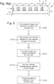
- Figure 2 shows steps of a first embodiment of a method by which the image array 10 can be formed.
- Figures 3(a) to (e) depict the corresponding process stages for an exemplary array.
- a release substance 18 is applied to a first surface of a first substrate 19 (optionally after treating the substrate 19 to enhance ink adhesion, e.g. with a primer layer or by corona treatment), which in this example is a transparent substrate (e.g. PET) although this is not essential as explained below.
- the release substance 18 is selectively applied according to a pattern such that the release substance is present in regions P 2 of the pattern and absent in between, defining elements P 1 .
- the pattern according to which the release substance 18 is applied ultimately defines the size, shape and position of the image elements in the image array and so, preferably, an application technique capable of high resolution is utilised.
- the elements P 1 and or the regions P 2 of the pattern are 50 microns or less in at least one dimension, preferably 30 microns or less, most preferably 20 microns or less. This at least one dimension may correspond to the line width of an elongate element, the (narrowest) side-to-side dimension of a circular or polygonal element, or the line weight of a microimage such as a letter or number, for example.
- Printing methods are preferred, such as intaglio, gravure, wet lithographic printing or dry lithographic printing, with which it is possible to achieve line widths down to around 30 microns.
- flexographic or letterpress type printing techniques are preferred, such as those disclosed in British patent application number 1317195.4 .
- Preferred coat weights for the release substance are therefore in the range 0.5 grams per square metre (gsm) to 2 gsm, most preferably around 1 gsm.
- a wetting agent such as ethanol may be added to the release substance to promote formation of the desired pattern regions.
- a first image I 1 is printed over the patterned release substance 18, as shown in Figure 3(b) .
- Any printing technique can be used to apply the first image and high resolution is not a requirement (though still desirable).
- the first image could be applied by a digital printing method such as laser printing or inkjet, or by techniques including lithographic printing, gravure printing, letterpress printing or flexographic printing.
- the first image may be formed of one or more inks, an "ink” being a substance comprising a binder (typically polymeric) carrying a visible colourant such as a dye, pigment or reflective (e.g. metallic or optically variable) particles.
- the first image may be a multi-coloured image, i.e.
- the first image could be a full colour image such as a RGB or CMYK image and may be highly complex, e.g. a photographic image such as a portrait.
- the first image I 1 may therefore be laid down in more than one print working using conventional multi-pass printing techniques. The different workings need only be registered to one another to the extent necessary to form a multi-coloured image which is acceptable to the human eye and need not take into account the need for accurately registered image elements, formed later.
- the array area is processed so as to remove the patterned release substance 18 from the substrate 19, which will also lift off those portions of the first image I 1 overlying the release substance regions.
- the result is an image array 10 as shown in Figure 3(c) . Only those portions of the first image I 1 located in the pattern elements P 1 remain, as first image elements 12. Between the first image elements 12 are regions 14, which here are transparent gaps.
- the manner in which the area is processed in step S120 to remove the release substance will depend on the nature of the release substance selected.
- the release substance comprises a soluble material, most preferably water soluble, and the processing involves washing the array area with an appropriate solvent such as water.
- the release substance 18 should preferably be highly soluble whilst also preferably having the ability to film-form into a dry, tack-free layer suitable for printing on. (It is not essential for the release substance 18 to be tack free since the first image could be printed directly over the release substance in the next step of an in-line process without any intermediate storage step which might otherwise involve winding the substrate web up on a reel).
- the efficiency of removal may be enhanced by also heating the solvent and/or applying mechanical removal means such as brushing or agitation.
- suitable soluble release substances include polyacrylic acid (PAA), polyvinyl alcohol (PVA), starch, carboxymethyl cellulose, polyethylene oxide, polyvinyl pyrolidinone, gelatine, pectin, guar gum, or gum Arabic.
- the release substance could comprise an oil (e.g. a low molecular weight oil) or a wax. Materials such as these may prevent or reduce retention of the overlying layer(s) onto the substrate, e.g. by degassing upon subsequent printing, or changing the surface energy of the substrate so as to promote reticulation and prevent proper adhesion of the print.
- the processing step S120 may be substantially passive, requiring little further intervention to remove the release material from the regions 14, e.g. simply wiping any loose material away.
- such an oil or wax based release substance may be activated by heating.
- the ink(s) from which the first image is formed should of course not be significantly dissolvable by the same solvent as that in which the release substance dissolves.
- the release substance 18 is water-soluble
- water-soluble inks such as common ink jet inks
- inks based on other solvents and also radiation-curable inks may still be used.
- the release substance 18 may include a filler, such as pigments. This roughens the surface of the release substrate and assists in preventing layers deposited on top (such as first image I 1 ) from forming a contiguous film, which may hinder removal of the release substrate.
- Suitable fillers include aerosols or chalk-like pigments. Removal of the release substance may also be promoted by forming the first image as a half-toned or screened print such that it includes discontinuities. It is also desirable that the ink forming the first image layer should break cleanly along the boundaries between elements P 1 and regions P 2 of the pattern, and this can be assisted by selecting an ink with a high filler (e.g. pigment) loading. Lithographic inks are particularly preferred for this purpose. Whilst the first image should be allowed to dry to an extent before step S120 is performed, it may be desirable not to allow complete drying so to avoid the first image layer forming a contiguous film.
- a particularly preferred option for printing the first image I 1 is to use radiation-curable (e.g. UV-curable) ink(s).
- the one or more inks will be printed in accordance with the first image and then step S120 will be performed to remove the regions overlying release substance 18.
- step S120 will be performed to remove the regions overlying release substance 18.
- the remaining portions of the first image are cured by exposure to appropriate radiation (UV) to fix the image elements.
- UV appropriate radiation
- the first image I 1 will appear to "flash" on and off as the device is tilted, as described in relation to Figure 1(c) .
- a second image I 2 which is continuous across the array area, may be provided in an optional step S130. This may be implemented in various different ways. In a preferred approach, the second image I 2 is applied (e.g. printed) onto the second surface of the first substrate, as shown in Figure 3(d) (note that this step could equally be performed before step S100 or at any point thereafter).
- the second image I 2 is exposed in the regions 14 between the first image elements 12, such that both images are visible from the same side of the arrangement (the upper side as depicted in the Figures).
- a focusing element array 5 is provided on top of the image array 10 (step S140, Figure 3(e) )
- the device will appear to switch between the first and second images as the assembly is tilted.
- the focussing element array 5 can be applied for example by laminating the image array 10 to a transparent layer 2 carrying the lenses.
- the transparent layer 2 is itself a transparent adhesive layer.
- the second image I 2 can likewise be formed by any convenient technique such as printing, and does not require especially high resolution. Importantly, no registration between the first and second images is required. Again, it is preferred that the second image I 2 is multi-coloured and it may be formed in multiple print workings. The security device will therefore display two different multi-coloured images as the device is tilted. The assortment of colours included in each of the two images is also preferably different in order to increase the visual contrast between the two images upon tilting.
- steps S130 and S140 may be reversed as denoted by the different arrows shown in Figure 2 .
- the image array 10 depicted in Figure 3(c) (carrying only the first image I 1 ) may be provided with a focusing element array 5 directly, forming a security device of the sort shown in Figure 1 .
- Figure 4 shows two alternative constructions of security device which may be formed using the above-described method.
- the first substrate 19 is itself used to space the focusing element array from the image array, i.e. acting as substrate 2 shown in Figure 1 ).
- the second image I 2 is then printed directly over the first image elements 12 on the same surface of substrate 19.
- the second image effectively fills in the regions 14 between the first image elements 12, so as to form second image element.
- a focusing element array 5 is applied to the second surface of the substrate 19 and both sets of image elements are viewed through the substrate 19 in use.
- the Figure 4(b) example is substantially the same except that rather than print the second image I 2 over the first image elements 12, it is formed on a second substrate 20 and then laminated over the first image elements (using a transparent adhesive, not shown). Again, the second image I 2 is exposed in the regions 14 between the first image elements 12.
- the Figure 4 examples are more preferable than those of Figure 3 since in Figure 3 the two image arrays are separated by the substrate 19 and hence are not at the same position with respect to the lenses unlike Figure 4 where effectively they are in the same plane.
- the thickness of the substrate 19 may be as low as 6 microns but this will have some effect on the device, albeit acceptable in some devices.
- the focusing element array 5 can be provided before or after the second image is applied.
- the first image I 1 should be applied with a high optical density, most preferably being substantially opaque, in order that when a second image I 2 is provided underneath it does not affect the appearance of the first image elements. If the first image elements were significantly light-transmissive, the second image would be visible to an extent through the first image elements which would diminish the resulting visual effect. In practice, it can be difficult to achieve sufficiently high print density and this also places limits on the ink compositions and printing techniques that can be used to form the first image I 1 .
- a second embodiment of a method of manufacturing an image array which addresses this issue is shown in Figure 5 , with corresponding manufacturing stages for an exemplary device being shown in Figures 6(a) to (f) .
- a release substance 18 is applied to a first substrate in accordance with a pattern, as shown in Figure 6(a) .
- a masking layer 17 is applied continuously across the array area, over the release substance 18.
- the masking layer is preferably substantially opaque to visible light, and most preferably is a metal or metal alloy layer, such as aluminium, copper, bronze, chromium or nickel, although any other high optical density material could be used such as a binder containing substantially opaque particles, e.g. aluminium oxide or titanium dioxide.
- a first image I 1 is then printed over the masking layer 17 (step 110), using any convenient printing technique as described previously. Again, most preferably the first image is multi-coloured.
- step S120 is performed whereby the array area is processed to remove the release substance 18. Since the masking layer 17 overlies the release substance 18, this also results in removal of the masking layer 17 (and the first image) from the regions 14 of the substrate to which the release substance had been applied. Again the nature of the removal process will depend on the type of release substance 18 used, as described above.
- the resulting image array 10 is shown in Figure 6(d) and it will be seen that portions of the masking layer 17 are retained only directly under the first image elements 12.
- the so-produced image array 10 can then be further processed in any of the ways already described in relation to the first embodiment.
- a second image I 2 may be provided (step S130), either by direct application to the other side of substrate 19 as shown in Figure 6(e) or by applying the image array to another surface.
- the masking layer portions 17 are located between the first and second images such that, even if the first image elements 12 have low optical density, the underlying second image I 2 is substantially obscured (and preferably entirely hidden) by the masking layer locally. As such the appearance of the first image elements 12 is not affected by the underlying second image I 2 .
- the masking layer is preferably of uniform appearance and most preferably reflects substantially white light.
- a metal or metal alloy layer such as aluminium or nickel is particularly preferred for this purpose and also provides the additional advantage of high reflectivity so as to enhance the visibility of the first image.
- the image array 10 can be combined with a focussing element array 5 (step S140) to form a security device 1 as shown in Figure 6(f) . As before this can be performed before or after the second image is provided.
- difficulties can be encountered in removing the release substance in step S120.
- the masking layer 17 is a metal or metal alloy layer, this can act as a barrier to the ingress of solvent fluid during washing and impede it from reaching the release substance 18. It has been found that such difficulties can be alleviated by providing the release substance with fillers such as pigments which result in a roughened surface and act to prevent the masking material forming a contiguous film over the release substance in regions 14. This enables fluid to permeate more successfully through the masking layer and thereby assists in the removal step.
- FIG. 7 An alternative method according to a third embodiment which avoids this difficulty is shown in Figure 7 , with corresponding manufacturing stages being depicted for an exemplary image array in Figures 8(a) to (g) .
- the masking layer 17 is applied to the substrate 19 first (step S106), continuously across the array area as shown in Figure 8(a) .
- step S100 is performed to apply release substance 18 onto the masking layer 17 in accordance with a desired pattern of elements P 1 and regions P 2 , as shown in Figure 8(b) .
- the first image I 1 is then printed over the patterned release substance 18 (step S110) using any technique as discussed previously.
- the removal step S120 now comprises two stages.
- step S122 the release substance 18 is removed together with the overlying portions on image I 1 in the same manner as previously described, the particulars of which will depend on the type of release substance in use.
- the resulting structure is shown in Figure 8(d) and it will be seen that the masking layer 17 is now exposed in the regions 14 between the first image elements 12.
- step S124 the exposed portions of the masking layer 17 are removed using the first image elements 14 to protect the unexposed portions of the masking layer 17.
- the exposed portions may be removed by etching with the first image elements 15 acting as an etch resist.
- the resulting image array 10 is shown in Figure 8(e) which it will be seen is the same as in Figure 6(d) .
- a second image I 2 and focussing element array 5 can then be provided as before.
- the method according to the third embodiment has the advantage that the release substance 18 is not covered by the masking layer 17 and therefore ingress of solvent is not impeded.
- the ink forming the first image does require suitable protective properties, e.g. to act as a resist against etchant.
- Lithographic inks and toners used in laser printing have been found suitable in this regard, amongst other examples.
- the use of a radiation-curable ink (as mentioned earlier) is particularly preferred in this embodiment since the ink can be made highly resistant to etchant upon curing.
- the first image elements 12 have been formed on a transparent first substrate 19 with any second image being provided either on the other surface of the substrate or over the top of the first image elements.
- the second image may be provided before the first image elements are formed.
- the first step is now to print the second image I 2 onto the first surface of the substrate 19 continuously across the array area (step S130). This can be performed using any desired technique as previously explained and high resolution is not essential.
- the resulting structure is shown in Figure 10(a) .
- Step S100 is then performed on top of the second image I 2 , with the patterned release substance 18 being applied to the surface of the second image as shown in Figure 10(b) .
- the next steps are then the same as in the first embodiment: a first image I 1 is printed over the release substance 18 (step 110), as shown in Figure 10(c) and then the release substance 18 and overlying portions of the first image are removed (step 120) using a technique appropriate to the selected release substance.
- the resulting image array 10 is shown in Figure 10(d) and it will be seen that the second image I 2 is exposed in the regions 14 between first image elements 12, effectively forming second image elements.
- a focusing element array 5 can then be provided over the image array 10 as before to form a security device 1 as shown in Figure 10(e) (step S140).
- the substrate 19 need not be transparent but could be translucent or even opaque.
- the necessarily high-resolution pattern elements 12 are achieved through high-resolution selective application of the release substance 18, typically by carefully controlled print processes. Since it is the pattern carried by the release substance which defines the ultimate size, shape and location of the image elements 12 (and the intervening regions 14), there are no significant constraints on the process by which the images themselves can be printed, thereby enabling the use of multi-coloured images which typically require multiple workings, between which only relatively low registration is generally achievable. Nonetheless it is still necessary to achieve very high resolution in the application of the release substance 18 itself, which carries with it the same attendant difficulties which are present in conventional single-colour fine line print processes.
- a fifth embodiment is depicted in Figures 12 and 13 which addresses this difficulty by providing an alternative way to form the patterned release substance layer 18.
- This can be used to implement step S100 in any of the embodiments described above, but will be described in the context of the first embodiment only for the sake of brevity.
- a photo-responsive release substance 18 is applied continuously across the array area on first substrate 19 (or onto a second image if this has already been formed as discussed above), resulting in the arrangement shown in Figure 13(a) .
- the release substance 18 may comprise any of the materials mentioned above in this connection, e.g. water soluble with the addition of a substance which is responsive to one or more wavelengths of radiation, e.g. UV.
- the substance causes the release substance 18 to become non-operational (i.e. will no longer act as a release substance, e.g. is no longer water soluble) in those areas in which it has been exposed to the radiation.
- the substance may respond to radiation by forming cross-links.
- the release substance 18 comprises a water-soluble, UV-crosslinking material.
- the release substance could comprise polyacrylic acid to which potassium dichromate has been added.
- the release substance 18 is then exposed to radiation of the appropriate wavelength (e.g. UV) in accordance with the desired pattern of elements P 1 in which the radiation is incident on the release substance and regions P 2 in which it is not.
- radiation of the appropriate wavelength e.g. UV
- This can be achieved for example by exposing the layer to an appropriate radiation source via a patterned mask, or by utilising a radiation beam such as a laser and directing it across the layer 18 in accordance with the pattern.
- a radiation beam such as a laser
- a first image I 1 is printed over the release layer 18 using any convenient technique (step S110, Figure 13(c) ).
- the array area is then processed in step S120 to remove the regions 18a of the release layer which remain operational, resulting in the image array 10 shown in Figure 13(d) .
- Each first image element 12 has underlying the first image I 1 a non-operational portion 18b of the release substance 18, spaced by empty regions 14.
- a second image I 2 can then be provided using any of the techniques previously described (step S130, Figure 13(e) ), and a focusing element array 5 can be overlaid to form a security device 1 as shown in Figure 13(f) .
- the second image I 2 may in practice be provided on the first surface of the substrate 19 before steps S102, S104 etc are performed on top.
- the resulting security device structure is shown in Figure 14(a) , the non-operational release substance portions 18b being located immediately between the two images.
- the release substance 18 could be of a type which only becomes operative upon irradiation at a suitable wavelength.
- US-A-4217407 discloses an ortho quinone diazide which is suitable for this purpose, one available form of which is V215 by Varichem.
- the material Upon exposure to appropriate radiation, the material becomes soluble in alkali whereas, where it has been masked, it will resist dissolution.
- the appropriate wavelength e.g. UV
- the retained non-operational release substance 18b may be of sufficiently high optical density to perform the function of the masking layer 17 described in previous embodiments.
- a non-transparent pigment could be added to the release substance to enhance this.
- a separate masking layer 17 may still be desirable and this can be achieved using either the method of the second embodiment or that of the third embodiment with steps S102 and S104 used to implement step 100.
- the security device structure resulting from the method of the second embodiment modified in this way is shown in Figure 14(b) , each first image element 12 having a masking layer portion 17 and a non-operative release layer portion 18b thereunder.
- the second image I 2 has been provided on the first surface of the substrate before the above-described steps have been performed.
- a correspondingly modified version of the third embodiment would result in the masking layer portions 17 lying under the non-operative release layer portions 18b, i.e. the order of these two layers will be reversed relative to that shown in Figure 14(b) .
- the two planes in which the first and second images lie respectively are as close to one another as possible, so that when the image array is combined with a focussing element array or other viewing component in order to form a security device, both images can be located close to the focal point of the array and/or little or no parallax between the two images is apparent.
- the two images are spaced from one another by 15 microns or less, preferably 10 microns or less, still preferably 5 microns or less.
- the substrate 19 is preferably 15 microns thick or less.
- Figure 15 shows a first exemplary manufacturing line suitable for implementing the method as a continuous web-based process (as is strongly preferred).
- a transparent substrate 19 is provided from a reel (not shown) as a continuous web.
- a release substance 18 is applied to one surface of the substrate 19 according to a desired pattern of regions, spaced by elements in which the release substance is absent.
- a first image I 1 is then printed over the patterned release substance 18 by a multi-colour print station 32, optionally in multiple passes.
- the substrate 19 then passes into a processing chamber 34 adapted to remove the release substance 18 and the portions of the first image I 1 thereon, e.g. by passing the substrate through a heated water bath and subsequent brushing. The result is a series of first image elements 12.
- the so-formed image array is then conveyed through a lens-forming station 36, which here comprises a cast-cure apparatus.
- a transparent curable resin 22 is applied to the second surface of the substrate 19 by an application roller 36a.
- a surface relief profile defining a lens array 5 is cast into the surface of the curable resin by an embossing roller 36b equipped with a corresponding profile in its surface.
- the resin 22 is cured, e.g. by irradiation or heat, so as to fix the lens structure.
- the result is a security device with a cross section corresponding to that shown in Figure 1(b) .
- FIGs 16(a) and (b) show an exemplary security document 50, here a paper-based banknote, provided with a security device 1 as formed by the process described with respect to Figure 15 .
- the banknote surface carries graphics such as star indicium 51, which have been printed on the banknote in a separate conventional process, e.g. by intaglio printing.
- the security device 1 is applied over a portion of the star shaped indicium 51, e.g. in the form of a foil or patch, affixed by way of a transparent adhesive.
- the resulting cross section through the document at a location across the security device 1 corresponds to that shown in Figure 4(b) , where the security document 50 forms substrate 20 and the second image I 2 is the star indicium 51 thereon.
- the security device 1 From a first viewing angle, as shown in Figure 16(a) , the security device 1 directs light from the first image elements 12 to the viewer with the result that a portion of the underlying star-shaped indicium 51 is concealed and instead the observer sees the first image I 1 . For simplicity this is depicted here as a uniform region but in practice a multi-coloured image is preferred as described above.
- the security device 1 directs light from the regions 14 between the first image elements 12 to the viewer, i.e. exhibiting second image I 2 which here is the underlying star graphic 51. Hence the full star shape is visible.
- Figure 17 shows another exemplary manufacturing apparatus.
- the process begins by printing the continuous second image I 2 onto the first substrate 19 (which may or may not be transparent) at a first print station 38, preferably in multiple colours.
- a patterned release substance 18 is then applied onto to the second image I 2 at station 30.
- a first image I 1 is then printed over the release pattern at a further print station 32, preferably in multiple colours.
- the substrate is then processed in chamber 34 to remove the release substance 18 and portions of the first image thereon, resulting in an image array corresponding to that in Figure 10(d) .
- the so-formed image array containing elements of both first and second images, can then be supplied as a security article such as a foil, thread, strip or patch.
- FIG 18 shows an exemplary security document 60, here a polymer banknote, into which the security article may be incorporated.
- the image array 10 is affixed to a transparent document substrate 61 in a window region defined by a gap in opacifying layers 62a, 62b provided on the document substrate.
- the image array 10 is arranged so that the elements of both the first and second images can be viewed through the document substrate 61, and joined by a transparent adhesive for example.
- a focusing element array 5 is provided to complete the security device.
- the focusing element array 5 and/or the image array 10 may be formed directly on the substrate or on respective additional layer(s) which are adhered to the substrate.
- the formation of the image array 10, focusing element array 5 and the polymer banknote 60 may each be performed in separate processes, optionally by separate entities, before being assembled to create the final security device.
- the device 1 may also be formed in a half-window region, for example in Figure 18 by extending the lower opacifying layer 62b across the device 1.
- the pattern of elements 12 and regions 14 can be configured to take any desirable form and this will be dictated by the type of security device in which the array is to be used.
- the elements 12 forming the pattern will be substantially identical to one another in terms of size and shape, and the pattern will be periodic at least in a first dimension.
- the image elements 12 will preferably be straight, parallel lines as shown for example in Figure 19(a) .
- the image array will be registered to the focusing element array in terms of orientation but not necessarily in terms of translational position along the periodic direction (i.e. x-axis, in this case).
- the ratio of surface area carrying first image elements 12 to that of the regions 14 therebetween will be around 1:1 so that about 50% of the available area is dedicated to each of the two images I 1 and I 2 (or to I 1 and a blank "image" if no second image is provided).
- the first image will be displayed at approximately half of the possible viewing angles and the second image will be displayed over the other half.
- the relative proportions of each image could be varied by adjusting the element width relative to the spacing between the elements.
- the proportion will lie in the range 40 to 60%, more preferably 45 to 55%.
- the periodicity of the pattern i.e. the pitch between one element 12 and the next
- the pitch of the image elements 12 is substantially the same as that as the focusing elements 5, in which case the footprint of one focusing element is represented by dashed outline 5a.
- the pitch of the focusing element array may be substantially equal to a multiple of that of the image array.
- the line 5b represents a focusing element with a pitch twice that of the image element pitch.
- Two-dimensional lenticular devices can also be formed, in which the optically variable effect is displayed as the device is tilted in either of two directions, preferably orthogonal directions.
- Examples of patterns suitable for forming image arrays for such devices are shown in Figures 19(b) to (d) .
- the image elements 12 are formed as grid patterns of "dots", with periodicity in more than one dimension.
- the first image elements 12 are square and arranged on an orthogonal grid to form a "checkerboard" pattern with resulting regions 14 in which the first image is absent.
- the focusing elements in this case will be spherical or aspherical, and arranged on a corresponding orthogonal grid, registered to the image array in terms of orientation but not necessarily in terms of translational position along the x or y-axes. If the pitch of the focussing elements is the same as that of the image array in both the x and y directions, the footprint of one focussing element will be represented by the dashed line 5a. From an off-axis starting position, as the device is tilted left-right, the displayed image will switch as the different elements or regions are directed to the viewer, and likewise the same switch will be exhibited as the device is tilted up-down. If the pitch of the focusing elements is twice that of the image array, the image will switch multiple times as the device is tilted in any one direction. Again the proportion of image elements 12 to regions 14 is approximately 50%.
- the pattern is substantially the same as that of Figure 19(b) , but here the patterns elements 12 are circular rather than square. Any other "dot" shape could alternatively be used, e.g. polygonal.
- the regions 14 between the elements 12 join one another due to the increased spacing of the elements 12 with the result that here the proportion of the array corresponding to the first image is less than 50%.
- the elements 12 are once again circular but are arranged on a close-packed hexagonal grid. This may be appropriate for example where the focusing element array is also arranged on a hexagonal grid. Again any other "dot" shape may be adopted and in this case hexagonal regions may be preferred. Once again the proportion of the array corresponding to the first image is less than 50%.
- first image or the second image, or both be multi-coloured, i.e. made up of at least two different colours and more preferably at least three.
- first image may contain at least one colour which is not included in the second image, so that there is a colour contrast upon switching between different images.
- Either or both images may be printed in multiple print workings and may be screened or half-toned.
- Figure 20 is a photograph showing a portion of an exemplary image array 10 made in accordance with the above-described techniques, at a much enlarged scale.
- the pattern is a line pattern as described in relation to Figure 19(a) .
- the first image has been formed as a multi-coloured halftone print such that multiple colours are exhibited by each of the first image elements 12.
- the regions 14 between the line elements 12 are transparent but if the structure is placed over a second image, portions of that second image would be visible therethrough.
- the width w of each image element 12 is 150 microns
- the pattern pitch is 300 microns (this sample was produced with a relatively coarse resolution for test purposes).
- Figure 21 is a photograph showing a portion of another exemplary image array 10 made in accordance with the above-described techniques, again at a much enlarged scale.
- the pattern is a line pattern of first image elements 12 and transparent intervening regions 14.
- the first image is multi-coloured, here consisting of two colours, which give rise to the variation in colour seen along certain of the first image elements 12 and also between different ones of the first image elements 12.
- image element 12' is wholly displayed in a first colour, which here appears light, while another image element 12" is wholly of a second colour, which here appears relatively dark.
- Other image elements such as 12* include portions of the first colour, e.g. portion 12a, as well as portions of the second colour, e.g. portion 12b.
- the arrangement of the various colours will depend on the content of the first image.
- the first image elements 12 have a width w of approximately 30 microns and the spacing s between them is around 50 microns, the pattern pitch being around 80 microns.
- the proportion of the image array 10 corresponding to the first image is therefore around 38%.
- each image element 12 will now define a microimage, i.e. a complete miniature representation of the image to be viewed, rather than a portion thereof.
- each microimage could comprise one or more letters, numbers, logos or other symbols, all of the microimages in the array being substantially identical.
- the image elements 12 can correspond to the microimages themselves or the background surrounding them (i.e. the microimages can be positive or negative).
- the microimages will primarily be defined by the shape and size of the pattern elements as laid down by the release substance, rather than by the first (or second) image, which now only acts to colour the microimages.
- Figure 22 shows an exemplary image array suitable for use in a moire magnifier device.
- Each first image element 12 is a star shaped symbol, and the elements are arranged on a regular orthogonal grid, spaced from one another by region 14 which acts as a background.
- Each star 12 may have a diameter of around 20 microns for example.
- a corresponding focussing element array is illustrated by dashed-line circles 5, each of which represents a spherical or aspherical lens.
- the lens array is also arranged on an orthogonal grid of similar pitch to that of the microimage array. However, the two arrays are slightly mismatched in terms of pitch and/or orientation, in order to give rise to the moire magnification effect. Registration between the two arrays is not required. The observer viewing the security device will see a magnified version of the array of stars.
- Figure 23 shows an exemplary image array suitable for use in an integral imaging device.
- each first image element 12 defines the outline of a cube, each microimage depicting the cube from a different viewpoint, and again arranged on an orthogonal grid.
- the line width of each microimage may be around 5 microns for example.
- the region 14 provides the background to the microimages (both inside and outside the cube outlines).
- a corresponding focussing array 5 is provided, this time of matching pitch and orientation to the microimage array, and preferably registered to the image array at least in terms of orientation. When the security device is viewed, a three-dimensional image of the cube will be exhibited.
- the first and second images may be single-colour images, i.e. blocks of uniform colour. If the first and second images are multi-coloured, the synthetic magnification mechanism may lead to visual combining of several colours resulting in the magnified image taking on some in-between colour which may or may not be desirable.
- Security devices of the sorts described above can be incorporated into or applied to any product for which an authenticity check is desirable.
- such devices may be applied to or incorporated into documents of value such as banknotes, passports, driving licences, cheques, identification cards etc.
- the image array and/or the complete security device can either be formed directly on the security document or may be supplied as part of a security article, such as a security thread or patch, which can then be applied to or incorporated into such a document.
- Such security articles can be arranged either wholly on the surface of the base substrate of the security document, as in the case of a stripe or patch, or can be visible only partly on the surface of the document substrate, e.g. in the form of a windowed security thread.
- Security threads are now present in many of the world's currencies as well as vouchers, passports, travellers' cheques and other documents. In many cases the thread is provided in a partially embedded or windowed fashion where the thread appears to weave in and out of the paper and is visible in windows in one or both surfaces of the base substrate.
- windowed threads can be found in EP-A-0059056 .
- EP-A-0860298 and WO-A-03095188 describe different approaches for the embedding of wider partially exposed threads into a paper substrate.
- Wide threads typically having a width of 2 to 6mm, are particularly useful as the additional exposed thread surface area allows for better use of optically variable devices, such as that presently disclosed.
- the security article may be incorporated into a paper or polymer base substrate so that it is viewable from both sides of the finished security substrate at at least one window of the document.
- Methods of incorporating security elements in such a manner are described in EP-A-1141480 and WO-A-03054297 .
- one side of the security element is wholly exposed at one surface of the substrate in which it is partially embedded, and partially exposed in windows at the other surface of the substrate.
- Base substrates suitable for making security substrates for security documents may be formed from any conventional materials, including paper and polymer. Techniques are known in the art for forming substantially transparent regions in each of these types of substrate.
- WO-A-8300659 describes a polymer banknote formed from a transparent substrate comprising an opacifying coating on both sides of the substrate. The opacifying coating is omitted in localised regions on both sides of the substrate to form a transparent region.
- the transparent substrate can be an integral part of the security device or a separate security device can be applied to the transparent substrate of the document.
- WO-A-0039391 describes a method of making a transparent region in a paper substrate. Other methods for forming transparent regions in paper substrates are described in EP-A-723501 , EP-A-724519 , WO-A-03054297 and EP-A-1398174 .
- the security device may also be applied to one side of a paper substrate, optionally so that portions are located in an aperture formed in the paper substrate.
- An example of a method of producing such an aperture can be found in WO-A-03054297 .
- An alternative method of incorporating a security element which is visible in apertures in one side of a paper substrate and wholly exposed on the other side of the paper substrate can be found in WO-A-2000/39391 .
- Figure 24 depicts an exemplary document of value 70, here in the form of a banknote.
- Figure 24a shows the banknote in plan view whilst Figure 24b shows a cross-section of the same banknote along the lines X-X' and Figure 24c shows a cross-section through a variation of the banknote.
- the banknote is a polymer (or hybrid polymer/paper) banknote, having a transparent substrate 72.
- Two opacifying layers 73 and 74 are applied to either side of the transparent substrate 72, which may take the form of opacifying coatings such as white ink, or could be paper layers laminated to the substrate 72.
- the opacifying layers 73 and 74 are omitted across selected regions 71 (and 71'), each of which forms a window within which a security device 1, 1' is located.
- a security device 1 is disposed within window 71, with a focusing element array 5 arranged on one surface of the transparent substrate 72, and image array 10 on the other (e.g. as in Figure 18 above).
- Figure 24(c) shows a variation in which a second security device 10' is also provided on banknote 70, in a second window 71'. The arrangement of the second security device 1' can be reversed so that its optically variable effect is viewable from the opposite side of the security document as that of device 1, if desired.
- any or all of the windows 71, 71' could instead be "half-windows", in which an opacifying layer (e.g. 73 or 74) is continued over all or part of the image array 10.
- an opacifying layer e.g. 73 or 74
- the half-window region will tend to appear translucent relative to surrounding areas in which opacifying layers 73 and 74 are provided on both sides.
- the banknote 80 is a conventional paper-based banknote provided with a security article 85 in the form of a security thread, which is inserted during paper-making such that it is partially embedded into the paper so that portions of the paper 82 and 83 lie on either side of the thread.
- a security article 85 in the form of a security thread, which is inserted during paper-making such that it is partially embedded into the paper so that portions of the paper 82 and 83 lie on either side of the thread.
- the window regions 81 may for example be formed by abrading the surface of the paper in these regions after insertion of the thread. It should be noted that it is not necessary for the window regions 81 to be "full thickness" windows: the thread 85 need only be exposed on one surface if preferred.
- the security device is formed on the thread 85, which comprises a transparent substrate a focusing array 5 provided on one side and an image array 10 provided on the other.
- Windows 81 reveal parts of the device 1, which may be formed continuously along the thread.
- the lens arrays are depicted as being discontinuous between each exposed region of the thread, although in practice typically this will not be the case and the lens arrays (and image arrays) will be formed continuously along the thread.
- several security devices could be spaced from each other along the thread, as in the embodiment depicted, with different or identical images displayed by each).
- the banknote 90 is again a conventional paper-based banknote, provided with a strip element or insert 95.
- the strip 95 is based on a transparent substrate and is inserted between two plies of paper 92 and 93.
- the security device 1 is formed by a lens array 5 on one side of the strip substrate 95, and an image arrays 10 on the other.
- the paper plies 92 and 93 are apertured across region 91 to reveal the security device 1, which in this case may be present across the whole of the strip 95 or could be localised within the aperture region 95. It should be noted that the ply 93 need not be apertured and could be continuous across the security device.
- Security article 105 is a strip or band comprising a security device 1 according to any of the embodiments described above.
- the security article 105 is formed into a security document 100 comprising a fibrous substrate, using a method described in EP-A-1141480 .
- the strip is incorporated into the security document such that it is fully exposed on one side of the document ( Figure 27(a) ) and exposed in one or more windows 101 on the opposite side of the document ( Figure 27(b) ).
- the security device 1 is formed on the strip 105, which comprises a transparent substrate with a lens array 5 formed on one surface and a co-operating image array 10 as previously described on the other
- a similar construction can be achieved by providing paper 100 with an aperture 101 and adhering the strip element 105 onto one side of the paper 100 across the aperture 101.
- the aperture may be formed during papermaking or after papermaking for example by die-cutting or laser cutting.
- a complete security device 1 could be formed entirely on one surface of a security document which could be transparent, translucent or opaque, e.g. a paper banknote irrespective of any window region.
- the image array 10 can be affixed to the surface of the substrate, e.g. by adhesive or hot or cold stamping, either together with a corresponding focusing element array 5 or in a separate procedure with the focusing array 5 being applied subsequently.
- the adhesive could be applied to the lens array(s) as a pattern that leaves an intended windowed zone of the lens array(s) uncoated, with the strip or patch then being applied in register (in the machine direction of the substrate) so the uncoated lens region registers with the substrate hole or window.
- the security device of the current invention can be made machine readable by the introduction of detectable materials in any of the layers or by the introduction of separate machine-readable layers.
- Detectable materials that react to an external stimulus include but are not limited to fluorescent, phosphorescent, infrared absorbing, thermochromic, photochromic, magnetic, electrochromic, conductive and piezochromic materials.
- Additional optically variable devices or materials can be included in the security device such as thin film interference elements, liquid crystal material and photonic crystal materials. Such materials may be in the form of filmic layers or as pigmented materials suitable for application by printing. If these materials are transparent they may be included in the same region of the device as the security feature of the current invention or alternatively and if they are opaque may be positioned in a separate laterally spaced region of the device.
- the security device may comprise a metallic layer laterally spaced from the security feature of the current invention.
- the presence of a metallic layer can be used to conceal the presence of a machine readable dark magnetic layer.
- Suitable magnetic materials include iron oxide pigments (Fe 2 O 3 or Fe 3 O 4 ), barium or strontium ferrites, iron, nickel, cobalt and alloys of these.
- alloys include materials such as Nickel:Cobalt, Iron:Aluminium:Nickel:Cobalt and the like.
- Flake Nickel materials can be used; in addition Iron flake materials are suitable. Typical nickel flakes have lateral dimensions in the range 5-50 microns and a thickness less than 2 microns. Typical iron flakes have lateral dimensions in the range 10-30 microns and a thickness less than 2 microns.
- a transparent magnetic layer can be incorporated at any position within the device structure.
- Suitable transparent magnetic layers containing a distribution of particles of a magnetic material of a size and distributed in a concentration at which the magnetic layer remains transparent are described in WO03091953 and WO03091952 .
- Negative or positive indicia may be created in the metallic layer or any suitable opaque layer.
- the masking layer 17 could itself be a magnetic material.
- One way to produce partially metallised/demetallised films in which no metal is present in controlled and clearly defined areas, is to selectively demetallise regions using a resist and etch technique such as is described in US-B-4652015 .
- Other techniques for achieving similar effects are for example aluminium can be vacuum deposited through a mask, or aluminium can be selectively removed from a composite strip of a plastic carrier and aluminium using an excimer laser.
- the metallic regions may be alternatively provided by printing a metal effect ink having a metallic appearance such as Metalstar® inks sold by Eckart.
Landscapes
- Engineering & Computer Science (AREA)
- Manufacturing & Machinery (AREA)
- Mechanical Engineering (AREA)
- Credit Cards Or The Like (AREA)
- Business, Economics & Management (AREA)
- Accounting & Taxation (AREA)
- Finance (AREA)
- Printing Methods (AREA)
Claims (18)
- Verfahren zum Herstellen einer Anordnung von Bildelementen (12) für eine Sicherheitsvorrichtung, umfassend:(a) Auftragen eines Trennstoffs (18) über einen Anordnungsbereich auf einem ersten Substrat hinweg gemäß einem Muster, das Regionen (P2) umfasst, in denen der Trennstoff wirksam ist und die durch Elemente (P1) beabstandet sind, in denen der Trennstoff fehlt oder unwirksam ist; dann(b) Drucken eines ersten Bilds (I1) durchgehend über den Anordnungsbereich hinweg über dem gemusterten Trennstoff; und dann(c) Verarbeiten des Anordnungsbereichs, um den Trennstoff und die Abschnitte des ersten Bilds darauf in den Regionen des Musters zu entfernen, wobei Elemente des ersten Bilds gemäß dem Muster beibehalten werden, um die Anordnung von ersten Bildelemente zu bilden;
wobei das Muster in mindestens einer ersten Dimension periodisch ist und die von dem Muster definierten Elemente im Wesentlichen zueinander identisch sind. - Verfahren nach Anspruch 1, wobei Schritt (a) weiter das Auftragen einer Abdeckschicht durchgehend über den Anordnungsbereich hinweg umfasst, bevor oder nachdem der Trennstoff aufgetragen wird, und Schritt (c) weiter das Entfernen der Abdeckschicht in den Regionen des Musters umfasst, sodass die Abdeckschicht nur unter den ersten Bildelementen beibehalten wird.
- Verfahren nach Anspruch 2, wobei Schritt (a) Folgendes umfasst:(a1) Auftragen des Trennstoffs gemäß dem Muster; und dann(a2) Auftragen der Abdeckschicht durchgehend über dem Trennstoff über den Anordnungsbereich hinweg;
und wobei in Schritt (c) die Abdeckschicht durch das Entfernen des Trennstoffs darunter in den Regionen des Musters entfernt wird. - Verfahren nach Anspruch 2, wobei Schritt (a) Folgendes umfasst:(a1') Auftragen der Abdeckschicht durchgehend über den Anordnungsbereich hinweg; und dann(a2') Auftragen des Trennstoffs gemäß dem Muster über der Abdeckschicht;und Schritt (c) Folgendes umfasst:(c1) Verarbeiten des Anordnungsbereichs, um den Trennstoff und die Abschnitte des ersten Bilds darauf in den Regionen des Musters zu entfernen; und dann(c2) Verwenden der beibehaltenen ersten Bildelemente als Abdeckmittel, Verarbeiten des Anordnungsbereichs, um die Abdeckschicht in den Regionen zwischen den ersten Bildelementen zu entfernen.
- Verfahren nach einem der vorangehenden Ansprüche, wobei in Schritt (a) der Trennstoff selektiv nur auf die Regionen der Muster aufgetragen wird, vorzugsweise mittels Drucken.
- Verfahren nach einem der Ansprüche 1 bis 4, wobei in Schritt (a) der Trennstoff durchgehend über den Anordnungsbereich hinweg aufgetragen wird und dann gemäß dem Muster mit Strahlung einer Wellenlänge beaufschlagt wird, auf die der Trennstoff reagiert, wobei die Strahlung den Trennstoff in den Musterelementen unwirksam macht, wobei vorzugsweise der Trennstoff durch eine gemusterte Abdeckung hindurch oder mittels eines gemäß dem Muster gerichteten Strahlungsstrahls mit der Strahlung beaufschlagt wird.
- Verfahren nach einem der vorangehenden Ansprüche, wobei das erste Bild mehrfarbig ist; und/oder das erste Bild gerastert oder ein Halbtonbild ist; und/oder in Schritt (b) das erste Bild in mehr als einem Druckarbeitsgang aufgetragen wird.
- Verfahren nach einem der vorangehenden Ansprüche, wobei es sich bei dem Muster um ein Linienmuster handelt, das in der ersten Dimension, die zu der Richtung der Linien senkrecht ist, periodisch ist, oder es sich bei dem Muster um ein Gittermuster handelt, das in der ersten Dimension und in einer zweiten Dimension periodisch ist.
- Verfahren nach einem der Ansprüche 1 bis 7, wobei jede Region oder jedes Element des Musters ein Mikrobild definiert, vorzugsweise ein/e/n oder mehrere Buchstaben, Zahlen, Logos oder andere Symbole, wobei die Mikrobilder im Wesentlichen zueinander identisch sind.
- Verfahren nach einem der vorangehenden Ansprüche, das weiter Folgendes umfasst:
(d) vor, während oder nach Schritten (a), (b) und (c), Bereitstellen eines zweiten Bilds durchgehend über den Anordnungsbereich hinweg über oder unter dem ersten Bild, sodass Elemente des zweiten Bilds durch die Regionen zwischen den beibehaltenen Elementen des ersten Bilds hindurch freigelegt sind, wodurch die Elemente beider Bilder von derselben Seite der Bildanordnung aus betrachtet werden können. - Verfahren nach Anspruch 10, wobei in Schritt (d) das zweite Bild auf einer ersten Oberfläche des Substrats bereitgestellt wird und Schritte (a), (b) und (c) anschließend zuoberst auf dem zweiten Bild auf der ersten Oberfläche des ersten Substrats ausgeführt werden; oder wobei Schritte (a), (b) und (c) auf einer ersten Oberfläche des ersten Substrats ausgeführt werden und in Schritt (d) das zweite Bild auf einer zweiten Oberfläche des ersten Substrats bereitgestellt wird, wobei das erste Substrat mindestens halbdurchsichtig ist; oder wobei in Schritt (d) das zweite Bild auf einem zweiten Substrat bereitgestellt wird, an dem das erste Substrat fixiert ist, wobei das erste und/oder das zweite Substrat mindestens halbdurchsichtig sind.
- Verfahren nach Anspruch 10 oder 11, wenn abhängig von einem der Ansprüche 2 bis 4, wobei sich die Abdeckschicht zwischen dem ersten und dem zweiten Bild befindet.
- Verfahren nach einem der Ansprüche 10 bis 12, wobei das zweite Bild mehrfarbig ist; und/oder das zweite Bild gerastert oder ein Halbtonbild ist; und/oder Schritt (d) das Drucken des zweiten Bilds, vorzugsweise in mehr als einem Druckarbeitsgang, umfasst.
- Verfahren zum Herstellen einer Bildanordnung für eine Sicherheitsvorrichtung, umfassend:(a) Auftragen eines Trennstoffs über einen Anordnungsbereich hinweg gemäß einem Muster, das Regionen umfasst, in denen der Trennstoff wirksam ist und die durch Elemente beabstandet sind, in denen der Trennstoff fehlt oder unwirksam ist; dann(b) Drucken eines ersten Bilds durchgehend über den Anordnungsbereich hinweg über dem gemusterten Trennstoff; dann(c) Verarbeiten des Anordnungsbereichs, um den Trennstoff und die Abschnitte des ersten Bilds darauf in den Regionen des Musters zu entfernen, wobei Elemente des ersten Bilds gemäß dem Muster beibehalten werden; und(d) vor, während oder nach Schritten (a), (b) und (c), Bereitstellen eines zweiten Bilds durchgehend über den Anordnungsbereich hinweg über oder unter dem ersten Bild, sodass Elemente des zweiten Bilds durch die Regionen zwischen den beibehaltenen Elementen des ersten Bilds hindurch freigelegt sind, was in einer Bildanordnung resultiert, wodurch die Elemente beider Bilder von derselben Seite der Bildanordnung aus betrachtet werden können; wobei Schritte (a), (b) und (c) auf einem Substrat ausgeführt werden, auf das das zweite Bild aufgetragen worden ist oder aufgetragen werden wird, oder welchem benachbart das zweite Bild angeordnet worden ist oder werden wird.
- Verfahren zum Herstellen einer Sicherheitsvorrichtung, umfassend:(i) Herstellen einer Bildanordnung unter Verwendung des Verfahrens nach einem der Ansprüche 1 bis 14; und(ii) Bereitstellen einer den Anordnungsbereich überlappenden Fokussierungselementanordnung; wobei die Bildanordnung und die Fokussierungselementanordnung konfiguriert sind, um zusammenzuwirken, um einen optisch veränderlichen Effekt zu erzeugen.
- Verfahren nach Anspruch 15, wobei die Fokussierungselementanordnung derart konfiguriert ist, dass jedes Fokussierungselement Licht von einem jeweiligen der ersten Bildelemente oder von einer jeweiligen der Regionen dazwischen in Abhängigkeit von dem Betrachtungswinkel lenken kann, wodurch, abhängig von dem Betrachtungswinkel, die Anordnung von Fokussierungselementen Licht von entweder der Anordnung erster Bildelemente oder von den Regionen dazwischen lenkt, sodass, wenn die Vorrichtung gekippt ist, das erste Bild von den ersten Bildelementen in Kombination unter einem ersten Bereich von Betrachtungswinkeln und nicht unter einem zweiten Bereich von Betrachtungswinkeln angezeigt wird, und wobei vorzugsweise Schritt (i) das Herstellen einer Bildanordnung unter Verwendung des Verfahrens nach einem der Ansprüche 10 bis 13 umfasst, wodurch die zweiten Bildelemente in den Regionen zwischen den ersten Bildelementen freigelegt sind, sodass, wenn die Vorrichtung gekippt ist, das erste Bild von den ersten Bildelementen in Kombination unter dem ersten Bereich von Betrachtungswinkeln angezeigt wird und das zweite Bild von den zweiten Bildelementen in Kombination unter dem zweiten Bereich von Betrachtungswinkeln angezeigt wird.
- Bildanordnung für eine Sicherheitsvorrichtung, die gemäß einem der Ansprüche 1 bis 14 hergestellt wird.
- Sicherheitsvorrichtung, die gemäß einem der Ansprüche 15 bis 16 hergestellt wird.
Applications Claiming Priority (2)
| Application Number | Priority Date | Filing Date | Title |
|---|---|---|---|
| GB1510072.0A GB2539389B (en) | 2015-06-10 | 2015-06-10 | Image arrays for security devices and methods of manufacture thereof |
| PCT/GB2016/051708 WO2016198875A1 (en) | 2015-06-10 | 2016-06-09 | Image arrays for security devices and methods of manufacture thereof |
Publications (2)
| Publication Number | Publication Date |
|---|---|
| EP3307552A1 EP3307552A1 (de) | 2018-04-18 |
| EP3307552B1 true EP3307552B1 (de) | 2019-03-27 |
Family
ID=53785242
Family Applications (1)
| Application Number | Title | Priority Date | Filing Date |
|---|---|---|---|
| EP16729338.0A Active EP3307552B1 (de) | 2015-06-10 | 2016-06-09 | Bildarrays für sicherheitsvorrichtungen und verfahren zur herstellung davon |
Country Status (3)
| Country | Link |
|---|---|
| EP (1) | EP3307552B1 (de) |
| GB (1) | GB2539389B (de) |
| WO (1) | WO2016198875A1 (de) |
Families Citing this family (4)
| Publication number | Priority date | Publication date | Assignee | Title |
|---|---|---|---|---|
| CN109475327B (zh) | 2016-03-08 | 2023-01-24 | 达斯特一致有限责任公司 | 根据取向信息生成唯一码 |
| GB2564076A (en) * | 2017-03-24 | 2019-01-09 | De La Rue Int Ltd | Security devices |
| CN114929490B (zh) * | 2019-11-05 | 2025-01-10 | 达斯特一致有限责任公司 | 施加和使用唯一的不可克隆物理标识符 |
| DE102020113144A1 (de) * | 2020-05-14 | 2021-11-18 | Leonhard Kurz Stiftung & Co. Kg | Verfahren zum Herstellen eines Mehrschichtkörpers sowie ein Mehrschichtkörper |
Family Cites Families (7)
| Publication number | Priority date | Publication date | Assignee | Title |
|---|---|---|---|---|
| EP0967091A1 (de) * | 1998-06-26 | 1999-12-29 | Alusuisse Technology & Management AG | Gegenstand mit optischem Effekt |
| DE102004031099B4 (de) * | 2004-06-28 | 2006-07-27 | Leonhard Kurz Gmbh & Co. Kg | Verfahren zur Herstellung einer bereichsweisen Metallisierung |
| WO2007048563A2 (de) * | 2005-10-27 | 2007-05-03 | Ovd Kinegram Ag | Verfahren zum transfer eines mehrschichtkörpers sowie transferfolie |
| EP1886834B1 (de) * | 2006-08-11 | 2013-10-16 | National Bank of Belgium | Drei-Bilder-Kombination |
| EP1886827B1 (de) * | 2006-08-11 | 2009-12-23 | National Bank of Belgium | Verstecktes Bild |
| DE102011050746A1 (de) * | 2011-05-31 | 2012-12-06 | Hologram Industries Research Gmbh | Mehrschichtkörper, Verfahren zu dessen Herstellung und Herstellung fälschungssicherer Dokumente unter dessen Verwendung |
| DE102012014294A1 (de) * | 2012-07-19 | 2014-01-23 | Giesecke & Devrient Gmbh | Verfahren zur Herstellung eines mehrschichtigen Sicherheitselements |
-
2015
- 2015-06-10 GB GB1510072.0A patent/GB2539389B/en not_active Expired - Fee Related
-
2016
- 2016-06-09 EP EP16729338.0A patent/EP3307552B1/de active Active
- 2016-06-09 WO PCT/GB2016/051708 patent/WO2016198875A1/en not_active Ceased
Also Published As
| Publication number | Publication date |
|---|---|
| GB201510072D0 (en) | 2015-07-22 |
| EP3307552A1 (de) | 2018-04-18 |
| GB2539389B (en) | 2017-12-06 |
| GB2539389A (en) | 2016-12-21 |
| WO2016198875A1 (en) | 2016-12-15 |
Similar Documents
| Publication | Publication Date | Title |
|---|---|---|
| US10981411B2 (en) | Security devices and methods of manufacture thereof | |
| EP3174730B1 (de) | Sicherheitsvorrichtungen und verfahren zur herstellung davon | |
| EP3024662B1 (de) | Sicherheitsvorrichtung und verfahren zur herstellung | |
| US9731539B2 (en) | Security devices | |
| US10300730B2 (en) | Methods of manufacturing image element arrays for security devices | |
| EP3448693B1 (de) | Verfahren zur herstellung von bildmustern für sicherheitsvorrichtungen | |
| WO2016198875A1 (en) | Image arrays for security devices and methods of manufacture thereof | |
| EP4284655B1 (de) | Sicherheitsvorrichtungen und verfahren zur herstellung davon | |
| GB2562592A (en) | Methods of manufacturing security devices and image arrays therefor | |
| EP3600902A1 (de) | Sicherheitsvorrichtungen | |
| WO2025125813A1 (en) | Security devices and methods of manufacture thereof |
Legal Events
| Date | Code | Title | Description |
|---|---|---|---|
| STAA | Information on the status of an ep patent application or granted ep patent |
Free format text: STATUS: THE INTERNATIONAL PUBLICATION HAS BEEN MADE |
|
| PUAI | Public reference made under article 153(3) epc to a published international application that has entered the european phase |
Free format text: ORIGINAL CODE: 0009012 |
|
| STAA | Information on the status of an ep patent application or granted ep patent |
Free format text: STATUS: REQUEST FOR EXAMINATION WAS MADE |
|
| 17P | Request for examination filed |
Effective date: 20171219 |
|
| AK | Designated contracting states |
Kind code of ref document: A1 Designated state(s): AL AT BE BG CH CY CZ DE DK EE ES FI FR GB GR HR HU IE IS IT LI LT LU LV MC MK MT NL NO PL PT RO RS SE SI SK SM TR |
|
| AX | Request for extension of the european patent |
Extension state: BA ME |
|
| DAV | Request for validation of the european patent (deleted) | ||
| DAX | Request for extension of the european patent (deleted) | ||
| GRAP | Despatch of communication of intention to grant a patent |
Free format text: ORIGINAL CODE: EPIDOSNIGR1 |
|
| STAA | Information on the status of an ep patent application or granted ep patent |
Free format text: STATUS: GRANT OF PATENT IS INTENDED |
|
| INTG | Intention to grant announced |
Effective date: 20181024 |
|
| GRAS | Grant fee paid |
Free format text: ORIGINAL CODE: EPIDOSNIGR3 |
|
| GRAA | (expected) grant |
Free format text: ORIGINAL CODE: 0009210 |
|
| STAA | Information on the status of an ep patent application or granted ep patent |
Free format text: STATUS: THE PATENT HAS BEEN GRANTED |
|
| RBV | Designated contracting states (corrected) |
Designated state(s): AL AT BE BG CH CY CZ DE DK EE ES FI FR GR HR HU IE IS IT LI LT LU LV MC MK MT NL NO PL PT RO RS SE SI SK SM TR |
|
| AK | Designated contracting states |
Kind code of ref document: B1 Designated state(s): AL AT BE BG CH CY CZ DE DK EE ES FI FR GR HR HU IE IS IT LI LT LU LV MC MK MT NL NO PL PT RO RS SE SI SK SM TR |
|
| REG | Reference to a national code |
Ref country code: CH Ref legal event code: EP |
|
| REG | Reference to a national code |
Ref country code: AT Ref legal event code: REF Ref document number: 1112596 Country of ref document: AT Kind code of ref document: T Effective date: 20190415 |
|
| REG | Reference to a national code |
Ref country code: IE Ref legal event code: FG4D |
|
| REG | Reference to a national code |
Ref country code: DE Ref legal event code: R096 Ref document number: 602016011621 Country of ref document: DE |
|
| REG | Reference to a national code |
Ref country code: CH Ref legal event code: NV Representative=s name: VALIPAT S.A. C/O BOVARD SA NEUCHATEL, CH |
|
| PG25 | Lapsed in a contracting state [announced via postgrant information from national office to epo] |
Ref country code: LT Free format text: LAPSE BECAUSE OF FAILURE TO SUBMIT A TRANSLATION OF THE DESCRIPTION OR TO PAY THE FEE WITHIN THE PRESCRIBED TIME-LIMIT Effective date: 20190327 Ref country code: FI Free format text: LAPSE BECAUSE OF FAILURE TO SUBMIT A TRANSLATION OF THE DESCRIPTION OR TO PAY THE FEE WITHIN THE PRESCRIBED TIME-LIMIT Effective date: 20190327 Ref country code: NO Free format text: LAPSE BECAUSE OF FAILURE TO SUBMIT A TRANSLATION OF THE DESCRIPTION OR TO PAY THE FEE WITHIN THE PRESCRIBED TIME-LIMIT Effective date: 20190627 Ref country code: SE Free format text: LAPSE BECAUSE OF FAILURE TO SUBMIT A TRANSLATION OF THE DESCRIPTION OR TO PAY THE FEE WITHIN THE PRESCRIBED TIME-LIMIT Effective date: 20190327 |
|
| REG | Reference to a national code |
Ref country code: NL Ref legal event code: MP Effective date: 20190327 |
|
| PG25 | Lapsed in a contracting state [announced via postgrant information from national office to epo] |
Ref country code: BG Free format text: LAPSE BECAUSE OF FAILURE TO SUBMIT A TRANSLATION OF THE DESCRIPTION OR TO PAY THE FEE WITHIN THE PRESCRIBED TIME-LIMIT Effective date: 20190627 Ref country code: NL Free format text: LAPSE BECAUSE OF FAILURE TO SUBMIT A TRANSLATION OF THE DESCRIPTION OR TO PAY THE FEE WITHIN THE PRESCRIBED TIME-LIMIT Effective date: 20190327 Ref country code: RS Free format text: LAPSE BECAUSE OF FAILURE TO SUBMIT A TRANSLATION OF THE DESCRIPTION OR TO PAY THE FEE WITHIN THE PRESCRIBED TIME-LIMIT Effective date: 20190327 Ref country code: HR Free format text: LAPSE BECAUSE OF FAILURE TO SUBMIT A TRANSLATION OF THE DESCRIPTION OR TO PAY THE FEE WITHIN THE PRESCRIBED TIME-LIMIT Effective date: 20190327 Ref country code: GR Free format text: LAPSE BECAUSE OF FAILURE TO SUBMIT A TRANSLATION OF THE DESCRIPTION OR TO PAY THE FEE WITHIN THE PRESCRIBED TIME-LIMIT Effective date: 20190628 Ref country code: LV Free format text: LAPSE BECAUSE OF FAILURE TO SUBMIT A TRANSLATION OF THE DESCRIPTION OR TO PAY THE FEE WITHIN THE PRESCRIBED TIME-LIMIT Effective date: 20190327 |
|
| PG25 | Lapsed in a contracting state [announced via postgrant information from national office to epo] |
Ref country code: AL Free format text: LAPSE BECAUSE OF FAILURE TO SUBMIT A TRANSLATION OF THE DESCRIPTION OR TO PAY THE FEE WITHIN THE PRESCRIBED TIME-LIMIT Effective date: 20190327 Ref country code: CZ Free format text: LAPSE BECAUSE OF FAILURE TO SUBMIT A TRANSLATION OF THE DESCRIPTION OR TO PAY THE FEE WITHIN THE PRESCRIBED TIME-LIMIT Effective date: 20190327 Ref country code: RO Free format text: LAPSE BECAUSE OF FAILURE TO SUBMIT A TRANSLATION OF THE DESCRIPTION OR TO PAY THE FEE WITHIN THE PRESCRIBED TIME-LIMIT Effective date: 20190327 Ref country code: PT Free format text: LAPSE BECAUSE OF FAILURE TO SUBMIT A TRANSLATION OF THE DESCRIPTION OR TO PAY THE FEE WITHIN THE PRESCRIBED TIME-LIMIT Effective date: 20190727 Ref country code: IT Free format text: LAPSE BECAUSE OF FAILURE TO SUBMIT A TRANSLATION OF THE DESCRIPTION OR TO PAY THE FEE WITHIN THE PRESCRIBED TIME-LIMIT Effective date: 20190327 Ref country code: EE Free format text: LAPSE BECAUSE OF FAILURE TO SUBMIT A TRANSLATION OF THE DESCRIPTION OR TO PAY THE FEE WITHIN THE PRESCRIBED TIME-LIMIT Effective date: 20190327 Ref country code: SK Free format text: LAPSE BECAUSE OF FAILURE TO SUBMIT A TRANSLATION OF THE DESCRIPTION OR TO PAY THE FEE WITHIN THE PRESCRIBED TIME-LIMIT Effective date: 20190327 Ref country code: ES Free format text: LAPSE BECAUSE OF FAILURE TO SUBMIT A TRANSLATION OF THE DESCRIPTION OR TO PAY THE FEE WITHIN THE PRESCRIBED TIME-LIMIT Effective date: 20190327 |
|
| PG25 | Lapsed in a contracting state [announced via postgrant information from national office to epo] |
Ref country code: PL Free format text: LAPSE BECAUSE OF FAILURE TO SUBMIT A TRANSLATION OF THE DESCRIPTION OR TO PAY THE FEE WITHIN THE PRESCRIBED TIME-LIMIT Effective date: 20190327 Ref country code: SM Free format text: LAPSE BECAUSE OF FAILURE TO SUBMIT A TRANSLATION OF THE DESCRIPTION OR TO PAY THE FEE WITHIN THE PRESCRIBED TIME-LIMIT Effective date: 20190327 |
|
| PG25 | Lapsed in a contracting state [announced via postgrant information from national office to epo] |
Ref country code: IS Free format text: LAPSE BECAUSE OF FAILURE TO SUBMIT A TRANSLATION OF THE DESCRIPTION OR TO PAY THE FEE WITHIN THE PRESCRIBED TIME-LIMIT Effective date: 20190727 |
|
| REG | Reference to a national code |
Ref country code: DE Ref legal event code: R097 Ref document number: 602016011621 Country of ref document: DE |
|
| PG25 | Lapsed in a contracting state [announced via postgrant information from national office to epo] |
Ref country code: DK Free format text: LAPSE BECAUSE OF FAILURE TO SUBMIT A TRANSLATION OF THE DESCRIPTION OR TO PAY THE FEE WITHIN THE PRESCRIBED TIME-LIMIT Effective date: 20190327 Ref country code: MC Free format text: LAPSE BECAUSE OF FAILURE TO SUBMIT A TRANSLATION OF THE DESCRIPTION OR TO PAY THE FEE WITHIN THE PRESCRIBED TIME-LIMIT Effective date: 20190327 |
|
| PLBE | No opposition filed within time limit |
Free format text: ORIGINAL CODE: 0009261 |
|
| STAA | Information on the status of an ep patent application or granted ep patent |
Free format text: STATUS: NO OPPOSITION FILED WITHIN TIME LIMIT |
|
| PG25 | Lapsed in a contracting state [announced via postgrant information from national office to epo] |
Ref country code: SI Free format text: LAPSE BECAUSE OF FAILURE TO SUBMIT A TRANSLATION OF THE DESCRIPTION OR TO PAY THE FEE WITHIN THE PRESCRIBED TIME-LIMIT Effective date: 20190327 |
|
| 26N | No opposition filed |
Effective date: 20200103 |
|
| REG | Reference to a national code |
Ref country code: BE Ref legal event code: MM Effective date: 20190630 |
|
| PG25 | Lapsed in a contracting state [announced via postgrant information from national office to epo] |
Ref country code: TR Free format text: LAPSE BECAUSE OF FAILURE TO SUBMIT A TRANSLATION OF THE DESCRIPTION OR TO PAY THE FEE WITHIN THE PRESCRIBED TIME-LIMIT Effective date: 20190327 |
|
| PG25 | Lapsed in a contracting state [announced via postgrant information from national office to epo] |
Ref country code: IE Free format text: LAPSE BECAUSE OF NON-PAYMENT OF DUE FEES Effective date: 20190609 |
|
| PG25 | Lapsed in a contracting state [announced via postgrant information from national office to epo] |
Ref country code: LU Free format text: LAPSE BECAUSE OF NON-PAYMENT OF DUE FEES Effective date: 20190609 Ref country code: BE Free format text: LAPSE BECAUSE OF NON-PAYMENT OF DUE FEES Effective date: 20190630 |
|
| PG25 | Lapsed in a contracting state [announced via postgrant information from national office to epo] |
Ref country code: CY Free format text: LAPSE BECAUSE OF FAILURE TO SUBMIT A TRANSLATION OF THE DESCRIPTION OR TO PAY THE FEE WITHIN THE PRESCRIBED TIME-LIMIT Effective date: 20190327 |
|
| REG | Reference to a national code |
Ref country code: AT Ref legal event code: UEP Ref document number: 1112596 Country of ref document: AT Kind code of ref document: T Effective date: 20190327 |
|
| PG25 | Lapsed in a contracting state [announced via postgrant information from national office to epo] |
Ref country code: HU Free format text: LAPSE BECAUSE OF FAILURE TO SUBMIT A TRANSLATION OF THE DESCRIPTION OR TO PAY THE FEE WITHIN THE PRESCRIBED TIME-LIMIT; INVALID AB INITIO Effective date: 20160609 Ref country code: MT Free format text: LAPSE BECAUSE OF FAILURE TO SUBMIT A TRANSLATION OF THE DESCRIPTION OR TO PAY THE FEE WITHIN THE PRESCRIBED TIME-LIMIT Effective date: 20190327 |
|
| PG25 | Lapsed in a contracting state [announced via postgrant information from national office to epo] |
Ref country code: MK Free format text: LAPSE BECAUSE OF FAILURE TO SUBMIT A TRANSLATION OF THE DESCRIPTION OR TO PAY THE FEE WITHIN THE PRESCRIBED TIME-LIMIT Effective date: 20190327 |
|
| PGFP | Annual fee paid to national office [announced via postgrant information from national office to epo] |
Ref country code: FR Payment date: 20220408 Year of fee payment: 7 Ref country code: DE Payment date: 20220414 Year of fee payment: 7 |
|
| REG | Reference to a national code |
Ref country code: AT Ref legal event code: MM01 Ref document number: 1112596 Country of ref document: AT Kind code of ref document: T Effective date: 20210609 |
|
| PG25 | Lapsed in a contracting state [announced via postgrant information from national office to epo] |
Ref country code: AT Free format text: LAPSE BECAUSE OF NON-PAYMENT OF DUE FEES Effective date: 20210609 |
|
| PGFP | Annual fee paid to national office [announced via postgrant information from national office to epo] |
Ref country code: CH Payment date: 20220702 Year of fee payment: 7 |
|
| REG | Reference to a national code |
Ref country code: DE Ref legal event code: R119 Ref document number: 602016011621 Country of ref document: DE |
|
| REG | Reference to a national code |
Ref country code: CH Ref legal event code: PL |
|
| PG25 | Lapsed in a contracting state [announced via postgrant information from national office to epo] |
Ref country code: DE Free format text: LAPSE BECAUSE OF NON-PAYMENT OF DUE FEES Effective date: 20240103 Ref country code: CH Free format text: LAPSE BECAUSE OF NON-PAYMENT OF DUE FEES Effective date: 20230630 |
|
| PG25 | Lapsed in a contracting state [announced via postgrant information from national office to epo] |
Ref country code: FR Free format text: LAPSE BECAUSE OF NON-PAYMENT OF DUE FEES Effective date: 20230630 |