EP3307578B1 - Aluminiumstrangpressquerträger mit festen längsbereichen zur befestigung einer elektrischen antriebsmaschine eines fahrzeugs - Google Patents
Aluminiumstrangpressquerträger mit festen längsbereichen zur befestigung einer elektrischen antriebsmaschine eines fahrzeugs Download PDFInfo
- Publication number
- EP3307578B1 EP3307578B1 EP16726139.5A EP16726139A EP3307578B1 EP 3307578 B1 EP3307578 B1 EP 3307578B1 EP 16726139 A EP16726139 A EP 16726139A EP 3307578 B1 EP3307578 B1 EP 3307578B1
- Authority
- EP
- European Patent Office
- Prior art keywords
- vehicle
- cross member
- longitudinal
- drive machine
- electrical drive
- Prior art date
- Legal status (The legal status is an assumption and is not a legal conclusion. Google has not performed a legal analysis and makes no representation as to the accuracy of the status listed.)
- Active
Links
Images

Classifications
-
- B—PERFORMING OPERATIONS; TRANSPORTING
- B60—VEHICLES IN GENERAL
- B60K—ARRANGEMENT OR MOUNTING OF PROPULSION UNITS OR OF TRANSMISSIONS IN VEHICLES; ARRANGEMENT OR MOUNTING OF PLURAL DIVERSE PRIME-MOVERS IN VEHICLES; AUXILIARY DRIVES FOR VEHICLES; INSTRUMENTATION OR DASHBOARDS FOR VEHICLES; ARRANGEMENTS IN CONNECTION WITH COOLING, AIR INTAKE, GAS EXHAUST OR FUEL SUPPLY OF PROPULSION UNITS IN VEHICLES
- B60K1/00—Arrangement or mounting of electrical propulsion units
-
- B—PERFORMING OPERATIONS; TRANSPORTING
- B62—LAND VEHICLES FOR TRAVELLING OTHERWISE THAN ON RAILS
- B62D—MOTOR VEHICLES; TRAILERS
- B62D21/00—Understructures, i.e. chassis frame on which a vehicle body may be mounted
- B62D21/11—Understructures, i.e. chassis frame on which a vehicle body may be mounted with resilient means for suspension, e.g. of wheels or engine; sub-frames for mounting engine or suspensions
-
- B—PERFORMING OPERATIONS; TRANSPORTING
- B62—LAND VEHICLES FOR TRAVELLING OTHERWISE THAN ON RAILS
- B62D—MOTOR VEHICLES; TRAILERS
- B62D29/00—Superstructures, understructures, or sub-units thereof, characterised by the material thereof
- B62D29/001—Superstructures, understructures, or sub-units thereof, characterised by the material thereof characterised by combining metal and synthetic material
-
- B—PERFORMING OPERATIONS; TRANSPORTING
- B62—LAND VEHICLES FOR TRAVELLING OTHERWISE THAN ON RAILS
- B62D—MOTOR VEHICLES; TRAILERS
- B62D29/00—Superstructures, understructures, or sub-units thereof, characterised by the material thereof
- B62D29/008—Superstructures, understructures, or sub-units thereof, characterised by the material thereof predominantly of light alloys, e.g. extruded
Definitions
- the invention relates to vehicles which include an electric drive machine, and more specifically to the vehicle sleepers allowing the suspension of such electric drive machines.
- certain vehicles generally of the automobile type, comprise a cross member (or beam) to which an electric motor machine is suspended via elastomer parts.
- This cross member is fixedly secured, either directly or indirectly via intermediate parts, to structural elements, such as for example stretchers.
- this crosspiece also serves as a fixed anchor for other equipment, such as at least part of the power electronics.
- sleepers of this type are made of sheet metal or cast aluminum, and therefore their weight must be relatively large to provide sufficient resistance to the constraints that may arise in the event of an impact or exceptional event.
- their embodiment requires relatively expensive tools.
- the object of the invention is in particular to improve the situation.
- the crossmember can have a reduced mass compared to those which are made of sheet metal or cast aluminum, for identical resistance to stresses. Furthermore, thanks to the presence of full longitudinal zones with fixing holes the cross-member can be securely fastened to structural elements and serve as an anchor point for different equipment without the need to add fixing elements, such as nuts.
- the invention also provides a vehicle, possibly of the automobile type, and comprising an electric drive machine, and a cross member of the type presented above and to which this electric drive machine is suspended.
- this cross member can be installed in a direction which has a disorientation with respect to a transverse direction of the vehicle, itself substantially perpendicular to the lateral sides of the vehicle.
- the object of the invention is in particular to propose a cross member TS intended at least to support an electric driving machine ME in a vehicle.
- the vehicle is of the automobile type.
- it is a car.
- the invention is not limited to this type of vehicle. It relates in fact to any vehicle comprising an electric drive machine to be supported by a cross member, and in particular land vehicles and maritime or river vehicles.
- the direction X is a so-called longitudinal direction of the vehicle, which is parallel to the lateral sides of the latter
- the direction Y is a so-called transverse direction of the vehicle, which is perpendicular to the X direction
- the Z direction is a so-called vertical direction, which is perpendicular to the longitudinal X and transverse Y directions.
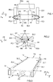
- a cross member (or beam) TS is intended to allow the suspension of an electric driving machine ME of a vehicle, and to be coupled to structural elements ES1 and ES2 of this vehicle.
- these structural elements ES1 and ES2 are what those skilled in the art respectively call left and right stretchers.
- this cross-member TS is made of extruded aluminum, and comprises at least two full longitudinal zones ZLj and in which are defined, in selected locations, holes TF suitable for allowing the attachment of the electric motor machine ME and / or of a vehicle equipment, and / or its coupling to the structural elements ES1 and ES2.
- full is meant here being filled with solid matter. This filling can result from the extrusion phase or from a supply of solid material after the extrusion phase, in hollowed out zones during the latter. The solid zones coexist with the hollow zones ZC characteristic of the extrusion operation.
- the cross-member TS is extruded in an extrusion direction which is intended to be substantially parallel to the transverse direction Y of the vehicle.
- At least one of the longitudinal zones ZLj can extend vertically over a part of the height (along Z) which separates the lower faces FI and upper FS of the cross-member TS (see figure 3 ). But this is not compulsory. Indeed, at least one of the longitudinal zones ZLj can extend vertically over the entire height separating the lower faces FI and upper FS of the crosspiece TS. What is important is that this height makes it possible to define TF holes suitable for effectively ensuring their function.
- the term “longitudinal edge BLk” is understood here to mean an edge (or side) of the cross-member TS which extends between the structural elements ES1 and ES2.
- At least one of the longitudinal zones ZLj can be one of the two longitudinal edges BLk of the crosspiece TS. It will be understood that in this case the longitudinal zone ZLj extends over the entire length of the cross-member TS (substantially in the transverse direction Y). But this is not compulsory (it could indeed extend over part of this length).
- at least one of the longitudinal zones ZLj could be located between two longitudinal edges BLk of the cross-member TS.
- the latter solution can be implemented when there is a need for hole (s) TF in a "central" part of the cross member TS which is located between its two longitudinal edges BLk.
- cross member TS comprises longitudinal zones ZLj, the heavier it is because the latter (ZLj) are filled with solid material.
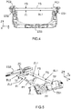
- a hole TF defined in a longitudinal zone ZLj, can be used only for fixing the electric driving machine ME, or only for fixing a vehicle equipment, such as for example a part at least of the power electronics EP (see figure 2 ), or simultaneously with the attachment of the electric drive machine ME and a vehicle equipment, or only with the coupling of the cross-member TS to a structural element ES1 or ES2, or even simultaneously with the coupling of the cross-member TS with a structural element ES1 or ES2 and to the attachment of the ME electric driving machine or vehicle equipment.
- a vehicle equipment such as for example a part at least of the power electronics EP (see figure 2 )
- the TF holes can be tapped in order to allow the screwing of a threaded part of a MF screw or bolt.
- the height of the internal thread of a threaded hole TF is preferably at least equal to around 20 mm when the screw (or bolt) is of the M10 type.
- At least part of the power electronics EP of the vehicle is secured to the upper face FS of the cross member TS by means of fixing means MF (such as for example screws or bolts) which cooperate with holes TF, while the electric driving machine ME is suspended from the underside FS of the cross member TS by means of two fixing lugs PF secured to the latter (TS) at the holes TF.
- fixing means MF such as for example screws or bolts
- these fixing lugs PF may include a hollowed-out central part in which is tightly housed a piece of elastomer PE which is secured to a support lug PS, itself fixedly secured to a part of the electric motor machine ME.
- Each piece of PE elastomer is responsible for filtering the vibrations induced by the electric drive machine ME (preferably in the three directions of space), and has, for example, a circular cylindrical shape.
- the hollowed-out central part of each fixing lug PF is circular.
- each fixing lug PF is secured to the lower face FI of the cross member TS via at least one screw or a bolt MF, and preferably two.
- each PF mounting bracket can, for example, be made of metal (for example aluminum or steel), or of rigid and resistant plastic.
- the electric drive machine ME could be suspended under the underside FS of the cross-member TS by means of two support wedges (or supports) whose upper ends pass through holes defined by machining in the central part of the cross member TS in order to be secured to the upper face FS of the latter (TS), preferably via elastomer parts.
- the upper ends of the supporting wedges are then fixedly secured to the face upper FS, directly or indirectly, by means of screws partially passing through holes TF defined in the central part of the crosspiece TS.
- the electric driving machine ME can also be coupled, via another elastomer part PE ′, to another structural element ES3 of the vehicle.
- This other structural element ES3 can, for example, be what a person skilled in the art calls a cradle.
- the latter (ES3) is generally installed substantially in the longitudinal direction X of the vehicle.
- This other piece of elastomer PE ' is responsible for damping in the longitudinal direction X the vibrations induced by the production of torque.
- this other elastomer part PE ′ is secured to the electric driving machine ME via another fixing lug PF ′ of the latter (ME).
- the cross-member TS can be secured (or coupled) to the structural elements ES1 and ES2 indirectly, via respectively two coupling pieces PC1 and PC2.
- the latter (PC1 and PC2) can, for example, be made of metal (for example aluminum or steel), or of rigid and resistant plastic. But in a variant embodiment not shown, the cross member TS could be secured directly to the structural elements ES1 and ES2.
- the cross-member TS is secured to the structural elements ES1 and ES2 indirectly, respectively via four coupling pieces PC'1 to PC'4.
- the PC'1 and PC'2 coupling parts are rigid and fixedly fixed to the TS cross-member. It will be noted, as illustrated without limitation, that they may be different from each other, or even very different. But they could be the same.
- these coupling pieces PC'1 and PC'2 can be made of metal (for example aluminum or steel), or of rigid and resistant plastic.
- the coupling pieces PC'3 and PC'4 are partially or completely non-rigid and fixedly attached, on the one hand, to the coupling pieces PC'1 and PC'2 and, on the other hand, to the structural elements ES1 and ES2 .
- they include at least one non-rigid part responsible for filtering the vibrations induced by the ME electric driving machine (preferably in the three directions of space).
- This non-rigid part is for example made of elastomer.
- one of the rigid coupling pieces PC'1 can optionally be arranged to ensure an upward offset in the vertical direction Z, while the other rigid coupling piece PC'2 can possibly be arranged to ensure a downward offset in the vertical direction Z.
- the cross member TS can be installed in the vehicle substantially parallel to the transverse direction Y. But this is not compulsory. Indeed, the cross-member TS could be installed in the vehicle in a general direction which is slightly disoriented with respect to the transverse direction Y (in the plane XY). In this case, the disorientation angle can, for example, be between about 3 ° and about 20 °.
- the cross-member TS may possibly comprise on these longitudinal edges BLk at least one boss in the longitudinal direction X.
- This type of boss is intended to allow the fixing of element (s) under the hood of the vehicle, such as for example a hose, a pipe, a pump, an electronic component, a compressor, with positioning in the longitudinal direction X potentially more favorable in terms of layout and / or mounting.
Landscapes
- Engineering & Computer Science (AREA)
- Chemical & Material Sciences (AREA)
- Combustion & Propulsion (AREA)
- Transportation (AREA)
- Mechanical Engineering (AREA)
- Architecture (AREA)
- Structural Engineering (AREA)
- Body Structure For Vehicles (AREA)
- Arrangement Or Mounting Of Propulsion Units For Vehicles (AREA)
- Extrusion Of Metal (AREA)
- Forging (AREA)
Claims (9)
- Querträger (TS), der aus Strangpressaluminium für die Aufhängung einer elektrischen Antriebsmaschine (ME) eines Fahrzeugs hergestellt ist, und der mindestens zwei hohle Längszonen umfasst, die während der Strangpressphase ausgehöhlt werden, dadurch gekennzeichnet, dass die zwei hohlen Längszonen nach der Strangpressphase mit zugefügtem festem Material gefüllt werden, die daher mindestens zwei massive Längszonen (ZLj) bilden, in welchen an ausgewählten Stellen Löcher (TF) definiert sind, die geeignet sind, um eine Befestigung der elektrischen Antriebsmaschine (ME) und/oder einer Ausstattung des Fahrzeugs und/oder einer Kopplung des Querträgers (TS) an Strukturelementen (ES1, ES2) des Fahrzeugs zu erlauben.
- Querträger nach Anspruch 1, dadurch gekennzeichnet, dass mindestens eine der Längszonen (ZLj) ein Längsrand ist.
- Querträger nach einem der Ansprüche 1 und 2, dadurch gekennzeichnet, dass mindestens eine der Längszonen (ZLj) zwischen zwei Längsrändern liegt.
- Querträger nach einem der Ansprüche 1 bis 3, dadurch gekennzeichnet, dass sich mindestens eine der Längszonen (ZLj) vertikal auf einem Teil einer Höhe, die eine untere (FI) und eine obere Fläche (FS) trennt, erstreckt.
- Querträger nach einem der Ansprüche 1 bis 4, dadurch gekennzeichnet, dass er entlang einer Strangpressrichtung stranggepresst ist, die dazu bestimmt ist, im Wesentlichen zu einer Querrichtung des Fahrzeugs, die selbst im Wesentlichen zu Seiten des Fahrzeugs senkrecht ist, parallel zu sein.
- Querträger nach einem der Ansprüche 1 bis 5, dadurch gekennzeichnet, dass mindestens bestimmte der Löcher (TF) Innengewinde gebohrt haben.
- Fahrzeug, das eine elektrische Antriebsmaschine (ME) umfasst, dadurch gekennzeichnet, dass es außerdem einen Querträger (TS) nach einem der vorstehenden Ansprüche umfasst, und an dem die elektrische Antriebsmaschine (ME) aufgehängt ist.
- Fahrzeug nach Anspruch 7, dadurch gekennzeichnet, dass der Querträger (TS) entlang einer Richtung installiert ist, die eine Ausrichtungsabweichung bezüglich einer Querrichtung des Fahrzeugs, die selbst im Wesentlichen zu Seiten des Fahrzeugs senkrecht ist, aufweist.
- Fahrzeug nach einem der Ansprüche 7 und 8, dadurch gekennzeichnet, dass es vom Automobiltyp ist.
Applications Claiming Priority (2)
| Application Number | Priority Date | Filing Date | Title |
|---|---|---|---|
| FR1555235A FR3037289B1 (fr) | 2015-06-09 | 2015-06-09 | Traverse en aluminium extrude et a zones longitudinales pleines, pour la suspension d'une machine electrique motrice d'un vehicule |
| PCT/FR2016/051084 WO2016198758A1 (fr) | 2015-06-09 | 2016-05-10 | Traverse en aluminium extrudé et à zones longitudinales pleines, pour la suspension d'une machine électrique motrice d'un véhicule |
Publications (2)
| Publication Number | Publication Date |
|---|---|
| EP3307578A1 EP3307578A1 (de) | 2018-04-18 |
| EP3307578B1 true EP3307578B1 (de) | 2020-01-15 |
Family
ID=53879666
Family Applications (1)
| Application Number | Title | Priority Date | Filing Date |
|---|---|---|---|
| EP16726139.5A Active EP3307578B1 (de) | 2015-06-09 | 2016-05-10 | Aluminiumstrangpressquerträger mit festen längsbereichen zur befestigung einer elektrischen antriebsmaschine eines fahrzeugs |
Country Status (4)
| Country | Link |
|---|---|
| EP (1) | EP3307578B1 (de) |
| CN (1) | CN107735275B (de) |
| FR (1) | FR3037289B1 (de) |
| WO (1) | WO2016198758A1 (de) |
Cited By (1)
| Publication number | Priority date | Publication date | Assignee | Title |
|---|---|---|---|---|
| EP4606680A1 (de) * | 2024-02-26 | 2025-08-27 | Renault s.a.s | Anordnung mit schwingungsfilterelementen zwischen einem wagenkasten und einem antriebsstrang eines fahrzeugs |
Families Citing this family (5)
| Publication number | Priority date | Publication date | Assignee | Title |
|---|---|---|---|---|
| FR3068668B1 (fr) * | 2017-07-06 | 2019-08-02 | Psa Automobiles Sa | Groupe motopropulseur de vehicule a machine electrique motrice suspendue a une traverse hybride |
| FR3078293B1 (fr) | 2018-02-28 | 2020-01-24 | Psa Automobiles Sa | Groupe motopropulseur de vehicule a machine electrique motrice suspendue a une traverse hybride a pieces de filtrage |
| EP3569480B1 (de) * | 2018-05-15 | 2021-11-17 | Volvo Car Corporation | Elektrofahrzeug |
| DE102018122226A1 (de) * | 2018-09-12 | 2020-03-12 | Dr. Ing. H.C. F. Porsche Aktiengesellschaft | Hilfsrahmen am Fahrschemel eines Kraftfahrzeugs und Kraftfahrzeug |
| DE102023118915A1 (de) | 2023-07-18 | 2025-01-23 | Audi Aktiengesellschaft | Anordnung zur Lagerung einer Antriebseinheit und eines Fahrwerksaggregats an einer Tragstruktur eines Kraftfahrzeugs sowie Kraftfahrzeug |
Family Cites Families (7)
| Publication number | Priority date | Publication date | Assignee | Title |
|---|---|---|---|---|
| FR2702713B1 (fr) * | 1993-03-19 | 1995-04-28 | Renault | Chassis support d'un groupe moto-propulseur . |
| KR100342114B1 (ko) * | 1994-08-10 | 2003-01-24 | 도요다 지도샤 가부시끼가이샤 | 수지제자동차용충격완충부재및그제조방법 |
| DE19939710A1 (de) * | 1999-08-18 | 2001-02-22 | Siemens Ag | Anschlußschienen für elektrische Geräte und Apparate für verschiedene Nennströme |
| DE102010025555A1 (de) * | 2009-07-06 | 2011-01-13 | Ksm Castings Gmbh | Achsträger, insbesondere Vorderachsträger für Kraftfahrzeuge |
| DE102012011797A1 (de) * | 2011-07-05 | 2013-01-10 | Ksm Castings Group Gmbh | Achsträger |
| US20130181485A1 (en) * | 2011-10-21 | 2013-07-18 | Fisker Automotive, Inc. | Rear-wheel drive, plug-in hybrid electric vehicle modular subframe assembly and method |
| CN202541654U (zh) * | 2011-12-31 | 2012-11-21 | 湖南晟通科技集团有限公司 | 客车整体地板 |
-
2015
- 2015-06-09 FR FR1555235A patent/FR3037289B1/fr not_active Expired - Fee Related
-
2016
- 2016-05-10 EP EP16726139.5A patent/EP3307578B1/de active Active
- 2016-05-10 WO PCT/FR2016/051084 patent/WO2016198758A1/fr not_active Ceased
- 2016-05-10 CN CN201680033785.XA patent/CN107735275B/zh active Active
Non-Patent Citations (1)
| Title |
|---|
| None * |
Cited By (2)
| Publication number | Priority date | Publication date | Assignee | Title |
|---|---|---|---|---|
| EP4606680A1 (de) * | 2024-02-26 | 2025-08-27 | Renault s.a.s | Anordnung mit schwingungsfilterelementen zwischen einem wagenkasten und einem antriebsstrang eines fahrzeugs |
| FR3159568A1 (fr) * | 2024-02-26 | 2025-08-29 | Renault Sas | Agencement comprenant des éléments de filtration des vibrations entre une caisse et un groupe motopropulseur de véhicule. |
Also Published As
| Publication number | Publication date |
|---|---|
| EP3307578A1 (de) | 2018-04-18 |
| FR3037289B1 (fr) | 2017-07-14 |
| FR3037289A1 (fr) | 2016-12-16 |
| CN107735275A (zh) | 2018-02-23 |
| WO2016198758A1 (fr) | 2016-12-15 |
| CN107735275B (zh) | 2020-12-29 |
Similar Documents
| Publication | Publication Date | Title |
|---|---|---|
| EP3307578B1 (de) | Aluminiumstrangpressquerträger mit festen längsbereichen zur befestigung einer elektrischen antriebsmaschine eines fahrzeugs | |
| EP3533644B1 (de) | Motorantriebsanlage eines fahrzeugs mit einer elektrischen antriebsmaschine, die an einem hybridträger mit filterteilen aufgehängt ist | |
| FR3047446A1 (fr) | Systeme de suspension d’une machine electrique motrice a double filtrage et double decouplage, pour un vehicule | |
| EP2266829B1 (de) | Schwingungsdämpfungsvorrichtung mit begrenztem Hub | |
| EP3003826B1 (de) | Träger für fahrwerk eines kraftfahrzeugs | |
| FR3068668B1 (fr) | Groupe motopropulseur de vehicule a machine electrique motrice suspendue a une traverse hybride | |
| EP3126209B1 (de) | Verstärkte kraftfahrzeug struktur | |
| EP3423733B1 (de) | Schwingungsdämpfungsvorrichtung zwischen einem ersten schwingungselement und einem zweiten element | |
| FR3022520A1 (fr) | Plancher de vehicule automobile avec podium de renfort composite | |
| FR3122134A1 (fr) | Armature de pare-chocs avant avec pied central | |
| EP3787955B1 (de) | Stützvorrichtung, für eine elektrische antriebsmaschine eines fahrzeugs, die nach bedarf steuerbar ist | |
| EP3983279B1 (de) | Verstärkungsmittel für eine vorderstruktur eines kraftfahrzeuges | |
| EP1847445B1 (de) | Struktur vor einem Kraftfahrzeug und ein entsprechendes Verfahren | |
| FR3060084B1 (fr) | Dispositif de filtration de vibrations a piece asymetrique, pour un mecanisme de changement de rapport d'un vehicule | |
| JP4752746B2 (ja) | エンジンのバランサ装置 | |
| FR3059971A1 (fr) | Fixation simplifiee directe d'un jambage de traverse de poste de conduite de vehicule. | |
| EP3405382A1 (de) | Teil zur verstärkung eines unteren querträgers für eine fensteröffnung | |
| CN106965858B (zh) | 汽车顶部减震配重块安装结构及安装方法 | |
| FR3059972A1 (fr) | Fixation simplifiee d'un jambage de traverse de poste de conduite de vehicule. | |
| FR3140056A1 (fr) | Pièce de renfort pour une pièce d’appui de façade de véhicule automobile | |
| WO2020128178A1 (fr) | Renfort de structure avant de bas de caisse avec fonction appui cric integree | |
| FR2985458A1 (fr) | Dispositif de fixation pour fixer un ensemble mecanique a une structure de caisse de vehicule optimisant performances choc et vibratoire | |
| FR3096333A1 (fr) | Plancher avant, traverse de fixation pour siège avant et véhicule comprenant de tels éléments | |
| FR3089885A1 (fr) | Groupe motopropulseur de véhicule à machine électrique motrice supportée par un élément structurel et couplée à une traverse | |
| FR3081417A1 (fr) | Dispositif de protection d’une batterie de vehicule installee entre des coupelles d’appui de ressort d’une traverse arriere deformable |
Legal Events
| Date | Code | Title | Description |
|---|---|---|---|
| STAA | Information on the status of an ep patent application or granted ep patent |
Free format text: STATUS: THE INTERNATIONAL PUBLICATION HAS BEEN MADE |
|
| PUAI | Public reference made under article 153(3) epc to a published international application that has entered the european phase |
Free format text: ORIGINAL CODE: 0009012 |
|
| STAA | Information on the status of an ep patent application or granted ep patent |
Free format text: STATUS: REQUEST FOR EXAMINATION WAS MADE |
|
| 17P | Request for examination filed |
Effective date: 20171214 |
|
| AK | Designated contracting states |
Kind code of ref document: A1 Designated state(s): AL AT BE BG CH CY CZ DE DK EE ES FI FR GB GR HR HU IE IS IT LI LT LU LV MC MK MT NL NO PL PT RO RS SE SI SK SM TR |
|
| AX | Request for extension of the european patent |
Extension state: BA ME |
|
| DAV | Request for validation of the european patent (deleted) | ||
| DAX | Request for extension of the european patent (deleted) | ||
| STAA | Information on the status of an ep patent application or granted ep patent |
Free format text: STATUS: EXAMINATION IS IN PROGRESS |
|
| 17Q | First examination report despatched |
Effective date: 20190117 |
|
| GRAP | Despatch of communication of intention to grant a patent |
Free format text: ORIGINAL CODE: EPIDOSNIGR1 |
|
| STAA | Information on the status of an ep patent application or granted ep patent |
Free format text: STATUS: GRANT OF PATENT IS INTENDED |
|
| INTG | Intention to grant announced |
Effective date: 20190814 |
|
| GRAS | Grant fee paid |
Free format text: ORIGINAL CODE: EPIDOSNIGR3 |
|
| GRAA | (expected) grant |
Free format text: ORIGINAL CODE: 0009210 |
|
| STAA | Information on the status of an ep patent application or granted ep patent |
Free format text: STATUS: THE PATENT HAS BEEN GRANTED |
|
| AK | Designated contracting states |
Kind code of ref document: B1 Designated state(s): AL AT BE BG CH CY CZ DE DK EE ES FI FR GB GR HR HU IE IS IT LI LT LU LV MC MK MT NL NO PL PT RO RS SE SI SK SM TR |
|
| REG | Reference to a national code |
Ref country code: CH Ref legal event code: EP Ref country code: GB Ref legal event code: FG4D Free format text: NOT ENGLISH |
|
| REG | Reference to a national code |
Ref country code: IE Ref legal event code: FG4D Free format text: LANGUAGE OF EP DOCUMENT: FRENCH |
|
| REG | Reference to a national code |
Ref country code: DE Ref legal event code: R096 Ref document number: 602016028280 Country of ref document: DE |
|
| REG | Reference to a national code |
Ref country code: DE Ref legal event code: R084 Ref document number: 602016028280 Country of ref document: DE |
|
| REG | Reference to a national code |
Ref country code: AT Ref legal event code: REF Ref document number: 1224859 Country of ref document: AT Kind code of ref document: T Effective date: 20200215 |
|
| REG | Reference to a national code |
Ref country code: GB Ref legal event code: 746 Effective date: 20200207 |
|
| REG | Reference to a national code |
Ref country code: NL Ref legal event code: MP Effective date: 20200115 |
|
| REG | Reference to a national code |
Ref country code: LT Ref legal event code: MG4D |
|
| PG25 | Lapsed in a contracting state [announced via postgrant information from national office to epo] |
Ref country code: FI Free format text: LAPSE BECAUSE OF FAILURE TO SUBMIT A TRANSLATION OF THE DESCRIPTION OR TO PAY THE FEE WITHIN THE PRESCRIBED TIME-LIMIT Effective date: 20200115 Ref country code: NO Free format text: LAPSE BECAUSE OF FAILURE TO SUBMIT A TRANSLATION OF THE DESCRIPTION OR TO PAY THE FEE WITHIN THE PRESCRIBED TIME-LIMIT Effective date: 20200415 Ref country code: RS Free format text: LAPSE BECAUSE OF FAILURE TO SUBMIT A TRANSLATION OF THE DESCRIPTION OR TO PAY THE FEE WITHIN THE PRESCRIBED TIME-LIMIT Effective date: 20200115 Ref country code: NL Free format text: LAPSE BECAUSE OF FAILURE TO SUBMIT A TRANSLATION OF THE DESCRIPTION OR TO PAY THE FEE WITHIN THE PRESCRIBED TIME-LIMIT Effective date: 20200115 Ref country code: PT Free format text: LAPSE BECAUSE OF FAILURE TO SUBMIT A TRANSLATION OF THE DESCRIPTION OR TO PAY THE FEE WITHIN THE PRESCRIBED TIME-LIMIT Effective date: 20200607 |
|
| PG25 | Lapsed in a contracting state [announced via postgrant information from national office to epo] |
Ref country code: IS Free format text: LAPSE BECAUSE OF FAILURE TO SUBMIT A TRANSLATION OF THE DESCRIPTION OR TO PAY THE FEE WITHIN THE PRESCRIBED TIME-LIMIT Effective date: 20200515 Ref country code: BG Free format text: LAPSE BECAUSE OF FAILURE TO SUBMIT A TRANSLATION OF THE DESCRIPTION OR TO PAY THE FEE WITHIN THE PRESCRIBED TIME-LIMIT Effective date: 20200415 Ref country code: HR Free format text: LAPSE BECAUSE OF FAILURE TO SUBMIT A TRANSLATION OF THE DESCRIPTION OR TO PAY THE FEE WITHIN THE PRESCRIBED TIME-LIMIT Effective date: 20200115 Ref country code: GR Free format text: LAPSE BECAUSE OF FAILURE TO SUBMIT A TRANSLATION OF THE DESCRIPTION OR TO PAY THE FEE WITHIN THE PRESCRIBED TIME-LIMIT Effective date: 20200416 Ref country code: SE Free format text: LAPSE BECAUSE OF FAILURE TO SUBMIT A TRANSLATION OF THE DESCRIPTION OR TO PAY THE FEE WITHIN THE PRESCRIBED TIME-LIMIT Effective date: 20200115 Ref country code: LV Free format text: LAPSE BECAUSE OF FAILURE TO SUBMIT A TRANSLATION OF THE DESCRIPTION OR TO PAY THE FEE WITHIN THE PRESCRIBED TIME-LIMIT Effective date: 20200115 |
|
| REG | Reference to a national code |
Ref country code: DE Ref legal event code: R097 Ref document number: 602016028280 Country of ref document: DE |
|
| PG25 | Lapsed in a contracting state [announced via postgrant information from national office to epo] |
Ref country code: LT Free format text: LAPSE BECAUSE OF FAILURE TO SUBMIT A TRANSLATION OF THE DESCRIPTION OR TO PAY THE FEE WITHIN THE PRESCRIBED TIME-LIMIT Effective date: 20200115 Ref country code: CZ Free format text: LAPSE BECAUSE OF FAILURE TO SUBMIT A TRANSLATION OF THE DESCRIPTION OR TO PAY THE FEE WITHIN THE PRESCRIBED TIME-LIMIT Effective date: 20200115 Ref country code: ES Free format text: LAPSE BECAUSE OF FAILURE TO SUBMIT A TRANSLATION OF THE DESCRIPTION OR TO PAY THE FEE WITHIN THE PRESCRIBED TIME-LIMIT Effective date: 20200115 Ref country code: SK Free format text: LAPSE BECAUSE OF FAILURE TO SUBMIT A TRANSLATION OF THE DESCRIPTION OR TO PAY THE FEE WITHIN THE PRESCRIBED TIME-LIMIT Effective date: 20200115 Ref country code: RO Free format text: LAPSE BECAUSE OF FAILURE TO SUBMIT A TRANSLATION OF THE DESCRIPTION OR TO PAY THE FEE WITHIN THE PRESCRIBED TIME-LIMIT Effective date: 20200115 Ref country code: EE Free format text: LAPSE BECAUSE OF FAILURE TO SUBMIT A TRANSLATION OF THE DESCRIPTION OR TO PAY THE FEE WITHIN THE PRESCRIBED TIME-LIMIT Effective date: 20200115 Ref country code: SM Free format text: LAPSE BECAUSE OF FAILURE TO SUBMIT A TRANSLATION OF THE DESCRIPTION OR TO PAY THE FEE WITHIN THE PRESCRIBED TIME-LIMIT Effective date: 20200115 Ref country code: DK Free format text: LAPSE BECAUSE OF FAILURE TO SUBMIT A TRANSLATION OF THE DESCRIPTION OR TO PAY THE FEE WITHIN THE PRESCRIBED TIME-LIMIT Effective date: 20200115 |
|
| RAP2 | Party data changed (patent owner data changed or rights of a patent transferred) |
Owner name: PSA AUTOMOBILES SA |
|
| REG | Reference to a national code |
Ref country code: AT Ref legal event code: MK05 Ref document number: 1224859 Country of ref document: AT Kind code of ref document: T Effective date: 20200115 |
|
| PLBE | No opposition filed within time limit |
Free format text: ORIGINAL CODE: 0009261 |
|
| STAA | Information on the status of an ep patent application or granted ep patent |
Free format text: STATUS: NO OPPOSITION FILED WITHIN TIME LIMIT |
|
| 26N | No opposition filed |
Effective date: 20201016 |
|
| PG25 | Lapsed in a contracting state [announced via postgrant information from national office to epo] |
Ref country code: CH Free format text: LAPSE BECAUSE OF NON-PAYMENT OF DUE FEES Effective date: 20200531 Ref country code: MC Free format text: LAPSE BECAUSE OF FAILURE TO SUBMIT A TRANSLATION OF THE DESCRIPTION OR TO PAY THE FEE WITHIN THE PRESCRIBED TIME-LIMIT Effective date: 20200115 Ref country code: AT Free format text: LAPSE BECAUSE OF FAILURE TO SUBMIT A TRANSLATION OF THE DESCRIPTION OR TO PAY THE FEE WITHIN THE PRESCRIBED TIME-LIMIT Effective date: 20200115 Ref country code: LI Free format text: LAPSE BECAUSE OF NON-PAYMENT OF DUE FEES Effective date: 20200531 Ref country code: IT Free format text: LAPSE BECAUSE OF FAILURE TO SUBMIT A TRANSLATION OF THE DESCRIPTION OR TO PAY THE FEE WITHIN THE PRESCRIBED TIME-LIMIT Effective date: 20200115 |
|
| PG25 | Lapsed in a contracting state [announced via postgrant information from national office to epo] |
Ref country code: SI Free format text: LAPSE BECAUSE OF FAILURE TO SUBMIT A TRANSLATION OF THE DESCRIPTION OR TO PAY THE FEE WITHIN THE PRESCRIBED TIME-LIMIT Effective date: 20200115 Ref country code: PL Free format text: LAPSE BECAUSE OF FAILURE TO SUBMIT A TRANSLATION OF THE DESCRIPTION OR TO PAY THE FEE WITHIN THE PRESCRIBED TIME-LIMIT Effective date: 20200115 |
|
| REG | Reference to a national code |
Ref country code: BE Ref legal event code: MM Effective date: 20200531 |
|
| PG25 | Lapsed in a contracting state [announced via postgrant information from national office to epo] |
Ref country code: LU Free format text: LAPSE BECAUSE OF NON-PAYMENT OF DUE FEES Effective date: 20200510 |
|
| PG25 | Lapsed in a contracting state [announced via postgrant information from national office to epo] |
Ref country code: IE Free format text: LAPSE BECAUSE OF NON-PAYMENT OF DUE FEES Effective date: 20200510 |
|
| PG25 | Lapsed in a contracting state [announced via postgrant information from national office to epo] |
Ref country code: BE Free format text: LAPSE BECAUSE OF NON-PAYMENT OF DUE FEES Effective date: 20200531 |
|
| PG25 | Lapsed in a contracting state [announced via postgrant information from national office to epo] |
Ref country code: TR Free format text: LAPSE BECAUSE OF FAILURE TO SUBMIT A TRANSLATION OF THE DESCRIPTION OR TO PAY THE FEE WITHIN THE PRESCRIBED TIME-LIMIT Effective date: 20200115 Ref country code: MT Free format text: LAPSE BECAUSE OF FAILURE TO SUBMIT A TRANSLATION OF THE DESCRIPTION OR TO PAY THE FEE WITHIN THE PRESCRIBED TIME-LIMIT Effective date: 20200115 Ref country code: CY Free format text: LAPSE BECAUSE OF FAILURE TO SUBMIT A TRANSLATION OF THE DESCRIPTION OR TO PAY THE FEE WITHIN THE PRESCRIBED TIME-LIMIT Effective date: 20200115 |
|
| PG25 | Lapsed in a contracting state [announced via postgrant information from national office to epo] |
Ref country code: MK Free format text: LAPSE BECAUSE OF FAILURE TO SUBMIT A TRANSLATION OF THE DESCRIPTION OR TO PAY THE FEE WITHIN THE PRESCRIBED TIME-LIMIT Effective date: 20200115 Ref country code: AL Free format text: LAPSE BECAUSE OF FAILURE TO SUBMIT A TRANSLATION OF THE DESCRIPTION OR TO PAY THE FEE WITHIN THE PRESCRIBED TIME-LIMIT Effective date: 20200115 |
|
| REG | Reference to a national code |
Ref country code: DE Ref legal event code: R081 Ref document number: 602016028280 Country of ref document: DE Owner name: STELLANTIS AUTO SAS, FR Free format text: FORMER OWNER: PSA AUTOMOBILES S.A., POISSY, FR |
|
| PGFP | Annual fee paid to national office [announced via postgrant information from national office to epo] |
Ref country code: DE Payment date: 20250423 Year of fee payment: 10 |
|
| PGFP | Annual fee paid to national office [announced via postgrant information from national office to epo] |
Ref country code: GB Payment date: 20250423 Year of fee payment: 10 |
|
| PGFP | Annual fee paid to national office [announced via postgrant information from national office to epo] |
Ref country code: FR Payment date: 20250423 Year of fee payment: 10 |