EP3307946B1 - System und verfahren zur überwachung eines bandes - Google Patents
System und verfahren zur überwachung eines bandes Download PDFInfo
- Publication number
- EP3307946B1 EP3307946B1 EP16733770.8A EP16733770A EP3307946B1 EP 3307946 B1 EP3307946 B1 EP 3307946B1 EP 16733770 A EP16733770 A EP 16733770A EP 3307946 B1 EP3307946 B1 EP 3307946B1
- Authority
- EP
- European Patent Office
- Prior art keywords
- nip
- continuous band
- felt
- segments
- roll
- Prior art date
- Legal status (The legal status is an assumption and is not a legal conclusion. Google has not performed a legal analysis and makes no representation as to the accuracy of the status listed.)
- Active
Links
Images











Classifications
-
- G—PHYSICS
- G01—MEASURING; TESTING
- G01L—MEASURING FORCE, STRESS, TORQUE, WORK, MECHANICAL POWER, MECHANICAL EFFICIENCY, OR FLUID PRESSURE
- G01L5/00—Apparatus for, or methods of, measuring force, work, mechanical power, or torque, specially adapted for specific purposes
- G01L5/0061—Force sensors associated with industrial machines or actuators
- G01L5/0076—Force sensors associated with manufacturing machines
- G01L5/0085—Force sensors adapted for insertion between cooperating machine elements, e.g. for measuring the nip force between rollers
-
- D—TEXTILES; PAPER
- D21—PAPER-MAKING; PRODUCTION OF CELLULOSE
- D21F—PAPER-MAKING MACHINES; METHODS OF PRODUCING PAPER THEREON
- D21F1/00—Wet end of machines for making continuous webs of paper
- D21F1/0027—Screen-cloths
-
- D—TEXTILES; PAPER
- D21—PAPER-MAKING; PRODUCTION OF CELLULOSE
- D21F—PAPER-MAKING MACHINES; METHODS OF PRODUCING PAPER THEREON
- D21F3/00—Press section of machines for making continuous webs of paper
-
- D—TEXTILES; PAPER
- D21—PAPER-MAKING; PRODUCTION OF CELLULOSE
- D21F—PAPER-MAKING MACHINES; METHODS OF PRODUCING PAPER THEREON
- D21F3/00—Press section of machines for making continuous webs of paper
- D21F3/02—Wet presses
-
- D—TEXTILES; PAPER
- D21—PAPER-MAKING; PRODUCTION OF CELLULOSE
- D21F—PAPER-MAKING MACHINES; METHODS OF PRODUCING PAPER THEREON
- D21F3/00—Press section of machines for making continuous webs of paper
- D21F3/02—Wet presses
- D21F3/08—Pressure rolls
-
- D—TEXTILES; PAPER
- D21—PAPER-MAKING; PRODUCTION OF CELLULOSE
- D21F—PAPER-MAKING MACHINES; METHODS OF PRODUCING PAPER THEREON
- D21F7/00—Other details of machines for making continuous webs of paper
- D21F7/08—Felts
-
- D—TEXTILES; PAPER
- D21—PAPER-MAKING; PRODUCTION OF CELLULOSE
- D21G—CALENDERS; ACCESSORIES FOR PAPER-MAKING MACHINES
- D21G9/00—Other accessories for paper-making machines
- D21G9/0009—Paper-making control systems
- D21G9/0036—Paper-making control systems controlling the press or drying section
-
- G—PHYSICS
- G01—MEASURING; TESTING
- G01L—MEASURING FORCE, STRESS, TORQUE, WORK, MECHANICAL POWER, MECHANICAL EFFICIENCY, OR FLUID PRESSURE
- G01L5/00—Apparatus for, or methods of, measuring force, work, mechanical power, or torque, specially adapted for specific purposes
- G01L5/0061—Force sensors associated with industrial machines or actuators
- G01L5/0076—Force sensors associated with manufacturing machines
Definitions
- the present invention relates generally to papermaking and, more particularly to monitoring one or more components in the papermaking process.
- the fabric wire continuously supports the fibrous web and transfers it to another fabric called a felt which advances it through the various dewatering equipment that effectively removes the desired amount of liquid from the web. Water from the web is pressed into the wet felt and then can be removed as the wet felt passes a suction box. Dry felts can also be used to support the fibrous web through steam dryers.
- the continuous band can include a plurality of detectable marks along at least a portion of a surface of the continuous band, wherein at least one distinctive mark of the plurality of detectable marks is different than all of the other marks.
- the plurality of marks may be evenly spaced.
- the structure for generating a periodically occurring starting reference includes a detector proximate to the surface of the continuous band for detecting each of the plurality of detectable marks traveling by the detector, wherein each of the plurality of detectable marks traveling by the detector defines a respective event; and a signal generator in communication with the detector for generating the starting reference each time the one distinctive mark is detected.
- the detectable marks can, for example, be optically detectable, magnetically detectable, detectable using infra-red radiation, detectable using sonic waves, detectable using X-rays, or detectable based on radioactive emissions.
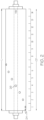
- a sensing roll 10 and a mating roll 11 define a nip 12 receiving a fibrous web 16, such as a paper web, to apply pressure to the web 16. It is contemplated that, in some cases, a continuous band felt may support the web such that the felt and the web enter the nip 12.
- the sensing roll 10 comprises an inner base roll 20 and an outer roll cover 22.
- a set 24 of sensors 26 is disposed at least partially in the roll cover 22.
- the set 24 of sensors 26 may be disposed along a line that spirals around the entire length of the roll 10 in a single revolution to define a helical pattern, which is a common sensor geometry arrangement for roll covers.
- the helical pattern is merely an example and any arrangement is contemplated in which at least one sensor is placed at each axial position, anywhere along the circumference, at which data is to be collected.
- Each sensor 26 can, for example, measure the pressure that is being exerted on the sensor when it enters a region of the nip 12 between the rolls 10 and 11.
- the set 24 of sensors 26 may be positioned in the sensing roll 10, for example, at different axial locations or segments along the sensing roll 10, wherein the axial segments are preferably equally sized.
- the set 24 of sensors 26 may be linearly arranged so as to define a line of sensors, i.e., all sensors reside at the same circumferential location.
- a line of sensors i.e., all sensors reside at the same circumferential location.
- sensors 26 may be referred to as a pressure sensor, for example, but other types of sensors are also contemplated such as, for example, temperature sensors.
- the nip pressure profile has variability that can be termed cross-directional variability as it is the variability of average pressure per cross-direction position across the nip.
- Another type of variability represents the variability of the high speed measurements at each position in the single line of sensors. This variability represents the variability of other equipment in the paper making process such as, for example, wires and felts and also including the rotational variability of the mating roll, i.e., the roll nipped to the sensing roll.
- the third variability in the nip profile includes the variability of multiple sensors, discussed below, at each cross-directional position of the roll. This variability represents the "rotational variability" of the sensing roll as it rotates through its plurality of sensing positions and can only be seen by having a plurality of sensors in the same position.
- each of the second plurality of sensors is located in one of the 14 axial segments of the sensing roll.
- Each sensor of the first plurality has a corresponding sensor from the second plurality located in a same axial segment of the sensing roll.
- the first plurality of sensors can be disposed along a line that spirals around the entire length of the roll in a single revolution to define a helical pattern.
- the second plurality of sensors can be disposed along a line that spirals around the entire length of the roll in a single revolution to define a helical pattern.
- the first and second pluralities of sensors can be separated from one another by 180 degrees. Each sensor measures the pressure that is being exerted on the sensor when it enters a region of a nip.
- first and second pluralities of sensors may be linearly arranged so as to define first and second lines of sensors, which are spaced approximately 180 degrees apart.
- first and second lines of sensors which are spaced approximately 180 degrees apart.
- Various alternative configurations of a plurality of sensors are also contemplated.
- a plurality of sensors could be helically arranged in a line that spirals, in two revolutions, around the entire length of roll.
- a particular sensor 26 may not always enter the region of the nip 12 with the same circumferential portion of the mating roll 11 as it did in a previous rotation.
- This behavior can be utilized to create data maps corresponding to the surface of the mating roll 11. Different average pressure matrices, each collected and built during different periods of time can be compared with one another to investigate how they vary from one another. Variability between the different data maps can indicate possible problems with the mating roll 11, such as roll surface irregularities, bearing wear, and roll flexing. Variability analysis of the sensor data may also indicate possible problems with upstream or downstream processing equipment, e.g., upstream rolls, an upstream forming wire, an upstream felt or downstream rolls.
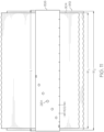
- the sensing and mating rolls 10 and 11 may be each separated into 14 axial segments. All of the axial segments on the sensing roll 10 may or may not be of the same length, and all of the axial segments on the mating roll 11 also may or may not be of the same length. In the illustrated embodiment, it is presumed that all of the axial segments on the sensing roll 10 are of the same length and all of the axial segments on the mating roll 11 are of the same length.
- the axial segments on the sensing roll 10 may be aligned with the axial segments on the mating roll 11.
- the mating roll 11 may be separated into individual circumferential segments such as, for example, 22 circumferential segments, all of substantially the same dimension.
- Fig. 3 not according to the invention illustrates how rotation of the sensing roll 10 and the mating roll 11 can change a circumferential segment of the mating roll 11 that enters a nip region coincidentally with a sensor on each rotation of the sensing roll 10.
- Fig. 3 is presented as series of position snapshots from 1 to 23 of the rotating sensing roll 10 which also correspond to 22 rotations of the sensing roll 10 and 23 rotations of the mating roll 11.
- the left-most portion of Fig. 3 shows a starting position (i.e., where a first sensor reading is collected) and the right-most position of the two rolls 10 and 11 after 22 rotations of the sensing roll 10 after the first sensor reading was collected.
- circumferential segment #1 of the mating roll 11 is positioned in the region of the nip 12 along with the sensor 26A.
- the mating roll 11, in this example, is rotating slightly faster than the sensing roll 10 such that at a second position snapshot following a complete rotation from the starting position, the sensor 26A is once again positioned in the region of the nip 12 but the mating roll 11 has rotated so that circumferential segment #2 is in the region of the nip 12.
- the values of Fig. 3 are selected just as examples to illustrate with concrete numbers operating principles of the present invention. In accordance with the example values of Fig. 3 , when the sensing roll had completed 22 rotations, the mating roll 11 has completed 23 rotations.
- the period of the mating roll would be an integer ratio of the period of the sensing roll. Hence it is very unlikely that a stationary pattern would be maintained between these rolls and this would tend to even out the sampling of tracking segments, discussed below.
- the nip pressure measured by the one sensor 26A may vary during sequential roll rotations due to the change in pressure caused by the mating roll 11.
- mapping readings, or signals, from each sensor 26 of the set 24 over time to see how the pressure readings, or signals, vary for each sensor due to each sensor entering the region of the nip 12 concurrently with different circumferential segments of the mating roll 11.
- the mapped data may be used to determine possible problems with the mating roll 11 and, as more fully described below, data collection can be performed involving possible problems related to upstream or downstream processing equipment other than the sensing roll 10 and the mating roll 11.
- sensing and mating rolls 10 and 11 will be used to illustrate the principles of this invention; however all principles are applicable to upstream and downstream processing equipment, such as upstream and downstream rolls, an upstream forming wire or an upstream felt.
- the mating roll 11 may have rotational characteristics that generate, for example, a sinusoidal pressure pattern which is 55158 N/m 2 (8 pounds per square inch (psi) peak-to-peak).
- a sinusoidal pressure pattern which is 55158 N/m 2 (8 pounds per square inch (psi) peak-to-peak).
- the pressure pattern is "0" when circumferential segment #1 of the mating roll 11 is in the region of the nip 12.
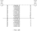
- Figs. 4A and 4B are a table of how collecting 51 sensor readings from sensor 26A would be associated with the different circumferential segments of the mating roll 11.
- the left column 402 is the sequential number assigned to the sensor reading and the middle column 404 represents a pressure reading value from sensor 26A according to the sinusoidal pattern described above and right column 406 is the circumferential segment of the mating roll 11 in the region of the nip when a corresponding pressuring reading is taken from the sensor 26A.
- Each pressure reading value is time-synchronized with the period of rotation of the mating roll 11 by associating that value with one of the circumferential segments of the mating roll 11 that was in the region of the nip 12 when the pressure reading was sensed.
- the length of each time segment is the mating roll period divided by the number of predefined time segments.
- the predefined number of time segments may correspond to a predefined number of mating roll circumferential segments.
- a period of the sensing roll 10 can be described as being x time segments smaller/larger than a period of the mating roll 11. For example, according to Fig.
- the sensing roll 10 may have a period that is 1.0 mating roll time segment more than the period of the mating roll 11 (equivalently, the mating roll 11 can have a period that is 1.0 mating roll time segment smaller than the period of the sensing roll). In such an example, as the sensing roll 10 makes one complete revolution, the mating roll 11 will make more than a complete revolution by an amount equal to 1.0 mating roll time segment due to it having a smaller period than the sensing roll 10.
- the 22 time segments of the mating roll period can correspond to 22 circumferential segments around the mating roll 11.
- that concept can correspond to a physical circumference of the mating roll 11, wherein each individual time segment of the mating roll period also corresponds to a circumferential segment around the mating roll 11.
- differences in rotational periods between the sensing roll 10 and the mating roll 11 measured in units of "time segments” can just as easily be considered in units of "circumferential segments.”
- reference to "circumferential segments" is provided as an aid in understanding aspects of an example embodiment of the present invention.
- One way involves indexing a particular one of the 22 mating roll segments with a trigger signal that is fired each time the mating roll 11 completes one revolution; a time period since the last trigger signal can be used to determine which of the 22 segments (measured relative to the indexed segment) is in the nip 12. For example, if the time between each firing of the trigger signal is 220 ms, then each time segment is 10.0 ms, which corresponds to one of the 22 mating roll circumferential segments.
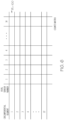
- each row of Fig. 6 represents one of the 22 mating roll circumferential segments (or time segments) and each column represents one of the 14 axially arranged sensors 26 and, thus, each cell represents one of the possible 308 permutations.
- Each column also corresponds to a mating roll outer surface portion at an axial location aligned with and corresponding to the sensor 26 assigned that column.
- Each cell represents a combination of a sensor number (or axial segment number) and a particular mating roll circumferential segment (or time segment).
- the cell 200 still represents a value that is related to sensor number 14 (or axial segment 14, out of 1-14 axial segments, of the mating roll 11) and circumferential segment 1 but, in this example, the value is a cumulative total of pressure readings, e.g., in N/m 2 (pounds/inch 2 ), acquired by the sensor for that circumferential segment during a plurality of rotations of the sensing roll 10.
- N/m 2 pounds/inch 2
- an average pressure matrix depicted in Fig. 8 can be calculated.
- cell 100 includes the number of pressure readings associated with sensor number 14 (or axial segment 14 of the mating roll 11) and circumferential segment number 1 while cell 200 includes the total or summation of all those pressure readings.
- dividing cell 200 by cell 100 provides an average pressure value for that particular permutation of sensor number and mating roll circumferential segment number which entered the region of the nip 12 concurrently.
- the matrix of Fig. 8 not according to the invention represents an average pressure value that is sensed for each particular sensor number and mating roll circumferential segment number. The length of time such data is collected determines how many different pressure readings are used in such calculations.
- the raw pressure readings, or pressure signals, from the sensors 26 can be affected by a variety of components in the system that move the web of material.
- the average values in the average pressure matrix of Fig. 8 are related to variability synchronized to the mating roll 11.
- variability in a cross direction (CD) shown in Fig. 2 .
- One measure of this CD variability is captured by calculating an average for each column of the average pressure matrix.
- the average pressure matrix of Fig. 8 can also include a row 302 that represents a column average value.
- Each of the 14 columns may have 22 cells that can be averaged together to calculate an average value for that column.
- cell 304 would be the average value in the 22 cells of the second column of the average pressure matrix.
- the collection would have a tendency to collect only evenly numbered time/circumferential segments in the short term (i.e., evenly numbered segments are those that are offset an even number of segments from a starting segment) until sufficient time has passed to move the collection into the odd numbered time/circumferential segments.
- evenly numbered segments are those that are offset an even number of segments from a starting segment
- Combining collection sessions separated by a long time delay may help to shift the collection so that data is more uniformly captured for all the different time/circumferential segments because there is no expectation that the period of the mating roll will be related to arbitrary time gaps between collection sessions.
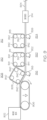
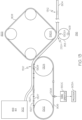
- Fig. 9 illustrates an exemplary process and system configuration in accordance with the principles of the present invention in which each of the various circles represents a rotating component (e.g. a roll) that helps propel a web of material 904 through the process/system.
- the process starts at a headbox 902 where a fiber slurry is distributed over a wire mesh 906 which allows liquid to readily drain from the slurry. From the wire mesh 906, the web of material 904 travels to a first wet felt station 908 that helps dry the web of material 904.
- a felt 909 at the first station 908 is a continuous band arranged to travel in a loop pattern around a plurality of rolls 940.
- the felt 909 enters a press area 916 between one of the rolls 940 and a sensing roll 918 with the web of material 904.
- the sensing roll 918 may operate similar to the sensing roll 10 of Fig. 1 .
- Downstream from the wet felt station 908 is another wet felt station 910 having its own felt 911 traveling in a loop pattern around another set of four rolls 941.
- the last wet felt station 912 has a felt 913 traveling in a loop pattern around another set of four rolls 942.
- the felt 913 together with the web of material 904 is pressed by one of the rolls 942 and a second sensing roll 926 in a third press region 924.
- the felts 909, 911, 913 are pressed into the web of material in their respective press regions 916, 920, 924 to absorb liquid from the web of material 904.
- the web of material 904 is drier after passing through the wet felt stations 908, 910, 912.
- drier it is meant that the fibers in the web of material 904 have a higher percentage by weight of fibers after the wet felt stations than before.
- Additional drying can be performed, however, by separate dryers 914 before the web of material 904 progresses further downstream in the process of Fig. 9 .
- the various felts and rolls of Fig 9 , and the spacing between the different stations are not shown to scale but are provided to simplify description of various aspects of different embodiments of the present invention.
- the web of material 904 does not travel unsupported for long distances.
- the web of material 904 will be removed from one felt and be picked up by a next-downstream felt.
- the web of material can be supported by other supporting rolls and by tension between various rolls.
- a felt can have variations in its material that cause different effects on the web of material 904. For example, seams, worn spots, or even holes, may not be as effective at removing liquid from the web of material 904 as portions of the felt 909 that are in good condition. Thus, some regions of the web of material 904 may have more or less water relative to other regions of the web of material 904 due to variations in the felt 909, i.e., a worn portion of the felt 909 may not remove as much moisture from a region of the web of material that it engages as compared to a portion of the felt that is in good condition and engages another region of the web material.
- a pressure sensed by a sensor on a sensing roll may be greater than when a drier region of the web material 904 passes through the nip.
- the felts 909, 911, 913 may be porous in construction and, thus, some portions of a felt may become clogged with debris, fibers, or other contaminants.
- a pressure sensed by a sensor on a sensing roll may be greater than when the other regions that experienced more moisture being removed pass through the nip.
- a pressure sensed by a sensor on a sensing roll may be greater than when a non-clogged portion of the felt passes through the nip.
- a pressure reading sensed in a nip can reveal effects that a felt had on the web of material 904 upstream of that nip in addition to revealing effects from a felt passing through the nip.
- the felt 913 may be separated into a predefined number of axial segments, such as 14 in the illustrated embodiment, such that the 14 axial segments of the felt 913 are axially aligned with 14 axially spaced apart sensors 26 provided on the sensing roll 926.
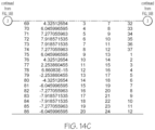
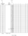
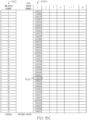
- each pressure reading value in column 404A can also be time-synchronized with the period of rotation of the felt 913 by associating that value with one of the 31 tracking segments, in column 1402, of the felt 913 that was in the region of the nip 1201 when the pressure reading was sensed.
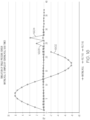
- 14A-14C also shows how collecting 86 sensor readings from the sensor 26A (one of 14 pressure sensors on the sensing roll 926) would be associated with different time-based tracking segments, shown in column 1404 which, in turn, can be correlated to the different physical circumferential tracking segments (e.g., 37 physical tracking segments with only 1202A, 1202B, 1202C, 1202G being designated in Fig. 12A ) of the felt 911.
- the left column 402A is the sequential number assigned to the sensor reading and the next column 404A represents a simulated raw pressure reading sensed at the region of the nip 1201 by the sensor 26A on the sensing roll 926.
- each such pressure reading will have a value that is related to the regions of the web of material 904 passing through the nip 1201.
- the portion 1207 of the felt 911 is located at the circumferential segment 1202G of the felt 911, which segment 1202G may define physical circumferential segment #7, and at an axial location that is axially aligned with the pressure sensor 26A on the sensing roll 926 in the downstream nip 1201.
- the felt portion 1207 may be damaged such that it does not remove as much moisture from a region of the web of material 904 it contacts as compared to other felt portions that remove a greater amount of moisture from the web of material regions they contact.
- the felt portion 1207 removes less moisture content from a corresponding web of material region that it contacts, that web of material region, in turn, causes an increase in pressure in the region of the nip 1201, e.g., of approximately 13789.5 N/m 2 (2 psi) in the illustrated example, as compared to a pressure increase of about 0 psi for all other web of material regions.
- Time-synchronizing the values in column 404A with the period of rotation of the felt 911 can be accomplished by associating that pressure reading value with one of the 37 time-based tracking segments of the period of rotation of the felt 911 that correspond to when the pressure reading was sensed.
- the reference position 1205 on the felt 911 can make 1 complete rotation around the loop pattern around the rolls 941 in the same amount of time that the sensing roll 926 in the downstream nip 1201 makes 37 rotations.
- the felt 911 advances by the length of one of the physical tracking segments (e.g., 1202A) for every rotation of the sensing roll 926.
- the portion 1207 of the felt 911 is located at the circumferential segment 1202G of the felt 911, which segment 1202G may define the physical circumferential segment #7 and at an axial location that is axially aligned with the pressure sensor 26A on the sensing roll 926 in the downstream nip 1201.
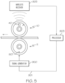
- a signal generator 900B generates a periodic time reference signal when the reference position 1205 of the felt 911 is adjacent the signal generator 900B. This is the reference signal from which a time-based tracking segment of the period of rotation of the felt 911 can be calculated as the sensor 26A on sensing roll 926 passes through the region of the nip 1201.
- the processor 903 will determine the elapsed time period in 1/37 increments since the last reference signal was generated by the signal generator 900B.
- sensor readings from the region of the nip 1201 could also be arranged, or stored, in a manner time-synchronized with the period of rotation of the felt 911.
- the time-based tracking segment numbers (e.g., time-based tracking segment #25) refer to logical segments of the period of rotation of the felt 911 which have occurred from when the reference signal was generated by the signal generator 900B until a pressure reading is sensed and generated by the pressure sensor 26A of the sensing roll 926.
- these initial time-based tracking segment numbers do not necessarily correspond to an identical physical circumferential segment on the felt 911 as measured from the reference location 1205.
- a region of the web of material in the region of the nip 1201 concurrently with sensor 26A may arrive at the 25 th time segment of the period of rotation of the felt 911 but that region of the web of material 904 was not necessarily pressed in the nip region 1203 by the physical 25 th circumferential segment of the felt 911 as measured from the reference location 1205.
- variations in the felt 911 while in the nip 1203 can impact the amount of moisture in the region of the web of material 904 concurrently in the nip 1203 and also the thickness of caliper of the web.
- the rotating felt 911 could include multiple, evenly-spaced marks that could be detected (e.g., optically) as each such mark passes a sensor location.
- the marks would function so as to separate the felt 911 (or 913) into different segments and a counter, or similar circuitry, would increment a count each time a mark was detected so that any collected data could be associated with one of the segments of the felt 911.
- a reference mark could be distinctive from all the other marks such that when the sensor detects the reference mark, the counter circuitry resets and starts counting from an initial value (e.g., "0" or "1").
- the region of the nip 1201 is located downstream a distance from the region of the nip 1203 that is an integer multiple of the felt length L F .
- Fig. 12B shows, when the reference location 1205 is at its position to generate a new time reference signal, there is a segment (e.g., segment #24) that is touching the web of material 904.
- segment #24 is the only felt segment ever in the nip 1203 each time a new time reference signal is generated, it is designated as a "felt touch reference segment.”
- each web of material region 1260, 1270, 1272, 1274, 1276 has a length of 1/37 th of the length L F of the felt 911 corresponding to a time period ⁇ /37 long.
- the region of the web of material 904 that is in the region of the nip 1201 was also previously in the region of the nip 1203 concurrently with the circumferential tracking segment #25 of the felt 911.
- each time-based tracking segment can be easily correlated to a physical circumferential tracking segment of the felt 911.
- Fig. 12C illustrates a slight modification to the arrangement of Fig. 12B in which the region of the nip 1201 happens to be, for example purposes, a distance from the region of the nip 1203 that is not an integer multiple of the length L F of the felt 911.
- the distance between the region of the nip 1201 and the region of the nip 1203 in Fig. 12C has an additional span or distance y .
- the amount of time it takes the web of material 904 to travel the extra distance y equals 10 37 ⁇ ⁇ .
- a sensor reading from the region of the nip 1201 occurring during the first time-based tracking segment 0 ⁇ t ⁇ 1 37 ⁇ ⁇ will involve a region of the web of material 904 that was also previously in the region of the nip 1203 concurrently with the circumferential segment #14 (e.g., 10 time segments before the "felt touch reference segment" (i.e., #24 in the illustrated embodiments of Fig. 12B and 12C ) was in the region of the nip 1203. So, more generally:
- the index value x of a particular time-based tracking segment can be calculated independently from calculating the index value q of the corresponding circumferential tracking segment (i.e., calculating x of a time-based tracking segment does not depend on first determining q of a corresponding physical circumferential segment).
- each physical circumferential tracking segment #1 - #37 of the felt 911 contacts the web of material 904 at an upstream location from the region of the nip 1201; and the index value q of each physical circumferential tracking segment #1 - #37 can be calculated based on a) a distance between the region of the nip 1201 and the upstream location (e.g., the nip 1203), and b) the index value x of the corresponding time-based tracking segment.
- a distance between the region of the nip 1201 and the upstream location was used in the calculation.
- the distance between the region of the nip 1201 and the upstream location e.g., the nip 1203 to be an integer multiple of the length L F of the felt 911 plus some additional span or distance y , wherein the unit of measure for y is in terms of physical circumferential tracking segments.
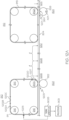
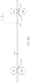
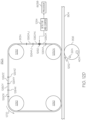
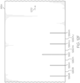
- Figs. 12D , 12E and 12F illustrate an alternative wet felt station 912A with a wet felt 913A traveling around four rollers 1250 in a direction shown by arrow 1270.
- attributes of the felt 913A are used to determine tracking segments.
- the rotating felt 913A could include multiple, evenly-spaced marks that could be detected (e.g., optically) and counted as each such mark passes a location of a sensor or detector 1254.
- the detector 1254 can also include counter circuitry that communicates with a processor 903B and counts or tracks the events that occur.
- the marks could also be metallic wires or threads that are detectable with magnets or similar switches. The marks would function so as to separate the felt 913A (or the felt 911.) into different segments and a counter, or similar circuitry, would increment a count each time a mark was detected (e.g., an event) so that any collected data could be associated with one of the segments of the felt 913A. It is also contemplated that the marks may not be evenly spaced.
- the felt 913A may have 37 physical circumferential segments 1260A - 1260AK, of which, segments 1260A, 1260X, 1260Y, 1260Z, 1260 AJ and 1260AK are explicitly referenced in Fig. 12D .
- segments 1260A, 1260X, 1260Y, 1260Z, 1260 AJ and 1260AK are explicitly referenced in Fig. 12D .
- Separating each physical circumferential segment 1260 is a mark 1264 (e.g., marks 1264A, 1264X, 1264Y, 1264Z, 1264AJ are explicitly shown in Fig. 12D ).
- a reference mark 1262 could be distinctive from all the other marks 1264A - 1264AJ such that when the detector 1254.
- the counter circuitry 1254 resets and starts counting from an initial value, or "starting count,” (e.g., "0" or "1").
- starting count e.g., "0" or "1”
- the reference marks can all be unique and specifically mark certain positions on the felt.
- one of the rollers 1250 forms a nip 1252 with a sensing roll 926 that has a wireless device 40A for communicating with the processor 903B and an array of sensors 26A (e.g., 14 sensors) spaced axially along the sensing roll 926.
- sensors 26A e.g., 14 sensors
- the sensor 26A in one of the axially positions on the sensing roll 926 enters a region of the nip 1252 and senses a pressure reading
- that pressure value can be count synchronized with the rotation of the wet felt 913A by associating the sensor readings at that axial position with a current value of the counter 1254.
- the pressure value can also be considered to be time synchronized with the rotation of the felt 913A by associating the sensor reading at that axial position with a current value of the counter 1254.
- a starting reference signal can be generated that is associated with each rotation of the wet felt 913A.
- the starting reference signal may, for example, be resetting the value of the counter 1254 to a starting count such as, for example, "1".
- each count (e.g., "1", “2”, ... “37") can be associated with one of a plurality of count-based tracking segments wherein each count-based tracking segment is associated with a different physical circumferential segment 1260A - 1260AK of the wet felt 913A in one embodiment of the present invention.
- each count-based tracking segment is equal to the count or value of the counter. If the tick marks 1264 are evenly spaced, then the count-based tracking segments can correspond to time-based tracking segments of the period of rotation of the wet felt 913A or correspond to physical circumferential segments of the wet felt 913A.
- the wet felt 913A travels along with the web of material 904 through the nip 1252 formed with the sensing roll 926.
- a particular value of the detector/counter 1254 when a corresponding one particular physical circumferential segment (e.g., 1260A - 1260AK) of the wet felt 913 is in the region of the nip 1252 is associated with one of the plurality of count-based tracking segments.
- each count-based tracking segment corresponds to a different physical circumferential segment 1260A-1260AK of the wet felt 913A.
- the processor 903B associates that sensor reading with a current value of the counter 1254, associates the count generated by the counter 1254 with a corresponding count-based tracking segment and stores that sensor reading with a tracking segment corresponding to the count generated when sensor reading occurred.
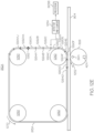
- Fig. 12E illustrates the felt 913A of Fig. 12D after it has rotated to a different position and the sensor 26A generates a sensed pressure signal of the region of the nip 1252.
- the felt 913A has rotated an amount such that the tick marks 1262, 1264A, 1264B and 1264C have been detected and counted by the detector/counter 1254.
- an example count for the position of the felt 913A of Fig. 12E would be "4" when the sensor reading from sensor 26A is captured.
- This count value would correspond to one of the 37 (for example) tracking segments that each of the sensor readings will be associated with and each such tracking segment (or count value) would correspond to a different physical circumferential segment 1260A-1260AK of the wet felt 913A.
- the physical circumferential segment 1260F of the felt 913A is in the region of the nip 1252. Accordingly, a plurality of sensed pressure readings from the region of the nip 1252 associated with the tracking segment, or count reading, of "4" could all be associated with the physical circumferential segment 1260F of the felt 913A.
- the tracking segment, or count value when the felt rotates such that the tick mark 1264D is detected and counted, the tracking segment, or count value, will be "5" and will correspond to pressure readings sensed when physical circumferential segment 1260G is in the region of the nip 1252.
- tick marks In addition to being on a surface of one of the felts, the tick marks, or similar marks or openings, could be included on a disk coupled to a rotating shaft or on the shaft itself associated with one of the multiple rotating components that help drive the felt around its continuous loop. Such an arrangement may be used to provide a rotary encoder beneficial in identifying respective tracking segments of a felt or other continuous band.
- a shaft encoder of this type could provide a value that corresponds to a count of the number of tick marks or openings that were detected between when a most recent starting reference was generated and when a sensor (e.g., 26A) enters a region of a nip where a pressure reading, or other reading, is being sensed. Accordingly, one of a plurality of tracking segments associated with the continuous band can be identified based on this value.
Landscapes
- Chemical & Material Sciences (AREA)
- Analytical Chemistry (AREA)
- Physics & Mathematics (AREA)
- General Physics & Mathematics (AREA)
- Paper (AREA)
- Control Of Conveyors (AREA)
- Length Measuring Devices With Unspecified Measuring Means (AREA)
- Controlling Rewinding, Feeding, Winding, Or Abnormalities Of Webs (AREA)
- Treatment Of Fiber Materials (AREA)
Claims (8)
- System, das einer Erfassungswalze (10, 918, 926) und einer Gegenwalze (11, 940A, 942A) zum Erfassen von Sensorsignalen zugeordnet ist, das Folgendes umfasst:die Erfassungswalze und die Gegenwalze, die derart relativ zueinander angeordnet sind, dass ein Spalt (12, 212A, 1201) dazwischen erzeugt wird, wobei sich eine Materialbahn von einer Stromaufwärtsrichtung zu einer Stromabwärtsrichtung durch den Spalt fortbewegt und ein ununterbrochenes Band, das derart angeordnet ist, dass es sich in einer Schleifenstruktur rundum bewegt, zumindest einen Bereich der Materialbahn am Spalt oder stromaufwärts des Spalts berührt;mehrere Sensoren (26, 26A, 1302A), die an axial beabstandeten Orten der Erfassungswalze angeordnet sind, wobei jeder Sensor während jeder Umdrehung der Erfassungswalze in einen Bereich des Spalts eintritt, um ein jeweiliges Sensorsignal zu erzeugen;eine Struktur (900A, 900B, 900C) zum Erzeugen einer periodisch auftretenden Startreferenz, die jeder Umdrehung des ununterbrochenen Bands um die Schleifenstruktur zugeordnet ist; undeinen Prozessor (903, 903A), um die periodisch auftretende Startreferenz und das jeweilige Sensorsignal, das durch jeden Sensor erzeugt wird, zu empfangen, und wobei der Prozessor nach dem Empfangen des jeweiligen Sensorsignals arbeitet zum:Bestimmen eines bestimmten der mehreren Sensoren, der das jeweilige Sensorsignal erzeugte, undauf der Grundlage einer Zeitspanne, die zwischen der Zeit, zu der das jeweilige Sensorsignal erzeugt wurde, und einer letzten Startreferenz verstrichen ist, Identifizieren eines von mehreren Nachverfolgungssegmenten, die dem ununterbrochenen Band zugeordnet sind, wobei jedes der mehreren Nachverfolgungssegmente jeweils einer unterschiedlichen Spanne der verstrichenen Zeit zugeordnet ist, undSpeichern des jeweiligen Sensorsignals, derart, dass das jeweilige Sensorsignal dem identifizierten einen Nachverfolgungssegment zugeordnet wird.
- System nach Anspruch 1, wobei:die Startreferenz eine Zeitreferenz umfasst;der Wert, der zwischen der Zeit, zu der das jeweilige Sensorsignal erzeugt wurde, und der letzten Startreferenz auftritt, aus einer Zeitspanne berechnet wird, die zwischen der Zeit, zu der das jeweilige Sensorsignal erzeugt wurde, und einer letzten Zeitreferenz verstrichen ist; undjedes der mehreren Nachverfolgungssegmente jeweils einer unterschiedlichen Spanne der verstrichenen Zeit zugeordnet ist;vorzugsweise,wobei das ununterbrochene Band ein Pressfilz (911, 913)
oderein Drahtgewebe (906) umfasst;und/oder vorzugsweise,wobei sich das ununterbrochene Band durch den Spalt bewegt,und/oder vorzugsweise,wobei das empfangene Sensorsignal einen Druckwert umfasst. - System nach Anspruch 1, wobei die mehreren Nachverfolgungssegmente, die dem ununterbrochenen Band zugeordnet sind und mehrere Umfangssegmente auf dem ununterbrochenen Band umfassen,mehrere Zeitsegmente einer Umdrehungsperiode des ununterbrochenen Bands umfassen;
oderwobei das ununterbrochene Band mehrere detektierbare Markierungen umfasst, die zumindest entlang eines Abschnitts einer Oberfläche des ununterbrochenen Bands gleichmäßig beabstandet sind. - System nach Anspruch 1, wobeidas ununterbrochene Band mehrere detektierbare Markierungen zumindest entlang eines Abschnitts einer Oberfläche des ununterbrochenen Bands umfasst, wobei eine ausgeprägte Markierung der mehreren detektierbaren Markierungen anders als alle anderen Markierungen ist, vorzugsweise,wobei die Struktur zum Erzeugen der Startreferenz Folgendes umfasst:einen Detektor in räumlicher Nähe zur Oberfläche des ununterbrochenen Bands zum Detektieren jeder der mehreren detektierbaren Markierungen, die sich am Detektor vorbeibewegen, wobei jede der mehreren detektierbaren Markierungen, die sich am Detektor vorbeibewegen, ein jeweiliges Ereignis definiert; undeinen Signalgenerator in Kommunikation mit dem Detektor zum Erzeugen der Startreferenz jedes Mal, wenn die eine ausgeprägte Markierung detektiert wird;stärker bevorzugt,wobei:die Startreferenz eine Startzählung umfasst;der Wert, der zwischen der Zeit, zu der das jeweilige Sensorsignal erzeugt wurde, und der letzten Startreferenz auftritt, aus einer Anzahl von Ereignissen berechnet wird, die zwischen der Zeit, zu der das jeweilige Sensorsignal erzeugt wurde, und der Startzählung aufgetreten sind; undjedes der mehreren Nachverfolgungssegmente jeweils einer unterschiedlichen Anzahl von Ereignissen zugeordnet ist; und/oder nochmals stärker bevorzugt,wobei das Erzeugen der Startreferenz das Zurücksetzen eines Zählers auf die Startzählung umfasst;und/oder nochmals stärker bevorzugt,wobei das ununterbrochene Band ein Pressfilz
oderein Drahtgewebe umfasst;und/oder nochmals stärker bevorzugt,wobei sich das ununterbrochene Band durch den Spalt bewegt;oder nochmals stärker bevorzugt,wobei sich das ununterbrochene Band nicht durch den Spalt bewegt und die Materialbahn stromaufwärts des Spalts berührt;und/oder nochmals stärker bevorzugt,wobei das empfangene Sensorsignal einen Druckwert umfasst;oder nochmals stärker bevorzugt,wobei die mehreren Nachverfolgungssegmente, die dem ununterbrochenen Band zugeordnet sind, mehrere Umfangssegmente auf dem ununterbrochenen Band umfassen. - Verfahren, das einer Erfassungswalze (10, 918, 926) und einer Gegenwalze (11, 940A, 942A) zum Erfassen von Sensorsignalen zugeordnet ist, das Folgendes umfasst:Erzeugen eines jeweiligen Sensorsignals von jedem von mehreren Sensoren (26, 26A, 1302A), die an axial beabstandeten Orten der Erfassungswalze angeordnet sind, wobei jedes jeweilige Sensorsignal erzeugt wird, wenn jeder Sensor während jeder Umdrehung der Erfassungswalze in einen Bereich eines Spalts (12, 212A, 1201) zwischen der Erfassungswalze und der Gegenwalze eintritt; wobei die Erfassungswalze und die Gegenwalze derart relativ zueinander angeordnet sind, dass der Spalt dazwischen erzeugt wird, wobei sich eine Materialbahn von einer Stromaufwärtsrichtung zu einer Stromabwärtsrichtung durch den Spalt fortbewegt und ein ununterbrochenes Band, das derart angeordnet ist, dass es sich in einer Schleifenstruktur rundum bewegt, zumindest einen Bereich der Materialbahn am Spalt oder stromaufwärts des Spalts berührt;Erzeugen einer periodisch auftretenden Startreferenz, die jeder Umdrehung des ununterbrochenen Bands um die Schleifenstruktur zugeordnet ist; undEmpfangen des jeweiligen Sensorsignals, das von jedem Sensor erzeugt wird, und nach Empfangen des jeweiligen Sensorsignals:Bestimmen eines bestimmten der mehreren Sensoren, der das jeweilige Sensorsignal erzeugte,auf der Grundlage einer Zeitspanne, die zwischen der Zeit, zu der das jeweilige Sensorsignal erzeugt wurde, und einer letzten Startreferenz verstrichen ist, Identifizieren eines von mehreren Nachverfolgungssegmenten, die dem ununterbrochenen Band zugeordnet sind, wobei jedes der mehreren Nachverfolgungssegmente jeweils einer unterschiedlichen Spanne der verstrichenen Zeit zugeordnet ist, undSpeichern des jeweiligen Sensorsignals, derart, dass das jeweilige Sensorsignal dem identifizierten einen Nachverfolgungssegment zugeordnet wird.
- Verfahren nach Anspruch 5, wobei:die Startreferenz eine Zeitreferenz umfasst;der Wert, der zwischen der Zeit, zu der das jeweilige Sensorsignal erzeugt wurde, und der letzten Startreferenz auftritt, aus einer Zeitspanne berechnet wird, die zwischen der Zeit, zu der das jeweilige Sensorsignal erzeugt wurde, und einer letzten Zeitreferenz verstrichen ist; undjedes der mehreren Nachverfolgungssegmente jeweils einer unterschiedlichen Spanne der verstrichenen Zeit zugeordnet ist;vorzugsweise,wobei das ununterbrochene Band ein Pressfilz (911, 913);
oderein Drahtgewebe (906) umfasst;und/oder vorzugsweise,wobei sich das ununterbrochene Band durch den Spalt bewegt. - Verfahren nach Anspruch 5, wobei die mehreren Nachverfolgungssegmente, die dem ununterbrochenen Band zugeordnet sind und mehrere Umfangssegmente auf dem ununterbrochenen Band umfassen,mehrere Zeitsegmente einer Umdrehungsperiode des ununterbrochenen Bands umfassen;
oderwobei:
das ununterbrochene Band mehrere detektierbare Markierungen umfasst, die zumindest entlang eines Abschnitts einer Oberfläche des ununterbrochenen Bands gleichmäßig beabstandet sind. - Verfahren nach Anspruch 5, wobeidas ununterbrochene Band mehrere detektierbare Markierungen zumindest entlang eines Abschnitts einer Oberfläche des ununterbrochenen Bands umfasst, wobei eine ausgeprägte Markierung der mehreren detektierbaren Markierungen anders als alle anderen Markierungen ist; vorzugsweise,Folgendes umfasst:Detektieren jeder der mehreren detektierbaren Markierungen, die sich am Detektor vorbeibewegen, als ein jeweiliges Ereignis mit einem Detektor in räumlicher Nähe zur Oberfläche des ununterbrochenen Bands; undErzeugen einer periodisch auftretenden Startreferenz, die jeder Umdrehung des ununterbrochenen Bands um die Schleifenstruktur zugeordnet ist, wobei die Startreferenz eine Startzählung istund jedes Mal erzeugt wird, wenn die eine ausgeprägte Markierung detektiert wird;stärker bevorzugt,wobei:die Startreferenz eine Startzählung umfasst;der Wert, der zwischen der Zeit, zu der das jeweilige Sensorsignal erzeugt wurde, und der letzten Startreferenz auftritt, aus einer Anzahl von Ereignissen berechnet wird, die zwischen der Zeit, zu der das jeweilige Sensorsignal erzeugt wurde, und der Startzählung aufgetreten sind; undjedes der mehreren Nachverfolgungssegmente jeweils einer unterschiedlichen Anzahl von Ereignissen zugeordnet ist; nochmals stärker bevorzugt,wobei das Erzeugen der Startreferenz das Zurücksetzen eines Zählers auf die Startzählung umfasst;oder nochmals stärker bevorzugt,wobei das ununterbrochene Band ein Pressfilz;
oderein Drahtgewebe umfasst;oder nochmals stärker bevorzugt,wobei sich das ununterbrochene Band durch den Spalt bewegt;oder nochmals stärker bevorzugt,wobei sich das ununterbrochene Band nicht durch den Spalt bewegt und die Materialbahn stromaufwärts des Spalts berührt;oder nochmals stärker bevorzugt,wobei die mehreren Nachverfolgungssegmente, die dem ununterbrochenen Band zugeordnet sind, mehrere Umfangssegmente auf dem ununterbrochenen Band umfassen.
Applications Claiming Priority (2)
| Application Number | Priority Date | Filing Date | Title |
|---|---|---|---|
| US14/735,892 US9696226B2 (en) | 2015-06-10 | 2015-06-10 | Count-based monitoring machine wires and felts |
| PCT/US2016/036592 WO2016201042A1 (en) | 2015-06-10 | 2016-06-09 | System and method for monitoring a band |
Publications (3)
| Publication Number | Publication Date |
|---|---|
| EP3307946A1 EP3307946A1 (de) | 2018-04-18 |
| EP3307946B1 true EP3307946B1 (de) | 2025-03-26 |
| EP3307946C0 EP3307946C0 (de) | 2025-03-26 |
Family
ID=56292894
Family Applications (1)
| Application Number | Title | Priority Date | Filing Date |
|---|---|---|---|
| EP16733770.8A Active EP3307946B1 (de) | 2015-06-10 | 2016-06-09 | System und verfahren zur überwachung eines bandes |
Country Status (10)
| Country | Link |
|---|---|
| US (1) | US9696226B2 (de) |
| EP (1) | EP3307946B1 (de) |
| CN (2) | CN107690497B (de) |
| BR (1) | BR112017024900B1 (de) |
| CA (1) | CA2980784C (de) |
| ES (1) | ES3030169T3 (de) |
| MY (1) | MY192550A (de) |
| PL (1) | PL3307946T3 (de) |
| RU (1) | RU2668192C1 (de) |
| WO (1) | WO2016201042A1 (de) |
Families Citing this family (11)
| Publication number | Priority date | Publication date | Assignee | Title |
|---|---|---|---|---|
| US9540769B2 (en) | 2013-03-11 | 2017-01-10 | International Paper Company | Method and apparatus for measuring and removing rotational variability from a nip pressure profile of a covered roll of a nip press |
| US9804044B2 (en) | 2014-05-02 | 2017-10-31 | International Paper Company | Method and system associated with a sensing roll and a mating roll for collecting data including first and second sensor arrays |
| US9797788B2 (en) | 2014-05-02 | 2017-10-24 | International Paper Company | Method and system associated with a sensing roll including pluralities of sensors and a mating roll for collecting roll data |
| US10378980B2 (en) | 2014-05-02 | 2019-08-13 | International Paper Company | Method and system associated with a sensing roll and a mating roll for collecting roll data |
| US10370795B2 (en) | 2015-06-10 | 2019-08-06 | International Paper Company | Monitoring applicator rods and applicator rod nips |
| US9696226B2 (en) * | 2015-06-10 | 2017-07-04 | International Paper Company | Count-based monitoring machine wires and felts |
| US9863827B2 (en) * | 2015-06-10 | 2018-01-09 | International Paper Company | Monitoring machine wires and felts |
| US9677225B2 (en) | 2015-06-10 | 2017-06-13 | International Paper Company | Monitoring applicator rods |
| US9816232B2 (en) | 2015-06-10 | 2017-11-14 | International Paper Company | Monitoring upstream machine wires and felts |
| EP4293157A3 (de) | 2017-09-18 | 2024-06-05 | International Paper Company | Verfahren zur steuerung eines faserfraktionierungssystems |
| EP3892967B1 (de) * | 2020-04-06 | 2022-08-03 | FMS Force Measuring Systems AG | Kraftmesseinrichtung zur erfassung von bahnzügen einer laufenden materialbahn |
Family Cites Families (112)
| Publication number | Priority date | Publication date | Assignee | Title |
|---|---|---|---|---|
| US757221A (en) | 1900-03-30 | 1904-04-12 | Frank W Page | Smelting-furnace. |
| US2300909A (en) | 1939-04-14 | 1942-11-03 | Arthur E Broughton | Reciprocating shower |
| US3622448A (en) | 1968-02-16 | 1971-11-23 | Industrial Nucleonics Corp | System and method of process control, particularly papermaking processes in response to fraction defective measurements |
| US3673865A (en) | 1971-04-21 | 1972-07-04 | Westvaco Corp | Method and apparatus for orthogonal variables |
| US3840302A (en) | 1971-06-01 | 1974-10-08 | D Brunton | Oscilloscope presentation of sheet profile from a scanning gage |
| JPS5418145B1 (de) | 1971-06-08 | 1979-07-05 | ||
| US3936665A (en) | 1972-06-12 | 1976-02-03 | Industrial Nucleonics Corporation | Sheet material characteristic measuring, monitoring and controlling method and apparatus using data profile generated and evaluated by computer means |
| US3863453A (en) | 1974-02-19 | 1975-02-04 | Dominion Eng Works Ltd | Oscillator system for paper machine |
| CA1014638A (en) | 1974-04-16 | 1977-07-26 | Domtar Limited | Measuring the surface roughness of a moving sheet material |
| GB1507987A (en) | 1974-07-15 | 1978-04-19 | British Steel Corp | Mill stand roll parameter monitor |
| US3989085A (en) | 1975-06-02 | 1976-11-02 | Westvaco Corporation | Method and apparatus for leveling the cross-direction profile of stock slurry on a papermachine |
| US4092068A (en) | 1976-05-05 | 1978-05-30 | Domtar Inc. | Surface sensor |
| US4152202A (en) | 1976-08-02 | 1979-05-01 | Westvaco Corporation | Method and apparatus for leveling the cross-direction profile of stock slurry on a paper machine |
| DE2837913C2 (de) | 1978-08-31 | 1982-10-21 | ER-WE-PA Maschinenfabrik und Eisengießerei GmbH, 4006 Erkrath | Walze mit steuerbarer Durchbiegung, insbesondere für Maschinen zur Erzeugung und Verarbeitung von Bahnen aus Papier oder Kunststoff |
| DE3117398A1 (de) | 1981-05-02 | 1982-11-18 | Escher Wyss AG, Zürich | "anordnung mit einer durchbiegungseinstellwalze und zugehoerigem regler" |
| US4423636A (en) | 1981-12-08 | 1984-01-03 | Bethlehem Steel Corporation | Articulated test probe mechanism with fluid bearing in test roll gap |
| US4495587A (en) | 1981-12-08 | 1985-01-22 | Bethlehem Steel Corporation | Automatic nondestructive roll defect inspection system |
| US4524546A (en) | 1983-06-06 | 1985-06-25 | Armco Inc | Roll profile gauge |
| SE463269B (sv) | 1984-04-11 | 1990-10-29 | Sensodec Oy | Foerfarande och anordning foer att lokalisera fel i funktionen hos en pappersmaskins maskindelar |
| DE3516535A1 (de) | 1985-05-08 | 1986-11-13 | Kleinewefers Gmbh | Walzenaggregat mit durchbiegungssteuerbarer und temperierbarer walze |
| US4879471A (en) | 1987-03-25 | 1989-11-07 | Measurex Corporation | Rapid-scanning infrared sensor |
| US4898012A (en) | 1988-04-22 | 1990-02-06 | United Engineering, Inc. | Roll bite gauge and profile measurement system for rolling mills |
| US4903528A (en) | 1988-09-26 | 1990-02-27 | Measurex Corporation | System and process for detecting properties of travelling sheets in the cross direction |
| US4947684A (en) | 1989-01-27 | 1990-08-14 | Measurex Corporation | System and process for detecting properties of travelling sheets in the machine direction |
| US4921574A (en) | 1989-01-27 | 1990-05-01 | Measurex Corporation | Process for controlling properties of travelling sheets with scan widths less than the sheet width |
| US5022966A (en) | 1989-01-27 | 1991-06-11 | Measurex Corporation | Process for controlling properties of travelling sheets |
| US5121332A (en) | 1989-03-31 | 1992-06-09 | Measurex Corporation | Control system for sheetmaking |
| US5048353A (en) | 1990-03-01 | 1991-09-17 | Beloit Corporation | Method and apparatus for roll profile measurement |
| US5122963A (en) | 1990-03-07 | 1992-06-16 | Process Automation Business, Inc. | Actuation cell response and mapping determinations for web forming machines |
| US5125746A (en) | 1990-06-07 | 1992-06-30 | Harold Lipshitz | Surface topography measurement apparatus and method |
| FI86771C (fi) * | 1991-10-14 | 1992-10-12 | Valmet Paper Machinery Inc | Foerfarande och anordning foer maetning av nypkraften och/eller -trycket av ett nyp som bildas av en roterande vals eller ett band som anvaends vid framstaellning av papper |
| FI89308C (fi) * | 1992-09-16 | 1993-09-10 | Valmet Paper Machinery Inc | Foerfarande och anordning foer maetning av nypkraften och/eller -trycket av ett nyp som bildas av en roterande vals eller ett band som anvaends vid framstaellning av papper |
| US5400258A (en) | 1993-09-03 | 1995-03-21 | Measurex Corporation | Automatic cross-directional control zone alignment for sheetmaking systems |
| US5563809A (en) | 1994-04-06 | 1996-10-08 | Abb Industrial Systems, Inc. | Measurement/control of sheet material using at least one sensor array |
| GB9411908D0 (en) | 1994-06-14 | 1994-08-03 | John Heyer Paper Ltd | Web monitoring for paper machines |
| US5592875A (en) | 1994-09-16 | 1997-01-14 | Stowe Woodward Licensco, Inc. | Roll having means for determining pressure distribution |
| US5562027A (en) | 1995-02-16 | 1996-10-08 | Stowe Woodward Licensco, Inc. | Dynamic nip pressure and temperature sensing system |
| US5743177A (en) | 1996-02-29 | 1998-04-28 | Union Camp Corporation | Enhanced cross-directional caliper control system |
| US5725737A (en) | 1996-09-18 | 1998-03-10 | Pulp And Paper Research Institute Of Canada | Apparatus for the detection of holes and plugged spots |
| US5960374A (en) | 1997-02-14 | 1999-09-28 | International Paper Company | System for time synchronous monitoring of product quality variable |
| DE19742755A1 (de) | 1997-09-27 | 1999-04-01 | Roehm Gmbh | Verfahren zum Erreichen einer stabilen Regelung des Wulstprofils bei der Extrusion von Platten und Folien aus thermoplastischem Kunststoff |
| US6336078B1 (en) | 1997-09-30 | 2002-01-01 | Canon Kabushiki Kaisha | Quality management of components |
| CA2318196C (en) | 1998-02-10 | 2008-04-22 | Abb Industrial Systems, Inc. | Method for extracting and classifying sheet variation patterns from two-dimensional sheet measurements |
| US6568285B1 (en) | 1998-02-19 | 2003-05-27 | Stowe Woodward Llc | Nip width sensing system and method |
| US6356846B1 (en) | 1998-10-13 | 2002-03-12 | Institute Of Paper Science And Technology, Inc. | System and method of reducing motion-induced noise in the optical detection of an ultrasound signal in a moving body of material |
| US6370961B1 (en) | 1999-01-29 | 2002-04-16 | Constantin M. Trantzas | Nipped roller impression sensor system |
| US6519552B1 (en) | 1999-09-15 | 2003-02-11 | Xerox Corporation | Systems and methods for a hybrid diagnostic approach of real time diagnosis of electronic systems |
| US6934028B2 (en) | 2000-01-20 | 2005-08-23 | Webview, Inc. | Certification and verification management system and method for a web inspection apparatus |
| US6567720B1 (en) | 2001-04-20 | 2003-05-20 | Kerry D. Figiel | Method and apparatus for time synchronized measurement correction of multidimensional periodic effects on a moving web |
| FI114741B (fi) | 2001-05-11 | 2004-12-15 | Metso Automation Oy | Lämpökuvaukseen perustuva laadun- ja kunnonvalvontamenetelmä |
| FI115163B (fi) | 2001-11-29 | 2005-03-15 | Metso Automation Oy | Spektrierottelevaan mittaukseen perustuva laadun- ja kunnonvalvonta |
| US6805899B2 (en) | 2002-01-30 | 2004-10-19 | Honeywell International Inc. | Multi-measurement/sensor coating consolidation detection method and system |
| JP2003241535A (ja) * | 2002-02-20 | 2003-08-29 | Ricoh Co Ltd | ベルト移動装置および該装置を備えた画像形成装置 |
| DE10216069A1 (de) | 2002-04-11 | 2003-10-23 | Hauni Maschinenbau Ag | Verfahren und Vorrichtung zum Einwirken auf Artikel der tabakverarbeitenden Industrie |
| DE10312464A1 (de) | 2003-03-20 | 2004-09-30 | Fraunhofer-Gesellschaft zur Förderung der angewandten Forschung e.V. | Zusammensetzung zur Herstellung eines Duroplasten mit thermochromen Eigenschaften |
| US20040033377A1 (en) | 2002-06-10 | 2004-02-19 | Koenig Michael F. | Waterfast dye fixative compositions for ink jet recording sheets |
| US7608338B2 (en) | 2002-06-13 | 2009-10-27 | International Paper Company | High brightness coating compositions and related products |
| US7018708B2 (en) | 2002-08-22 | 2006-03-28 | International Paper Company | Gloss-coated paper with enhanced runnability and print quality |
| DE10249385A1 (de) | 2002-10-23 | 2004-05-06 | Voith Paper Patent Gmbh | Verfahren und Einrichtung zur Überwachung des Zustandes einer Bespannung |
| SE0300127D0 (sv) * | 2003-01-17 | 2003-01-17 | Imego Ab | Indicator arrangement |
| CN1795307B (zh) | 2003-04-07 | 2010-09-08 | 国际纸业公司 | 用于液体电子照相印刷的纸张及其制备方法 |
| DE10321865B4 (de) | 2003-05-14 | 2013-06-27 | Betriebsforschungsinstitut VDEh - Institut für angewandte Forschung GmbH | Messvorrichtung für ein längsbewegtes Band und Messverfahren für Prozessparameter einer Bandförderung |
| US7185537B2 (en) * | 2003-06-04 | 2007-03-06 | Metso Paper, Inc. | Nip and loading analysis system |
| US6950777B1 (en) | 2003-07-29 | 2005-09-27 | Voith Paper Inc. | Method and system for assessing pulp and paper mill performance |
| US7608166B2 (en) | 2003-09-17 | 2009-10-27 | International Paper Company | Papers having borate-based complexing and method of making same |
| DE10343418A1 (de) * | 2003-09-19 | 2005-04-21 | Voith Paper Patent Gmbh | Vorrichtung und Verfahren zur Beurteilung der Beschaffenheit mindestens eines umlaufenden Bandes |
| DE102004045418A1 (de) | 2004-03-16 | 2005-10-06 | Waldrich Siegen Werkzeugmaschinen Gmbh | Verfahren und Vorrichtung zum Schleifen einer Walze |
| BRPI0511017A (pt) | 2004-05-14 | 2007-11-27 | Stowe Woodward Llc | sistema e método para determinar caracterìsticas de dois rolos configurados em uma prensa de passe, e, tira para uso em uma prensa de passe entre dois rolos |
| US20050261115A1 (en) | 2004-05-14 | 2005-11-24 | Myers Bigel Sibley & Sajovec, P.A. | Industrial roll with piezoelectric sensors for detecting pressure |
| BRPI0510978A (pt) | 2004-05-14 | 2007-11-27 | Stowe Woodward Llc | sistema para medição de largura de espaço para um espaço presente entre dois rolos, e, método para determinar a largura de um espaço posicionado entre dois rolos |
| US7392715B2 (en) | 2004-10-29 | 2008-07-01 | Stowe Woodward Ag | Wireless sensors in roll covers |
| FI20055019L (fi) | 2005-01-17 | 2006-07-18 | Metso Paper Inc | Rainan kireysprofiilin mittausmenetelmä ja sitä soveltava tela |
| US7572214B2 (en) | 2005-05-04 | 2009-08-11 | Stowe Woodward L.L.C. | Suction roll with sensors for detecting operational parameters having apertures |
| US20070006644A1 (en) | 2005-07-06 | 2007-01-11 | Alcoa Inc. | Continuous web stress distribution measurement sensor |
| US8758886B2 (en) | 2005-10-14 | 2014-06-24 | International Paper Company | Recording sheet with improved image dry time |
| US7582188B2 (en) | 2005-10-14 | 2009-09-01 | Hewlett-Packard Development Company, L.P. | Composition and ink receiving system incorporating the composition |
| EP2290162B1 (de) | 2006-01-17 | 2017-05-03 | International Paper Company | Papiersubstrate mit hoher Oberflächenleimung und niedriger innerer Leimung sowie hoher Dimensionsstabilität |
| JP4940937B2 (ja) | 2006-02-28 | 2012-05-30 | 日本精工株式会社 | 回転機械の状態量測定装置 |
| CN101595261B (zh) | 2006-12-11 | 2014-04-09 | 国际纸业公司 | 纸张施胶组合物、施胶纸张和对纸张进行施胶的方法 |
| FI20075472L (fi) | 2007-06-20 | 2008-12-21 | Metso Paper Inc | Menetelmä paperikoneen tai vastaavan puristinhuovan kunnon/tilan arvioinnissa |
| JP4941258B2 (ja) | 2007-11-30 | 2012-05-30 | ブラザー工業株式会社 | シート端検出装置、及びこれを備える画像記録装置 |
| WO2009092761A2 (en) | 2008-01-24 | 2009-07-30 | Metso Paper, Inc. | Papermaking coating station with pressure-sensitive film roll |
| ES2390619T3 (es) | 2008-03-31 | 2012-11-14 | International Paper Company | Hoja de impresión con calidad mejorada de impresión a niveles bajos de aditivos |
| WO2009146416A1 (en) | 2008-05-29 | 2009-12-03 | International Paper Company | Fast dry coated inkjet paper |
| BRPI0822792B1 (pt) * | 2008-09-23 | 2019-04-16 | Voith Patent Gmbh | Rolo industrial com sistema sensor de cobertura do rolo ótico |
| CN102224458B (zh) | 2008-10-15 | 2013-04-24 | 国际纸业公司 | 组合物、制备方法以及施加和曝光光成像纸张的方法 |
| CN102224460B (zh) | 2008-10-15 | 2015-01-21 | 国际纸业公司 | 成像颗粒组合物、纸张和方法以及使用双波长光对纸张成像的方法 |
| US9097595B2 (en) | 2008-11-14 | 2015-08-04 | Stowe Woodward, L.L.C. | System and method for detecting and measuring vibration in an industrial roll |
| FI8397U1 (fi) | 2009-05-27 | 2009-08-14 | Metso Paper Inc | Laite kuiturainan valmistuksessa |
| US8236141B2 (en) | 2009-06-23 | 2012-08-07 | Stowe Woodward, L.L.C. | Industrial roll with sensors having conformable conductive sheets |
| US8574690B2 (en) | 2009-12-17 | 2013-11-05 | International Paper Company | Printable substrates with improved dry time and acceptable print density by using monovalent salts |
| US8652593B2 (en) | 2009-12-17 | 2014-02-18 | International Paper Company | Printable substrates with improved brightness from OBAs in presence of multivalent metal salts |
| FI20105205A0 (fi) | 2010-03-03 | 2010-03-03 | Pyynikki Engineering Oy | Menetelmä ja järjestelmä telan pinnan profiilin määrittämiseksi ja/tai hionnan ohjaamiseksi |
| US8608908B2 (en) | 2010-04-02 | 2013-12-17 | International Paper Company | Method and system using low fatty acid starches in paper sizing composition to inhibit deposition of multivalent fatty acid salts |
| US8440053B2 (en) | 2010-04-02 | 2013-05-14 | International Paper Company | Method and system using surfactants in paper sizing composition to inhibit deposition of multivalent fatty acid salts |
| WO2011139481A1 (en) | 2010-05-04 | 2011-11-10 | International Paper Company | Coated printed substrates resistant to acidic highlighters and printing solutions |
| US8475347B2 (en) * | 2010-06-04 | 2013-07-02 | Stowe Woodward Licensco, Llc | Industrial roll with multiple sensor arrays |
| WO2012012724A1 (en) | 2010-07-23 | 2012-01-26 | International Paper Company | Coated printable substrates providing higher print quality and resolution at lower ink usage |
| US8697203B2 (en) | 2010-11-16 | 2014-04-15 | International Paper Company | Paper sizing composition with salt of calcium (II) and organic acid, products made thereby, method of using, and method of making |
| JP5724345B2 (ja) | 2010-12-07 | 2015-05-27 | 富士ゼロックス株式会社 | シート測定装置および画像形成装置 |
| BR112013030716A2 (pt) | 2011-06-02 | 2019-09-24 | Stowe Woodward Licensco Llc | método e sistema para determinar a largura de um interstício formado por um rolo industrial e uma estrutura de associação, e, produto de programa de computador. |
| JP6016941B2 (ja) | 2012-01-17 | 2016-10-26 | ストウ・ウッドワード・ライセンスコ,リミテッド・ライアビリティ・カンパニー | 回転ロールの角位置を決定するシステムおよび方法 |
| JP5660066B2 (ja) | 2012-03-19 | 2015-01-28 | コニカミノルタ株式会社 | 画像形成装置 |
| US9540769B2 (en) | 2013-03-11 | 2017-01-10 | International Paper Company | Method and apparatus for measuring and removing rotational variability from a nip pressure profile of a covered roll of a nip press |
| CN105121743B (zh) | 2013-04-05 | 2017-09-26 | 福伊特专利有限公司 | 薄膜压榨 |
| US9745698B2 (en) * | 2013-04-30 | 2017-08-29 | Voith Patent Gmbh | Sensor roll |
| US9731489B2 (en) | 2013-05-29 | 2017-08-15 | H.B. Fuller Company | Material application system |
| US10378980B2 (en) | 2014-05-02 | 2019-08-13 | International Paper Company | Method and system associated with a sensing roll and a mating roll for collecting roll data |
| US9797788B2 (en) | 2014-05-02 | 2017-10-24 | International Paper Company | Method and system associated with a sensing roll including pluralities of sensors and a mating roll for collecting roll data |
| US9804044B2 (en) | 2014-05-02 | 2017-10-31 | International Paper Company | Method and system associated with a sensing roll and a mating roll for collecting data including first and second sensor arrays |
| US9863827B2 (en) * | 2015-06-10 | 2018-01-09 | International Paper Company | Monitoring machine wires and felts |
| US9696226B2 (en) * | 2015-06-10 | 2017-07-04 | International Paper Company | Count-based monitoring machine wires and felts |
-
2015
- 2015-06-10 US US14/735,892 patent/US9696226B2/en active Active
-
2016
- 2016-06-09 CN CN201680032747.2A patent/CN107690497B/zh active Active
- 2016-06-09 RU RU2017132489A patent/RU2668192C1/ru active
- 2016-06-09 MY MYPI2017703285A patent/MY192550A/en unknown
- 2016-06-09 EP EP16733770.8A patent/EP3307946B1/de active Active
- 2016-06-09 PL PL16733770.8T patent/PL3307946T3/pl unknown
- 2016-06-09 WO PCT/US2016/036592 patent/WO2016201042A1/en not_active Ceased
- 2016-06-09 CA CA2980784A patent/CA2980784C/en active Active
- 2016-06-09 ES ES16733770T patent/ES3030169T3/es active Active
- 2016-06-09 BR BR112017024900-6A patent/BR112017024900B1/pt active IP Right Grant
- 2016-06-09 CN CN201911226067.6A patent/CN111155352B/zh active Active
Also Published As
| Publication number | Publication date |
|---|---|
| BR112017024900A2 (pt) | 2018-07-31 |
| RU2668192C1 (ru) | 2018-09-26 |
| PL3307946T3 (pl) | 2025-06-16 |
| CN107690497B (zh) | 2020-01-07 |
| US20160363496A1 (en) | 2016-12-15 |
| CN111155352A (zh) | 2020-05-15 |
| WO2016201042A1 (en) | 2016-12-15 |
| BR112017024900B1 (pt) | 2022-07-19 |
| EP3307946A1 (de) | 2018-04-18 |
| CN111155352B (zh) | 2021-09-17 |
| CA2980784A1 (en) | 2016-12-15 |
| EP3307946C0 (de) | 2025-03-26 |
| ES3030169T3 (en) | 2025-06-26 |
| MY192550A (en) | 2022-08-28 |
| US9696226B2 (en) | 2017-07-04 |
| CA2980784C (en) | 2019-03-12 |
| CN107690497A (zh) | 2018-02-13 |
Similar Documents
| Publication | Publication Date | Title |
|---|---|---|
| EP3307946B1 (de) | System und verfahren zur überwachung eines bandes | |
| EP3307945B1 (de) | System und verfahren zur überwachung eines bandes | |
| EP3307947B1 (de) | Überwachung von vorgelagerten maschinendrähten und filzen | |
| US10378150B2 (en) | Monitoring applicator rods | |
| EP3828338B1 (de) | System und verfahren zur überwachung eines applikationsstabs | |
| WO2015168492A1 (en) | Method and system associated with a sensing roll including a first sensor array and a mating roll including a second sensor array for collecting roll data |
Legal Events
| Date | Code | Title | Description |
|---|---|---|---|
| STAA | Information on the status of an ep patent application or granted ep patent |
Free format text: STATUS: THE INTERNATIONAL PUBLICATION HAS BEEN MADE |
|
| PUAI | Public reference made under article 153(3) epc to a published international application that has entered the european phase |
Free format text: ORIGINAL CODE: 0009012 |
|
| STAA | Information on the status of an ep patent application or granted ep patent |
Free format text: STATUS: REQUEST FOR EXAMINATION WAS MADE |
|
| 17P | Request for examination filed |
Effective date: 20171127 |
|
| AK | Designated contracting states |
Kind code of ref document: A1 Designated state(s): AL AT BE BG CH CY CZ DE DK EE ES FI FR GB GR HR HU IE IS IT LI LT LU LV MC MK MT NL NO PL PT RO RS SE SI SK SM TR |
|
| AX | Request for extension of the european patent |
Extension state: BA ME |
|
| DAV | Request for validation of the european patent (deleted) | ||
| DAX | Request for extension of the european patent (deleted) | ||
| STAA | Information on the status of an ep patent application or granted ep patent |
Free format text: STATUS: EXAMINATION IS IN PROGRESS |
|
| 17Q | First examination report despatched |
Effective date: 20181015 |
|
| GRAP | Despatch of communication of intention to grant a patent |
Free format text: ORIGINAL CODE: EPIDOSNIGR1 |
|
| STAA | Information on the status of an ep patent application or granted ep patent |
Free format text: STATUS: GRANT OF PATENT IS INTENDED |
|
| INTG | Intention to grant announced |
Effective date: 20240708 |
|
| GRAJ | Information related to disapproval of communication of intention to grant by the applicant or resumption of examination proceedings by the epo deleted |
Free format text: ORIGINAL CODE: EPIDOSDIGR1 |
|
| STAA | Information on the status of an ep patent application or granted ep patent |
Free format text: STATUS: EXAMINATION IS IN PROGRESS |
|
| GRAP | Despatch of communication of intention to grant a patent |
Free format text: ORIGINAL CODE: EPIDOSNIGR1 |
|
| STAA | Information on the status of an ep patent application or granted ep patent |
Free format text: STATUS: GRANT OF PATENT IS INTENDED |
|
| INTC | Intention to grant announced (deleted) | ||
| RIC1 | Information provided on ipc code assigned before grant |
Ipc: D21F 3/00 20060101ALI20241029BHEP Ipc: D21F 3/08 20060101ALI20241029BHEP Ipc: D21G 9/00 20060101ALI20241029BHEP Ipc: G01L 5/00 20060101ALI20241029BHEP Ipc: D21F 1/00 20060101ALI20241029BHEP Ipc: D21F 7/08 20060101ALI20241029BHEP Ipc: D21F 3/02 20060101AFI20241029BHEP |
|
| INTG | Intention to grant announced |
Effective date: 20241108 |
|
| GRAS | Grant fee paid |
Free format text: ORIGINAL CODE: EPIDOSNIGR3 |
|
| GRAA | (expected) grant |
Free format text: ORIGINAL CODE: 0009210 |
|
| STAA | Information on the status of an ep patent application or granted ep patent |
Free format text: STATUS: THE PATENT HAS BEEN GRANTED |
|
| AK | Designated contracting states |
Kind code of ref document: B1 Designated state(s): AL AT BE BG CH CY CZ DE DK EE ES FI FR GB GR HR HU IE IS IT LI LT LU LV MC MK MT NL NO PL PT RO RS SE SI SK SM TR |
|
| REG | Reference to a national code |
Ref country code: GB Ref legal event code: FG4D |
|
| REG | Reference to a national code |
Ref country code: CH Ref legal event code: EP |
|
| REG | Reference to a national code |
Ref country code: DE Ref legal event code: R096 Ref document number: 602016091667 Country of ref document: DE |
|
| REG | Reference to a national code |
Ref country code: IE Ref legal event code: FG4D |
|
| U01 | Request for unitary effect filed |
Effective date: 20250407 |
|
| U07 | Unitary effect registered |
Designated state(s): AT BE BG DE DK EE FI FR IT LT LU LV MT NL PT RO SE SI Effective date: 20250414 |
|
| U20 | Renewal fee for the european patent with unitary effect paid |
Year of fee payment: 10 Effective date: 20250520 |
|
| REG | Reference to a national code |
Ref country code: ES Ref legal event code: FG2A Ref document number: 3030169 Country of ref document: ES Kind code of ref document: T3 Effective date: 20250626 |
|
| PG25 | Lapsed in a contracting state [announced via postgrant information from national office to epo] |
Ref country code: RS Free format text: LAPSE BECAUSE OF FAILURE TO SUBMIT A TRANSLATION OF THE DESCRIPTION OR TO PAY THE FEE WITHIN THE PRESCRIBED TIME-LIMIT Effective date: 20250626 |
|
| PGFP | Annual fee paid to national office [announced via postgrant information from national office to epo] |
Ref country code: PL Payment date: 20250513 Year of fee payment: 10 |
|
| PGFP | Annual fee paid to national office [announced via postgrant information from national office to epo] |
Ref country code: GB Payment date: 20250520 Year of fee payment: 10 |
|
| PG25 | Lapsed in a contracting state [announced via postgrant information from national office to epo] |
Ref country code: NO Free format text: LAPSE BECAUSE OF FAILURE TO SUBMIT A TRANSLATION OF THE DESCRIPTION OR TO PAY THE FEE WITHIN THE PRESCRIBED TIME-LIMIT Effective date: 20250626 |
|
| PG25 | Lapsed in a contracting state [announced via postgrant information from national office to epo] |
Ref country code: HR Free format text: LAPSE BECAUSE OF FAILURE TO SUBMIT A TRANSLATION OF THE DESCRIPTION OR TO PAY THE FEE WITHIN THE PRESCRIBED TIME-LIMIT Effective date: 20250326 |
|
| PG25 | Lapsed in a contracting state [announced via postgrant information from national office to epo] |
Ref country code: GR Free format text: LAPSE BECAUSE OF FAILURE TO SUBMIT A TRANSLATION OF THE DESCRIPTION OR TO PAY THE FEE WITHIN THE PRESCRIBED TIME-LIMIT Effective date: 20250627 |
|
| PG25 | Lapsed in a contracting state [announced via postgrant information from national office to epo] |
Ref country code: SM Free format text: LAPSE BECAUSE OF FAILURE TO SUBMIT A TRANSLATION OF THE DESCRIPTION OR TO PAY THE FEE WITHIN THE PRESCRIBED TIME-LIMIT Effective date: 20250326 |
|
| PGFP | Annual fee paid to national office [announced via postgrant information from national office to epo] |
Ref country code: ES Payment date: 20250701 Year of fee payment: 10 |
|
| PG25 | Lapsed in a contracting state [announced via postgrant information from national office to epo] |
Ref country code: SK Free format text: LAPSE BECAUSE OF FAILURE TO SUBMIT A TRANSLATION OF THE DESCRIPTION OR TO PAY THE FEE WITHIN THE PRESCRIBED TIME-LIMIT Effective date: 20250326 |
|
| PG25 | Lapsed in a contracting state [announced via postgrant information from national office to epo] |
Ref country code: IS Free format text: LAPSE BECAUSE OF FAILURE TO SUBMIT A TRANSLATION OF THE DESCRIPTION OR TO PAY THE FEE WITHIN THE PRESCRIBED TIME-LIMIT Effective date: 20250726 |
|
| PG25 | Lapsed in a contracting state [announced via postgrant information from national office to epo] |
Ref country code: CZ Free format text: LAPSE BECAUSE OF FAILURE TO SUBMIT A TRANSLATION OF THE DESCRIPTION OR TO PAY THE FEE WITHIN THE PRESCRIBED TIME-LIMIT Effective date: 20250326 |
|
| REG | Reference to a national code |
Ref country code: CH Ref legal event code: H13 Free format text: ST27 STATUS EVENT CODE: U-0-0-H10-H13 (AS PROVIDED BY THE NATIONAL OFFICE) Effective date: 20260127 |
|
| PG25 | Lapsed in a contracting state [announced via postgrant information from national office to epo] |
Ref country code: MC Free format text: LAPSE BECAUSE OF FAILURE TO SUBMIT A TRANSLATION OF THE DESCRIPTION OR TO PAY THE FEE WITHIN THE PRESCRIBED TIME-LIMIT Effective date: 20250326 |
|
| PLBE | No opposition filed within time limit |
Free format text: ORIGINAL CODE: 0009261 |
|
| STAA | Information on the status of an ep patent application or granted ep patent |
Free format text: STATUS: NO OPPOSITION FILED WITHIN TIME LIMIT |
|
| REG | Reference to a national code |
Ref country code: CH Ref legal event code: L10 Free format text: ST27 STATUS EVENT CODE: U-0-0-L10-L00 (AS PROVIDED BY THE NATIONAL OFFICE) Effective date: 20260211 |
|
| 26N | No opposition filed |
Effective date: 20260105 |
|
| PG25 | Lapsed in a contracting state [announced via postgrant information from national office to epo] |
Ref country code: IE Free format text: LAPSE BECAUSE OF NON-PAYMENT OF DUE FEES Effective date: 20250609 |
|
| PG25 | Lapsed in a contracting state [announced via postgrant information from national office to epo] |
Ref country code: CH Free format text: LAPSE BECAUSE OF NON-PAYMENT OF DUE FEES Effective date: 20250630 |