EP3307977B1 - Préforme de tube de mise sous vide - Google Patents
Préforme de tube de mise sous vide Download PDFInfo
- Publication number
- EP3307977B1 EP3307977B1 EP16806442.6A EP16806442A EP3307977B1 EP 3307977 B1 EP3307977 B1 EP 3307977B1 EP 16806442 A EP16806442 A EP 16806442A EP 3307977 B1 EP3307977 B1 EP 3307977B1
- Authority
- EP
- European Patent Office
- Prior art keywords
- preform
- glass
- tubular member
- pump
- out tube
- Prior art date
- Legal status (The legal status is an assumption and is not a legal conclusion. Google has not performed a legal analysis and makes no representation as to the accuracy of the status listed.)
- Not-in-force
Links
Images
Classifications
-
- E—FIXED CONSTRUCTIONS
- E06—DOORS, WINDOWS, SHUTTERS, OR ROLLER BLINDS IN GENERAL; LADDERS
- E06B—FIXED OR MOVABLE CLOSURES FOR OPENINGS IN BUILDINGS, VEHICLES, FENCES OR LIKE ENCLOSURES IN GENERAL, e.g. DOORS, WINDOWS, BLINDS, GATES
- E06B3/00—Window sashes, door leaves, or like elements for closing wall or like openings; Layout of fixed or moving closures, e.g. windows in wall or like openings; Features of rigidly-mounted outer frames relating to the mounting of wing frames
- E06B3/66—Units comprising two or more parallel glass or like panes permanently secured together
- E06B3/677—Evacuating or filling the gap between the panes ; Equilibration of inside and outside pressure; Preventing condensation in the gap between the panes; Cleaning the gap between the panes
- E06B3/6775—Evacuating or filling the gap during assembly
-
- C—CHEMISTRY; METALLURGY
- C03—GLASS; MINERAL OR SLAG WOOL
- C03B—MANUFACTURE, SHAPING, OR SUPPLEMENTARY PROCESSES
- C03B23/00—Re-forming shaped glass
- C03B23/20—Uniting glass pieces by fusing without substantial reshaping
-
- C—CHEMISTRY; METALLURGY
- C03—GLASS; MINERAL OR SLAG WOOL
- C03C—CHEMICAL COMPOSITION OF GLASSES, GLAZES OR VITREOUS ENAMELS; SURFACE TREATMENT OF GLASS; SURFACE TREATMENT OF FIBRES OR FILAMENTS MADE FROM GLASS, MINERALS OR SLAGS; JOINING GLASS TO GLASS OR OTHER MATERIALS
- C03C27/00—Joining pieces of glass to pieces of other inorganic material; Joining glass to glass other than by fusing
- C03C27/04—Joining glass to metal by means of an interlayer
- C03C27/042—Joining glass to metal by means of an interlayer consisting of a combination of materials selected from glass, glass-ceramic or ceramic material with metals, metal oxides or metal salts
-
- E—FIXED CONSTRUCTIONS
- E06—DOORS, WINDOWS, SHUTTERS, OR ROLLER BLINDS IN GENERAL; LADDERS
- E06B—FIXED OR MOVABLE CLOSURES FOR OPENINGS IN BUILDINGS, VEHICLES, FENCES OR LIKE ENCLOSURES IN GENERAL, e.g. DOORS, WINDOWS, BLINDS, GATES
- E06B3/00—Window sashes, door leaves, or like elements for closing wall or like openings; Layout of fixed or moving closures, e.g. windows in wall or like openings; Features of rigidly-mounted outer frames relating to the mounting of wing frames
- E06B3/66—Units comprising two or more parallel glass or like panes permanently secured together
- E06B3/6612—Evacuated glazing units
-
- Y—GENERAL TAGGING OF NEW TECHNOLOGICAL DEVELOPMENTS; GENERAL TAGGING OF CROSS-SECTIONAL TECHNOLOGIES SPANNING OVER SEVERAL SECTIONS OF THE IPC; TECHNICAL SUBJECTS COVERED BY FORMER USPC CROSS-REFERENCE ART COLLECTIONS [XRACs] AND DIGESTS
- Y02—TECHNOLOGIES OR APPLICATIONS FOR MITIGATION OR ADAPTATION AGAINST CLIMATE CHANGE
- Y02A—TECHNOLOGIES FOR ADAPTATION TO CLIMATE CHANGE
- Y02A30/00—Adapting or protecting infrastructure or their operation
- Y02A30/24—Structural elements or technologies for improving thermal insulation
- Y02A30/249—Glazing, e.g. vacuum glazing
-
- Y—GENERAL TAGGING OF NEW TECHNOLOGICAL DEVELOPMENTS; GENERAL TAGGING OF CROSS-SECTIONAL TECHNOLOGIES SPANNING OVER SEVERAL SECTIONS OF THE IPC; TECHNICAL SUBJECTS COVERED BY FORMER USPC CROSS-REFERENCE ART COLLECTIONS [XRACs] AND DIGESTS
- Y02—TECHNOLOGIES OR APPLICATIONS FOR MITIGATION OR ADAPTATION AGAINST CLIMATE CHANGE
- Y02B—CLIMATE CHANGE MITIGATION TECHNOLOGIES RELATED TO BUILDINGS, e.g. HOUSING, HOUSE APPLIANCES OR RELATED END-USER APPLICATIONS
- Y02B80/00—Architectural or constructional elements improving the thermal performance of buildings
- Y02B80/22—Glazing, e.g. vaccum glazing
Definitions
- This invention relates to a device for connecting and sealing a hole in a glass sheet.
- the invention is particularly useful for sealing holes in planar sheets of glass.
- VIG vacuum insulating glazing
- VIG is a highly thermally insulating transparent flat panel, window or device.
- VIG is constructed by pairing two flat glass panes which enclose an evacuated or low pressure space therebetween with an array of spacers between the panes. Glass sheets are interconnected by peripheral or edge seal of fused solder glass and array of support spacers space the glass sheets from one another allowing low pressure space to be defined between the sheets.
- the spacers are disk shaped and about 0.2 mm in height and 0.5 mm in diameter.
- the glass sheets are paired and after pairing, a glass frit paste called solder glass is applied over the perimeter of the panes.
- solder glass is then heated to a temperature of approximately 450° C. at which the solder glass melts, wets the surfaces of the glass sheets, and seals the space between the sheets forming a hermetic peripheral edge seal.
- a small hole is drilled in one pane, to allow a pump out tube to be inserted with a glass frit disc preform placed over the tube.
- the preform melts at the same temperature as the edge seal and seals the tube to the surface of the glass pane by solder glass to an inner major surface of one of the sheets.
- a vacuum is attached to the pump out tube so that the interior cavity between the glass panes is evacuated through this pump-out tube after the edge seal is formed creating a space of lower than atmospheric pressure between the glass panes.
- the tube is sealed by heating and melting the end of the tube using a small heating element.
- the hole is roughly the same diameter as the outside diameter as the tube. To prevent the tube falling through the hole, the hole or tube needs to be shaped to retain the tube in the hole when the disc preform is too soft to support the tube.
- US 2013/305785 discloses a method for making a vacuum insulated glass window assembly according to the preamble of claim 9 and a pump-out tube according to the preamble of claim 1.
- a pump-out tube for evacuating a space between two sheets of glass, the pump out tube being receivable in a hole formed in at least one of the sheets of glass, the pump out tube formed as a separate element comprising a tubular member and a seal formed around the tube
- the seal may be formed around the tube by one step selected from the group of i) heat sealing a heat treated preform to the tubular member, ii) dry pressing preform material in a mould to the tubular member and iii) forming preform material and a binder into a paste, pressing the mixture into a mould and curing the preform mixture to the tubular member.
- the preform is preferably sized to extend beyond the edges of the hole to enable the preform to support the tube in the hole.
- the space may be formed between two sheets of glass and the diameter of the tubular member is less than the thickness of the planar material which it is to be used.
- the tubular member is a glass tube and the preform is preferably formed of solder glass or glass frit.
- the preform may be formed with a stepped region which can be used to locate the pump out tube in the hole in the glass pane.
- the stepped region accordingly has a diameter which is the same as the diameter of the hole.
- the preform may be conical shaped diverging towards the hole into which it is to be fitted.
- the pump out tube is formed as a separate device before use.
- the preform may be formed in a mould around the tubular member.
- the preform may be a solder glass paste formed into a shape around the tubular member and then cured, possibly by heating to seal the preform to the tubular member.
- the preform is formed by mechanically dry pressing solder glass powder in a mould to the tubular member.
- the pump out tube is then positioned and heat sealed into position.
- a method of producing a pump-out tube suitable for use with sheets of glass comprising the steps of fixing a preform to a tubular member by the step of heat sealing a heat treated preform to the tubular member, dry pressing preform material in a mould to the tubular member or forming preform material and a binder into a mixture and curing the preform mixture to the tubular member.
- the step of heat sealing includes heating the preform to a temperature to at least partially melt the preform to secure the preform to the tubular member.
- the tubular member preferably has a diameter less than the thickness of the glass which it is to be used and the tubular member is preferably a glass tube.
- the preform may be a preform of solder glass.
- the preform may be one of a number of shapes such as square, circle or any other geometry having a recess formed therein conforming to the outer diameter of the tubular member.
- the preform is preferably annular shaped with the diameter of a recess in the preform conforming to the outer diameter of the tubular member.
- the heated preform wets the surface of the tubular member to seal the preform to the tube when the heating is removed and/or the preform and tubular member cooled.
- a VIG unit comprising a first glass substrate spaced from a second glass substrate by a plurality of spacers and having a hermetic peripheral edge seal, the first glass substrate having a hole including a pump-out tube as described above.
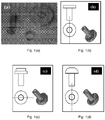
- Figure 1(a) is a photograph of the prior art approach to a pump out tube and solder glass preform, where the two components are used as individual components to be combined at the hole in the glass.
- Figures 1(b), (c) and (d) are illustrations of potential variations of the proposed invention where the component is a combined glass tube and solder glass preform;
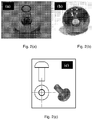
- Figures 2(a), (b) and (c) illustrate the formation of the pump out tube according to the invention, where the glass tube and solder glass preform were bonded by partially heating the preform to melt it and seal it to the glass tube;
- 2(b) shows the rear view of the combined tube and preform shown in figure 2(a);
- figure 2(c) is an illustration of the geometry of this form of the component as in figure 2(a) .
- a pump-out tube for evacuating a space between planar sheets, preferably glass panes comprising a tubular member and a seal formed around the tubular member, the seal comprising a heat treated preform heat sealed, or dry pressed, or cured from paste, to the tubular member.
- the preform may be one of a number of geometric shapes but in the preferred embodiment is annular shaped with the inner diameter of the preform conforming to the outer diameter of the tubular member.
- the planar sheets are preferably paired glass panes having a hole with a diameter at least the same size as the thickness of the glass pane formed therein. The hole and annular seal is sized to receive the annular seal at least partially within the hole.
- the diameter of the tubular member is less than the thickness of the sheets or panes of glass and less than the diameter of the hole.
- the preform may be provided with a stepped region where the diameter of the stepped region corresponds to the diameter of the hole. To make the preform more universally usable, multiple stepped regions may be provided see figure 1 (c) . Alternatively the preform may be conical shaped, see figure 1(d) .
- Solder glass or glass solder is a low melting point glass in which usually silica glass powder is mixed with materials such as organic binders, inorganic fillers and solvents are added to alter the thermal properties of the silica for binding, coating and sealing applications.
- solder glass materials There a number of commercially available solder glass materials.
- the solder glass may be vitreous or non-vitreous depending on whether the mixture forms a crystalline or non-crystalline structure when sintered to form a seal.
- the solder glass may be of a composition that is sintered with oxides, the dominant categories of which are the lead, bismuth, vanadium, tin, silver, and gold oxides. These oxides are sintered with various other oxides such as aluminium, zinc, calcium, potassium, iron, sodium, tellurium, titanium, oxides that allow for changes in thermal and mechanical properties to suit the glass onto which it is applied.
- the preform is separately fitted to the glass tubular member and the glass tubular member and solder glass preform are held together at one end of the tube.
- the solder glass is then heated until melting occurs. Once the solder glass wets to the tubular member surface and seals, the heating is removed or the combined tubular member and preform cooled.
- Figure 2 shows a 2 mm glass pump-out tube fused at one end to a larger diameter (5mm) preform of solder glass.
- the solder glass preform can be produced at different thicknesses and diameters or formed in-situ around the tubular member. Upon heating, the solder glass partially melts to secure the preform to the tubular member and the natural flow of the solder glass produces a cone shape at the end of the tube. This simplifies locating the preform on the hole on the glass pane.
- the invention utilises the existing components to effectively and simply solve the problem of sealing large diameter holes with a small diameter tube. There is no need for special geometries or new components. It is also possible that this product could be used in other technologies, such as flat panel displays.
- the heating of the solder glass must be controlled within limits depending on the thermal properties of the solder glass.
- the preferred solder glass used in embodiments of the invention melts between 320-480oC. If the heating is too quick then undesirable bubbles may form in the structure leading to premature cracking of the preform and/or the solder glass will deform significantly; once the optimum temperature and time of exposure has been determined the preform can be produced with great accuracy and reproducibility. Considering other industrial technologies, this pump out tube according to the invention could be produced with great speed and at low cost.
- the production process used in further embodiments of the invention may incorporate a process of dry pressing solder glass powder with a tubular member in a mould; or alternatively a wet paste of the solder glass with the tubular member could be cured in a mould, to produce a preform of solder glass attached to a glass tubular member.
- the solder glass geometry could be of any shape, such as annulus disk, annulus disk with an edge step, conical, square, etc.
- a glass tube of diameter 2 mm is placed in a mould that has a predefined geometry.
- the solder paste is prepared by mixing solder glass with a binder material, e.g. ethyl cellulose, which was first dissolved in an appropriate solvent. This mixture is formed at a viscosity less than 200 Pa sec, and then injected into the mould to fill the volume surrounding the glass tube.
- the combined preform and tube are then cured, at room temperature or in an oven for a specific time. Once cured the glass tube will adhere to the solder glass paste and both are removed as a single complete component. Production of vacuum induced glass panel.
- a 4mm hole is formed in the corner of a first glass substrate and the first and second glass substrate are positioned so that the planes of the glass are substantially parallel.
- An array of spacers/pillars are positioned between the substrates for spacing the substrates from one another and supporting them.
- Edge sealing material which is generally a solder glass is positioned around the peripheral edge of the substrates.
- the edge seal may be made of or include any of the following materials: solder glass (i.e. glass frit; an oxide inclusive mixture having a melting point lower than that of normal glass), ceramic, Indalloy No. 53 available from Indium Corp. in paste or wire form having a composition of 67% Bi and 33% In (% by weight), Indalloy No. 1 from Indium Corp. in paste or wire form having a composition of 50% In and 50% Sn, Indalloy No. 290 available from Indium Corp. in paste or wire form having a composition of 97% In and 3% Ag, Indalloy No. 9 from Indium Corp. in paste or wire form having a composition of 70% Sn, 18% Pb and 12% In, Indalloy No.
- solder glass i.e. glass frit; an oxide inclusive mixture having a melting point lower than that of normal glass
- ceramic i.e. glass frit; an oxide inclusive mixture having a melting point lower than that of normal glass
- Indalloy No. 53 available
- Indalloy No. 206 available from Indium Corp. in paste or wire form having a composition of 60% Pb and 40% In
- Indalloy No. 227 available from Indium Corp. in paste or wire form having a composition of 77.2% Sn, 20% In and 2.8% Ag
- Indalloy No. 2 available from Indium Corp. in paste or wire form having a composition of 80% In, 15% Pb and 5% Ag
- Indalloy No. 3 available from Indium Corp. in paste or wire form having a composition of 90% In and 10% Ag, or any other suitable hermetically sealing material.
- the substrates are then heated to a temperature to soften and form a hermetic seal around the periphery of the space between the substrates.
- the pump-out tube according to the invention is fitted into the 4 mm diameter hole formed in a glass substrate.
- the glass substrate is heated to a temperature of 380oC ⁇ 420oC for 15 to 30 minutes to enable the solder glass to soften and wet the interior of the hole in the glass and seal the pump-out tube into the glass pane. It is important not to heat the substrates for too long so as not to break down the structural integrity of the solder glass. If the pump out tube and glass panes are heated for too long or the temperature too high, the viscosity of the solder glass will deteriorate and the shape of the preform will soften to a level where it will not retain the tubular member in the hole. After placement on a flat sheet and upon heating, the solder glass would melt and seal to the tubular member and also seal to the flat sheet, which would be glass in most cases.
- the tube of the component should not have moved from its original position, with respect to its height and vertical alignment, by an amount greater than 0.2 mm. Changes in the original position, with respect to height and vertical alignment, which are greater than 0.2 mm, will render the tube of-no-use in the desired application.
- the pump out tube In order to evacuate the space between the glass substrates, the pump out tube is connected to a vacuum source and the gas in the space between the substrates reduced to a pressure equal to or below 0.01 hPa. The pump out tube is then sealed and the excess material above the glass substrate removed. The edge structure together with the pump-out tube eliminates the egress or outgress of gas to/from the space between the glass substrates.
Landscapes
- Engineering & Computer Science (AREA)
- Chemical & Material Sciences (AREA)
- Civil Engineering (AREA)
- Structural Engineering (AREA)
- Ceramic Engineering (AREA)
- Materials Engineering (AREA)
- Organic Chemistry (AREA)
- Life Sciences & Earth Sciences (AREA)
- Chemical Kinetics & Catalysis (AREA)
- General Chemical & Material Sciences (AREA)
- Geochemistry & Mineralogy (AREA)
- Joining Of Glass To Other Materials (AREA)
Claims (15)
- Tube de mise sous vide destiné à faire le vide dans un espace entre deux feuilles de verre séparées par un espace d'un panneau de verre, les deux feuilles de verre séparées par un espace entourant un espace et un trou formé dans au moins l'une des feuilles de verre, dans lequel le tube de mise sous vide peut être inséré dans le trou formé dans ladite au moins une des feuilles de verre afin de faire le vide dans l'espace entre lesdites deux feuilles de verre, caractérisé en ce que le tube de mise sous vide est formé en tant qu'un élément séparé avant l'adaptation du tube de mise sous vide au trou, et comprend un élément tubulaire et un joint d'étanchéité formé autour de l'élément tubulaire, et en ce que le joint d'étanchéité est dimensionné de manière à s'étendre au-delà des bords du trou afin de permettre au joint d'étanchéité de soutenir le membre tubulaire dans le trou, ledit joint d'étanchéité étant au moins en partie inséré dans le trou.
- Tube de mise sous vide selon la revendication 1, dans lequel le joint d'étanchéité est formé autour de l'élément tubulaire par une étape choisie dans le groupe constitué par i) thermoscellage d'une préforme traitée par la chaleur au membre tubulaire, ii) pressage à sec de matériau de préforme dans un moule sur le membre tubulaire et iii) mise sous forme d'une pâte de matériau de préforme et d'un liant, pressage du mélange dans un moule et durcissement du mélange de préforme sur le membre tubulaire.
- Tube de mise sous vide selon la revendication 1 ou 2, dans lequel un diamètre du membre tubulaire est inférieur à une épaisseur des feuilles de verre.
- Tube de mise sous vide selon la revendication 3, dans lequel le membre tubulaire est un tube en verre et la préforme est constituée de verre de scellement.
- Tube de mise sous vide selon l'une quelconque des revendications 2 à 4, dans lequel la préforme est mise en forme avec une zone en gradin qui peut être utilisée pour placer le tube de mise sous vide dans le trou formé dans ladite au moins une des feuilles de verre.
- Tube de mise sous vide selon la revendication 5, dans lequel la zone en gradin a un diamètre qui est le même que le diamètre du trou.
- Tube de mise sous vide selon l'une quelconque des revendications 2 à 4, dans lequel la préforme a une forme conique divergeant vers le trou formé dans au moins l'une des feuilles de verre, dans laquelle elle est destinée à être adaptée.
- Tube de mise sous vide selon l'une quelconque des revendications 2 à 7, dans lequel la préforme a une forme annulaire, le diamètre interne de la préforme correspondant au diamètre externe du membre tubulaire.
- Procédé de production d'un tube de mise sous vide approprié à être utilisé avec un panneau de verre comprenant deux feuilles de verre séparées par un espace, entourant un espace et un trou formé dans au moins l'une des feuilles de verre, dans lequel le procédé comprend les étapes consistant à appliquer, par formage ou adaptation, une préforme sur une extrémité d'un membre tubulaire, chauffer la préforme jusqu'à une température pour fondre au moins en partie la préforme afin de fixer la préforme au membre tubulaire pour former ledit tube de mise sous vide, caractérisé en ce que le tube de mise sous vide est produit en tant qu'un élément séparé avant l'adaptation du tube de mise sous vide au trou formé dans ladite au moins une des feuilles de verre, et en ce que la préforme est dimensionnée de manière à s'étendre au-delà des bords du trou afin de permettre à la préforme de soutenir le membre tubulaire dans le trou, ladite préforme étant au moins en partie insérée dans le trou.
- Procédé selon la revendication 9, dans lequel le membre tubulaire a un diamètre inférieur à une épaisseur des feuilles de verre et le membre tubulaire est un tube en verre.
- Procédé selon la revendication 9 ou 10, dans lequel la préforme est une préforme en verre de scellement.
- Procédé selon l'une quelconque des revendications 9 à 11, dans lequel la préforme a une forme annulaire, un diamètre interne de la préforme correspondant à un diamètre externe du membre tubulaire, la préforme chauffée mouille la surface de l'élément tubulaire pour sceller la préforme à l'élément tubulaire lorsque le chauffage est retiré et/ou la préforme et l'élément tubulaire sont refroidis.
- Procédé selon l'une quelconque des revendications 9 à 12, dans lequel la préforme a une forme choisie dans le groupe constitué par un carré, un cercle ou toute autre forme géométrique comportant un retrait formé dans celle-ci, correspondant au diamètre externe de l'élément tubulaire.
- Procédé selon l'une quelconque des revendications 9 à 12, dans lequel la préforme a une forme annulaire, le diamètre d'un retrait dans la préforme correspondant au diamètre externe du membre tubulaire.
- Procédé selon l'une quelconque des revendications 9 à 14, dans lequel la préforme chauffée mouille la surface de l'élément tubulaire pour sceller la préforme à l'élément tubulaire lorsque le chauffage est retiré et/ou la préforme et l'élément tubulaire sont refroidis.
Priority Applications (1)
| Application Number | Priority Date | Filing Date | Title |
|---|---|---|---|
| PL16806442T PL3307977T3 (pl) | 2015-06-11 | 2016-06-10 | Preforma rurki wypompowującej |
Applications Claiming Priority (2)
| Application Number | Priority Date | Filing Date | Title |
|---|---|---|---|
| AU2015902353A AU2015902353A0 (en) | 2015-06-11 | Pump out tube preform | |
| PCT/AU2016/050471 WO2016197199A1 (fr) | 2015-06-11 | 2016-06-10 | Préforme de tube de mise sous vide |
Publications (3)
| Publication Number | Publication Date |
|---|---|
| EP3307977A1 EP3307977A1 (fr) | 2018-04-18 |
| EP3307977A4 EP3307977A4 (fr) | 2018-12-05 |
| EP3307977B1 true EP3307977B1 (fr) | 2021-12-08 |
Family
ID=57502867
Family Applications (1)
| Application Number | Title | Priority Date | Filing Date |
|---|---|---|---|
| EP16806442.6A Not-in-force EP3307977B1 (fr) | 2015-06-11 | 2016-06-10 | Préforme de tube de mise sous vide |
Country Status (5)
| Country | Link |
|---|---|
| US (2) | US20180163457A1 (fr) |
| EP (1) | EP3307977B1 (fr) |
| AU (1) | AU2016275569B2 (fr) |
| PL (1) | PL3307977T3 (fr) |
| WO (1) | WO2016197199A1 (fr) |
Families Citing this family (1)
| Publication number | Priority date | Publication date | Assignee | Title |
|---|---|---|---|---|
| EP3363982B1 (fr) | 2017-02-17 | 2019-07-31 | VKR Holding A/S | Unité de vitrage isolé sous vide |
Family Cites Families (9)
| Publication number | Priority date | Publication date | Assignee | Title |
|---|---|---|---|---|
| CN1078659C (zh) * | 1993-06-30 | 2002-01-30 | 悉尼大学 | 制造真空玻璃窗的方法 |
| JP3859771B2 (ja) * | 1996-06-17 | 2006-12-20 | 日本板硝子株式会社 | 真空複層ガラス及びその製造方法 |
| JP2000203892A (ja) * | 1999-01-18 | 2000-07-25 | Nippon Sheet Glass Co Ltd | ガラスパネル |
| US6383580B1 (en) * | 1999-11-12 | 2002-05-07 | Guardian Industries Corp. | Vacuum IG window unit with edge mounted pump-out tube |
| US6692600B2 (en) * | 2001-09-14 | 2004-02-17 | Guardian Industries Corp. | VIG evacuation with plasma excitation |
| US7476426B2 (en) * | 2002-09-05 | 2009-01-13 | Boe Technology Group Co., Ltd. | Evacuated glass panel having degassing device |
| JP5476850B2 (ja) * | 2009-08-14 | 2014-04-23 | 日本電気硝子株式会社 | タブレットおよびタブレット一体型排気管 |
| US8833105B2 (en) * | 2012-05-18 | 2014-09-16 | Guardian Industries Corp. | Method and apparatus for making vacuum insulated glass (VIG) window unit including pump-out tube sealing technique |
| US9593527B2 (en) * | 2014-02-04 | 2017-03-14 | Guardian Industries Corp. | Vacuum insulating glass (VIG) unit with lead-free dual-frit edge seals and/or methods of making the same |
-
2016
- 2016-06-10 EP EP16806442.6A patent/EP3307977B1/fr not_active Not-in-force
- 2016-06-10 US US15/580,926 patent/US20180163457A1/en not_active Abandoned
- 2016-06-10 WO PCT/AU2016/050471 patent/WO2016197199A1/fr not_active Ceased
- 2016-06-10 AU AU2016275569A patent/AU2016275569B2/en not_active Ceased
- 2016-06-10 PL PL16806442T patent/PL3307977T3/pl unknown
-
2021
- 2021-07-21 US US17/381,596 patent/US20210348439A1/en not_active Abandoned
Non-Patent Citations (1)
| Title |
|---|
| None * |
Also Published As
| Publication number | Publication date |
|---|---|
| US20210348439A1 (en) | 2021-11-11 |
| EP3307977A4 (fr) | 2018-12-05 |
| EP3307977A1 (fr) | 2018-04-18 |
| WO2016197199A1 (fr) | 2016-12-15 |
| US20180163457A1 (en) | 2018-06-14 |
| AU2016275569A8 (en) | 2018-01-18 |
| PL3307977T3 (pl) | 2022-05-02 |
| AU2016275569B2 (en) | 2020-02-27 |
| AU2016275569A1 (en) | 2018-01-04 |
Similar Documents
| Publication | Publication Date | Title |
|---|---|---|
| EP0953718B1 (fr) | Procédé de construction d'un vitrage sous vide | |
| JP6471917B2 (ja) | 複層ガラスの製造方法 | |
| US6701749B2 (en) | Vacuum IG window unit with edge seal at least partially diffused at temper and completed via microwave curing, and corresponding method of making the same | |
| US6558494B1 (en) | Vacuum IG window unit with edge seal at least partially diffused at temper and completed via microwave curing, and corresponding method of making the same | |
| EP2855816B1 (fr) | Procédé de réalisation d'une unité de fenêtre en verre à isolation sous vide (vig) affichant une variation réduite de la hauteur du joint | |
| JP4223556B2 (ja) | 2枚のガラスの間に真空を形成し窓ガラスを絶縁する方法 | |
| JP3082046B2 (ja) | 断熱ガラスパネル及びその構築方法 | |
| JP6495928B2 (ja) | 真空断熱ガラス(vig)ユニットに使用されるフリット、及び/又は関連方法 | |
| US20020197423A1 (en) | Vacuum IG window unit with edge seal formed via microwave curing, and corresponding method of making the same | |
| CN103588386B (zh) | 钢化真空玻璃的生产方法 | |
| US20100330309A1 (en) | Frit or solder glass compound including beads, and assemblies incorporating the same | |
| JPWO2016017709A1 (ja) | 真空複層ガラスの製造方法、および真空複層ガラス | |
| JP2017509573A (ja) | 無鉛二重フリット端部シールを有する真空断熱ガラス(vig)ユニット及び/又はその製造方法 | |
| EP3583080B1 (fr) | Traitement thermique de fritte supérieure | |
| JP6507461B2 (ja) | ガラスパネルユニットの製造方法およびガラス窓の製造方法 | |
| US20210348439A1 (en) | Pump out tube preform | |
| US20080063839A1 (en) | Architectural glass block with a formed slot and method of making same | |
| WO2026063457A1 (fr) | Matériau d'étanchéité et panneau de double vitrage | |
| GB2580172A (en) | Vacuum insulated glazing unit | |
| JP2000220357A (ja) | 低圧複層ガラスおよびその製造方法 |
Legal Events
| Date | Code | Title | Description |
|---|---|---|---|
| STAA | Information on the status of an ep patent application or granted ep patent |
Free format text: STATUS: THE INTERNATIONAL PUBLICATION HAS BEEN MADE |
|
| PUAI | Public reference made under article 153(3) epc to a published international application that has entered the european phase |
Free format text: ORIGINAL CODE: 0009012 |
|
| STAA | Information on the status of an ep patent application or granted ep patent |
Free format text: STATUS: REQUEST FOR EXAMINATION WAS MADE |
|
| 17P | Request for examination filed |
Effective date: 20180102 |
|
| AK | Designated contracting states |
Kind code of ref document: A1 Designated state(s): AL AT BE BG CH CY CZ DE DK EE ES FI FR GB GR HR HU IE IS IT LI LT LU LV MC MK MT NL NO PL PT RO RS SE SI SK SM TR |
|
| AX | Request for extension of the european patent |
Extension state: BA ME |
|
| DAV | Request for validation of the european patent (deleted) | ||
| DAX | Request for extension of the european patent (deleted) | ||
| A4 | Supplementary search report drawn up and despatched |
Effective date: 20181025 |
|
| RIC1 | Information provided on ipc code assigned before grant |
Ipc: C03C 27/00 20060101ALI20181020BHEP Ipc: C03C 27/04 20060101ALI20181020BHEP Ipc: C03B 23/20 20060101ALI20181020BHEP Ipc: C03C 27/06 20060101ALI20181020BHEP Ipc: E06B 3/66 20060101ALI20181020BHEP Ipc: E06B 3/677 20060101AFI20181020BHEP |
|
| STAA | Information on the status of an ep patent application or granted ep patent |
Free format text: STATUS: EXAMINATION IS IN PROGRESS |
|
| 17Q | First examination report despatched |
Effective date: 20200107 |
|
| GRAP | Despatch of communication of intention to grant a patent |
Free format text: ORIGINAL CODE: EPIDOSNIGR1 |
|
| STAA | Information on the status of an ep patent application or granted ep patent |
Free format text: STATUS: GRANT OF PATENT IS INTENDED |
|
| INTG | Intention to grant announced |
Effective date: 20210630 |
|
| GRAS | Grant fee paid |
Free format text: ORIGINAL CODE: EPIDOSNIGR3 |
|
| GRAA | (expected) grant |
Free format text: ORIGINAL CODE: 0009210 |
|
| STAA | Information on the status of an ep patent application or granted ep patent |
Free format text: STATUS: THE PATENT HAS BEEN GRANTED |
|
| AK | Designated contracting states |
Kind code of ref document: B1 Designated state(s): AL AT BE BG CH CY CZ DE DK EE ES FI FR GB GR HR HU IE IS IT LI LT LU LV MC MK MT NL NO PL PT RO RS SE SI SK SM TR |
|
| REG | Reference to a national code |
Ref country code: GB Ref legal event code: FG4D |
|
| REG | Reference to a national code |
Ref country code: AT Ref legal event code: REF Ref document number: 1453911 Country of ref document: AT Kind code of ref document: T Effective date: 20211215 Ref country code: CH Ref legal event code: EP |
|
| REG | Reference to a national code |
Ref country code: DE Ref legal event code: R096 Ref document number: 602016067188 Country of ref document: DE |
|
| REG | Reference to a national code |
Ref country code: IE Ref legal event code: FG4D |
|
| REG | Reference to a national code |
Ref country code: LT Ref legal event code: MG9D |
|
| REG | Reference to a national code |
Ref country code: NL Ref legal event code: MP Effective date: 20211208 |
|
| PG25 | Lapsed in a contracting state [announced via postgrant information from national office to epo] |
Ref country code: RS Free format text: LAPSE BECAUSE OF FAILURE TO SUBMIT A TRANSLATION OF THE DESCRIPTION OR TO PAY THE FEE WITHIN THE PRESCRIBED TIME-LIMIT Effective date: 20211208 Ref country code: LT Free format text: LAPSE BECAUSE OF FAILURE TO SUBMIT A TRANSLATION OF THE DESCRIPTION OR TO PAY THE FEE WITHIN THE PRESCRIBED TIME-LIMIT Effective date: 20211208 Ref country code: FI Free format text: LAPSE BECAUSE OF FAILURE TO SUBMIT A TRANSLATION OF THE DESCRIPTION OR TO PAY THE FEE WITHIN THE PRESCRIBED TIME-LIMIT Effective date: 20211208 Ref country code: BG Free format text: LAPSE BECAUSE OF FAILURE TO SUBMIT A TRANSLATION OF THE DESCRIPTION OR TO PAY THE FEE WITHIN THE PRESCRIBED TIME-LIMIT Effective date: 20220308 |
|
| REG | Reference to a national code |
Ref country code: AT Ref legal event code: MK05 Ref document number: 1453911 Country of ref document: AT Kind code of ref document: T Effective date: 20211208 |
|
| PG25 | Lapsed in a contracting state [announced via postgrant information from national office to epo] |
Ref country code: SE Free format text: LAPSE BECAUSE OF FAILURE TO SUBMIT A TRANSLATION OF THE DESCRIPTION OR TO PAY THE FEE WITHIN THE PRESCRIBED TIME-LIMIT Effective date: 20211208 Ref country code: NO Free format text: LAPSE BECAUSE OF FAILURE TO SUBMIT A TRANSLATION OF THE DESCRIPTION OR TO PAY THE FEE WITHIN THE PRESCRIBED TIME-LIMIT Effective date: 20220308 Ref country code: LV Free format text: LAPSE BECAUSE OF FAILURE TO SUBMIT A TRANSLATION OF THE DESCRIPTION OR TO PAY THE FEE WITHIN THE PRESCRIBED TIME-LIMIT Effective date: 20211208 Ref country code: HR Free format text: LAPSE BECAUSE OF FAILURE TO SUBMIT A TRANSLATION OF THE DESCRIPTION OR TO PAY THE FEE WITHIN THE PRESCRIBED TIME-LIMIT Effective date: 20211208 Ref country code: GR Free format text: LAPSE BECAUSE OF FAILURE TO SUBMIT A TRANSLATION OF THE DESCRIPTION OR TO PAY THE FEE WITHIN THE PRESCRIBED TIME-LIMIT Effective date: 20220309 Ref country code: ES Free format text: LAPSE BECAUSE OF FAILURE TO SUBMIT A TRANSLATION OF THE DESCRIPTION OR TO PAY THE FEE WITHIN THE PRESCRIBED TIME-LIMIT Effective date: 20211208 |
|
| PG25 | Lapsed in a contracting state [announced via postgrant information from national office to epo] |
Ref country code: NL Free format text: LAPSE BECAUSE OF FAILURE TO SUBMIT A TRANSLATION OF THE DESCRIPTION OR TO PAY THE FEE WITHIN THE PRESCRIBED TIME-LIMIT Effective date: 20211208 |
|
| PG25 | Lapsed in a contracting state [announced via postgrant information from national office to epo] |
Ref country code: SM Free format text: LAPSE BECAUSE OF FAILURE TO SUBMIT A TRANSLATION OF THE DESCRIPTION OR TO PAY THE FEE WITHIN THE PRESCRIBED TIME-LIMIT Effective date: 20211208 Ref country code: SK Free format text: LAPSE BECAUSE OF FAILURE TO SUBMIT A TRANSLATION OF THE DESCRIPTION OR TO PAY THE FEE WITHIN THE PRESCRIBED TIME-LIMIT Effective date: 20211208 Ref country code: RO Free format text: LAPSE BECAUSE OF FAILURE TO SUBMIT A TRANSLATION OF THE DESCRIPTION OR TO PAY THE FEE WITHIN THE PRESCRIBED TIME-LIMIT Effective date: 20211208 Ref country code: PT Free format text: LAPSE BECAUSE OF FAILURE TO SUBMIT A TRANSLATION OF THE DESCRIPTION OR TO PAY THE FEE WITHIN THE PRESCRIBED TIME-LIMIT Effective date: 20220408 Ref country code: EE Free format text: LAPSE BECAUSE OF FAILURE TO SUBMIT A TRANSLATION OF THE DESCRIPTION OR TO PAY THE FEE WITHIN THE PRESCRIBED TIME-LIMIT Effective date: 20211208 Ref country code: CZ Free format text: LAPSE BECAUSE OF FAILURE TO SUBMIT A TRANSLATION OF THE DESCRIPTION OR TO PAY THE FEE WITHIN THE PRESCRIBED TIME-LIMIT Effective date: 20211208 |
|
| PG25 | Lapsed in a contracting state [announced via postgrant information from national office to epo] |
Ref country code: AT Free format text: LAPSE BECAUSE OF FAILURE TO SUBMIT A TRANSLATION OF THE DESCRIPTION OR TO PAY THE FEE WITHIN THE PRESCRIBED TIME-LIMIT Effective date: 20211208 |
|
| REG | Reference to a national code |
Ref country code: DE Ref legal event code: R097 Ref document number: 602016067188 Country of ref document: DE |
|
| PG25 | Lapsed in a contracting state [announced via postgrant information from national office to epo] |
Ref country code: IS Free format text: LAPSE BECAUSE OF FAILURE TO SUBMIT A TRANSLATION OF THE DESCRIPTION OR TO PAY THE FEE WITHIN THE PRESCRIBED TIME-LIMIT Effective date: 20220408 |
|
| PLBE | No opposition filed within time limit |
Free format text: ORIGINAL CODE: 0009261 |
|
| STAA | Information on the status of an ep patent application or granted ep patent |
Free format text: STATUS: NO OPPOSITION FILED WITHIN TIME LIMIT |
|
| PG25 | Lapsed in a contracting state [announced via postgrant information from national office to epo] |
Ref country code: DK Free format text: LAPSE BECAUSE OF FAILURE TO SUBMIT A TRANSLATION OF THE DESCRIPTION OR TO PAY THE FEE WITHIN THE PRESCRIBED TIME-LIMIT Effective date: 20211208 Ref country code: AL Free format text: LAPSE BECAUSE OF FAILURE TO SUBMIT A TRANSLATION OF THE DESCRIPTION OR TO PAY THE FEE WITHIN THE PRESCRIBED TIME-LIMIT Effective date: 20211208 |
|
| 26N | No opposition filed |
Effective date: 20220909 |
|
| PG25 | Lapsed in a contracting state [announced via postgrant information from national office to epo] |
Ref country code: SI Free format text: LAPSE BECAUSE OF FAILURE TO SUBMIT A TRANSLATION OF THE DESCRIPTION OR TO PAY THE FEE WITHIN THE PRESCRIBED TIME-LIMIT Effective date: 20211208 |
|
| PG25 | Lapsed in a contracting state [announced via postgrant information from national office to epo] |
Ref country code: MC Free format text: LAPSE BECAUSE OF FAILURE TO SUBMIT A TRANSLATION OF THE DESCRIPTION OR TO PAY THE FEE WITHIN THE PRESCRIBED TIME-LIMIT Effective date: 20211208 |
|
| REG | Reference to a national code |
Ref country code: CH Ref legal event code: PL |
|
| REG | Reference to a national code |
Ref country code: BE Ref legal event code: MM Effective date: 20220630 |
|
| PG25 | Lapsed in a contracting state [announced via postgrant information from national office to epo] |
Ref country code: LU Free format text: LAPSE BECAUSE OF NON-PAYMENT OF DUE FEES Effective date: 20220610 Ref country code: LI Free format text: LAPSE BECAUSE OF NON-PAYMENT OF DUE FEES Effective date: 20220630 Ref country code: IE Free format text: LAPSE BECAUSE OF NON-PAYMENT OF DUE FEES Effective date: 20220610 Ref country code: CH Free format text: LAPSE BECAUSE OF NON-PAYMENT OF DUE FEES Effective date: 20220630 |
|
| PG25 | Lapsed in a contracting state [announced via postgrant information from national office to epo] |
Ref country code: IT Free format text: LAPSE BECAUSE OF FAILURE TO SUBMIT A TRANSLATION OF THE DESCRIPTION OR TO PAY THE FEE WITHIN THE PRESCRIBED TIME-LIMIT Effective date: 20211208 Ref country code: BE Free format text: LAPSE BECAUSE OF NON-PAYMENT OF DUE FEES Effective date: 20220630 |
|
| P01 | Opt-out of the competence of the unified patent court (upc) registered |
Effective date: 20230606 |
|
| PGFP | Annual fee paid to national office [announced via postgrant information from national office to epo] |
Ref country code: FR Payment date: 20230628 Year of fee payment: 8 Ref country code: DE Payment date: 20230620 Year of fee payment: 8 |
|
| PGFP | Annual fee paid to national office [announced via postgrant information from national office to epo] |
Ref country code: PL Payment date: 20230602 Year of fee payment: 8 |
|
| PGFP | Annual fee paid to national office [announced via postgrant information from national office to epo] |
Ref country code: GB Payment date: 20230622 Year of fee payment: 8 |
|
| PG25 | Lapsed in a contracting state [announced via postgrant information from national office to epo] |
Ref country code: HU Free format text: LAPSE BECAUSE OF FAILURE TO SUBMIT A TRANSLATION OF THE DESCRIPTION OR TO PAY THE FEE WITHIN THE PRESCRIBED TIME-LIMIT; INVALID AB INITIO Effective date: 20160610 |
|
| PG25 | Lapsed in a contracting state [announced via postgrant information from national office to epo] |
Ref country code: MK Free format text: LAPSE BECAUSE OF FAILURE TO SUBMIT A TRANSLATION OF THE DESCRIPTION OR TO PAY THE FEE WITHIN THE PRESCRIBED TIME-LIMIT Effective date: 20211208 Ref country code: CY Free format text: LAPSE BECAUSE OF FAILURE TO SUBMIT A TRANSLATION OF THE DESCRIPTION OR TO PAY THE FEE WITHIN THE PRESCRIBED TIME-LIMIT Effective date: 20211208 |
|
| PG25 | Lapsed in a contracting state [announced via postgrant information from national office to epo] |
Ref country code: MT Free format text: LAPSE BECAUSE OF FAILURE TO SUBMIT A TRANSLATION OF THE DESCRIPTION OR TO PAY THE FEE WITHIN THE PRESCRIBED TIME-LIMIT Effective date: 20211208 |
|
| REG | Reference to a national code |
Ref country code: DE Ref legal event code: R119 Ref document number: 602016067188 Country of ref document: DE |
|
| GBPC | Gb: european patent ceased through non-payment of renewal fee |
Effective date: 20240610 |
|
| PG25 | Lapsed in a contracting state [announced via postgrant information from national office to epo] |
Ref country code: DE Free format text: LAPSE BECAUSE OF NON-PAYMENT OF DUE FEES Effective date: 20250101 |
|
| PG25 | Lapsed in a contracting state [announced via postgrant information from national office to epo] |
Ref country code: FR Free format text: LAPSE BECAUSE OF NON-PAYMENT OF DUE FEES Effective date: 20240630 |
|
| PG25 | Lapsed in a contracting state [announced via postgrant information from national office to epo] |
Ref country code: GB Free format text: LAPSE BECAUSE OF NON-PAYMENT OF DUE FEES Effective date: 20240610 |
|
| PG25 | Lapsed in a contracting state [announced via postgrant information from national office to epo] |
Ref country code: PL Free format text: LAPSE BECAUSE OF NON-PAYMENT OF DUE FEES Effective date: 20240610 |
|
| PG25 | Lapsed in a contracting state [announced via postgrant information from national office to epo] |
Ref country code: TR Free format text: LAPSE BECAUSE OF FAILURE TO SUBMIT A TRANSLATION OF THE DESCRIPTION OR TO PAY THE FEE WITHIN THE PRESCRIBED TIME-LIMIT Effective date: 20211208 |