EP3307982B1 - Ankermodul, gehäusestopfenanordnung und verfahren zum betrieb einer gehäusestopfenanordnung in einem brunnenrohr - Google Patents
Ankermodul, gehäusestopfenanordnung und verfahren zum betrieb einer gehäusestopfenanordnung in einem brunnenrohr Download PDFInfo
- Publication number
- EP3307982B1 EP3307982B1 EP16725150.3A EP16725150A EP3307982B1 EP 3307982 B1 EP3307982 B1 EP 3307982B1 EP 16725150 A EP16725150 A EP 16725150A EP 3307982 B1 EP3307982 B1 EP 3307982B1
- Authority
- EP
- European Patent Office
- Prior art keywords
- module
- plug assembly
- slips
- fluid
- casing plug
- Prior art date
- Legal status (The legal status is an assumption and is not a legal conclusion. Google has not performed a legal analysis and makes no representation as to the accuracy of the status listed.)
- Active
Links
Images




Classifications
-
- E—FIXED CONSTRUCTIONS
- E21—EARTH OR ROCK DRILLING; MINING
- E21B—EARTH OR ROCK DRILLING; OBTAINING OIL, GAS, WATER, SOLUBLE OR MELTABLE MATERIALS OR A SLURRY OF MINERALS FROM WELLS
- E21B33/00—Sealing or packing boreholes or wells
- E21B33/10—Sealing or packing boreholes or wells in the borehole
- E21B33/12—Packers; Plugs
- E21B33/129—Packers; Plugs with mechanical slips for hooking into the casing
- E21B33/1295—Packers; Plugs with mechanical slips for hooking into the casing actuated by fluid pressure
- E21B33/12955—Packers; Plugs with mechanical slips for hooking into the casing actuated by fluid pressure using drag blocks frictionally engaging the inner wall of the well
-
- E—FIXED CONSTRUCTIONS
- E21—EARTH OR ROCK DRILLING; MINING
- E21B—EARTH OR ROCK DRILLING; OBTAINING OIL, GAS, WATER, SOLUBLE OR MELTABLE MATERIALS OR A SLURRY OF MINERALS FROM WELLS
- E21B23/00—Apparatus for displacing, setting, locking, releasing or removing tools, packers or the like in boreholes or wells
- E21B23/01—Apparatus for displacing, setting, locking, releasing or removing tools, packers or the like in boreholes or wells for anchoring the tools or the like
-
- E—FIXED CONSTRUCTIONS
- E21—EARTH OR ROCK DRILLING; MINING
- E21B—EARTH OR ROCK DRILLING; OBTAINING OIL, GAS, WATER, SOLUBLE OR MELTABLE MATERIALS OR A SLURRY OF MINERALS FROM WELLS
- E21B33/00—Sealing or packing boreholes or wells
- E21B33/10—Sealing or packing boreholes or wells in the borehole
- E21B33/12—Packers; Plugs
- E21B33/128—Packers; Plugs with a member expanded radially by axial pressure
-
- E—FIXED CONSTRUCTIONS
- E21—EARTH OR ROCK DRILLING; MINING
- E21B—EARTH OR ROCK DRILLING; OBTAINING OIL, GAS, WATER, SOLUBLE OR MELTABLE MATERIALS OR A SLURRY OF MINERALS FROM WELLS
- E21B33/00—Sealing or packing boreholes or wells
- E21B33/10—Sealing or packing boreholes or wells in the borehole
- E21B33/12—Packers; Plugs
- E21B33/128—Packers; Plugs with a member expanded radially by axial pressure
- E21B33/1285—Packers; Plugs with a member expanded radially by axial pressure by fluid pressure
-
- E—FIXED CONSTRUCTIONS
- E21—EARTH OR ROCK DRILLING; MINING
- E21B—EARTH OR ROCK DRILLING; OBTAINING OIL, GAS, WATER, SOLUBLE OR MELTABLE MATERIALS OR A SLURRY OF MINERALS FROM WELLS
- E21B33/00—Sealing or packing boreholes or wells
- E21B33/10—Sealing or packing boreholes or wells in the borehole
- E21B33/12—Packers; Plugs
- E21B33/129—Packers; Plugs with mechanical slips for hooking into the casing
- E21B33/1291—Packers; Plugs with mechanical slips for hooking into the casing anchor set by wedge or cam in combination with frictional effect, using so-called drag-blocks
-
- E—FIXED CONSTRUCTIONS
- E21—EARTH OR ROCK DRILLING; MINING
- E21B—EARTH OR ROCK DRILLING; OBTAINING OIL, GAS, WATER, SOLUBLE OR MELTABLE MATERIALS OR A SLURRY OF MINERALS FROM WELLS
- E21B33/00—Sealing or packing boreholes or wells
- E21B33/10—Sealing or packing boreholes or wells in the borehole
- E21B33/12—Packers; Plugs
- E21B33/129—Packers; Plugs with mechanical slips for hooking into the casing
- E21B33/1291—Packers; Plugs with mechanical slips for hooking into the casing anchor set by wedge or cam in combination with frictional effect, using so-called drag-blocks
- E21B33/1292—Packers; Plugs with mechanical slips for hooking into the casing anchor set by wedge or cam in combination with frictional effect, using so-called drag-blocks with means for anchoring against downward and upward movement
-
- E—FIXED CONSTRUCTIONS
- E21—EARTH OR ROCK DRILLING; MINING
- E21B—EARTH OR ROCK DRILLING; OBTAINING OIL, GAS, WATER, SOLUBLE OR MELTABLE MATERIALS OR A SLURRY OF MINERALS FROM WELLS
- E21B33/00—Sealing or packing boreholes or wells
- E21B33/10—Sealing or packing boreholes or wells in the borehole
- E21B33/12—Packers; Plugs
- E21B33/129—Packers; Plugs with mechanical slips for hooking into the casing
- E21B33/1293—Packers; Plugs with mechanical slips for hooking into the casing with means for anchoring against downward and upward movement
-
- E—FIXED CONSTRUCTIONS
- E21—EARTH OR ROCK DRILLING; MINING
- E21B—EARTH OR ROCK DRILLING; OBTAINING OIL, GAS, WATER, SOLUBLE OR MELTABLE MATERIALS OR A SLURRY OF MINERALS FROM WELLS
- E21B33/00—Sealing or packing boreholes or wells
- E21B33/10—Sealing or packing boreholes or wells in the borehole
- E21B33/12—Packers; Plugs
- E21B33/129—Packers; Plugs with mechanical slips for hooking into the casing
- E21B33/1295—Packers; Plugs with mechanical slips for hooking into the casing actuated by fluid pressure
-
- E—FIXED CONSTRUCTIONS
- E21—EARTH OR ROCK DRILLING; MINING
- E21B—EARTH OR ROCK DRILLING; OBTAINING OIL, GAS, WATER, SOLUBLE OR MELTABLE MATERIALS OR A SLURRY OF MINERALS FROM WELLS
- E21B33/00—Sealing or packing boreholes or wells
- E21B33/10—Sealing or packing boreholes or wells in the borehole
- E21B33/13—Methods or devices for cementing, for plugging holes, crevices or the like
- E21B33/134—Bridging plugs
Definitions
- the present invention relates to a casing plug.
- the present invention also relates to a well anchor, which may be used together with the casing plug, but which may also be used with other well tools.
- plugs used in hydrocarbon producing wells.
- Such plugs may be retrievable plugs, i.e. they may be retrieved from the well after their use, or they may be permanent plugs, i.e. they are set permanently and must be milled/drilled into pieces in order to be removed.
- the well plug may comprise an anchor device, which in the set state (radially expanded state) is in contact with the inner surface of the well pipe. Its primary object is to prevent upwardly and/or downwardly directed movement of the plug in relation to the well pipe.
- the well plug may also comprise a sealing device, which in the set state (radially expanded state) also is in contact with the inner surface of the well pipe. Its primary object is to prevent fluid to pass the annular space between the outer surface of the plug and the inner surface of the well pipe.
- Plugs are set by means of a running tool lowered into the well.
- the running tool is connected to the plug, and at the desired depth, the running tool is actuated and the plug is brought from its run state (radially retracted state) to its set state (radially expanded state).
- One common connection interface between a plug and a running tool comprises an inner mandrel of the plug connected to an inner mandrel of the running tool and an outer housing of the plug connected to an outer housing of the running tool.
- Casing plugs are one type of well plug used during completion of a hydrocarbon well, during temporary plugging and abandonment (P&A) of the well etc.
- the casing plug is set in the casing pipe by using drill pipe to run the plug, to set the plug and also to retrieve the plug.
- the object of the present disclosure is to provide a casing plug with the following capabilities:
- Drag blocks are typically connected to the plug via coil springs, allowing the drag-blocks to move in relation to the plug due to irregularities of the inner surface of the casing etc.
- the friction is however sufficient to form an initial anchor which keeps some parts of the plug stationary while moving other parts by means of the pipe string.
- US 3714983 One example is shown in US 3714983 .
- US 3 426 846 considered the closest prior art, describes a retrievable well packer with two different slips for contacting the inner surface of the well pipe.
- One of the slips is fluid actuated, the other one is actuated by means of drag blocks.
- the invention relates to a method for operating a casing plug assembly in a well pipe, as defined in claim 1.
- the invention also relates to a casing plug assembly as defined in claim 5.
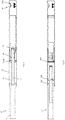
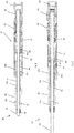
- a casing plug assembly 1 comprising a running tool 10, an equalizing module 20, a seal module 30 and an anchor module 50.
- the modules 20, 30 and 50 together form a casing plug.
- the upper side i.e. the side of the assembly being closest to the top of the well
- the lower side i.e. the side of the assembly being closest to the bottom of the well
- the axial direction is indicated by a dashed line I in fig. 1 .
- a continuous fluid channel 2 is formed through the casing plug assembly 1, as shown in fig. 1 and 2 .
- the upper part of the running tool 10 comprises a drill string connector section 3.
- the casing plug assembly 1 is run on drill string connector section 3 into the well.
- the lower part of the casing plug assembly 1 comprises a connection interface (not shown) for connection to a drill string connector section below the assembly 1.
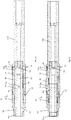
- the running tool 10 will now be described with reference to fig. 4 and 5 .
- the running tool 10 comprises an outer running tool housing 11 with an inner running tool sleeve 13.
- the upper part of the outer housing 11 and the upper part of the inner sleeve 13 are connected to the drill pipe connector section 3, which again can be connected to a section of drill pipe. Consequently, reference number 3 may also be considered to represent a section of a drill pipe.
- a through bore 12 forming a part of the fluid channel 2 is indicated in fig. 4 and 5 .
- the running tool 10 further comprises three lower connection interfaces in the form of a first connector 16 provided radially between the inner sleeve 13 and the outer housing 11, a second connector 17 provided in the lower part of the inner sleeve 13 and a third connector 19 provided in the lower part of the outer housing 11.
- the third connector 19 comprises inwardly protruding pins 19a.
- the inner sleeve 13 is axially displaceable in relation to the outer housing 11.
- the running tool 10 comprises a releasable connector indicated as 18a/b in fig 4 .
- the purpose of the releasable connector 18a/b is to open and close an equalizing sleeve, which will be described below.
- the connector has been released, as there is a distance between the connector element 18b following the inner sleeve 13 and the connector element 18a fixed to the outer housing 11.
- An upwardly directed force applied to the sleeve 13 is required to be above a certain threshold in order to release the connection elements 18a and b away from each other.
- a stop 18c will prevent further upwardly directed movement of the inner sleeve 13.
- the equalizing module 20 will now be described with reference to fig. 6 and 7 .
- the main purpose of the equalizing module 20 is to provide a valve function, which is open and allows fluid flow through the module 20 in the run and set state, and which is closed and prevents fluid flow through the module 20 in the abandoned state.
- the equalizing module 20 comprises an equalizing housing 21 with a through bore 22 forming a part of the fluid channel 2, and an equalizing sleeve 23 provided within the equalizing housing 21.
- the equalizing sleeve 23 is axially displaceable within the equalizing housing 21 between the run and set state in fig. 6 (fluid flow allowed) and the abandoned state (fluid flow prevented) in fig. 7 .
- a first upper connector 26 is provided in the upper part of the equalizing housing 21 and is provided for connection to the first connector 16 of the running tool 10.
- a second upper connector 27 is provided in the upper part of the equalizing sleeve 23 and is provided for connection to the second connector 17 of the running tool 10.
- the first connectors 16, 26 are a collet finger type of connector.
- the second connectors 17, 27 are a ratchet type of connector.
- a lower connector 28 is provided in the lower end of the equalizing module 20, which will be described further below.
- the equalizing sleeve 23 is connected at its upper end and at its lower end to the equalizing housing 21.
- An upper fluid seal 23c is provided between the upper end of the equalizing sleeve 23 and the equalizing housing 21 and a lower fluid seal 23d is provided between the lower end of the equalizing sleeve 23 and the equalizing housing 21 in the open state.
- Fluid may flow from the bore 12 of the running tool 10 into an upper center opening 24a of the sleeve 23, then via radial openings 24b in the sleeve 23 out to the annulus 24c between the sleeve 23 and the housing 21, then into the sleeve 23b via openings 24d again and further to the seal module 30 via a lower center opening 24e in the sleeve 21.
- the annulus 24c is provided between the upper fluid seal 23c and the lower fluid seal 23d.
- the sleeve 23 is formed by two sleeve sections, an upper sleeve section 23a and a lower sleeve section 23b, where a lower part 23aa of the upper sleeve section 23a is provided radially outside of the lower sleeve section 23b.
- a third fluid seal 23e is provided radially between the upper and lower sleeve sections 23a, 23b In fig. 7 , these sections have been pulled away from each other, causing a closure of the fluid path 24a, 24b, 24c, 24d, 24e through the equalizing module 20.
- the upper sleeve section 23a works as an axially operated valve.
- the upper sleeve section 23a is pulled upwards, causing the opening 24b to be moved from the lower side of the upper fluid seal 23c to the upper side of the upper fluid seal 23c, thereby causing the fluid path through the opening 24b into the annulus 24c to be closed by the lower part 23aa of the upper sleeve section 23a.
- Reference numbers 29a and 29b denotes first and second friction elements being disconnected from each other in fig. 6 .
- fig. 7 the connection of the friction elements 29a/b is established.
- a downwardly force above a certain threshold is required in order to bring the friction elements 29 a/b away from each other again.
- the seal module 30 will now be described with reference to fig. 8 and 9 .
- the purpose of the seal module 30 is to seal the annulus between the plug (modules 20, 30, 50) and the inner surface of the well pipe.
- the seal module 30 comprises a mandrel 31 with a through bore 32 forming a part of the fluid channel 2.
- the seal module 30 further comprises an outer housing 33, formed by upper and lower housing sections 33a, 33b, in addition to a center housing section 33c.
- the upper part of the mandrel 31 comprises a first upper connector 38 for connection to the lower connector 28 of the equalizing module 20.
- the connectors 28, 38 form a threaded connection.
- the upper housing section 33a comprises a second upper connector 39 for connection to the third connector 19 of the running tool 10.
- the connectors 19, 39 are J- slot type of connectors.
- the connector 39 is shown in detail in fig. 12 , having J-shaped slots for engaging with the corresponding pins 19a of the connector 19 of the running tool 10. In fig. 12 , it is indicated that the J-slot type of connector has five positions or states P0, PI, P2, P3,P4 and P5. These will be described more in detail below.
- the seal module 30 further comprises a plug slips device 41 and a sealing device 42.
- the purpose of the plug slips device 41 is to engage with the casing pipe in the set state, while the purpose of the sealing device 42 is to prevent axial fluid flow in the annulus between the casing plug assembly and the casing pipe in the set state.
- the plug slips device 41 and the sealing device 42 are considered to include all elements necessary for their function, including devices needed to support and bring them between their run and set state. They are considered known for the skilled person and hence they will not be described further in detail herein.
- the sealing device 42 and the plug slips device 41 will expand radially from the run state to the set state, and by moving the outer housing section 33b upwardly in relation to the mandrel 31, the sealing device 42 and the plug slips device 41 will retract radially from the set state to the run state again.
- the seal module 30 further comprises a lower connector 49 provided in the lower part of the mandrel 31 for connection to the anchor module 50.
- the seal module 30 also comprises a releasable ratchet device 43.
- a ratchet device 43 generally allows relative movement between two parts in a first direction, while preventing relative movement between the two parts in a second direction opposite of the first direction. Some ratchet devices have an additional released state, in which relative movement between the two parts are allowed in both directions.
- the releasable ratchet device 43 is here allowing downwardly movement of the lower housing section 33b in relation to the mandrel 31, i.e. bringing the seal module 30 from the run state to the set state is allowed, but opposite movement is prevented. However, the ratchet device 43 can be released in order to bring the seal module 30 from the set state to the run state.
- the threshold value is in the present embodiment given by the friction provided by a teethed friction mechanism 48 provided between the mandrel 31 and the upper housing section 33a, i.e. radially outside of the mandrel 31 and radially inside the upper housing section 33a.
- the seal module 30 further comprises a hydraulic setting system comprising a first fluid chamber 44, a second fluid chamber 45, a fluid channel 46 between the first and second fluid chambers 44, 45, a first piston 47a in the first fluid chamber 44 and a second piston 47b in the second fluid chamber 45.
- the center housing section 33c may be axially displaced into the second housing section 33b, thereby pushing the first piston 47a down into the first fluid chamber 44, displacing fluid through the channel 46 to the lower side of the second piston 47b, thereby pushing the second piston 47b upwards into the second fluid chamber 45 under hydraulic pressure from the fluid in chamber 45.
- the second piston 47b is fixed to the mandrel 31, and hence, the mandrel 31 will also be moved upwardly in relation to the second housing section 33b, causing a setting of the plug slips device and sealing device 41, 42.
- the anchor module 50 will now be described with reference to fig. 10 and 11 .
- the anchor module 50 comprises an inner anchor mandrel 51 having a through bore 52 forming a part of the fluid channel 2.
- the anchor module 50 further comprises an outer housing 53 provided radially outside at least a section 51c of the inner mandrel 51.
- the mandrel 51 has an upper section 51a, a lower section 51b and a center section 51c.
- An upper connector 59 is provided in the upper part of the module 50, here outside of the upper section 51a of the mandrel 51.
- the upper connector 59 is connected to the lower connector 49 of the seal module 30.
- the connectors 49, 59 comprise a threaded connection allowing rotational motion between the seal module 30 and the anchor module 50.
- An anchor slips device 70 is provided radially outside the inner mandrel 51 and axially between a first slips support 71 and a second slips support 72.
- the slips device 70 comprises gripping teeth (not shown) for preventing downward movement of the anchor module 50 in relation to the well pipe in the set state. Hence, upwardly directed movement of the anchor module 50 is in the present embodiment not prevented by the anchor slips device 70.
- the first slips support 71 comprises an inclined surface 71a engaged with a corresponding inclined surface 70a of the slips device 70.
- a relative axial movement of the first and second slips supports 71, 72 towards each other is bringing the slips device 70 to a set state, while a relative axial movement of the first and second slips supports 71, 72 away from each other is bringing the slips device 70 to a run state.
- a spring device 73 is provided radially outside of the inner mandrel 51 and radially inside the outer housing 53.
- the second slips support 72 is connected mechanically to the spring device 73 by one or several axial rods 74.
- the spring device 73 is biased to bring the slips device 70 to its run state, i.e. to press the second slips support 72 downwardly.
- the second slips support 72 is axially movable and where the first slips support 71 is fixed to the inner mandrel 51 and to the outer housing 53.
- the anchor module 50 is actuated by means of a fluid actuation system 60.
- the fluid actuation system 60 is configured to provide a relative axial movement of the first and second slips supports 71, 72 towards each other when the fluid flow through the bore 52 is providing a fluid pressure counteracting the force from the spring device 73.
- the fluid actuation system 60 comprises a fluid restriction 61 in the bore 52, a piston chamber 62 provided radially outside of the inner mandrel 51 and radially inside of the outer housing 53, and a fluid channel 63 between the piston chamber 62 and the bore 52 above the fluid restriction 61.
- the second slips support 72 is forming a piston in the piston chamber 62. Hence, when fluid pressure in the piston chamber 62 increases to a level higher than the pressure applied from the second slips support 72 via rod 74, the second slips support 72 moves upwards and brings the slips device 70 to the set state.
- the slips device 70 Due to the weight below and also above the slips device 70, the slips device 70 will achieve a substantial engagement with the inner surface of the casing. Hence, the anchor module 50 will continue to be in the set state even if the fluid flow decreases and stops. However, if the anchor module 50 is pulled upwards via the connector 59, the slips device 70 will loose its engagement with the casing and the anchor module will go back to its run state.
- the casing plug assembly 1 is assembled and connected to a drill string via the drill string connector section 3. Due to the weight of the modules (20, 30, 50) and possibly also other drill strings or equipment hanging below the casing plug assembly 1, the pins 19a will be in position P2 in fig. 12 .
- the casing plug assembly 1 is now run to a desired location in the well by means of the drill string.
- fluid may be pumped through the drill string and further through the equalizing module 20, the seal module 30, the anchor module 50 and further down in the well.
- the anchor module 50 is set by increasing the fluid flow through the fluid channel 2 thus increasing the pressure in the fluid chamber 62 of the anchor module 50.
- the anchor module 50 now forms a support, which the seal module, equalizing module and running tool can be pressed towards.
- the seal module 30 is set in the well by applying an axial force to the drill string.
- the pins 19a will now move to position P3 in fig. 12 , the upper housing section 33a will be pressed downwardly forcing the center housing section 33c into the housing section 33b of the seal module 30.
- the intention is that the housing section 33a should move downwards in relation to the casing pipe due to the weight of the drill string - the intention is not that the mandrel 31 is moved a larger distance upwards in relation to the casing string. Such a larger upwardly directed movement of the mandrel 31 could cause a release of the anchor module 50.
- the well integrity below the seal module 30 may now be tested by increasing the pressure of the fluid in the drill string and casing plug assembly 1. Such a well integrity test will of course also verify the casing plug seal itself.
- a predetermined first push and/or pull sequence on the drill string is performed.
- the first predetermined push and/or pull sequence is performed by pulling the drill string once.
- the pins 19a will move from position P3 to position P5 in fig. 12 .
- the ratchet device 43 will prevent upwardly directed movement of the lower housing section 33b, and hence, the seal module 30 and the anchor module 50 will be kept in the set state.
- connection 17/27 the connection 29a/b ( fig. 7 ) will be made, and the connection 18a/b will be made ( fig. 4 ).
- the running tool 10 is thus returned to its run state as shown in fig. 4 .
- the equalizing module 20 is at this point in its abandon state, as shown in fig. 7 .
- the connection 17/27 will be undone, separating the running tool 10 from the abandoned casing plug 20, 30, 50.
- the casing plug will hold differential pressure, preventing fluid to pass the plug from above or below.
- the running tool is moved downwards to reconnect with the seal module.
- the connector 17 interfaces with the connector 27.
- the coupling 18a/b ensures that the connection is made.
- the connection 29a/b is released, allowing the equalizing sleeve section 23a to travel downwards.
- the sleeve 13 contacts the housing 21, and the connection 18a/b is released.
- the pins 19a are at this point in position P0. Continued motion downwards of the running tool moves the pins 19a into position P1. From this state, upwards motion of the running tool moves the pins 19a into position P2.
- the friction coupling between the upper housing section 33a and mandrel 31 will be overcome, and the upper housing section 33a with the connector 39 will be pulled upwards.
- the center housing section 33c returns to its upper position inside lower housing section 33b, the pulling force is transferred to the outer housing 33.
- the plug With continued pull upwards, the plug is released by opening the lock ring device 43, allowing the outer housing 33 to travel upwards and the sealing device and anchor device to return to their run states. Once the plug has been released, the pulling force can be transferred to the lower anchor, enabling it to return to its run state.
- the casing plug assembly is fully reset in this state, and can be set again following the procedure described above. Alternatively, the assembly may be pulled from the well.
- the second predetermined push and/or pull sequence comprises to pull the running tool 10 to position P4/P0, push the running tool 10 down again to position PI, pull the running tool 10 to position P2 and then pull further upwards to the new desired location.
- the above anchor module 50 is providing a proper anchoring to the casing. Hence, there is no need for a first initial contact and then a second, proper anchoring. Hence, some of the disadvantages with prior art is avoided.
- anchor module can be used with other plug types than casing plugs.
- the anchor module can be used as a separate anchor, for example by modifying it to have an upper connector similar to the third connector 39 described above.
- J-slot/pin connector 39/19a may have a different design, such as a different number of slots, which again may cause that a different push/pull sequence is needed.
Landscapes
- Life Sciences & Earth Sciences (AREA)
- Engineering & Computer Science (AREA)
- Geology (AREA)
- Mining & Mineral Resources (AREA)
- Physics & Mathematics (AREA)
- Environmental & Geological Engineering (AREA)
- Fluid Mechanics (AREA)
- General Life Sciences & Earth Sciences (AREA)
- Geochemistry & Mineralogy (AREA)
- Pipe Accessories (AREA)
- Earth Drilling (AREA)
- Piles And Underground Anchors (AREA)
Claims (12)
- Verfahren zum Betreiben einer Gehäusesteckerbaugruppe (1) in einem Bohrlochrohr, wobei die Gehäusesteckerbaugruppe (1) ein Einführwerkzeug (10), ein Ausgleichsmodul (20), ein Dichtungsmodul (30) und ein Ankermodul (50) umfasst, wobei das Verfahren die folgenden Schritte umfasst:a) Einführen der Gehäusesteckerbaugruppe (1) zu einer gewünschten Stelle in dem Bohrlochrohr mithilfe eines Bohrstrangs;b) Pumpen eines Fluids durch den Bohrstrang und ferner durch einen Fluidkanal (2) durch die Gehäusesteckerbaugruppe (1);c) Einstellen einer Gleitvorrichtung (70) des Ankermoduls (50) durch das Erhöhen des Fluidstroms durch den Fluidkanal (2);d) Einstellen des Dichtungsmoduls (30) in dem Bohrloch durch das Ausüben eines Axialdrucks auf den Bohrstrang gegen die Gleitvorrichtung (70), definiert bei Punkt c), des Ankermoduls (50);e) Testen der Bohrlochintegrität unterhalb des Dichtungsmoduls (30) durch das Erhöhen des Drucks des Fluids in dem Bohrstrang und der Gehäusesteckerbaugruppe (1).
- Verfahren nach Anspruch 1, wobei das Verfahren die folgenden Schritte umfasst:- Zurücklassen des Ausgleichsmoduls (20), des Dichtungsmoduls (30) und des Ankermoduls (50) in dem Bohrloch durch:- Verschließen des Fluidkanals (2) durch das Verschließen des Fluidpfads (24a, 24b, 24c, 24d, 24e) durch das Ausgleichsmodul (20);- Ziehen des Bohrstrangs und des Einführwerkzeugs (10) weg von den Modulen (20, 30, 50).
- Verfahren nach Anspruch 2, wobei das Verfahren die folgenden Schritte umfasst:- Senken des Bohrstrangs und des Einführwerkzeugs (10) zu dem Ausgleichsmodul (20), dem Dichtungsmodul (30) und dem Ankermodul (50);- erneutes Verbinden des Einführwerkzeugs (10) mit dem Ausgleichsmodul (20), dem Dichtungsmodul (30) und dem Ankermodul (50);- Öffnen des Fluidkanals (2) durch das Öffnen des Fluidpfads durch das Ausgleichsmodul (20);- Rekonfigurieren des Einführwerkzeugs (10).
- Verfahren nach Anspruch 1 oder Anspruch 3, wobei das Verfahren die folgenden Schritte umfasst:- Freigeben des Dichtungsmoduls (30) und des Ankermoduls (50) aus dem Bohrloch, während des Rekonfigurierens des Ausgleichsmoduls (20), des Dichtungsmoduls (30) und des Ankermoduls (50).
- Gehäusesteckerbaugruppe (1) zum Durchführen einer Operation in einem Bohrlochrohr, umfassend:- ein Einführwerkzeug (10) zur Verbindung mit einem Bohrrohr;- ein Ausgleichsmodul (20);- ein Dichtungsmodul (30);- ein Ankermodul (50), umfassend eine Gleitvorrichtung (70);wobei ein kontinuierlicher Fluidkanal (2) durch die Gehäusesteckerbaugruppe (1) gebildet ist; wobei die Gleitvorrichtung (70) des Ankermoduls (50) konfiguriert ist, um in dem Bohrlochrohr durch das Pumpen von Fluid durch den kontinuierlichen Fluidkanal (2) eingestellt zu werden;
dadurch gekennzeichnet, dass
die Gleitvorrichtung (70) des Ankermoduls (50) in dem eingestellten Zustand konfiguriert ist, um eine Stütze in dem Bohrlochrohr bereitzustellen, verwendet von dem Einführwerkzeug (10) zum Betreiben des Dichtungsmoduls (30) durch das Ausüben eines Axialdrucks auf das Bohrrohr gegen die eingestellte Gleitvorrichtung (70). - Gehäusesteckerbaugruppe (1) nach Anspruch 5, wobei das Ankermodul (50) Folgendes umfasst:- einen inneren Dorn (51), der eine Durchgangsbohrung (52) aufweist;- ein äußeres Gehäuse (53), das radial außerhalb von mindestens einem Abschnitt (51c) des inneren Dorns (51) bereitgestellt ist;- eine Federvorrichtung (73), die radial außerhalb des inneren Dorns (51) und radial innerhalb des äußeren Gehäuses (53) bereitgestellt ist;- ein Fluidbetätigungssystem (60);- ein oberes Verbindungselement (59), das in dem oberen Teil des Moduls (50) bereitgestellt ist;- wobei die Gleitvorrichtung (70) radial außerhalb des inneren Dorns (51) und axial zwischen einer ersten Gleitstütze (71) und einer zweiten Gleitstütze (72) bereitgestellt ist;- wobei die Gehäusesteckerbaugruppe (1) konfiguriert ist, um die Gleitvorrichtung (70) durch eine relative axiale Bewegung der ersten und zweiten Gleitstütze (71, 72) zueinander hin in einen eingestellten Zustand zu bringen;- wobei die Gehäusesteckerbaugruppe (1) konfiguriert ist, um die Gleitvorrichtung (70) durch eine relative axiale Bewegung der ersten und zweiten Gleitstütze (71, 72) voneinander weg in einen Einführzustand zu bringen;- wobei die Federvorrichtung (73) vorgespannt ist, um die Gleitvorrichtung (70) in ihren Einführzustand zu bringen;- wobei das Fluidbetätigungssystem (60) konfiguriert ist, um eine relative axiale Bewegung der ersten und zweiten Gleitstütze (71, 72) zueinander hin bereitzustellen, indem der Fluidstrom durch die Bohrung (52) auf einen vorgegebenen Schwellenwert erhöht wird, wodurch ein Fluiddruck erzeugt wird, der dem Druck entgegenwirkt, der durch die Federvorrichtung (73) ausgeübt wird.
- Gehäusesteckerbaugruppe (1) nach Anspruch 5 oder 6, wobei das Einführwerkzeug (10) das Dichtungsmodul (30) durch eine axiale Bewegung des Bohrrohrs allein betreibt.
- Gehäusesteckerbaugruppe (1) nach einem der vorhergehenden Ansprüche 5-7, wobei das Ausgleichsmodul (20) ein axial betriebenes Ventil zum Öffnen und Schließen des Fluidpfads (24a, 24b, 24c, 24d, 24e) durch das Ausgleichsmodul (20) umfasst.
- Gehäusesteckerbaugruppe (1) nach einem der vorhergehenden Ansprüche 5-7, wobei das Dichtungsmodul (30) einen J-Schlitz-Typ des Verbindungselements (39) umfasst, und wobei das Einführwerkzeug (10) Stifte (19a) zum Eingriff in das Verbindungselement (39) umfasst.
- Gehäusesteckerbaugruppe (1) nach einem der vorhergehenden Ansprüche 5-9, wobei das Verbindungselement (39) des Dichtungsmoduls (30) an einem oberen Gehäuseabschnitt (33a) bereitgestellt ist, der radial außerhalb eines Dorns (31) bereitgestellt ist, wobei eine relative axiale Bewegung des oberen Gehäuseabschnitts (33a) und des Dorns (31) das Dichtungsmodul (30) zwischen seinen Einführzustand und seinen eingestellten Zustand bringt.
- Gehäusesteckerbaugruppe (1) nach einem der vorhergehenden Ansprüche 5-10, wobei ein gezahnter Reibungsmechanismus (48) zwischen dem Dorn (31) und dem oberen Gehäuseabschnitt (33a) bereitgestellt ist.
- Gehäusesteckerbaugruppe (1) nach einem der vorhergehenden Ansprüche 5-11, wobei das Dichtungsmodul (30) eine Dichtungsvorrichtung (42) und eine Gleitvorrichtung (41) umfasst.
Applications Claiming Priority (2)
| Application Number | Priority Date | Filing Date | Title |
|---|---|---|---|
| NO20150683A NO20150683A1 (en) | 2015-05-28 | 2015-05-28 | Casing plug assembly and anchor module for such an assembly |
| PCT/EP2016/061984 WO2016189123A2 (en) | 2015-05-28 | 2016-05-27 | Anchor module, casing plug assembly and method for operating a casing plug assembly in a well pipe |
Publications (2)
| Publication Number | Publication Date |
|---|---|
| EP3307982A2 EP3307982A2 (de) | 2018-04-18 |
| EP3307982B1 true EP3307982B1 (de) | 2019-08-14 |
Family
ID=56081490
Family Applications (1)
| Application Number | Title | Priority Date | Filing Date |
|---|---|---|---|
| EP16725150.3A Active EP3307982B1 (de) | 2015-05-28 | 2016-05-27 | Ankermodul, gehäusestopfenanordnung und verfahren zum betrieb einer gehäusestopfenanordnung in einem brunnenrohr |
Country Status (7)
| Country | Link |
|---|---|
| US (1) | US10563471B2 (de) |
| EP (1) | EP3307982B1 (de) |
| BR (1) | BR112017025363B1 (de) |
| DK (1) | DK3307982T3 (de) |
| MX (1) | MX378009B (de) |
| NO (1) | NO20150683A1 (de) |
| WO (1) | WO2016189123A2 (de) |
Families Citing this family (12)
| Publication number | Priority date | Publication date | Assignee | Title |
|---|---|---|---|---|
| NO343491B1 (en) * | 2017-04-07 | 2019-03-25 | Interwell Norway As | Anchor device and casing plug assembly |
| CN109915053B (zh) * | 2019-04-15 | 2024-08-13 | 成都百胜野牛科技有限公司 | 一种卡定装置、井下工具及井下施放结构 |
| US11702888B2 (en) | 2020-03-25 | 2023-07-18 | Baker Hughes Oilfield Operations Llc | Window mill and whipstock connector for a resource exploration and recovery system |
| US11131159B1 (en) * | 2020-03-25 | 2021-09-28 | Baker Hughes Oilfield Operations Llc | Casing exit anchor with redundant setting system |
| US11136843B1 (en) | 2020-03-25 | 2021-10-05 | Baker Hughes Oilfield Operations Llc | Casing exit anchor with redundant activation system |
| US11414943B2 (en) | 2020-03-25 | 2022-08-16 | Baker Hughes Oilfield Operations Llc | On-demand hydrostatic/hydraulic trigger system |
| US11421496B1 (en) | 2020-03-25 | 2022-08-23 | Baker Hughes Oilfield Operations Llc | Mill to whipstock connection system |
| US11162314B2 (en) | 2020-03-25 | 2021-11-02 | Baker Hughes Oilfield Operations Llc | Casing exit anchor with redundant activation system |
| US11634959B2 (en) | 2021-08-30 | 2023-04-25 | Halliburton Energy Services, Inc. | Remotely operable retrievable downhole tool with setting module |
| US12281526B2 (en) | 2023-07-26 | 2025-04-22 | Saudi Arabian Oil Company | Method and system for suspending a drill string and isolating a wellbore |
| NO348717B1 (en) * | 2023-09-20 | 2025-05-12 | Interwell Norway As | An energy transferring system, a casing plug with said system and a method for setting said plug |
| NO20240534A1 (en) | 2024-05-27 | 2025-11-28 | Interwell Norway As | A casing plug assembly |
Family Cites Families (24)
| Publication number | Priority date | Publication date | Assignee | Title |
|---|---|---|---|---|
| US1971514A (en) * | 1931-07-06 | 1934-08-28 | Hydril Co | Casing plug |
| US3002562A (en) * | 1958-01-14 | 1961-10-03 | M & B Fishing Tool Co Inc | Retrievable bridge plug |
| GB846859A (en) * | 1959-05-15 | 1960-08-31 | Baker Oil Tools Inc | Well conduit anchoring apparatus |
| US3294171A (en) * | 1964-02-10 | 1966-12-27 | Otis Eng Co | Hydraulic operated well tools |
| US3356142A (en) * | 1966-02-17 | 1967-12-05 | Dresser Ind | Mechanical holddown for well packer |
| US3426846A (en) * | 1967-08-10 | 1969-02-11 | Schlumberger Technology Corp | Retrievable well packer |
| US3520361A (en) | 1969-01-22 | 1970-07-14 | Kiva Corp | Well packer with slip and drag block assembly |
| US3714983A (en) * | 1971-09-09 | 1973-02-06 | Schlumberger Technology Corp | Retrievable well packer |
| US4018274A (en) * | 1975-09-10 | 1977-04-19 | Brown Oil Tools, Inc. | Well packer |
| US4311194A (en) * | 1979-08-20 | 1982-01-19 | Otis Engineering Corporation | Liner hanger and running and setting tool |
| US5048610A (en) * | 1990-03-09 | 1991-09-17 | Otis Engineering Corporation | Single bore packer with dual flow conversion for gas lift completion |
| US7077212B2 (en) * | 2002-09-20 | 2006-07-18 | Weatherford/Lamb, Inc. | Method of hydraulically actuating and mechanically activating a downhole mechanical apparatus |
| CA2498914C (en) * | 2004-03-02 | 2011-01-25 | Smith International, Inc. | Expandable anchor |
| GB0409964D0 (en) * | 2004-05-05 | 2004-06-09 | Specialised Petroleum Serv Ltd | Improved packer |
| US7318478B2 (en) * | 2005-06-01 | 2008-01-15 | Tiw Corporation | Downhole ball circulation tool |
| FR2912202B1 (fr) * | 2007-02-05 | 2011-04-08 | Geoservices | Mandrin destine a etre introduit dans un conduit de circulation d'un fluide, et procede de mise en place associe |
| US8469089B2 (en) * | 2010-01-04 | 2013-06-25 | Halliburton Energy Services, Inc. | Process and apparatus to improve reliability of pinpoint stimulation operations |
| BR112013017271B1 (pt) * | 2011-01-07 | 2021-01-26 | Weatherford Technology Holdings, Llc | obturador para uso em um poço e ferramenta de fundo de poço |
| US9359854B2 (en) * | 2012-05-11 | 2016-06-07 | Resource Completion Systems Inc. | Wellbore tools and methods |
| US8899337B2 (en) * | 2012-09-10 | 2014-12-02 | Halliburton Energy Services, Inc. | Method and apparatus for securing and using hyrdajetting tools |
| US9650858B2 (en) * | 2013-02-26 | 2017-05-16 | Halliburton Energy Services, Inc. | Resettable packer assembly and methods of using the same |
| CA2871318C (en) * | 2013-11-14 | 2022-10-04 | Kobold Services Inc. | Bottom hole assembly for wellbore completion |
| US9845651B2 (en) * | 2014-03-17 | 2017-12-19 | Forums Us, Inc. | Retrievable downhole tool system |
| US9719334B2 (en) * | 2015-03-03 | 2017-08-01 | William Jani | Method and tool for perforating a wellbore casing in a formation using a sand jet, and using such tool to further frac the formation |
-
2015
- 2015-05-28 NO NO20150683A patent/NO20150683A1/en not_active Application Discontinuation
-
2016
- 2016-05-27 EP EP16725150.3A patent/EP3307982B1/de active Active
- 2016-05-27 MX MX2017015240A patent/MX378009B/es unknown
- 2016-05-27 BR BR112017025363-1A patent/BR112017025363B1/pt active IP Right Grant
- 2016-05-27 US US15/572,590 patent/US10563471B2/en active Active
- 2016-05-27 WO PCT/EP2016/061984 patent/WO2016189123A2/en not_active Ceased
- 2016-05-27 DK DK16725150T patent/DK3307982T3/da active
Non-Patent Citations (1)
| Title |
|---|
| None * |
Also Published As
| Publication number | Publication date |
|---|---|
| BR112017025363A2 (pt) | 2018-08-07 |
| DK3307982T3 (da) | 2019-11-11 |
| MX2017015240A (es) | 2018-03-16 |
| WO2016189123A3 (en) | 2017-01-19 |
| BR112017025363B1 (pt) | 2022-10-04 |
| US20180283116A1 (en) | 2018-10-04 |
| NO20150683A1 (en) | 2016-11-29 |
| WO2016189123A2 (en) | 2016-12-01 |
| MX378009B (es) | 2025-03-10 |
| US10563471B2 (en) | 2020-02-18 |
| EP3307982A2 (de) | 2018-04-18 |
Similar Documents
| Publication | Publication Date | Title |
|---|---|---|
| EP3307982B1 (de) | Ankermodul, gehäusestopfenanordnung und verfahren zum betrieb einer gehäusestopfenanordnung in einem brunnenrohr | |
| US10822915B2 (en) | Tandem releasable bridge plug system and method for setting such tandem releasable plugs | |
| US11719069B2 (en) | Well tool device for opening and closing a fluid bore in a well | |
| US8181701B2 (en) | Downhole tool with hydraulic closure seat | |
| US7581596B2 (en) | Downhole tool with C-ring closure seat and method | |
| CA2776069C (en) | Downhole tool | |
| RU2458223C2 (ru) | Способ однорейсового спуска, цементирования и установки хвостовика посредством расширения | |
| EP3607169B1 (de) | Ankermodul zur verankerung an einer hülle, gehäusestopfenanordnung und verfahren zum einstellen von zwei gehäusestopfen in einem durchgang | |
| US11255154B2 (en) | Tandem releasable bridge plug system and method for setting such tandem releasable bridge plugs | |
| NO310158B1 (no) | Hylseventilenhet, strömstyreanordning samt fremgangsmåte for stimulering av en underjordisk formasjon | |
| CA2958320C (en) | Pressure actuated downhole tool | |
| EP3724442B1 (de) | Auflassungsstopfen und auflassungssystem | |
| NO20170426A1 (en) | Stage tool | |
| CN108571306B (zh) | 滑套、压裂工具和压裂方法 | |
| EP4028634B1 (de) | Ringförmiges barrierensystem | |
| WO2014149745A1 (en) | Plug and perforate using casing profiles | |
| CN121853964A (zh) | 一种可回收双作用密封封隔系统 | |
| WO2017065747A1 (en) | Fire-on-demand remote fluid valve |
Legal Events
| Date | Code | Title | Description |
|---|---|---|---|
| STAA | Information on the status of an ep patent application or granted ep patent |
Free format text: STATUS: THE INTERNATIONAL PUBLICATION HAS BEEN MADE |
|
| PUAI | Public reference made under article 153(3) epc to a published international application that has entered the european phase |
Free format text: ORIGINAL CODE: 0009012 |
|
| STAA | Information on the status of an ep patent application or granted ep patent |
Free format text: STATUS: REQUEST FOR EXAMINATION WAS MADE |
|
| 17P | Request for examination filed |
Effective date: 20171220 |
|
| AK | Designated contracting states |
Kind code of ref document: A2 Designated state(s): AL AT BE BG CH CY CZ DE DK EE ES FI FR GB GR HR HU IE IS IT LI LT LU LV MC MK MT NL NO PL PT RO RS SE SI SK SM TR |
|
| AX | Request for extension of the european patent |
Extension state: BA ME |
|
| DAV | Request for validation of the european patent (deleted) | ||
| DAX | Request for extension of the european patent (deleted) | ||
| GRAP | Despatch of communication of intention to grant a patent |
Free format text: ORIGINAL CODE: EPIDOSNIGR1 |
|
| STAA | Information on the status of an ep patent application or granted ep patent |
Free format text: STATUS: GRANT OF PATENT IS INTENDED |
|
| INTG | Intention to grant announced |
Effective date: 20190405 |
|
| GRAS | Grant fee paid |
Free format text: ORIGINAL CODE: EPIDOSNIGR3 |
|
| GRAA | (expected) grant |
Free format text: ORIGINAL CODE: 0009210 |
|
| STAA | Information on the status of an ep patent application or granted ep patent |
Free format text: STATUS: THE PATENT HAS BEEN GRANTED |
|
| AK | Designated contracting states |
Kind code of ref document: B1 Designated state(s): AL AT BE BG CH CY CZ DE DK EE ES FI FR GB GR HR HU IE IS IT LI LT LU LV MC MK MT NL NO PL PT RO RS SE SI SK SM TR |
|
| REG | Reference to a national code |
Ref country code: GB Ref legal event code: FG4D |
|
| REG | Reference to a national code |
Ref country code: CH Ref legal event code: EP Ref country code: AT Ref legal event code: REF Ref document number: 1167242 Country of ref document: AT Kind code of ref document: T Effective date: 20190815 |
|
| REG | Reference to a national code |
Ref country code: IE Ref legal event code: FG4D |
|
| REG | Reference to a national code |
Ref country code: DE Ref legal event code: R096 Ref document number: 602016018600 Country of ref document: DE |
|
| REG | Reference to a national code |
Ref country code: NL Ref legal event code: FP |
|
| REG | Reference to a national code |
Ref country code: DK Ref legal event code: T3 Effective date: 20191108 |
|
| REG | Reference to a national code |
Ref country code: LT Ref legal event code: MG4D |
|
| REG | Reference to a national code |
Ref country code: NO Ref legal event code: T2 Effective date: 20190814 |
|
| PG25 | Lapsed in a contracting state [announced via postgrant information from national office to epo] |
Ref country code: HR Free format text: LAPSE BECAUSE OF FAILURE TO SUBMIT A TRANSLATION OF THE DESCRIPTION OR TO PAY THE FEE WITHIN THE PRESCRIBED TIME-LIMIT Effective date: 20190814 Ref country code: LT Free format text: LAPSE BECAUSE OF FAILURE TO SUBMIT A TRANSLATION OF THE DESCRIPTION OR TO PAY THE FEE WITHIN THE PRESCRIBED TIME-LIMIT Effective date: 20190814 Ref country code: SE Free format text: LAPSE BECAUSE OF FAILURE TO SUBMIT A TRANSLATION OF THE DESCRIPTION OR TO PAY THE FEE WITHIN THE PRESCRIBED TIME-LIMIT Effective date: 20190814 Ref country code: BG Free format text: LAPSE BECAUSE OF FAILURE TO SUBMIT A TRANSLATION OF THE DESCRIPTION OR TO PAY THE FEE WITHIN THE PRESCRIBED TIME-LIMIT Effective date: 20191114 Ref country code: PT Free format text: LAPSE BECAUSE OF FAILURE TO SUBMIT A TRANSLATION OF THE DESCRIPTION OR TO PAY THE FEE WITHIN THE PRESCRIBED TIME-LIMIT Effective date: 20191216 Ref country code: FI Free format text: LAPSE BECAUSE OF FAILURE TO SUBMIT A TRANSLATION OF THE DESCRIPTION OR TO PAY THE FEE WITHIN THE PRESCRIBED TIME-LIMIT Effective date: 20190814 |
|
| REG | Reference to a national code |
Ref country code: AT Ref legal event code: MK05 Ref document number: 1167242 Country of ref document: AT Kind code of ref document: T Effective date: 20190814 |
|
| PG25 | Lapsed in a contracting state [announced via postgrant information from national office to epo] |
Ref country code: IS Free format text: LAPSE BECAUSE OF FAILURE TO SUBMIT A TRANSLATION OF THE DESCRIPTION OR TO PAY THE FEE WITHIN THE PRESCRIBED TIME-LIMIT Effective date: 20191214 Ref country code: RS Free format text: LAPSE BECAUSE OF FAILURE TO SUBMIT A TRANSLATION OF THE DESCRIPTION OR TO PAY THE FEE WITHIN THE PRESCRIBED TIME-LIMIT Effective date: 20190814 Ref country code: LV Free format text: LAPSE BECAUSE OF FAILURE TO SUBMIT A TRANSLATION OF THE DESCRIPTION OR TO PAY THE FEE WITHIN THE PRESCRIBED TIME-LIMIT Effective date: 20190814 Ref country code: ES Free format text: LAPSE BECAUSE OF FAILURE TO SUBMIT A TRANSLATION OF THE DESCRIPTION OR TO PAY THE FEE WITHIN THE PRESCRIBED TIME-LIMIT Effective date: 20190814 Ref country code: GR Free format text: LAPSE BECAUSE OF FAILURE TO SUBMIT A TRANSLATION OF THE DESCRIPTION OR TO PAY THE FEE WITHIN THE PRESCRIBED TIME-LIMIT Effective date: 20191115 Ref country code: AL Free format text: LAPSE BECAUSE OF FAILURE TO SUBMIT A TRANSLATION OF THE DESCRIPTION OR TO PAY THE FEE WITHIN THE PRESCRIBED TIME-LIMIT Effective date: 20190814 |
|
| PG25 | Lapsed in a contracting state [announced via postgrant information from national office to epo] |
Ref country code: TR Free format text: LAPSE BECAUSE OF FAILURE TO SUBMIT A TRANSLATION OF THE DESCRIPTION OR TO PAY THE FEE WITHIN THE PRESCRIBED TIME-LIMIT Effective date: 20190814 |
|
| PG25 | Lapsed in a contracting state [announced via postgrant information from national office to epo] |
Ref country code: AT Free format text: LAPSE BECAUSE OF FAILURE TO SUBMIT A TRANSLATION OF THE DESCRIPTION OR TO PAY THE FEE WITHIN THE PRESCRIBED TIME-LIMIT Effective date: 20190814 Ref country code: PL Free format text: LAPSE BECAUSE OF FAILURE TO SUBMIT A TRANSLATION OF THE DESCRIPTION OR TO PAY THE FEE WITHIN THE PRESCRIBED TIME-LIMIT Effective date: 20190814 Ref country code: EE Free format text: LAPSE BECAUSE OF FAILURE TO SUBMIT A TRANSLATION OF THE DESCRIPTION OR TO PAY THE FEE WITHIN THE PRESCRIBED TIME-LIMIT Effective date: 20190814 Ref country code: RO Free format text: LAPSE BECAUSE OF FAILURE TO SUBMIT A TRANSLATION OF THE DESCRIPTION OR TO PAY THE FEE WITHIN THE PRESCRIBED TIME-LIMIT Effective date: 20190814 Ref country code: IT Free format text: LAPSE BECAUSE OF FAILURE TO SUBMIT A TRANSLATION OF THE DESCRIPTION OR TO PAY THE FEE WITHIN THE PRESCRIBED TIME-LIMIT Effective date: 20190814 |
|
| PG25 | Lapsed in a contracting state [announced via postgrant information from national office to epo] |
Ref country code: SM Free format text: LAPSE BECAUSE OF FAILURE TO SUBMIT A TRANSLATION OF THE DESCRIPTION OR TO PAY THE FEE WITHIN THE PRESCRIBED TIME-LIMIT Effective date: 20190814 Ref country code: SK Free format text: LAPSE BECAUSE OF FAILURE TO SUBMIT A TRANSLATION OF THE DESCRIPTION OR TO PAY THE FEE WITHIN THE PRESCRIBED TIME-LIMIT Effective date: 20190814 Ref country code: IS Free format text: LAPSE BECAUSE OF FAILURE TO SUBMIT A TRANSLATION OF THE DESCRIPTION OR TO PAY THE FEE WITHIN THE PRESCRIBED TIME-LIMIT Effective date: 20200224 Ref country code: CZ Free format text: LAPSE BECAUSE OF FAILURE TO SUBMIT A TRANSLATION OF THE DESCRIPTION OR TO PAY THE FEE WITHIN THE PRESCRIBED TIME-LIMIT Effective date: 20190814 |
|
| REG | Reference to a national code |
Ref country code: DE Ref legal event code: R097 Ref document number: 602016018600 Country of ref document: DE |
|
| PLBE | No opposition filed within time limit |
Free format text: ORIGINAL CODE: 0009261 |
|
| STAA | Information on the status of an ep patent application or granted ep patent |
Free format text: STATUS: NO OPPOSITION FILED WITHIN TIME LIMIT |
|
| PG2D | Information on lapse in contracting state deleted |
Ref country code: IS |
|
| 26N | No opposition filed |
Effective date: 20200603 |
|
| PG25 | Lapsed in a contracting state [announced via postgrant information from national office to epo] |
Ref country code: SI Free format text: LAPSE BECAUSE OF FAILURE TO SUBMIT A TRANSLATION OF THE DESCRIPTION OR TO PAY THE FEE WITHIN THE PRESCRIBED TIME-LIMIT Effective date: 20190814 |
|
| PG25 | Lapsed in a contracting state [announced via postgrant information from national office to epo] |
Ref country code: LI Free format text: LAPSE BECAUSE OF NON-PAYMENT OF DUE FEES Effective date: 20200531 Ref country code: CH Free format text: LAPSE BECAUSE OF NON-PAYMENT OF DUE FEES Effective date: 20200531 Ref country code: MC Free format text: LAPSE BECAUSE OF FAILURE TO SUBMIT A TRANSLATION OF THE DESCRIPTION OR TO PAY THE FEE WITHIN THE PRESCRIBED TIME-LIMIT Effective date: 20190814 |
|
| REG | Reference to a national code |
Ref country code: BE Ref legal event code: MM Effective date: 20200531 |
|
| PG25 | Lapsed in a contracting state [announced via postgrant information from national office to epo] |
Ref country code: LU Free format text: LAPSE BECAUSE OF NON-PAYMENT OF DUE FEES Effective date: 20200527 |
|
| PG25 | Lapsed in a contracting state [announced via postgrant information from national office to epo] |
Ref country code: FR Free format text: LAPSE BECAUSE OF NON-PAYMENT OF DUE FEES Effective date: 20200531 Ref country code: IE Free format text: LAPSE BECAUSE OF NON-PAYMENT OF DUE FEES Effective date: 20200527 |
|
| PG25 | Lapsed in a contracting state [announced via postgrant information from national office to epo] |
Ref country code: BE Free format text: LAPSE BECAUSE OF NON-PAYMENT OF DUE FEES Effective date: 20200531 |
|
| PG25 | Lapsed in a contracting state [announced via postgrant information from national office to epo] |
Ref country code: MT Free format text: LAPSE BECAUSE OF FAILURE TO SUBMIT A TRANSLATION OF THE DESCRIPTION OR TO PAY THE FEE WITHIN THE PRESCRIBED TIME-LIMIT Effective date: 20190814 Ref country code: CY Free format text: LAPSE BECAUSE OF FAILURE TO SUBMIT A TRANSLATION OF THE DESCRIPTION OR TO PAY THE FEE WITHIN THE PRESCRIBED TIME-LIMIT Effective date: 20190814 |
|
| PG25 | Lapsed in a contracting state [announced via postgrant information from national office to epo] |
Ref country code: MK Free format text: LAPSE BECAUSE OF FAILURE TO SUBMIT A TRANSLATION OF THE DESCRIPTION OR TO PAY THE FEE WITHIN THE PRESCRIBED TIME-LIMIT Effective date: 20190814 |
|
| PGFP | Annual fee paid to national office [announced via postgrant information from national office to epo] |
Ref country code: NL Payment date: 20250411 Year of fee payment: 10 |
|
| PGFP | Annual fee paid to national office [announced via postgrant information from national office to epo] |
Ref country code: DE Payment date: 20250409 Year of fee payment: 10 |
|
| PGFP | Annual fee paid to national office [announced via postgrant information from national office to epo] |
Ref country code: GB Payment date: 20250411 Year of fee payment: 10 Ref country code: DK Payment date: 20250411 Year of fee payment: 10 |
|
| PGFP | Annual fee paid to national office [announced via postgrant information from national office to epo] |
Ref country code: NO Payment date: 20260311 Year of fee payment: 11 |