EP3308012B1 - Vorrichtung zur erzeugung von elektrizität aus einem flüssigkeitsstrom - Google Patents
Vorrichtung zur erzeugung von elektrizität aus einem flüssigkeitsstrom Download PDFInfo
- Publication number
- EP3308012B1 EP3308012B1 EP15728537.0A EP15728537A EP3308012B1 EP 3308012 B1 EP3308012 B1 EP 3308012B1 EP 15728537 A EP15728537 A EP 15728537A EP 3308012 B1 EP3308012 B1 EP 3308012B1
- Authority
- EP
- European Patent Office
- Prior art keywords
- rotation
- rotor
- axis
- vane
- vanes
- Prior art date
- Legal status (The legal status is an assumption and is not a legal conclusion. Google has not performed a legal analysis and makes no representation as to the accuracy of the status listed.)
- Active
Links
Images

Classifications
-
- F—MECHANICAL ENGINEERING; LIGHTING; HEATING; WEAPONS; BLASTING
- F03—MACHINES OR ENGINES FOR LIQUIDS; WIND, SPRING, OR WEIGHT MOTORS; PRODUCING MECHANICAL POWER OR A REACTIVE PROPULSIVE THRUST, NOT OTHERWISE PROVIDED FOR
- F03B—MACHINES OR ENGINES FOR LIQUIDS
- F03B17/00—Other machines or engines
- F03B17/06—Other machines or engines using liquid flow with predominantly kinetic energy conversion, e.g. of swinging-flap type, "run-of-river", "ultra-low head"
- F03B17/062—Other machines or engines using liquid flow with predominantly kinetic energy conversion, e.g. of swinging-flap type, "run-of-river", "ultra-low head" with rotation axis substantially at right angle to flow direction
- F03B17/065—Other machines or engines using liquid flow with predominantly kinetic energy conversion, e.g. of swinging-flap type, "run-of-river", "ultra-low head" with rotation axis substantially at right angle to flow direction the flow engaging parts having a cyclic movement relative to the rotor during its rotation
- F03B17/067—Other machines or engines using liquid flow with predominantly kinetic energy conversion, e.g. of swinging-flap type, "run-of-river", "ultra-low head" with rotation axis substantially at right angle to flow direction the flow engaging parts having a cyclic movement relative to the rotor during its rotation the cyclic relative movement being positively coupled to the movement of rotation
-
- F—MECHANICAL ENGINEERING; LIGHTING; HEATING; WEAPONS; BLASTING
- F05—INDEXING SCHEMES RELATING TO ENGINES OR PUMPS IN VARIOUS SUBCLASSES OF CLASSES F01-F04
- F05B—INDEXING SCHEME RELATING TO WIND, SPRING, WEIGHT, INERTIA OR LIKE MOTORS, TO MACHINES OR ENGINES FOR LIQUIDS COVERED BY SUBCLASSES F03B, F03D AND F03G
- F05B2260/00—Function
- F05B2260/50—Kinematic linkage, i.e. transmission of position
- F05B2260/502—Kinematic linkage, i.e. transmission of position involving springs
-
- F—MECHANICAL ENGINEERING; LIGHTING; HEATING; WEAPONS; BLASTING
- F05—INDEXING SCHEMES RELATING TO ENGINES OR PUMPS IN VARIOUS SUBCLASSES OF CLASSES F01-F04
- F05B—INDEXING SCHEME RELATING TO WIND, SPRING, WEIGHT, INERTIA OR LIKE MOTORS, TO MACHINES OR ENGINES FOR LIQUIDS COVERED BY SUBCLASSES F03B, F03D AND F03G
- F05B2260/00—Function
- F05B2260/50—Kinematic linkage, i.e. transmission of position
- F05B2260/503—Kinematic linkage, i.e. transmission of position using gears
-
- F—MECHANICAL ENGINEERING; LIGHTING; HEATING; WEAPONS; BLASTING
- F05—INDEXING SCHEMES RELATING TO ENGINES OR PUMPS IN VARIOUS SUBCLASSES OF CLASSES F01-F04
- F05B—INDEXING SCHEME RELATING TO WIND, SPRING, WEIGHT, INERTIA OR LIKE MOTORS, TO MACHINES OR ENGINES FOR LIQUIDS COVERED BY SUBCLASSES F03B, F03D AND F03G
- F05B2260/00—Function
- F05B2260/50—Kinematic linkage, i.e. transmission of position
- F05B2260/506—Kinematic linkage, i.e. transmission of position using cams or eccentrics
-
- F—MECHANICAL ENGINEERING; LIGHTING; HEATING; WEAPONS; BLASTING
- F05—INDEXING SCHEMES RELATING TO ENGINES OR PUMPS IN VARIOUS SUBCLASSES OF CLASSES F01-F04
- F05B—INDEXING SCHEME RELATING TO WIND, SPRING, WEIGHT, INERTIA OR LIKE MOTORS, TO MACHINES OR ENGINES FOR LIQUIDS COVERED BY SUBCLASSES F03B, F03D AND F03G
- F05B2260/00—Function
- F05B2260/70—Adjusting of angle of incidence or attack of rotating blades
- F05B2260/72—Adjusting of angle of incidence or attack of rotating blades by turning around an axis parallel to the rotor centre line
-
- Y—GENERAL TAGGING OF NEW TECHNOLOGICAL DEVELOPMENTS; GENERAL TAGGING OF CROSS-SECTIONAL TECHNOLOGIES SPANNING OVER SEVERAL SECTIONS OF THE IPC; TECHNICAL SUBJECTS COVERED BY FORMER USPC CROSS-REFERENCE ART COLLECTIONS [XRACs] AND DIGESTS
- Y02—TECHNOLOGIES OR APPLICATIONS FOR MITIGATION OR ADAPTATION AGAINST CLIMATE CHANGE
- Y02E—REDUCTION OF GREENHOUSE GAS [GHG] EMISSIONS, RELATED TO ENERGY GENERATION, TRANSMISSION OR DISTRIBUTION
- Y02E10/00—Energy generation through renewable energy sources
- Y02E10/30—Energy from the sea, e.g. using wave energy or salinity gradient
Definitions
- the present invention relates to a device for generating electricity from a liquid flow.
- the device may also be referred to as a flow converter and may particularly be used in a hydroelectric power plant, for example a river power plant, a tidal power plant or a storage power plant.
- the present invention concerns a flow converter having a rotor rotatable about an axis of rotation substantially transversely particularly perpendicular to the flow of liquid and completely immersed in the liquid.
- the rotor preferably has a plurality of vanes extending parallel to the axis of rotation and fixed to the rotor for common rotation with the rotor, each vane being pivotable about a pivot axis parallel to the axis of rotation within a predetermined limited angular range.
- Such a flow converter is known in the art and for example disclosed in WO 2013/026637 A1 . Further flow converters of this kind are known from US 2010/0096856 A1 and US 6,109,863 B .
- These flow converters each define a flow channel into which the liquid flow is introduced so as to be flown, in a top view, against one half of the rotor so as to induce rotation of the rotor.
- the pivotable vanes of all these flow converters are passively self-aligning to the flow of liquid upon rotation of the rotor.
- the vanes located in the driven half of the rotor against which the liquid is flown pivot about the pivot axis being limited by abutment at a limit stop so that the liquid flow impacts on a large surface of the vanes resulting in rotation of the rotor.
- the vanes being located in the non-driven half of the rotor should only provide for a little impact surface, because any impact of the liquid flow on these vanes would counteract the rotation. Hence, the vanes again pivot about the pivot axis so as to align the large surfaces with the liquid flow.
- this object is solved by actively pivoting the vanes about the pivot axes rather than passively as suggested in the prior art.
- This may preferably be achieved by a mechanical mechanism transmitting the rotation of the rotor to the vanes thereby pivoting the vanes about the pivot axes depending on the rotational position of the rotor.
- the mechanical mechanism may comprise a cam mechanism, a link mechanism or a combination thereof.
- one may force the vanes in one rotational direction by urging the vane about the pivot axis in one direction.
- This may be achieved by providing an elastic element, particularly a spring (for example a torsion spring or a tension spring).
- the device for generating electricity from a liquid flow comprises a rotor and a plurality of vanes.
- the rotor is preferably contained in housing and accommodated to be rotatable about an axis of rotation.
- the vanes are disposed in a radial and/or circumferential direction of the rotor and fixed to the rotor for common rotation with the rotor. Further, the vanes are each pivotable about a pivot axis parallel to the axis of rotation within a predetermined limited angular range.
- a limit stop is provided at which the vane abuts in one end position. If both positions are to be restricted, two limit stops may be provided at the opposite end positions of the angular range.
- each vane pivots (reciprocates) in opposite directions during rotation of the rotor, whereas the rotor rotates in only one direction.
- the pivot axes are equally spaced about a circumference of the rotor with the axis of rotation of rotor as a center.
- the device may preferably be configured to be completely immersed in the liquid during operation.
- the axis of rotation of the rotor is vertically oriented during use.
- the housing may further comprise an inlet path for channeling the liquid flow relative to the axis of rotation and flow the liquid flow against one half (driven half) of the rotor whereas no liquid flow is flown against the opposite half (non-driven half) of the rotor relative to the axis of rotation.
- the liquid flow is flown against the driven side of the rotor, that is that side of the rotor at which the direction of the liquid flow corresponds to the rotational direction of the rotor whereas a liquid flow opposite to the rotational direction of the rotor onto the vanes is prevented at the opposite side.
- the force applied by the liquid flow onto the vanes in the non-driven half counteracting the rotation is reduced and the resistance of the rotor is merely produced by the rotational movement of the vanes through the liquid, whereby the efficiency is improved.
- This effect may be dispensed if the vanes are pivotable about a pivot axis because even if the liquid flow is flown against the non-driven half, the surfaces of the vanes hit by the liquid flow are reduced if the vanes pivot so that there leading edge faces the liquid flow.
- both of the above features are combined to even further increase efficiency, because the latter also serves to reduce the resistance caused by the rotational movement of the vanes through the liquid.
- the vanes are actively controlled preventing repeated high impacts on the vanes. Accordingly, wear of the vanes and, therefore, length of maintenance intervals and cost of maintenance may be reduced.
- the movement of the vanes about the pivot axis being controlled is more reliable and independent from turbulences in the liquid flow. Also fluttering of the vanes may be prevented.
- an actuator may be provided, which is driven upon or by the rotation of the rotor and configured to transmit the rotation of the rotor (driving force) to the vane, whereby the vane is forced to pivot about the pivot axis.
- the actuator is configured to transmit the rotation of the rotor to the vane in both rotational directions of the vane.
- the vane may pivot about the pivot axis in opposite directions and depending on the rotational position of the rotor.
- the actuator is a mechanism for physically or mechanically transmitting the rotation of the rotor to the vanes, thereby providing a simple and less cost intensive mechanism at the same time providing for ease of maintenance.
- the rotation of the vane about the pivot axis may be introduced at opposite ends with equal forces so that tilting of the vane may be prevented and, hence, larger tolerances may be used during production.
- the actuator comprises a cam follower moving along a cam surface upon rotation of the rotor.
- a mechanism similar to a camshaft can be used, which has been proven as very reliable.
- the camshaft is fixed to the housing, that is does not rotate together with voters.
- the cam followers move along the surface of the camshaft rather than vice versa.
- the cam follower may be urged towards the cam surface by an elastic element, particularly a spring, even more particularly a torsion spring. Thereby, secure contact of the cam follower with the cam surface may be secured.
- a slotted guide as a cam surface. This also provides for a simple solution to enable rotational movement of the vane about the pivot axis in opposite directions as the cam follower may be forced away from the center axis by a cam surface located closer to the center axis (inner cam surface) and towards the center axis by a cam surface located further away from the center axis (outer cam surface).
- the cam follower or - if the cam follower is fixed to the vane - the vane itself may be urged by an elastic element into one direction relative to the rotational direction of the rotor to ensure contact of the cam follower with the cam surface and or to move the vane in opposite directions.
- an elastic element such as a tension spring or a torsion spring may be used
- the cam follower may be a wheel rotatable about an axis parallel to the axis of rotation.
- the wheel runs along the cam surface rotating on the cam surface whereby low friction is obtained and a play between the cam follower and the cam surface may be reduced to a minimum. Further and if the wheel has an elastic running surface, play may even be avoided completely and a secure contact of the wheel against the cam surface be ensured.
- the cam surface extends continuously about a circumference of the rotor with the distance between the cam surface and the axis of rotation changing along the circumference.
- the cam surface is preferably fixed.
- the rotor rotates relative to the cam surface or to put it differently the cam surface does not rotate together with the rotor.
- the cam follower which rotates together with the rotor as being for example part of the vane moves along the cam surface so that even though the cam surface is fixed it has a function comparable to a common camshaft.
- the cam surface may be fixed relative to the housing containing the rotor.
- the actuator acts as a lever arm wherein one end of the lever arm is connected to the vane and the opposite end is driven. If a driving force is applied to the opposite end, the lever arm rotates about the pivot axis of the vane, because of being connected at the opposite end to the vane, resulting in the pivoting movement of the vane.
- the actuator may be a lever arm or act as a lever arm.
- An example for the latter is a disk with its rotational center being preferably concentric with the pivot axis and the driving force being applied to the disc at an eccentric position.
- the driving force is applied to the lever arm via the above-described cam follower.
- the cam surface acts on the cam follower upon rotation of the rotor and thereby drives the opposite end of the lever arm resulting in a pivoting movement of the vane.
- each vane comprises a transmission comprising the above-described actuator, wherein the transmission provides for the transmission ratio.
- the transmission comprises a first gear and a second gear.
- the first gear is mounted at one end of the vane in a direction parallel to the axis of rotation.
- the first gear is preferably disposed coaxial to the pivot axis.
- two first gears may be provided which are then provided at opposite ends of the vane to provide a balanced force distribution as described above. If two first gears are provided it is also preferred that two second gears are provided.
- the actuator described above is preferably the second gear.
- the second gear is driven by the rotation of the rotor and preferably has the cam follower being eccentrically disposed on the second gear. Upon rotation of the second gear, the first gear is rotated.
- One or more gears may be provided between the first and second gear.
- the first gear and the second gear directly mesh.
- the first and second gears are preferably rotatable relative to the rotor. If the second gear has the cam follower, the cam follower moves along the cam surface and thereby rotates the second gear. This rotation is transferred is a directly or via other gears to the first gear, thereby rotating the vanes. As a result, a very simple transmission with low maintenance being required is achieved.
- the vanes are urged into one rotational direction by an elastic element.
- an elastic element for example, a tension spring or a torsion spring may be used for this purpose.
- the elastic element may alternatively or additionally be used to act on the vanes or the cam follower in order to secure a contact between the cam follower and the cam surface during rotation of the rotor.
- a device for generating electricity comprising two or more (particularly an even number of rotors) and more particularly a device as described in WO 2013/026637 A1 or as described above.
- the device is arranged between two floating bodies each having a curved airfoil surface facing the device, the airfoil surfaces forming a flow channel to be passed by the liquid flow.
- the rotor of the device is rotatable about a vertical axis meaning that the axis of rotation is substantially parallel to the surfaces of the airfoils facing towards the device.
- the two or more rotors are preferably arranged so that the axes of rotation of the rotors are parallel.
- the rotor has a plurality of vanes equally spaced about the circumference of the rotor.
- the device is preferably mounted so that the rotor of the device is completely immersed in the liquid.
- one or both surfaces of the airfoils facing towards the device are adjustable so as to change an angle of the surface relative to the flow direction of the liquid flow.
- a control may be provided to enable adjustment during operation.
- the adjustment may be achieved by mechanical means at the site of the system by an installer of the system without adjustability during operation. The adjustability enables to adapt the inlet of the channel formed by the airfoils to the speed of the liquid flow to achieve the required flow rate of the liquid flow to achieve a high efficiency.
- an angle between 10° and 20°, preferably between 12° and 17° and most preferred 15° of one surface of the airfoil relative to the flow direction of the liquid flow or the opposite air foil is advantageous to achieve an appropriate acceleration of the flow rate of the liquid flow.
- three floating bodies are provided wherein a first device for generating electricity from a liquid flow is disposed between an intermediate floating body and a first outer floating body and a second device for generating electricity from a liquid flow is disposed between the intermediate floating body and a second floating body opposite to the first floating body relative to the intermediate floating body, whereby a trimaran is formed.
- a device for generating electricity from a liquid flow comprising at least one rotor being rotatable about an axis of rotation and having a plurality of vanes spaced about the circumference of the rotor, and at least two floating bodies, wherein the rotor is rotatably fixed to the floating bodies so as to be (preferably completely) immersed in the liquid, the floating bodies each having an airfoil surface facing each other and the rotor, the airfoil surfaces forming a channel having an inlet at an upstream position of the rotor and an outlet at a downstream position of the rotor, whereby the liquid flow rate (speed) of the liquid passing the rotor may be adjusted.
- Figure 1 shows a cross sectional view of a flow converter according to a first embodiment.
- the flow converter comprises two rotors 10 and has a symmetric configuration in figure 1 with a longitudinal line of symmetry 11.
- the rotor 10 is rotatable about an axis of rotation 12.
- the axis of rotation 12 in the present embodiment is oriented perpendicular to the liquid flow indicated by the arrow 13.
- the flow converter is completely immersed in liquid, for example a river with the axis of rotation 12 being vertically oriented.
- the rotor 10 further comprises a bottom plate 14 and a top plate 15 (see figure 2 ).
- a plurality of vanes 16 are fixed to the rotor 10 between the top plate 14 and the bottom plate 15.
- Each of the vanes 16 is fixed to the plates 14, 15 so as to be pivotable about a pivot axis 17 in a limited angular range.
- the vanes 16 are equally spaced about the circumference of the rotor and equally distanced in the circumferential direction as is visible from the figures 1 and 3 . The pivoting movement of the vanes 16 will be described in more detail below.
- the rotors 10 are provided in a housing 18 and rotatable relative thereto.
- the housing 18 has an inlet path 19 for channeling the liquid flowing in the direction 13 into the flow converter, particularly the inlet path 19.
- the construction of the housing 18 is selected so that the liquid channeled by the inlet path 19 is flown against only one half, namely the driven half of the rotor 10.
- the driven half of the lower rotor 10 is the lower half and the driven half of the upper rotor is the upper half.
- the driven and non-driven halves are respectively separated by the dotted line 20 in figure 1.
- Figure 1 further indicates (see arrows R) that the two rotors rotate in opposite directions. In particular, the upper rotor 10 rotates counterclockwise and the lower rotor 10 rotates clockwise.
- the vanes 16 are oriented in the driven half with their opposite faces 21, extending from a leading edge to a trailing edge, facing the liquid flow 13 and being as perpendicular thereto as possible so that the liquid is flown against these faces 21 thereby driving the rotor 10 in the rotational direction R.
- the faces 21 in the non-driven half of the rotor 10 are oriented with their faces 21 substantially aligned with the flow direction of the liquid so that the liquid is not flown as much against the faces 21 as in the driven half of the rotor 10 thereby reducing both the resistance of the vanes 16 rotating through the liquid and reducing the impact of the liquid flown against the vanes in the non-driven half preventing a force tending to counter rotate the rotor.
- the cam mechanism comprises a slotted guide 22 disposed in a plate 23 fixed relative to the housing 18. Accordingly, the plate 23 does not rotate together with the rotor 10, but the rotor 10 rotates relative to the plate 23 and hence the slotted guide 22.
- the depicted embodiment comprises a plate 23 with a slotted guide 22 at both ends of the rotor in the axial direction. The configuration of the plates 23 at both ends is identical as is the remainder of the cam mechanism so that the cam mechanism will only be described at one end.
- the slotted guide 22 has a cam surface 24 (inner cam surface) continuously extending about the circumference of the rotor 10 with the axis of rotation 12 as a center.
- the cam surface 24 has a changing distance to the axis of rotation 12 along the circumference.
- a further cam surface 28 (outer cam surface) is provided which runs parallel to the cam surface 24. Hence, what has been said with respect to the cam surface 24 also applies to the cam surface 28.
- 15 curved slots 30 are formed in the plates 14, 15 corresponding to each vane 16 with the pivot axis 17 as a center of the curve.
- the rotor 10 In operation, the rotor 10 together with the vanes 16 rotates. Thereby, the wheels 27 of the cam follower 26 run along the cam surfaces 24, 28 within the slotted guide 22. Because the distance of the cam surfaces 24 and 28 changes relative to the axis of rotation 12 along the circumference, the cam followers 26 are either pushed away or towards the axis of rotation. Accordingly, the vanes 16 are forced to rotate about the pivot axis 17 in the one or the other direction depending on the movement of the cam follower 26. The axis 29 of the cam follower 26 thereby may enter into the curved slots 30 to allow the pivoting movement.
- the above-described system is purely mechanical with simple parts so that no electronic control or electric motor is required. Still it is enabled that the vanes 16 pivot about the pivot axis 17 depending on the rotational position of the rotor so as to achieve the effect described above with respect to the orientation of the vanes 16 in the driven and non-driven half of the rotor 10.
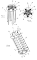
- FIG. 4 An alternative second embodiment achieving a similar effect is shown in figures 4 and 5 .
- This embodiment implements a transmission mechanism 40, which may be disposed at opposite ends or at one end only.
- the benefit of this embodiment as compared to the previous embodiment is on the one hand, that the curved slots 30 in the top and bottom plates 14, 15 may be avoided and that a transmission ratio between the speed of rotation of the rotor 10 about the axis of rotation 12 and the speed of rotation of the vanes 16 about the pivot axis 17 may be achieved.
- the transmission mechanism 40 comprises first gears 41 fixed to the vanes 16 concentric to the pivot axis 17 so that rotation of the first gears 41 results in a rotation of the vanes 16 about the pivot axis 17, respectively.
- the gears 41 are rotatably fixed to the top plate 14 of the rotor 10.
- second gears 42 are disposed meshing with the first gears 41 and rotatably fixed to the top plate 14 about an axis of rotation 43 parallel to the axis of rotation 12 and the pivot axis 17.
- Each of the second gears 42 has a cam follower 26 disposed concentric to the axis of rotation 43 but rotating together with the second gear 42.
- the cam followers 26 are constructed similar as the cam followers 26 shown in figures 2 and 3 each having an axis 29 and a wheel 27.
- a support 44 is fixed relative to the housing 18.
- the support 44 comprises a slotted guide 22 with an inner cam surface 24 and an outer cam surface 28 similar as in the first embodiment described above.
- the distance between the inner cam surface 24 and the parallel outer cam surface 27 to the axis of rotation 12 changes along the circumference.
- the cam followers 26 or more particularly their wheels 27 are pushed toward or away from the axis of rotation 12.
- the rotor 10 rotates relative to the support 44 and hence the slotted guide 22.
- the wheels 27 of the cam followers 26 move along the circumference of the slotted guide 22 and run along the cam surfaces 24 and 28 as in the first embodiment.
- the wheels 27 and hence the cam follower 26 are pushed away and towards the axis of rotation 12 whereby the second gears 42 are rotated. Because the second gears 42 mesh with the first gears 41, the rotation of the second gears 42 is transferred to the first gears 41.
- the vanes 16 are rotated by the rotation of the first gears 41 to assume the corresponding rotational position about the pivot axis 17 depending on the rotational position of the rotor as described in the first embodiment above.
- the rotational speed of the vanes 16 about the pivot axis 17 may be adjusted as needed.
- weakening of the top and bottom plates 14 and 15 because of the curved slots 30 in the first embodiment may be avoided by this construction.
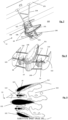
- a third embodiment which does not form part of the present invention and may be implemented isolated from or combined with the first and second embodiment described above, is shown in figure 6 .
- the rotor shown in figure 6 has a plurality of vanes 16 having protrusions 50 at opposite ends engaging with a curved cutout 51, the curve having the pivot axis 17 as a center.
- Opposite ends 52 of the cutout 51 serve as a limit stop to limit the angular range in which the vanes 16 may pivot, Baron the protrusion 50 abut at the ends 52 of the cutout 51 in the corresponding end positions of the angular range.
- a tension spring 53 is provided preferably at opposite ends of the vanes 17 in the axial direction.
- the tension springs 53 are fixed at one end 54 to the top or bottom plate 14, 15 respectively and at the opposite end 55 to the vanes 16 at a distance to the pivot axis 17. Thereby, the tension springs 53 force (urge) the vanes 16 into one rotational direction about the pivot axis 17 (in the present embodiment in a clockwise direction). This is the most simple construction of actively controlling the movement of the vanes 16, though it is only possible to control this movement in one rotational direction. Further, the springs may also be used to urge the vanes 17 in one direction and ensure secure engagement of the cam followers with the cam surface in other embodiments. Of course different solutions to urge the cam followers 26 against the cam surface may be used instead of these springs.
- a torsion spring may be used applying a torsion force to the vanes 16 at the pivot axis 17. Also in the first and/or second gears 42 may be urged by a torsion spring to urge the cam followers 26 into contact with the inner cam surface 24.
- Figure 6 embodies two of the devices described earlier wherein the housings 18 are visible in figures 6 and 7 .
- the system disclosed in these drawings comprises four rotors 10 which may have the configuration as described above, but which may also have a different construction with for example fixed vanes or vanes which are passively pivoting about the pivot axis.
- the construction of the rotor is not of significance with respect to this particular application and this particular application may also be embodied with different rotors 10.
- the floating body 101 is an intermediate floating body which fixed to the waterside 105 using a crossbar 104.
- An axis 106 at the end of the crossbar 104 opposite to the connection to the waterside 105 is fixed to the ground of the river by a support 107.
- the intermediate floating body 101 is rotatably supported by the axis of 106 so as to automatically adjust to the flow direction 13 of the liquid flow in the river 100.
- the longitudinal section of the floating bodies resembles an airfoil with airfoil surfaces 110 of the outer floating bodies 102, 103 facing airfoil surfaces 111 of the intermediate floating body 101.
- the facing surfaces 110 and 111 form a flow channel 112 having an inlet 113 upstream of the rotors 10 and an outlet 114 downstream of the rotors 10.
- the outer floating bodies 102, 103 are respectively fixed to the intermediate floating body 101 by arms 108 and 109 which are at opposite ends rotatably fixed to the outer floating bodies 102 and 103 and to the intermediate floating body 101.
- parallelograms are formed which by movement of the arms 108, 109 enable to adjust the inclination alpha of the airfoil surfaces 110 relative to the flow direction 13 and/or the airfoil surfaces 111 to adjust to the requirements of the river 100 particularly the flow rate of the liquid flow in the direction 13.
- the arms 108 may rotate so as to bring the outer floating bodies 102, 103 in front of the intermediate floating body 101 thereby closing the inlet 113, thus bringing the entire system into a non-operating position.
- the rotors 10 are protected from any liquid flowing through the rotors 10 so that for example during floods the rotors may be protected from being damaged by too high flow rates of the liquid flowing in the river 100 or from foreign matters being entrained in the river during those instances.
Landscapes
- Engineering & Computer Science (AREA)
- Power Engineering (AREA)
- Chemical & Material Sciences (AREA)
- Combustion & Propulsion (AREA)
- Mechanical Engineering (AREA)
- General Engineering & Computer Science (AREA)
- Other Liquid Machine Or Engine Such As Wave Power Use (AREA)
- Hydraulic Motors (AREA)
Claims (10)
- Vorrichtung zur Erzeugung von Elektrizität aus einem Flüssigkeitsstrom, umfassend:einen Rotor (10), der um eine Rotationsachse (12) drehbar ist; eine Vielzahl von Flügeln (16), die sich parallel zur Rotationsachse (12) erstrecken und am Rotor für gemeinsame Rotation mit dem Rotor befestigt sind, wobei jeder Flügel (16) um eine Schwenkachse (17) parallel zur Rotationsachse (12) innerhalb eines vorbestimmten beschränkten Winkelbereich schwenkbar ist, wobei ein Anschlag (52) bereitgestellt ist, an dem der Flügel (16) in einer Endposition anliegt, wobei die Schwenkachse (17) um einen Umfang des Rotor mit der Rotationsachse (12) als Mitte gleich beabstandet ist, wobei die Flügel (16) in mindestens einer Rotationsrichtung um die jeweiligen Schwenkachse (17) gezwungen werden, und die Flügel (16) jeweils einen Aktuator umfassen, der bei Rotation des Rotors (10) angetrieben wird und der so konfiguriert ist, dass er die Rotation des Rotors (10) auf den Flügel (16) überträgt, wodurch der Flügel (16) gezwungen wird, um die Schwenkachse (17) zu schwenken, dadurch gekennzeichnet, dassder Aktuator einen Nockenstößel (26) aufweist, das sich bei Rotation des Rotors (10) entlang einer Nockenoberfläche (24, 28) dreht, wobei sich der Abstand der Nockenoberfläche (24, 28) zur Rotationsachse (12) entlang der Bewegung des Nockenstößels (26) entlang der Nockenoberfläche (24, 28) ändert, um den Flügel (16) zu zwingen, um die Schwenkachse (17) zu schwenken.
- Vorrichtung nach Anspruch 1, wobei jeder Flügel (16) einen ersten Aktuator an einem ersten Ende des Flügel in einer Richtung parallel zur Rotationsachse (12) und einen zweiten Aktuator an einem zweiten Ende des Flügels in einer Richtung parallel zur Rotationsachse (12) gegenüberliegend zum ersten Ende aufweist.
- Vorrichtung nach Anspruch 1 oder 2, wobei die Nockenoberfläche (24, 28) durch eine Schlitzführung (22) gebildet ist.
- Vorrichtung nach einem der vorstehenden Ansprüche, wobei der Nockenstößel (26) ein drehbares Rad (27) ist, das entlang der Nockenoberfläche (24, 28) läuft.
- Vorrichtung nach einem der vorstehenden Ansprüche, wobei sich die Nockenoberfläche (24, 28) durchgehend um den Umfang des Rotors (10) mit dem sich entlang des Umfangs verändernden Abstand zwischen der Nockenoberfläche und der Rotationsachse (12) erstreckt.
- Vorrichtung nach einem der vorstehenden Ansprüche, wobei der Rotor (10) in Bezug auf die Nockenoberfläche (24, 28) dreht.
- Vorrichtung nach einem der vorstehenden Ansprüche, wobei der Aktuator als ein Hebelarm (25) fungiert, wobei eine Ende des Hebelarm mit dem Flügel (60) verbunden ist und das entgegengesetzte Ende, das angetrieben wird, den Nockenstößel (26) aufweist.
- Vorrichtung nach einem der Ansprüche 1 bis 6, wobei jeder Flügel (16) weiter ein Getriebe (40) umfasst, das den Aktuator umfasst.
- Vorrichtung mach Anspruch 8, wobei das Getriebe (40) weiter ein erstes Zahnrad (41) umfasst, das an einem Ende des Flügels (60) in einer Richtung parallel zur Rotationsachse (12) und koaxial zur Schwenkachse (17) montiert ist, wobei der Aktuator ein zweites Zahnrad (42) ist, das durch die Rotation des Rotors (10), der den Nockenstößel (26) aufweist, das exzentrisch auf dem zweiten Zahnrad angeordnet ist, angetrieben wird, wobei die Rotation des zweiten Zahnrads (42) auf das erste Zahnrad (41) übertragen wird, bevorzugt dadurch, dass das erste Zahnrad in das zweite Zahnrad eingreift.
- Vorrichtung nach einem der vorstehenden Ansprüche, wobei die Flügel (16) durch ein elastisches Element (53) in die Rotationsrichtung gedrängt werden.
Applications Claiming Priority (1)
| Application Number | Priority Date | Filing Date | Title |
|---|---|---|---|
| PCT/EP2015/063166 WO2016198120A1 (en) | 2015-06-12 | 2015-06-12 | Device for generating electricity from a liquid flow |
Publications (3)
| Publication Number | Publication Date |
|---|---|
| EP3308012A1 EP3308012A1 (de) | 2018-04-18 |
| EP3308012B1 true EP3308012B1 (de) | 2025-04-23 |
| EP3308012C0 EP3308012C0 (de) | 2025-04-23 |
Family
ID=53385652
Family Applications (1)
| Application Number | Title | Priority Date | Filing Date |
|---|---|---|---|
| EP15728537.0A Active EP3308012B1 (de) | 2015-06-12 | 2015-06-12 | Vorrichtung zur erzeugung von elektrizität aus einem flüssigkeitsstrom |
Country Status (2)
| Country | Link |
|---|---|
| EP (1) | EP3308012B1 (de) |
| WO (1) | WO2016198120A1 (de) |
Families Citing this family (4)
| Publication number | Priority date | Publication date | Assignee | Title |
|---|---|---|---|---|
| KR101884566B1 (ko) * | 2017-05-24 | 2018-08-01 | 최진영 | 접철식 수차날개를 갖는 수차 |
| FR3104191A1 (fr) * | 2019-12-06 | 2021-06-11 | Effipower | Dispositif rotatif de transformation de l’énergie |
| FR3121481B1 (fr) * | 2021-04-06 | 2024-10-25 | Adv Tech | Rotor à pales orientables |
| GB2606390B (en) * | 2021-05-06 | 2023-06-07 | Achelous Energy Ltd | Systems and devices for a floating renewable power station |
Citations (1)
| Publication number | Priority date | Publication date | Assignee | Title |
|---|---|---|---|---|
| EP3212924A1 (de) * | 2014-10-31 | 2017-09-06 | Gkinetic Energy Limited | Wasserturbinenanordnung |
Family Cites Families (4)
| Publication number | Priority date | Publication date | Assignee | Title |
|---|---|---|---|---|
| DE3026315A1 (de) * | 1980-07-11 | 1982-02-11 | Erich Herter | Windturbine |
| US4618312A (en) * | 1985-01-28 | 1986-10-21 | Williams Robert A | Wind operated apparatus |
| GB9004230D0 (en) * | 1990-02-24 | 1990-04-18 | Goodden John J P | Turbine or propulsion rotor with independently rotating blades |
| GB2495438B (en) * | 2010-12-30 | 2014-11-05 | Cameron Int Corp | A system for energy generation |
-
2015
- 2015-06-12 EP EP15728537.0A patent/EP3308012B1/de active Active
- 2015-06-12 WO PCT/EP2015/063166 patent/WO2016198120A1/en not_active Ceased
Patent Citations (1)
| Publication number | Priority date | Publication date | Assignee | Title |
|---|---|---|---|---|
| EP3212924A1 (de) * | 2014-10-31 | 2017-09-06 | Gkinetic Energy Limited | Wasserturbinenanordnung |
Also Published As
| Publication number | Publication date |
|---|---|
| WO2016198120A1 (en) | 2016-12-15 |
| EP3308012A1 (de) | 2018-04-18 |
| EP3308012C0 (de) | 2025-04-23 |
Similar Documents
| Publication | Publication Date | Title |
|---|---|---|
| EP3308012B1 (de) | Vorrichtung zur erzeugung von elektrizität aus einem flüssigkeitsstrom | |
| TWI647385B (zh) | 輪機 | |
| US9689368B2 (en) | Method and apparatus for energy generation | |
| JP2009542959A (ja) | 可変ピッチの翼を有する風力タービン | |
| US20100303613A1 (en) | Rotation device | |
| US4519742A (en) | Apparatus for utilizing the energy present in flowing water | |
| CN107002631A (zh) | 水涡轮机组件 | |
| JP5702781B2 (ja) | 波力潮汐発電プラントおよびその方法 | |
| KR20060035710A (ko) | 조류를 이용한 수차 | |
| EP2616673B1 (de) | Antriebsvorrichtung für einen Stromgenerator | |
| KR101637482B1 (ko) | 웜휠 및 구동링크로 개폐를 제어하는 가동보 | |
| US10634114B1 (en) | Multivane hydrokinetic turbine | |
| EP3483423B1 (de) | Luftturbine zur extraktion von energie aus schwingenden wassersäulenvorrichtungen | |
| KR20160011049A (ko) | 저수심 수력발전용 듀얼터빈 조립체 | |
| AU2017243431A1 (en) | Device for the continuous and discriminated positioning of each blade of hydraulic turbines at vertical axis | |
| WO2017096460A1 (en) | Wind turbine with hinged blades |
Legal Events
| Date | Code | Title | Description |
|---|---|---|---|
| STAA | Information on the status of an ep patent application or granted ep patent |
Free format text: STATUS: THE INTERNATIONAL PUBLICATION HAS BEEN MADE |
|
| PUAI | Public reference made under article 153(3) epc to a published international application that has entered the european phase |
Free format text: ORIGINAL CODE: 0009012 |
|
| STAA | Information on the status of an ep patent application or granted ep patent |
Free format text: STATUS: REQUEST FOR EXAMINATION WAS MADE |
|
| 17P | Request for examination filed |
Effective date: 20180112 |
|
| AK | Designated contracting states |
Kind code of ref document: A1 Designated state(s): AL AT BE BG CH CY CZ DE DK EE ES FI FR GB GR HR HU IE IS IT LI LT LU LV MC MK MT NL NO PL PT RO RS SE SI SK SM TR |
|
| AX | Request for extension of the european patent |
Extension state: BA ME |
|
| DAV | Request for validation of the european patent (deleted) | ||
| DAX | Request for extension of the european patent (deleted) | ||
| STAA | Information on the status of an ep patent application or granted ep patent |
Free format text: STATUS: EXAMINATION IS IN PROGRESS |
|
| 17Q | First examination report despatched |
Effective date: 20190227 |
|
| GRAP | Despatch of communication of intention to grant a patent |
Free format text: ORIGINAL CODE: EPIDOSNIGR1 |
|
| STAA | Information on the status of an ep patent application or granted ep patent |
Free format text: STATUS: GRANT OF PATENT IS INTENDED |
|
| INTG | Intention to grant announced |
Effective date: 20200507 |
|
| GRAJ | Information related to disapproval of communication of intention to grant by the applicant or resumption of examination proceedings by the epo deleted |
Free format text: ORIGINAL CODE: EPIDOSDIGR1 |
|
| STAA | Information on the status of an ep patent application or granted ep patent |
Free format text: STATUS: EXAMINATION IS IN PROGRESS |
|
| INTC | Intention to grant announced (deleted) | ||
| GRAP | Despatch of communication of intention to grant a patent |
Free format text: ORIGINAL CODE: EPIDOSNIGR1 |
|
| STAA | Information on the status of an ep patent application or granted ep patent |
Free format text: STATUS: GRANT OF PATENT IS INTENDED |
|
| INTG | Intention to grant announced |
Effective date: 20201023 |
|
| GRAJ | Information related to disapproval of communication of intention to grant by the applicant or resumption of examination proceedings by the epo deleted |
Free format text: ORIGINAL CODE: EPIDOSDIGR1 |
|
| STAA | Information on the status of an ep patent application or granted ep patent |
Free format text: STATUS: EXAMINATION IS IN PROGRESS |
|
| INTC | Intention to grant announced (deleted) | ||
| GRAP | Despatch of communication of intention to grant a patent |
Free format text: ORIGINAL CODE: EPIDOSNIGR1 |
|
| STAA | Information on the status of an ep patent application or granted ep patent |
Free format text: STATUS: GRANT OF PATENT IS INTENDED |
|
| INTG | Intention to grant announced |
Effective date: 20241125 |
|
| GRAS | Grant fee paid |
Free format text: ORIGINAL CODE: EPIDOSNIGR3 |
|
| GRAA | (expected) grant |
Free format text: ORIGINAL CODE: 0009210 |
|
| STAA | Information on the status of an ep patent application or granted ep patent |
Free format text: STATUS: THE PATENT HAS BEEN GRANTED |
|
| AK | Designated contracting states |
Kind code of ref document: B1 Designated state(s): AL AT BE BG CH CY CZ DE DK EE ES FI FR GB GR HR HU IE IS IT LI LT LU LV MC MK MT NL NO PL PT RO RS SE SI SK SM TR |
|
| REG | Reference to a national code |
Ref country code: GB Ref legal event code: FG4D |
|
| REG | Reference to a national code |
Ref country code: CH Ref legal event code: EP |
|
| REG | Reference to a national code |
Ref country code: IE Ref legal event code: FG4D |
|
| U01 | Request for unitary effect filed |
Effective date: 20250423 |
|
| U07 | Unitary effect registered |
Designated state(s): AT BE BG DE DK EE FI FR IT LT LU LV MT NL PT RO SE SI Effective date: 20250429 |
|
| PGFP | Annual fee paid to national office [announced via postgrant information from national office to epo] |
Ref country code: GB Payment date: 20250624 Year of fee payment: 11 |
|
| U20 | Renewal fee for the european patent with unitary effect paid |
Year of fee payment: 11 Effective date: 20250625 |
|
| PG25 | Lapsed in a contracting state [announced via postgrant information from national office to epo] |
Ref country code: ES Free format text: LAPSE BECAUSE OF FAILURE TO SUBMIT A TRANSLATION OF THE DESCRIPTION OR TO PAY THE FEE WITHIN THE PRESCRIBED TIME-LIMIT Effective date: 20250423 |
|
| PG25 | Lapsed in a contracting state [announced via postgrant information from national office to epo] |
Ref country code: NO Free format text: LAPSE BECAUSE OF FAILURE TO SUBMIT A TRANSLATION OF THE DESCRIPTION OR TO PAY THE FEE WITHIN THE PRESCRIBED TIME-LIMIT Effective date: 20250723 Ref country code: GR Free format text: LAPSE BECAUSE OF FAILURE TO SUBMIT A TRANSLATION OF THE DESCRIPTION OR TO PAY THE FEE WITHIN THE PRESCRIBED TIME-LIMIT Effective date: 20250724 |
|
| PG25 | Lapsed in a contracting state [announced via postgrant information from national office to epo] |
Ref country code: PL Free format text: LAPSE BECAUSE OF FAILURE TO SUBMIT A TRANSLATION OF THE DESCRIPTION OR TO PAY THE FEE WITHIN THE PRESCRIBED TIME-LIMIT Effective date: 20250423 |
|
| PG25 | Lapsed in a contracting state [announced via postgrant information from national office to epo] |
Ref country code: HR Free format text: LAPSE BECAUSE OF FAILURE TO SUBMIT A TRANSLATION OF THE DESCRIPTION OR TO PAY THE FEE WITHIN THE PRESCRIBED TIME-LIMIT Effective date: 20250423 |
|
| PG25 | Lapsed in a contracting state [announced via postgrant information from national office to epo] |
Ref country code: RS Free format text: LAPSE BECAUSE OF FAILURE TO SUBMIT A TRANSLATION OF THE DESCRIPTION OR TO PAY THE FEE WITHIN THE PRESCRIBED TIME-LIMIT Effective date: 20250723 |
|
| PG25 | Lapsed in a contracting state [announced via postgrant information from national office to epo] |
Ref country code: IS Free format text: LAPSE BECAUSE OF FAILURE TO SUBMIT A TRANSLATION OF THE DESCRIPTION OR TO PAY THE FEE WITHIN THE PRESCRIBED TIME-LIMIT Effective date: 20250823 |
|
| PG25 | Lapsed in a contracting state [announced via postgrant information from national office to epo] |
Ref country code: SM Free format text: LAPSE BECAUSE OF FAILURE TO SUBMIT A TRANSLATION OF THE DESCRIPTION OR TO PAY THE FEE WITHIN THE PRESCRIBED TIME-LIMIT Effective date: 20250423 |
|
| PG25 | Lapsed in a contracting state [announced via postgrant information from national office to epo] |
Ref country code: CZ Free format text: LAPSE BECAUSE OF FAILURE TO SUBMIT A TRANSLATION OF THE DESCRIPTION OR TO PAY THE FEE WITHIN THE PRESCRIBED TIME-LIMIT Effective date: 20250423 |
|
| PG25 | Lapsed in a contracting state [announced via postgrant information from national office to epo] |
Ref country code: SK Free format text: LAPSE BECAUSE OF FAILURE TO SUBMIT A TRANSLATION OF THE DESCRIPTION OR TO PAY THE FEE WITHIN THE PRESCRIBED TIME-LIMIT Effective date: 20250423 |
|
| REG | Reference to a national code |
Ref country code: CH Ref legal event code: H13 Free format text: ST27 STATUS EVENT CODE: U-0-0-H10-H13 (AS PROVIDED BY THE NATIONAL OFFICE) Effective date: 20260127 |
|
| PG25 | Lapsed in a contracting state [announced via postgrant information from national office to epo] |
Ref country code: MC Free format text: LAPSE BECAUSE OF FAILURE TO SUBMIT A TRANSLATION OF THE DESCRIPTION OR TO PAY THE FEE WITHIN THE PRESCRIBED TIME-LIMIT Effective date: 20250423 |
|
| PLBE | No opposition filed within time limit |
Free format text: ORIGINAL CODE: 0009261 |
|
| STAA | Information on the status of an ep patent application or granted ep patent |
Free format text: STATUS: NO OPPOSITION FILED WITHIN TIME LIMIT |
|
| REG | Reference to a national code |
Ref country code: CH Ref legal event code: L10 Free format text: ST27 STATUS EVENT CODE: U-0-0-L10-L00 (AS PROVIDED BY THE NATIONAL OFFICE) Effective date: 20260304 |
|
| 26N | No opposition filed |
Effective date: 20260126 |
|
| PG25 | Lapsed in a contracting state [announced via postgrant information from national office to epo] |
Ref country code: IE Free format text: LAPSE BECAUSE OF NON-PAYMENT OF DUE FEES Effective date: 20250612 |
|
| PG25 | Lapsed in a contracting state [announced via postgrant information from national office to epo] |
Ref country code: CH Free format text: LAPSE BECAUSE OF NON-PAYMENT OF DUE FEES Effective date: 20250630 |