EP3308076B1 - Procédé de commande pour le fonctionnement d'une chaudière de combustion - Google Patents
Procédé de commande pour le fonctionnement d'une chaudière de combustion Download PDFInfo
- Publication number
- EP3308076B1 EP3308076B1 EP16727494.3A EP16727494A EP3308076B1 EP 3308076 B1 EP3308076 B1 EP 3308076B1 EP 16727494 A EP16727494 A EP 16727494A EP 3308076 B1 EP3308076 B1 EP 3308076B1
- Authority
- EP
- European Patent Office
- Prior art keywords
- flue gas
- boiler
- control method
- flow
- upper limit
- Prior art date
- Legal status (The legal status is an assumption and is not a legal conclusion. Google has not performed a legal analysis and makes no representation as to the accuracy of the status listed.)
- Active
Links
Images


Classifications
-
- F—MECHANICAL ENGINEERING; LIGHTING; HEATING; WEAPONS; BLASTING
- F23—COMBUSTION APPARATUS; COMBUSTION PROCESSES
- F23C—METHODS OR APPARATUS FOR COMBUSTION USING FLUID FUEL OR SOLID FUEL SUSPENDED IN A CARRIER GAS OR AIR
- F23C10/00—Fluidised bed combustion apparatus
- F23C10/18—Details; Accessories
- F23C10/28—Control devices specially adapted for fluidised bed, combustion apparatus
-
- F—MECHANICAL ENGINEERING; LIGHTING; HEATING; WEAPONS; BLASTING
- F23—COMBUSTION APPARATUS; COMBUSTION PROCESSES
- F23C—METHODS OR APPARATUS FOR COMBUSTION USING FLUID FUEL OR SOLID FUEL SUSPENDED IN A CARRIER GAS OR AIR
- F23C10/00—Fluidised bed combustion apparatus
- F23C10/18—Details; Accessories
- F23C10/22—Fuel feeders specially adapted for fluidised bed combustion apparatus
-
- F—MECHANICAL ENGINEERING; LIGHTING; HEATING; WEAPONS; BLASTING
- F23—COMBUSTION APPARATUS; COMBUSTION PROCESSES
- F23N—REGULATING OR CONTROLLING COMBUSTION
- F23N1/00—Regulating fuel supply
- F23N1/02—Regulating fuel supply conjointly with air supply
- F23N1/022—Regulating fuel supply conjointly with air supply using electronic means
-
- F—MECHANICAL ENGINEERING; LIGHTING; HEATING; WEAPONS; BLASTING
- F23—COMBUSTION APPARATUS; COMBUSTION PROCESSES
- F23N—REGULATING OR CONTROLLING COMBUSTION
- F23N3/00—Regulating air supply or draught
- F23N3/002—Regulating air supply or draught using electronic means
-
- F—MECHANICAL ENGINEERING; LIGHTING; HEATING; WEAPONS; BLASTING
- F23—COMBUSTION APPARATUS; COMBUSTION PROCESSES
- F23N—REGULATING OR CONTROLLING COMBUSTION
- F23N5/00—Systems for controlling combustion
- F23N5/003—Systems for controlling combustion using detectors sensitive to combustion gas properties
- F23N5/006—Systems for controlling combustion using detectors sensitive to combustion gas properties the detector being sensitive to oxygen
-
- F—MECHANICAL ENGINEERING; LIGHTING; HEATING; WEAPONS; BLASTING
- F23—COMBUSTION APPARATUS; COMBUSTION PROCESSES
- F23C—METHODS OR APPARATUS FOR COMBUSTION USING FLUID FUEL OR SOLID FUEL SUSPENDED IN A CARRIER GAS OR AIR
- F23C2900/00—Special features of, or arrangements for combustion apparatus using fluid fuels or solid fuels suspended in air; Combustion processes therefor
- F23C2900/10001—Use of special materials for the fluidized bed
-
- F—MECHANICAL ENGINEERING; LIGHTING; HEATING; WEAPONS; BLASTING
- F23—COMBUSTION APPARATUS; COMBUSTION PROCESSES
- F23N—REGULATING OR CONTROLLING COMBUSTION
- F23N2237/00—Controlling
- F23N2237/18—Controlling fluidized bed burners
-
- F—MECHANICAL ENGINEERING; LIGHTING; HEATING; WEAPONS; BLASTING
- F23—COMBUSTION APPARATUS; COMBUSTION PROCESSES
- F23N—REGULATING OR CONTROLLING COMBUSTION
- F23N2900/00—Special features of, or arrangements for controlling combustion
Definitions
- the invention is in the field of combustion boilers, in particular fluidized bed boilers, such as circulating fluidized bed (CFB) boilers, and relates to a control method for the operation of a boiler for the combustion of fuel and to a control system for a boiler for combusting fuel.
- Combustion boilers are known in the prior art. These boilers burn fuel, such as for example biomass fuel, waste-based fuel or coal, not excluding others. Typical examples for combustion boilers are grate boilers and fluidized bed boilers.
- FBC fluidized bed combustion
- the fuel is suspended in a hot bed of solid particulate material, typically silica sand, which is fluidized by passing a fluidization gas through the bed material.
- the fluidization gas is passed through the bed material forming bubbles in the bed, facilitating the transport of the gas through the bed material and allowing for a better control of the combustion conditions(better mixing and hence more even temperature distribution in the bed) when compared with grate combustion.
- CFB circulating fluidized bed
- the fluidization gas is passed through the bed material such that the major part of the bed particles become entrained in the fluidization gas so that they are carried away by the fluidization gas stream. The particles are then separated from the gas stream and circulated back into the furnace.
- Combustion boilers are known, for instance, from US 3,964,675 , US 2004/237909 A1 , or US 2013/323654 A1 .
- US 3,964,675 provides a basis for the two-part form of claim 1.
- the combustion conditions in particular the mixing of oxygen and fuel, are not ideal and for all boilers it is necessary to supply oxygen in excess of the amount required by stoichiometry in order to achieve essentially complete combustion.
- the chemical composition of the fuel determines the required oxygen flow into the furnace per mass unit fuel and the oxygen to fuel ratios required to burn a given fuel depend strongly on the type and composition of the fuel and in particular on the fuel's heterogeneity.
- typical fuels are biomass, waste and coal, with the former two being known to be rather inhomogeneous and thus requiring higher amounts of oxygen.
- the excess air ratios required are dependent on the type of the boiler used, e.g. pulverized combustion boilers, grates and fluidized bed boilers.
- the composition of the fuel determines the air flow into the furnace per mass unit fuel and the oxygen concentration in the flue gas is used to balance variations in the fuel composition during the boiler operation. If the composition of the fuel varies during boiler operation, the oxygen concentration in the flue gas, after the combustion zone, varies accordingly. The oxygen concentration can then be used in the control method to adjust the air to fuel ratio with the goal to maintain a constant pre-set oxygen concentration in the flue gas and thereby to arrive at a low emission of organic compounds and high boiler efficiency.
- the object of the invention is to provide a method for operating a combustion boiler which facilitates flexible and safe boiler operation.
- ilmenite as fluidized bed material in the CFB process ( H. Thunman et al., Fuel 113 (2013) 300-309 ).
- the naturally occurring mineral ilmenite is an iron titanium oxide (FeTiO 3 ) which can be repeatedly oxidized and reduced and thus acts as a redox material. Due to this reducing-oxidizing feature of ilmenite, the material can be utilized as an oxygen carrier in fluidized bed combustion.
- the ilmenite particles facilitate the mixing of oxygen and fuel and allow to carry out the combustion with less excess oxygen that is at a lower air to fuel ratio.
- a lower air to fuel ratio can be either achieved by decreasing the oxygen flow for a given fuel flow or by increasing the fuel load for a given oxygen flow.
- the latter approach allows to increase the thermal load (thermal output per unit time) of the boiler and thus permits to operate the boiler at higher thermal load and low excess air.
- the invention has recognized that a potential problem with this approach is that an increase in the fuel flow leads to an increase in the flue gas velocity. Every boiler design has a maximum flue gas velocity which should not be exceeded in order to avoid problems such as fouling, corrosion, erosion, etc.
- the invention has further recognized that existing control methods relying chiefly on the air to fuel ratio do not allow to safely increase the thermal load under low excess oxygen conditions, as there is the risk of inadvertently exceeding the design value for the maximum flue gas velocity.
- the invention provides a control method for the operation of a combustion boiler, comprising:
- the invention has recognized that this method provides an additional handle on the thermal load setting based on the flue gas velocity and thereby facilitates safe and flexible boiler operation.
- the boiler can be safeguarded against operation above a maximum allowed value for the flue gas velocity.
- the inventive method allows to safely operate the boiler at or even outside of the design specifications, in particular with increased thermal load under low excess oxygen conditions.
- the inventive method comprises providing a predetermined upper limit (V F,max ) for the flue gas velocity in at least one location of the boiler.
- flue gas velocity (V F ) denotes the velocity of the flue gas after the combustion zone.
- the flue gas comprises various components, e.g. the gas generated from the reaction between the fuel and the oxygen supplied to the furnace, any re-circulated flue gas, secondary air supplied and water and air added to the flue gas treatment plant downstream the boiler.
- Every boiler design has a design value (V F,design ) for the flue gas velocity for one or more locations in the boiler.
- the design value denotes a maximum velocity that should not be exceeded.
- the design value can for example be learned from the design specifications of the boiler in the boiler documentation.
- the predetermined upper limit (V F,max ) for the flue gas velocity is smaller than or equal to the design value (V F,design ) for the flue gas velocity in the respective location of the boiler.
- the predetermined upper limit (V F,max ) for the flue gas velocity is equal to the design value (V F,design ) for the flue gas velocity of the boiler. This allows to safely operate the boiler at the specified design limit.
- the predetermined upper limit (V F,max ) for the flue gas velocity it is also possible for the predetermined upper limit (V F,max ) for the flue gas velocity to be larger than the design value (V F,design ) for the flue gas velocity in the respective location of the boiler. Since the design specifications are often given with a safety margin in mind, in this preferred embodiment it becomes possible to operate the boiler outside of the design specifications.
- the inventive method further comprises monitoring the flue gas velocity (V F ) during the combustion of fuel.
- V F flue gas velocity
- the flue gas velocity can be determined by the skilled person in any location of the flue gas duct after the combustion zone according to the above formula.
- a preferred location is the duct upstream of the convective heat exchanger tube bundles. Temperature and pressure measurements should be available.
- the cross-sectional area is different in different parts of the boiler and the flue gas velocity is different in different parts of the boiler.
- the design value (V F,design ) for the flue gas velocity is generally given by the boiler supplier in the boiler documentation for various locations of the flue gas duct.
- the flue gas velocity (V F ) can be determined for one or more of these locations. It is generally sufficient to determine the flue gas velocity (V F ) in one location and compare it to the corresponding predetermined upper limit (V F,max ), since all flue gas velocities are interrelated.
- the volume flow of flue gas V C can be calculated following the European Standard EN 12952-15. Alternatively, the volume flow of flue gas V C can be determined from measurement.
- the total gas flow can be measured by differential pressure using a Prandtl tube located in the flue gas duct at the stack.
- the flow of recirculated flue gas can be measured by differential pressure using a Prandtl tube located downstream the recirculation gas fan.
- the air flow to the flue gas cleaning equipment can be measured by means of the fan curve, which describes the characteristics of the fan.
- the gas temperature Tc can be measured in situ by a thermocouple.
- the pressure Pc, in the specified location can be measured by subtracting the pressure drop of the super-heater tube banks from the absolute pressure measured upstream of the economizer.
- the inventive method further comprises comparing the flue gas velocity (V F ) with the predetermined upper limit (V F,max ) for the flue gas velocity in the respective location of the boiler and decreasing the thermal load of the boiler if the flue gas velocity exceeds the predetermined upper limit (V F,max ) for the flue gas velocity.
- the predetermined upper limit is equal to the design value for the flue gas velocity.
- the thermal load is decreased to reduce the flue gas velocity (V F ) below the predetermined upper limit (V F,max ).
- the thermal load is decreased until the flue gas velocity (V F ) is below the predetermined upper limit (V F,max ).
- the thermal load can be decreased continuously or in increments. It is particularly preferred to decrease the thermal load by decreasing the mass flow of the fuel into the furnace of the boiler.
- control method also comprises:
- the fuel flow rate can preferably be determined by measuring the speed of the fuel feeders.
- the thermal load produced by the boiler is a standard output, which is routinely measured. It can be calculated by multiplying the measured steam (or feedwater) flow with the enthalpy difference between the feedwater and the steam, both derived from the measured temperature and pressure of the feedwater and steam.
- control method further comprises:
- the oxygen concentration in the flue gas is a commonly measured parameter in commercial boilers. It may typically be measured by an in-situ located lambda probe (zirconia cell) or by using paramagnetic sensors.
- the skilled person can select suitable upper and lower limits for the oxygen concentration in the flue gas for any given fuel type. Usually suggested ranges are provided by the boiler supplier in the boiler documentation.
- the lower limit and the upper limit for the oxygen concentration in the flue gas may be set to the same value. In this case, the oxygen concentration can essentially be kept at a setpoint value.
- the inventive method may advantageously provide for an operator to manually adjust the thermal load and/or the air flow into the furnace and/or the fuel flow into the furnace (so called manual handle). This allows to override or adjust the control loops based on expert decision.
- manual adjustments may be an increase or a decrease of the thermal load and/or the air flow into the furnace and/or the fuel flow into the furnace by less than 20%, preferably less than 15%, most preferably less than 10%.
- the boiler can be a fluidized bed boiler, more preferably a bubbling fluidized bed (BFB) boiler or a circulating fluidized bed (CFB) boiler.
- BFB boilers are particularly preferred in the context of the invention.
- the bed material of the fluidized bed boiler comprises ilmenite particles. In a particularly preferred embodiment, the bed material consists of ilmenite particles.
- oxygen is supplied to the furnace of the boiler via oxygen containing gas, most preferably air.
- the invention also relates to a control system for a combustion boiler, comprising means for monitoring the flue gas velocity (VF) during the combustion of fuel in at Least one location of the boiler, and means for decreasing the thermal load of the boiler, wherein the control system is configured to execute the control method described above.
- the boiler can be a fluidized bed boiler, more preferably a bubbling fluidized bed (BFB) boiler or a circulating fluidized bed (CFB) boiler.
- BFB boilers are particularly preferred in the context of the invention.
- the bed material of the fluidized bed boiler comprises ilmenite particles. In a particularly preferred embodiment, the bed material consists of ilmenite particles.
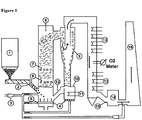
- Fig. 1 shows a typical CFB boiler, which can be controlled by the inventive method.
- the reference numerals denote:
- Fuel is stored in the fuel bunker (1) and can be fed to the furnace (8) via a fuel chute (2).
- the fluidization gas in this case air
- the fluidization gas is fed to the furnace (8) as primary combustion air via the primary air distributor (5) from below the bed and passed through the bed material so that the majority of solid particles (bed material, fuel and ash particles) are carried away by the fluidization gas stream.
- the particles are then separated from the gas stream using a cyclone (9) and circulated back into the furnace (8) via a loop seal (10).
- Additional combustion air is fed into the furnace to enhance the mixing of oxygen and fuel.
- Secondary air refers to all oxygen containing gas fed into the furnace for the combustion of fuel which is not primary fluidizing gas.
- secondary air ports (6) are located throughout the furnace, in particular the freeboard (the part of the furnace above the dense bottom bed).
- the flue gas is passed through the flue gas treatment plant (14) for post treatment and the treated flue gas escapes through the stack (16). A portion of the flue gas may be recirculated to the furnace as indicated in Fig. 1 .
- a CFB boiler as shown in Fig. 1 is operated with silica sand particles as bed material and controlled by controlling the air to fuel ratio.
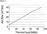
- a predetermined relationship between the oxygen flow (here air flow) into the furnace of the boiler and the thermal load is provided for the fuel type utilized as shown in Fig. 2 .
- the thermal load produced by the boiler is measured and the air flow into the furnace is adjusted based on the predetermined relationship between the air flow and the thermal load as well as the actual oxygen concentration in the flue gas.
- a predetermined lower limit and a predetermined upper limit are set for the oxygen concentration in the flue gas and the oxygen concentration in the flue gas during combustion is monitored.
- the oxygen concentration in the flue gas is compared with the predetermined upper limit and the predetermined lower limit for the oxygen concentration and the flow of oxygen into the furnace is adjusted by
- the lower limit and the upper limit for the oxygen concentration in the flue gas may be set to the same value.
- the oxygen concentration can essentially be kept at a setpoint value.
- a CFB boiler as shown in Fig. 1 is operated with ilmenite particles as bed material and controlled by the inventive control method.
- V F,max is set to the design value (V F,design ) for the flue gas velocity for the boiler, with V F,design taken from the design specifications.
- A is taken from the design specifications or obtained by actual measurement of the cross section.
- the total gas flow is measured by differential pressure using a Prandtl tube located in the flue gas duct at the stack.
- the flow of recirculated flue gas is measured by differential pressure using a Prandtl tube located downstream the recirculation gas fan.
- the air flow to the flue gas cleaning equipment is measured by means of the fan curve, which describes the characteristics of the fan.
- the gas temperature Tc is measured in situ by a thermocouple.
- the pressure Pc, in the specified location is measured by subtracting the pressure drop of the super-heater tube banks from the absolute pressure measured upstream of the economizer.
- the thermal load is decreased either continuously or in increments to reduce the flue gas velocity (V F ) below the predetermined upper limit (V F,max ) .
- the thermal load is decreased by decreasing the mass flow of the fuel into the furnace of the boiler.
- a predetermined relationship between the oxygen flow (here air flow) into the furnace of the boiler and the thermal load is provided for the fuel type utilized as shown in Fig. 2 .
- the thermal load produced by the boiler is measured and the air flow into the furnace is adjusted based on the predetermined relationship between the air flow and the thermal load as well as the actual oxygen concentration in the flue gas.
- a predetermined lower limit and a predetermined upper limit are set for the oxygen concentration in the flue gas and the oxygen concentration in the flue gas during combustion is monitored.
- the oxygen concentration in the flue gas is compared with the predetermined upper limit and the predetermined lower limit for the oxygen concentration and the air flow into the furnace is adjusted by
- the lower limit and the upper limit for the oxygen concentration in the flue gas may be set to the same value.
- the oxygen concentration can essentially be kept at a setpoint value.
- FIG. 4 A control system implementing this inventive method is schematically shown in Figure 4 .
- the flue gas velocity has been determined in a commercially fired CFB boiler operated with ilmenite particles as bed material.
- the flue gas velocity has been calculated from the volume flow of flue gas divided by the cross-sectional area of the flue gas duct in the location just downstream the cyclone, wherein the volume flow of the flue gas was determined according to the formula in Example 1.
- the measured flue gas velocity (in m/s) is shown in Fig. 5 together with the measured pressure drop (in kPa) as a function of time for the CFB boiler.
- the pressure drop is the total pressure drop from the furnace to the suction side of the induced draught fan (the flue gas fan).
- the flue gas velocity is a very good indicator on the pressure drop during normal operation, as can be seen from Fig. 5 , where no lagging between the signals can be seen. If the boiler gets fouled the relationship between the pressure drop and the gas velocity gets affected.
- Figure 5 proves that the flue gas velocity is a suitable control parameter.
Landscapes
- Engineering & Computer Science (AREA)
- Chemical & Material Sciences (AREA)
- Combustion & Propulsion (AREA)
- Mechanical Engineering (AREA)
- General Engineering & Computer Science (AREA)
- Regulation And Control Of Combustion (AREA)
- Fluidized-Bed Combustion And Resonant Combustion (AREA)
Claims (15)
- Procédé de commande pour le fonctionnement d'une chaudière à combustion, comportant les étapes consistant à :a) mettre en place une limite supérieure prédéterminée (VF,max) pour la vitesse de gaz d'évacuation à au moins un emplacement de la chaudière ;b) surveiller la vitesse de gaz d'évacuation (VF) pendant la combustion d'un combustible dans ledit ou lesdits emplacements de la chaudière ;c) comparer la vitesse de gaz d'évacuation (VF) avec la limite supérieure prédéterminée (VF,max) ;
caractérisé en ce que le procédé comporte en outre l'étape consistant à :d) diminuer la charge thermique de la chaudière si la vitesse de gaz d'évacuation dépasse la limite supérieure prédéterminée (VF,max). - Procédé de commande selon la revendication 1, la charge thermique étant diminuée pour réduire la vitesse de gaz d'évacuation (VF) au-dessous de la limite supérieure prédéterminée (VF,max).
- Procédé de commande selon la revendication 1 ou la revendication 2, caractérisé en ce que la charge thermique est diminuée jusqu'à ce que la vitesse de gaz d'évacuation (VF) soit au-dessous de la limite supérieure prédéterminée (VF,max), la diminution étant de préférence une diminution continue, idéalement une diminution incrémentale.
- Procédé de commande selon l'une quelconque des revendications 1 à 3, la charge thermique étant diminuée en diminuant le débit massique du combustible entrant dans le foyer de la chaudière.
- Procédé de commande selon l'une quelconque des revendications 1 à 4, la limite supérieure prédéterminée (VF,max) pour la vitesse de gaz d'évacuation étant inférieure ou égale à la valeur de conception (VF,design) pour la vitesse de gaz d'évacuation pour la chaudière.
- Procédé de commande selon la revendication 5, la limite supérieure prédéterminée (VF,max) pour la vitesse de gaz d'évacuation étant égale à la valeur de conception (VF,design) pour la vitesse de gaz d'évacuation pour la chaudière.
- Procédé de commande selon l'une quelconque des revendications 1 à 6, comportant en outre les étapes consistant à :e) mettre en place- une relation prédéterminée entre le débit d'air et le débit de combustible entrant dans le foyer de la chaudière ; et/ou- une relation prédéterminée entre le débit d'air entrant dans le foyer de la chaudière et la charge thermique ;f) mesurer le débit de combustible entrant dans le foyer de la chaudière et/ou la charge thermique ;g) régler le débit d'air entrant dans le foyer sur la base de la relation prédéterminée mise en place à l'étape e) et du débit mesuré de combustible entrant dans la chaudière et/ou de la charge thermique mesurée.
- Procédé de commande selon l'une quelconque des revendications 1 à 7, comportant en outre les étapes consistant à :h) spécifier une limite inférieure prédéterminée et une limite supérieure prédéterminée pour la concentration d'oxygène dans le gaz d'évacuation ;i) surveiller la concentration d'oxygène dans le gaz d'évacuation pendant la combustion ;j) comparer la concentration d'oxygène dans le gaz d'évacuation avec la limite supérieure prédéterminée et la limite inférieure prédéterminée pour la concentration d'oxygène dans le gaz d'évacuation ;k) régler le débit d'air entrant dans le foyer- en augmentant le débit d'air entrant dans le foyer si la concentration d'oxygène dans le gaz d'évacuation est au-dessous de la limite inférieure ; et- en diminuant le débit d'air entrant dans le foyer si la concentration d'oxygène dans le gaz d'évacuation est au-dessus de la limite supérieure.
- Procédé de commande selon l'une quelconque des revendications 1 à 8, la chaudière étant une chaudière à lit fluidisé, de préférence choisie dans le groupe constitué des chaudières à lit fluidisé bouillonnant et des chaudières à lit fluidisé circulant.
- Procédé de commande selon la revendication 9, le matériau de lit de la chaudière à lit fluidisé comportant des particules d'ilménite.
- Procédé de commande selon la revendication 10, le matériau de lit étant constitué de particules d'ilménite.
- Procédé de commande selon l'une quelconque des revendications 1 à 11, la vitesse de gaz d'évacuation (VF) étant déterminée selon la formule suivante :
 V̇c = débit volumique de gaz d'évacuation ;A = aire en section droite du conduit de gaz d'évacuation.
 - Procédé de commande selon la revendication 12, la chaudière étant une chaudière à lit fluidisé circulant (LFC) et la vitesse de gaz d'évacuation étant déterminée pour la région adjacente au cyclone et en aval de celui-ci, et le débit volumique de gaz d'évacuation étant déterminé selon la formule suivante :
 V̇Total,stack = débit total de gaz dans la cheminée
 V̇FGR = débit de gaz d'évacuation recyclé
 V̇Air,FGT = débit d'air ajouté à l'installation de traitement de gaz d'évacuation
 V̇Water vapour,FGT = débit de vapeur d'eau issu de l'eau ajoutée à l'installation de traitement de gaz d'évacuation
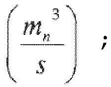 Tc = température immédiatement en aval du cyclone (°C) ;Pc = pression immédiatement en aval du cyclone (Pa),le débit de vapeur d'eau dans l'installation de traitement de gaz d'évacuation étant déterminé comme le débit massique d'eau ajoutée divisé par la densité de la vapeur d'eau.
 - Système de commande pour une chaudière à combustion, comportant un moyen servant à surveiller la vitesse de gaz d'évacuation (VF) pendant la combustion d'un combustible dans au moins un emplacement de la chaudière, et un moyen servant à diminuer la charge thermique de la chaudière, le système de commande étant configuré pour exécuter le procédé de commande selon l'une quelconque des revendications 1 à 6.
- Système de commande selon la revendication 14, la chaudière étant une chaudière à lit fluidisé, de préférence choisie dans le groupe constitué des chaudières à lit fluidisé bouillonnant et des chaudières à lit fluidisé circulant.
Priority Applications (1)
| Application Number | Priority Date | Filing Date | Title |
|---|---|---|---|
| PL16727494T PL3308076T3 (pl) | 2015-06-15 | 2016-06-07 | Sposób sterowania dla eksploatacji kotła spalinowego |
Applications Claiming Priority (3)
| Application Number | Priority Date | Filing Date | Title |
|---|---|---|---|
| EP15172218 | 2015-06-15 | ||
| EP15173894.5A EP3106747A1 (fr) | 2015-06-15 | 2015-06-25 | Procede de commande pour le fonctionnement d'une chaudiere a combustion |
| PCT/EP2016/062886 WO2016202640A1 (fr) | 2015-06-15 | 2016-06-07 | Procédé de commande pour le fonctionnement d'une chaudière de combustion |
Publications (2)
| Publication Number | Publication Date |
|---|---|
| EP3308076A1 EP3308076A1 (fr) | 2018-04-18 |
| EP3308076B1 true EP3308076B1 (fr) | 2020-11-18 |
Family
ID=53476693
Family Applications (2)
| Application Number | Title | Priority Date | Filing Date |
|---|---|---|---|
| EP15173894.5A Withdrawn EP3106747A1 (fr) | 2015-06-15 | 2015-06-25 | Procede de commande pour le fonctionnement d'une chaudiere a combustion |
| EP16727494.3A Active EP3308076B1 (fr) | 2015-06-15 | 2016-06-07 | Procédé de commande pour le fonctionnement d'une chaudière de combustion |
Family Applications Before (1)
| Application Number | Title | Priority Date | Filing Date |
|---|---|---|---|
| EP15173894.5A Withdrawn EP3106747A1 (fr) | 2015-06-15 | 2015-06-25 | Procede de commande pour le fonctionnement d'une chaudiere a combustion |
Country Status (5)
| Country | Link |
|---|---|
| US (1) | US11060719B2 (fr) |
| EP (2) | EP3106747A1 (fr) |
| CN (1) | CN107750320B (fr) |
| PL (1) | PL3308076T3 (fr) |
| WO (1) | WO2016202640A1 (fr) |
Families Citing this family (13)
| Publication number | Priority date | Publication date | Assignee | Title |
|---|---|---|---|---|
| EP3106531A1 (fr) | 2015-06-15 | 2016-12-21 | Improbed AB | Utilisation d'ilménite pré-oxydée dans des chaudières à lit fluidisé |
| EP3106747A1 (fr) | 2015-06-15 | 2016-12-21 | Improbed AB | Procede de commande pour le fonctionnement d'une chaudiere a combustion |
| WO2016202641A1 (fr) | 2015-06-15 | 2016-12-22 | Improbed Ab | Procédé pour faire fonctionner une chaudière à lit fluidisé |
| CN107327839B (zh) * | 2017-08-16 | 2023-08-18 | 吉林大学 | 一种循环流化床锅炉降氧抑氮系统及控制方法 |
| RU2686130C1 (ru) * | 2018-05-14 | 2019-04-24 | Общество с ограниченной ответственностью "ТЕПЛОМЕХ" | Котел малой мощности высокотемпературного кипящего слоя с системой автоматического регулирования процесса горения |
| RU2680778C1 (ru) * | 2018-05-22 | 2019-02-26 | Общество с ограниченной ответственностью "ТЕПЛОМЕХ" | Система автоматического регулирования процесса горения в котлоагрегате для сжигания твердого топлива в кипящем слое |
| RU2686238C1 (ru) * | 2018-06-04 | 2019-04-24 | Общество с ограниченной ответственностью "ТЕПЛОМЕХ" | Система автоматического регулирования процесса горения силовой установки с активным котлом-утилизатором высокотемпературного кипящего слоя |
| RU2709591C1 (ru) * | 2018-08-22 | 2019-12-18 | Ооо "Тепломех" | Силовая установка с активным котлом утилизатором высокотемпературного кипящего слоя с улучшенными характеристиками топочных процессов |
| RU2709592C1 (ru) * | 2018-08-22 | 2019-12-18 | Общество с ограниченной ответственностью "ТЕПЛОМЕХ" | Силовая установка с активным котлом-утилизатором высокотемпературного кипящего слоя, устройством очистки уходящих газов и узлом смешения газов |
| FI129372B (fi) * | 2019-06-28 | 2022-01-14 | Andritz Oy | Soodakattilan savukaasun yhden tai useamman suhteellisen partikkeliryhmäosuuden määritys |
| US11486576B2 (en) * | 2019-08-23 | 2022-11-01 | Regal Beloit America, Inc. | System and method for burner ignition using sensorless constant mass flow draft inducers |
| CN110887038B (zh) * | 2019-12-26 | 2021-05-28 | 哈尔滨中远控制工程有限公司 | 一种循环流化床锅炉燃烧自适应控制系统及方法 |
| HUE073502T2 (hu) | 2021-09-09 | 2026-01-28 | Sumitomo SHI FW Energia Oy | Kazánvezérlési eljárás, kazán és kazánvezérlési rendszer |
Family Cites Families (33)
| Publication number | Priority date | Publication date | Assignee | Title |
|---|---|---|---|---|
| DE2024907C3 (de) | 1970-05-22 | 1978-07-06 | Bayer Ag, 5090 Leverkusen | Verfahren zur Herstellung von Titandioxidkonzentraten aus ilmenithaltigen Materialien |
| US3785204A (en) * | 1972-04-06 | 1974-01-15 | Exxon Research Engineering Co | Mass flow meter |
| US3964675A (en) * | 1974-10-15 | 1976-06-22 | Euchner Jr Perry C | Appartus for limiting vacuum and pressure in a furnace |
| NZ196064A (en) | 1980-01-22 | 1986-01-24 | Commw Scient Ind Res Org | Wood distillation in fluidised bed |
| US4843981A (en) | 1984-09-24 | 1989-07-04 | Combustion Power Company | Fines recirculating fluid bed combustor method and apparatus |
| EP0185931B1 (fr) | 1984-12-25 | 1991-07-24 | Ebara Corporation | Procédé et appareil pour le traitement de déchets |
| AU7029887A (en) | 1986-02-14 | 1987-09-09 | Ebara Corporation | Fluidized-bed method for burning combustible materials |
| EP0411133B1 (fr) * | 1988-10-20 | 1994-08-24 | Ebara Corporation | Installation de combustion et procede de regulation de combustion |
| JP2530913B2 (ja) * | 1989-05-24 | 1996-09-04 | 東京瓦斯株式会社 | バ―ナに於ける燃料ガスと燃焼用空気の供給機構及び供給装置 |
| DE4007635C1 (fr) | 1990-03-10 | 1991-09-19 | Vereinigte Kesselwerke Ag, 4000 Duesseldorf, De | |
| US5954000A (en) * | 1997-09-22 | 1999-09-21 | Combustion Engineering, Inc. | Fluid bed ash cooler |
| TW419574B (en) | 1998-06-16 | 2001-01-21 | Mitsubishi Heavy Ind Ltd | Operating method of flow-level incinerator and the incinerator |
| JP2002543268A (ja) * | 1999-05-04 | 2002-12-17 | コモンウェルス サイエンティフィック アンド インダストリアル リサーチ オーガニゼーション | 木材残渣を炭化して活性炭を製造する方法 |
| US6532905B2 (en) * | 2001-07-17 | 2003-03-18 | The Babcock & Wilcox Company | CFB with controllable in-bed heat exchanger |
| AU2003284119A1 (en) * | 2002-10-30 | 2004-06-07 | Krebs And Sisler Lp | A method and apparatus to conduct oxygen-enriched combustion |
| CN1210517C (zh) * | 2003-12-12 | 2005-07-13 | 东南大学 | 燃气循环流化床间接燃烧装置及方法 |
| EP2031960A4 (fr) * | 2006-06-15 | 2014-03-26 | Woodstream Corp | Dispositif pour piéger des insectes volants et système de piège pour insectes volants |
| CN101650566B (zh) * | 2009-09-14 | 2011-08-17 | 清华大学 | 催裂化装置常规再生的再生烟气成份动态软测量方法 |
| JP2011112030A (ja) * | 2009-11-30 | 2011-06-09 | Ntn Corp | ガス供給装置および排ガス発電システム |
| EP2361667B1 (fr) * | 2010-02-25 | 2015-04-01 | Alstom Technology Ltd | Épurateur par voie humide et procédé de nettoyage d'un gaz de procédé |
| CN101915428A (zh) * | 2010-08-23 | 2010-12-15 | 张云斌 | 一种硬质炭黑生产节能装置及其生产方法 |
| CN102453792B (zh) * | 2010-10-26 | 2013-07-17 | 宝山钢铁股份有限公司 | 连续退火炉炉压控制方法及控制设备 |
| FI124100B (fi) * | 2011-01-24 | 2014-03-14 | Endev Oy | Menetelmä kiertomassareaktorin toiminnan parantamiseksi ja menetelmän toteuttava kiertomassareaktori |
| WO2012124062A1 (fr) * | 2011-03-15 | 2012-09-20 | トヨタ自動車株式会社 | Dispositif de mesure de débit |
| CN103031433B (zh) | 2011-09-30 | 2014-07-30 | 中国科学院过程工程研究所 | 一种钛铁精矿流态化氧化焙烧-流态化还原焙烧系统及焙烧工艺 |
| CN103542401A (zh) * | 2012-07-16 | 2014-01-29 | 鄂尔多斯市中誉能源股份有限公司 | 一种带有计量调温给煤装置的锅炉 |
| CN102901106B (zh) | 2012-09-29 | 2015-05-27 | 东南大学 | 流化床焚烧炉飞灰处理装置 |
| EP2762781B1 (fr) | 2013-02-01 | 2015-09-02 | Consejo Superior De Investigaciones Científicas (CSIC) | Système et procédé de stockage d'énergie à l'aide de chambres de combustion à lit fluidisé circulant |
| CN203963955U (zh) * | 2014-05-27 | 2014-11-26 | 广东电网公司电力科学研究院 | 一种燃煤电厂污泥掺烧系统 |
| CN204007184U (zh) | 2014-08-25 | 2014-12-10 | 井冈山市恒华陶瓷有限责任公司 | 一种高效节能的骨质陶瓷窑炉 |
| EP3106531A1 (fr) | 2015-06-15 | 2016-12-21 | Improbed AB | Utilisation d'ilménite pré-oxydée dans des chaudières à lit fluidisé |
| EP3106747A1 (fr) | 2015-06-15 | 2016-12-21 | Improbed AB | Procede de commande pour le fonctionnement d'une chaudiere a combustion |
| WO2016202641A1 (fr) | 2015-06-15 | 2016-12-22 | Improbed Ab | Procédé pour faire fonctionner une chaudière à lit fluidisé |
-
2015
- 2015-06-25 EP EP15173894.5A patent/EP3106747A1/fr not_active Withdrawn
-
2016
- 2016-06-07 WO PCT/EP2016/062886 patent/WO2016202640A1/fr not_active Ceased
- 2016-06-07 PL PL16727494T patent/PL3308076T3/pl unknown
- 2016-06-07 CN CN201680034878.4A patent/CN107750320B/zh active Active
- 2016-06-07 US US15/735,436 patent/US11060719B2/en active Active
- 2016-06-07 EP EP16727494.3A patent/EP3308076B1/fr active Active
Non-Patent Citations (1)
| Title |
|---|
| None * |
Also Published As
| Publication number | Publication date |
|---|---|
| US11060719B2 (en) | 2021-07-13 |
| CN107750320A (zh) | 2018-03-02 |
| CN107750320B (zh) | 2021-07-23 |
| US20180180282A1 (en) | 2018-06-28 |
| EP3308076A1 (fr) | 2018-04-18 |
| WO2016202640A1 (fr) | 2016-12-22 |
| PL3308076T3 (pl) | 2021-05-31 |
| EP3106747A1 (fr) | 2016-12-21 |
Similar Documents
| Publication | Publication Date | Title |
|---|---|---|
| EP3308076B1 (fr) | Procédé de commande pour le fonctionnement d'une chaudière de combustion | |
| EP2450534B1 (fr) | Chaudière à oxy-gaz et son procédé de contrôle | |
| CN102183015B (zh) | 负荷大范围变动下的循环流化床锅炉燃烧优化控制系统 | |
| CA1167334A (fr) | Systeme et methode d'exploitation d'une chaudiere | |
| EP4399449B1 (fr) | Procédé d'estimation du risque de frittage de lit de chaudière à combustion à lit fluidisé ainsi que chaudière à combustion | |
| EP2031301B1 (fr) | Régulation d'une chaudière à lit fluidisé circulant utilisant les résidus accumulés dans le lit | |
| JPH09133321A (ja) | 微粉炭燃焼装置の炉内状態予測方法と装置 | |
| WO1997023754A1 (fr) | Procede de regulation des systemes de chauffage a faible emission de no¿x? | |
| CN202032573U (zh) | 负荷大范围变动下的循环流化床锅炉燃烧优化控制系统 | |
| RU2692854C1 (ru) | Система автоматического регулирования процесса горения котла малой мощности с низкотемпературным кипящим слоем и способ ее работы | |
| TW202417782A (zh) | 鍋爐控制裝置、鍋爐控制方法、及鍋爐控制程式 | |
| US4462341A (en) | Circulating fluidized bed combustion system for a steam generator with provision for staged firing | |
| EP2762776A1 (fr) | Procédé et appareil de contrôle de température de réchauffage de vapeur de chaudières par oxycombustion | |
| EP3037724B1 (fr) | Procédé permettant de faire fonctionner une chaudière a lit fluidisé | |
| JP2011149658A (ja) | 循環流動層ボイラの運転制御方法 | |
| JP7792802B2 (ja) | ボイラ制御装置、ボイラ制御方法、及び、プログラム | |
| JPS591912A (ja) | 流動層を備える燃焼炉の燃焼制御方法 | |
| JP5202560B2 (ja) | 多炭種燃焼試験時の加圧流動床複合発電プラントの運転方法及び運転管理装置 | |
| EP4222418B1 (fr) | Procédé de fonctionnement d'un réacteur de libération de chaleur, réacteur de libération de chaleur et système de calcul pour un réacteur de libération de chaleur | |
| JP2024155654A (ja) | 廃棄物の燃焼制御方法および廃棄物の燃焼制御装置 | |
| Johnston et al. | Ash volume reduction and boiler efficiency improvement by ash reburning | |
| Leon et al. | ARCHER DANIELS MIDLAND (ADM) CONVERSION TO COAL |
Legal Events
| Date | Code | Title | Description |
|---|---|---|---|
| STAA | Information on the status of an ep patent application or granted ep patent |
Free format text: STATUS: THE INTERNATIONAL PUBLICATION HAS BEEN MADE |
|
| PUAI | Public reference made under article 153(3) epc to a published international application that has entered the european phase |
Free format text: ORIGINAL CODE: 0009012 |
|
| STAA | Information on the status of an ep patent application or granted ep patent |
Free format text: STATUS: REQUEST FOR EXAMINATION WAS MADE |
|
| 17P | Request for examination filed |
Effective date: 20171102 |
|
| AK | Designated contracting states |
Kind code of ref document: A1 Designated state(s): AL AT BE BG CH CY CZ DE DK EE ES FI FR GB GR HR HU IE IS IT LI LT LU LV MC MK MT NL NO PL PT RO RS SE SI SK SM TR |
|
| AX | Request for extension of the european patent |
Extension state: BA ME |
|
| DAV | Request for validation of the european patent (deleted) | ||
| DAX | Request for extension of the european patent (deleted) | ||
| GRAP | Despatch of communication of intention to grant a patent |
Free format text: ORIGINAL CODE: EPIDOSNIGR1 |
|
| STAA | Information on the status of an ep patent application or granted ep patent |
Free format text: STATUS: GRANT OF PATENT IS INTENDED |
|
| INTG | Intention to grant announced |
Effective date: 20200703 |
|
| GRAS | Grant fee paid |
Free format text: ORIGINAL CODE: EPIDOSNIGR3 |
|
| GRAA | (expected) grant |
Free format text: ORIGINAL CODE: 0009210 |
|
| STAA | Information on the status of an ep patent application or granted ep patent |
Free format text: STATUS: THE PATENT HAS BEEN GRANTED |
|
| AK | Designated contracting states |
Kind code of ref document: B1 Designated state(s): AL AT BE BG CH CY CZ DE DK EE ES FI FR GB GR HR HU IE IS IT LI LT LU LV MC MK MT NL NO PL PT RO RS SE SI SK SM TR |
|
| REG | Reference to a national code |
Ref country code: GB Ref legal event code: FG4D |
|
| REG | Reference to a national code |
Ref country code: CH Ref legal event code: EP |
|
| REG | Reference to a national code |
Ref country code: IE Ref legal event code: FG4D |
|
| REG | Reference to a national code |
Ref country code: DE Ref legal event code: R096 Ref document number: 602016048050 Country of ref document: DE |
|
| REG | Reference to a national code |
Ref country code: AT Ref legal event code: REF Ref document number: 1336175 Country of ref document: AT Kind code of ref document: T Effective date: 20201215 |
|
| REG | Reference to a national code |
Ref country code: FI Ref legal event code: FGE |
|
| REG | Reference to a national code |
Ref country code: SE Ref legal event code: TRGR |
|
| REG | Reference to a national code |
Ref country code: NL Ref legal event code: MP Effective date: 20201118 |
|
| PG25 | Lapsed in a contracting state [announced via postgrant information from national office to epo] |
Ref country code: PT Free format text: LAPSE BECAUSE OF FAILURE TO SUBMIT A TRANSLATION OF THE DESCRIPTION OR TO PAY THE FEE WITHIN THE PRESCRIBED TIME-LIMIT Effective date: 20210318 Ref country code: RS Free format text: LAPSE BECAUSE OF FAILURE TO SUBMIT A TRANSLATION OF THE DESCRIPTION OR TO PAY THE FEE WITHIN THE PRESCRIBED TIME-LIMIT Effective date: 20201118 Ref country code: NO Free format text: LAPSE BECAUSE OF FAILURE TO SUBMIT A TRANSLATION OF THE DESCRIPTION OR TO PAY THE FEE WITHIN THE PRESCRIBED TIME-LIMIT Effective date: 20210218 Ref country code: GR Free format text: LAPSE BECAUSE OF FAILURE TO SUBMIT A TRANSLATION OF THE DESCRIPTION OR TO PAY THE FEE WITHIN THE PRESCRIBED TIME-LIMIT Effective date: 20210219 |
|
| PG25 | Lapsed in a contracting state [announced via postgrant information from national office to epo] |
Ref country code: IS Free format text: LAPSE BECAUSE OF FAILURE TO SUBMIT A TRANSLATION OF THE DESCRIPTION OR TO PAY THE FEE WITHIN THE PRESCRIBED TIME-LIMIT Effective date: 20210318 Ref country code: LV Free format text: LAPSE BECAUSE OF FAILURE TO SUBMIT A TRANSLATION OF THE DESCRIPTION OR TO PAY THE FEE WITHIN THE PRESCRIBED TIME-LIMIT Effective date: 20201118 Ref country code: BG Free format text: LAPSE BECAUSE OF FAILURE TO SUBMIT A TRANSLATION OF THE DESCRIPTION OR TO PAY THE FEE WITHIN THE PRESCRIBED TIME-LIMIT Effective date: 20210218 |
|
| REG | Reference to a national code |
Ref country code: LT Ref legal event code: MG9D |
|
| PG25 | Lapsed in a contracting state [announced via postgrant information from national office to epo] |
Ref country code: HR Free format text: LAPSE BECAUSE OF FAILURE TO SUBMIT A TRANSLATION OF THE DESCRIPTION OR TO PAY THE FEE WITHIN THE PRESCRIBED TIME-LIMIT Effective date: 20201118 |
|
| PG25 | Lapsed in a contracting state [announced via postgrant information from national office to epo] |
Ref country code: RO Free format text: LAPSE BECAUSE OF FAILURE TO SUBMIT A TRANSLATION OF THE DESCRIPTION OR TO PAY THE FEE WITHIN THE PRESCRIBED TIME-LIMIT Effective date: 20201118 Ref country code: SK Free format text: LAPSE BECAUSE OF FAILURE TO SUBMIT A TRANSLATION OF THE DESCRIPTION OR TO PAY THE FEE WITHIN THE PRESCRIBED TIME-LIMIT Effective date: 20201118 Ref country code: LT Free format text: LAPSE BECAUSE OF FAILURE TO SUBMIT A TRANSLATION OF THE DESCRIPTION OR TO PAY THE FEE WITHIN THE PRESCRIBED TIME-LIMIT Effective date: 20201118 Ref country code: SM Free format text: LAPSE BECAUSE OF FAILURE TO SUBMIT A TRANSLATION OF THE DESCRIPTION OR TO PAY THE FEE WITHIN THE PRESCRIBED TIME-LIMIT Effective date: 20201118 Ref country code: CZ Free format text: LAPSE BECAUSE OF FAILURE TO SUBMIT A TRANSLATION OF THE DESCRIPTION OR TO PAY THE FEE WITHIN THE PRESCRIBED TIME-LIMIT Effective date: 20201118 Ref country code: EE Free format text: LAPSE BECAUSE OF FAILURE TO SUBMIT A TRANSLATION OF THE DESCRIPTION OR TO PAY THE FEE WITHIN THE PRESCRIBED TIME-LIMIT Effective date: 20201118 |
|
| REG | Reference to a national code |
Ref country code: DE Ref legal event code: R097 Ref document number: 602016048050 Country of ref document: DE |
|
| PG25 | Lapsed in a contracting state [announced via postgrant information from national office to epo] |
Ref country code: DK Free format text: LAPSE BECAUSE OF FAILURE TO SUBMIT A TRANSLATION OF THE DESCRIPTION OR TO PAY THE FEE WITHIN THE PRESCRIBED TIME-LIMIT Effective date: 20201118 |
|
| PLBE | No opposition filed within time limit |
Free format text: ORIGINAL CODE: 0009261 |
|
| STAA | Information on the status of an ep patent application or granted ep patent |
Free format text: STATUS: NO OPPOSITION FILED WITHIN TIME LIMIT |
|
| 26N | No opposition filed |
Effective date: 20210819 |
|
| PG25 | Lapsed in a contracting state [announced via postgrant information from national office to epo] |
Ref country code: AL Free format text: LAPSE BECAUSE OF FAILURE TO SUBMIT A TRANSLATION OF THE DESCRIPTION OR TO PAY THE FEE WITHIN THE PRESCRIBED TIME-LIMIT Effective date: 20201118 Ref country code: IT Free format text: LAPSE BECAUSE OF FAILURE TO SUBMIT A TRANSLATION OF THE DESCRIPTION OR TO PAY THE FEE WITHIN THE PRESCRIBED TIME-LIMIT Effective date: 20201118 Ref country code: NL Free format text: LAPSE BECAUSE OF FAILURE TO SUBMIT A TRANSLATION OF THE DESCRIPTION OR TO PAY THE FEE WITHIN THE PRESCRIBED TIME-LIMIT Effective date: 20201118 |
|
| PG25 | Lapsed in a contracting state [announced via postgrant information from national office to epo] |
Ref country code: SI Free format text: LAPSE BECAUSE OF FAILURE TO SUBMIT A TRANSLATION OF THE DESCRIPTION OR TO PAY THE FEE WITHIN THE PRESCRIBED TIME-LIMIT Effective date: 20201118 |
|
| PG25 | Lapsed in a contracting state [announced via postgrant information from national office to epo] |
Ref country code: MC Free format text: LAPSE BECAUSE OF FAILURE TO SUBMIT A TRANSLATION OF THE DESCRIPTION OR TO PAY THE FEE WITHIN THE PRESCRIBED TIME-LIMIT Effective date: 20201118 Ref country code: ES Free format text: LAPSE BECAUSE OF FAILURE TO SUBMIT A TRANSLATION OF THE DESCRIPTION OR TO PAY THE FEE WITHIN THE PRESCRIBED TIME-LIMIT Effective date: 20201118 |
|
| REG | Reference to a national code |
Ref country code: CH Ref legal event code: PL |
|
| GBPC | Gb: european patent ceased through non-payment of renewal fee |
Effective date: 20210607 |
|
| REG | Reference to a national code |
Ref country code: BE Ref legal event code: MM Effective date: 20210630 |
|
| PG25 | Lapsed in a contracting state [announced via postgrant information from national office to epo] |
Ref country code: LU Free format text: LAPSE BECAUSE OF NON-PAYMENT OF DUE FEES Effective date: 20210607 |
|
| PG25 | Lapsed in a contracting state [announced via postgrant information from national office to epo] |
Ref country code: LI Free format text: LAPSE BECAUSE OF NON-PAYMENT OF DUE FEES Effective date: 20210630 Ref country code: IE Free format text: LAPSE BECAUSE OF NON-PAYMENT OF DUE FEES Effective date: 20210607 Ref country code: GB Free format text: LAPSE BECAUSE OF NON-PAYMENT OF DUE FEES Effective date: 20210607 Ref country code: CH Free format text: LAPSE BECAUSE OF NON-PAYMENT OF DUE FEES Effective date: 20210630 |
|
| PG25 | Lapsed in a contracting state [announced via postgrant information from national office to epo] |
Ref country code: IS Free format text: LAPSE BECAUSE OF FAILURE TO SUBMIT A TRANSLATION OF THE DESCRIPTION OR TO PAY THE FEE WITHIN THE PRESCRIBED TIME-LIMIT Effective date: 20210318 |
|
| PG25 | Lapsed in a contracting state [announced via postgrant information from national office to epo] |
Ref country code: BE Free format text: LAPSE BECAUSE OF NON-PAYMENT OF DUE FEES Effective date: 20210630 |
|
| REG | Reference to a national code |
Ref country code: AT Ref legal event code: UEP Ref document number: 1336175 Country of ref document: AT Kind code of ref document: T Effective date: 20201118 |
|
| PG25 | Lapsed in a contracting state [announced via postgrant information from national office to epo] |
Ref country code: CY Free format text: LAPSE BECAUSE OF FAILURE TO SUBMIT A TRANSLATION OF THE DESCRIPTION OR TO PAY THE FEE WITHIN THE PRESCRIBED TIME-LIMIT Effective date: 20201118 |
|
| PG25 | Lapsed in a contracting state [announced via postgrant information from national office to epo] |
Ref country code: HU Free format text: LAPSE BECAUSE OF FAILURE TO SUBMIT A TRANSLATION OF THE DESCRIPTION OR TO PAY THE FEE WITHIN THE PRESCRIBED TIME-LIMIT; INVALID AB INITIO Effective date: 20160607 |
|
| PG25 | Lapsed in a contracting state [announced via postgrant information from national office to epo] |
Ref country code: MK Free format text: LAPSE BECAUSE OF FAILURE TO SUBMIT A TRANSLATION OF THE DESCRIPTION OR TO PAY THE FEE WITHIN THE PRESCRIBED TIME-LIMIT Effective date: 20201118 |
|
| PG25 | Lapsed in a contracting state [announced via postgrant information from national office to epo] |
Ref country code: MT Free format text: LAPSE BECAUSE OF FAILURE TO SUBMIT A TRANSLATION OF THE DESCRIPTION OR TO PAY THE FEE WITHIN THE PRESCRIBED TIME-LIMIT Effective date: 20201118 |
|
| PGFP | Annual fee paid to national office [announced via postgrant information from national office to epo] |
Ref country code: FI Payment date: 20250617 Year of fee payment: 10 |
|
| PGFP | Annual fee paid to national office [announced via postgrant information from national office to epo] |
Ref country code: PL Payment date: 20250527 Year of fee payment: 10 Ref country code: DE Payment date: 20250618 Year of fee payment: 10 |
|
| PGFP | Annual fee paid to national office [announced via postgrant information from national office to epo] |
Ref country code: FR Payment date: 20250626 Year of fee payment: 10 |
|
| PGFP | Annual fee paid to national office [announced via postgrant information from national office to epo] |
Ref country code: AT Payment date: 20250616 Year of fee payment: 10 |
|
| PGFP | Annual fee paid to national office [announced via postgrant information from national office to epo] |
Ref country code: SE Payment date: 20250618 Year of fee payment: 10 |
|
| PG25 | Lapsed in a contracting state [announced via postgrant information from national office to epo] |
Ref country code: TR Free format text: LAPSE BECAUSE OF FAILURE TO SUBMIT A TRANSLATION OF THE DESCRIPTION OR TO PAY THE FEE WITHIN THE PRESCRIBED TIME-LIMIT Effective date: 20201118 |