EP3308092B1 - Système d'échange de chaleur présentant une compensation de changement de dimension de matériau de stockage de chaleur, et procédé d'échange de chaleur utilisant le système d'échange de chaleur - Google Patents
Système d'échange de chaleur présentant une compensation de changement de dimension de matériau de stockage de chaleur, et procédé d'échange de chaleur utilisant le système d'échange de chaleur Download PDFInfo
- Publication number
- EP3308092B1 EP3308092B1 EP16775676.6A EP16775676A EP3308092B1 EP 3308092 B1 EP3308092 B1 EP 3308092B1 EP 16775676 A EP16775676 A EP 16775676A EP 3308092 B1 EP3308092 B1 EP 3308092B1
- Authority
- EP
- European Patent Office
- Prior art keywords
- heat exchange
- heat
- exchange chamber
- transfer fluid
- storage material
- Prior art date
- Legal status (The legal status is an assumption and is not a legal conclusion. Google has not performed a legal analysis and makes no representation as to the accuracy of the status listed.)
- Not-in-force
Links
- 239000011232 storage material Substances 0.000 title claims description 82
- 238000005338 heat storage Methods 0.000 title claims description 80
- 238000000034 method Methods 0.000 title claims description 6
- 230000008859 change Effects 0.000 title description 5
- 239000013529 heat transfer fluid Substances 0.000 claims description 99
- 238000012856 packing Methods 0.000 claims description 20
- 239000002689 soil Substances 0.000 claims description 17
- 238000009412 basement excavation Methods 0.000 claims description 6
- 239000003570 air Substances 0.000 description 36
- 238000007599 discharging Methods 0.000 description 26
- 230000007704 transition Effects 0.000 description 19
- 239000012530 fluid Substances 0.000 description 17
- 239000004575 stone Substances 0.000 description 14
- 238000009413 insulation Methods 0.000 description 13
- 230000005611 electricity Effects 0.000 description 12
- 238000003860 storage Methods 0.000 description 12
- 239000011888 foil Substances 0.000 description 8
- 239000007789 gas Substances 0.000 description 8
- 238000004519 manufacturing process Methods 0.000 description 8
- 238000012546 transfer Methods 0.000 description 8
- 238000010438 heat treatment Methods 0.000 description 7
- 230000008093 supporting effect Effects 0.000 description 7
- 239000000203 mixture Substances 0.000 description 5
- XLYOFNOQVPJJNP-UHFFFAOYSA-N water Substances O XLYOFNOQVPJJNP-UHFFFAOYSA-N 0.000 description 5
- XEEYBQQBJWHFJM-UHFFFAOYSA-N Iron Chemical group [Fe] XEEYBQQBJWHFJM-UHFFFAOYSA-N 0.000 description 4
- 230000008901 benefit Effects 0.000 description 4
- 238000009826 distribution Methods 0.000 description 4
- 230000005484 gravity Effects 0.000 description 4
- 239000000463 material Substances 0.000 description 4
- 238000005086 pumping Methods 0.000 description 4
- 238000011144 upstream manufacturing Methods 0.000 description 4
- 239000000446 fuel Substances 0.000 description 3
- 230000001965 increasing effect Effects 0.000 description 3
- BPQQTUXANYXVAA-UHFFFAOYSA-N Orthosilicate Chemical compound [O-][Si]([O-])([O-])[O-] BPQQTUXANYXVAA-UHFFFAOYSA-N 0.000 description 2
- 238000005299 abrasion Methods 0.000 description 2
- 239000012237 artificial material Substances 0.000 description 2
- 239000006227 byproduct Substances 0.000 description 2
- 239000000919 ceramic Substances 0.000 description 2
- 239000004927 clay Substances 0.000 description 2
- 239000004567 concrete Substances 0.000 description 2
- 230000007423 decrease Effects 0.000 description 2
- 239000013013 elastic material Substances 0.000 description 2
- 230000005670 electromagnetic radiation Effects 0.000 description 2
- 239000004744 fabric Substances 0.000 description 2
- 230000001976 improved effect Effects 0.000 description 2
- 229910001872 inorganic gas Inorganic materials 0.000 description 2
- 238000009434 installation Methods 0.000 description 2
- 239000012774 insulation material Substances 0.000 description 2
- 229910052742 iron Inorganic materials 0.000 description 2
- 239000007788 liquid Substances 0.000 description 2
- 230000035699 permeability Effects 0.000 description 2
- 239000004576 sand Substances 0.000 description 2
- 239000007787 solid Substances 0.000 description 2
- 239000011343 solid material Substances 0.000 description 2
- 230000003068 static effect Effects 0.000 description 2
- -1 waste incineration Substances 0.000 description 2
- RYGMFSIKBFXOCR-UHFFFAOYSA-N Copper Chemical compound [Cu] RYGMFSIKBFXOCR-UHFFFAOYSA-N 0.000 description 1
- 229920002943 EPDM rubber Polymers 0.000 description 1
- 229910000831 Steel Inorganic materials 0.000 description 1
- 239000012080 ambient air Substances 0.000 description 1
- 230000015572 biosynthetic process Effects 0.000 description 1
- 239000011449 brick Substances 0.000 description 1
- 239000004566 building material Substances 0.000 description 1
- 239000013590 bulk material Substances 0.000 description 1
- 239000000378 calcium silicate Substances 0.000 description 1
- 229910052918 calcium silicate Inorganic materials 0.000 description 1
- OYACROKNLOSFPA-UHFFFAOYSA-N calcium;dioxido(oxo)silane Chemical compound [Ca+2].[O-][Si]([O-])=O OYACROKNLOSFPA-UHFFFAOYSA-N 0.000 description 1
- 239000003245 coal Substances 0.000 description 1
- 239000010949 copper Substances 0.000 description 1
- 229910052802 copper Inorganic materials 0.000 description 1
- 125000004122 cyclic group Chemical group 0.000 description 1
- 230000001419 dependent effect Effects 0.000 description 1
- 238000013461 design Methods 0.000 description 1
- 238000011161 development Methods 0.000 description 1
- 238000005265 energy consumption Methods 0.000 description 1
- 238000004146 energy storage Methods 0.000 description 1
- 239000006260 foam Substances 0.000 description 1
- 239000011494 foam glass Substances 0.000 description 1
- 239000010438 granite Substances 0.000 description 1
- 238000007373 indentation Methods 0.000 description 1
- 230000001939 inductive effect Effects 0.000 description 1
- 229910052500 inorganic mineral Inorganic materials 0.000 description 1
- 230000010354 integration Effects 0.000 description 1
- 239000003077 lignite Substances 0.000 description 1
- 239000011707 mineral Substances 0.000 description 1
- 239000002557 mineral fiber Substances 0.000 description 1
- 239000011490 mineral wool Substances 0.000 description 1
- 239000003921 oil Substances 0.000 description 1
- 238000013021 overheating Methods 0.000 description 1
- 230000010412 perfusion Effects 0.000 description 1
- 239000010451 perlite Substances 0.000 description 1
- 235000019362 perlite Nutrition 0.000 description 1
- 230000000704 physical effect Effects 0.000 description 1
- 239000011148 porous material Substances 0.000 description 1
- 230000008569 process Effects 0.000 description 1
- 230000005855 radiation Effects 0.000 description 1
- 238000011084 recovery Methods 0.000 description 1
- 238000007665 sagging Methods 0.000 description 1
- 238000007789 sealing Methods 0.000 description 1
- 239000002893 slag Substances 0.000 description 1
- 239000010959 steel Substances 0.000 description 1
- 239000000126 substance Substances 0.000 description 1
- 230000003319 supportive effect Effects 0.000 description 1
- 230000009466 transformation Effects 0.000 description 1
- 239000010455 vermiculite Substances 0.000 description 1
- 229910052902 vermiculite Inorganic materials 0.000 description 1
- 235000019354 vermiculite Nutrition 0.000 description 1
- 239000011800 void material Substances 0.000 description 1
- 238000004056 waste incineration Methods 0.000 description 1
- 239000002699 waste material Substances 0.000 description 1
- 239000002023 wood Substances 0.000 description 1
- 230000037303 wrinkles Effects 0.000 description 1
Images


Classifications
-
- F—MECHANICAL ENGINEERING; LIGHTING; HEATING; WEAPONS; BLASTING
- F28—HEAT EXCHANGE IN GENERAL
- F28D—HEAT-EXCHANGE APPARATUS, NOT PROVIDED FOR IN ANOTHER SUBCLASS, IN WHICH THE HEAT-EXCHANGE MEDIA DO NOT COME INTO DIRECT CONTACT
- F28D20/00—Heat storage plants or apparatus in general; Regenerative heat-exchange apparatus not covered by groups F28D17/00 or F28D19/00
- F28D20/0056—Heat storage plants or apparatus in general; Regenerative heat-exchange apparatus not covered by groups F28D17/00 or F28D19/00 using solid heat storage material
-
- F—MECHANICAL ENGINEERING; LIGHTING; HEATING; WEAPONS; BLASTING
- F24—HEATING; RANGES; VENTILATING
- F24H—FLUID HEATERS, e.g. WATER OR AIR HEATERS, HAVING HEAT-GENERATING MEANS, e.g. HEAT PUMPS, IN GENERAL
- F24H7/00—Storage heaters, i.e. heaters in which the energy is stored as heat in masses for subsequent release
- F24H7/02—Storage heaters, i.e. heaters in which the energy is stored as heat in masses for subsequent release the released heat being conveyed to a transfer fluid
- F24H7/04—Storage heaters, i.e. heaters in which the energy is stored as heat in masses for subsequent release the released heat being conveyed to a transfer fluid with forced circulation of the transfer fluid
- F24H7/045—Storage heaters, i.e. heaters in which the energy is stored as heat in masses for subsequent release the released heat being conveyed to a transfer fluid with forced circulation of the transfer fluid using fluid fuel
- F24H7/0458—Storage heaters, i.e. heaters in which the energy is stored as heat in masses for subsequent release the released heat being conveyed to a transfer fluid with forced circulation of the transfer fluid using fluid fuel the transfer fluid being air
-
- F—MECHANICAL ENGINEERING; LIGHTING; HEATING; WEAPONS; BLASTING
- F28—HEAT EXCHANGE IN GENERAL
- F28D—HEAT-EXCHANGE APPARATUS, NOT PROVIDED FOR IN ANOTHER SUBCLASS, IN WHICH THE HEAT-EXCHANGE MEDIA DO NOT COME INTO DIRECT CONTACT
- F28D20/00—Heat storage plants or apparatus in general; Regenerative heat-exchange apparatus not covered by groups F28D17/00 or F28D19/00
- F28D2020/0004—Particular heat storage apparatus
- F28D2020/0017—Particular heat storage apparatus the heat storage material being enclosed in porous or cellular or fibrous structures
-
- Y—GENERAL TAGGING OF NEW TECHNOLOGICAL DEVELOPMENTS; GENERAL TAGGING OF CROSS-SECTIONAL TECHNOLOGIES SPANNING OVER SEVERAL SECTIONS OF THE IPC; TECHNICAL SUBJECTS COVERED BY FORMER USPC CROSS-REFERENCE ART COLLECTIONS [XRACs] AND DIGESTS
- Y02—TECHNOLOGIES OR APPLICATIONS FOR MITIGATION OR ADAPTATION AGAINST CLIMATE CHANGE
- Y02E—REDUCTION OF GREENHOUSE GAS [GHG] EMISSIONS, RELATED TO ENERGY GENERATION, TRANSMISSION OR DISTRIBUTION
- Y02E60/00—Enabling technologies; Technologies with a potential or indirect contribution to GHG emissions mitigation
- Y02E60/14—Thermal energy storage
Definitions
- the present invention refers to a heat exchange system with a heat exchange chamber and a method for exchanging heat by using the heat exchange system.
- renewable energy sources like wind and solar is not constant throughout a day or throughout a year. Consequently, electricity which is generated by utilizing energy from renewable energy sources fluctuates.
- heat (thermal energy) storage systems are developed for storing and releasing thermal energy (heat exchange system).
- a heat exchange system comprises a heat exchange chamber with heat exchange chamber boundaries which surround a heat exchange chamber interior.
- the heat exchange chamber interior is filled with heat storage material like stones.
- the heat exchange chamber boundaries comprise a first opening for guiding an inflow of a heat transfer fluid, e.g. air, into the heat exchange chamber interior and a second opening for guiding out an outflow of the heat transfer fluid out of the heat exchange chamber interior.
- the heat exchange system additionally comprises a charging unit for heating the heat transfer fluid with the aid of excess electricity.
- the resulting hot heat transfer fluid is infused into the heat exchange chamber interior via one of the openings (e.g. first opening) of the heat exchange chamber boundaries. This opening defines a "hot" terminal of the heat exchange chamber.
- the hot heat transfer fluid is guided through the heat exchange chamber interior. By the guiding of the hot heat transfer fluid through the heat exchange chamber interior a heat transfer from the heat transfer fluid to the heat storage material is caused. Heat is stored by the heat storage material.
- the second opening of the heat exchange chamber boundaries the resulting "hot" heat transfer fluid is guided out of the heat exchange chamber interior.
- the second opening of the heat exchange chamber defines a "hot" terminal of the heat exchange chamber.
- the resulting hot heat transfer fluid can be used for generating steam with which a steam turbine is driven.
- Result of the described discharging mode Heat is transformed back to electricity.
- the discharging mode is stopped when the temperature at the hot terminal of the heat exchange storage begins to drop below a certain temperature.
- the heat storage material comprises stones. Due to thermally induced stress the stones break during the charging mode which results in a packing (compacting) of the stones. In addition, cyclic thermal loads lead to an extension and shrinking of the stones and therefore to a further compacting of the bed. Assumed that the total volume of the heat exchange chamber remains constant, this causes additional paths for the heat transfer fluid through the heat exchange chamber interior. The flow of the heat transfer fluid trough the heat exchange chamber interior can hardly be controlled.
- a heat accumulator may have a so called support member as top cover to release a load or pressure acting on a fluid circulation tube.
- a heat exchange system is provided with at least one heat exchange chamber with heat exchange chamber boundaries which surround at least one heat exchange chamber interior of the heat exchange chamber.
- the heat exchange chamber boundaries comprise at least one first opening for guiding in an inflow of at least one heat transfer fluid into the heat exchange chamber interior and at least one second opening for guiding out an outflow of the heat transfer fluid out of the heat exchange chamber interior.
- At least one heat storage material is arranged in the heat exchange chamber interior such that a heat exchange flow of the heat transfer fluid through the heat exchange chamber interior causes a heat exchange between the heat storage material and the heat transfer fluid.
- the heat exchange chamber comprises at least one packing device for compensation of a packing (settling) of the heat storage material within the heat exchange chamber interior.
- at least one of the heat exchange chamber boundaries comprises the packing device.
- the heat exchange chamber boundary with the packing device is a ceiling of the heat exchange chamber.
- the ceiling is a sagging ceiling.
- the heat exchange chamber boundary with the packing device a side heat exchange chamber boundary (side wall) of the heat exchange chamber.
- This side wall of the chamber preferably comprises at least one sheet pile wall. This sheet pile wall is flexible.
- the packing device comprises at least one flexible flow obstacle for the heat exchange flow.
- the heat exchange flow is suppressed.
- the flexible flow obstacle comprises at least one bag which is filled with air (air bag).
- one or more air bags can be installed between a supporting structure of the heat storage material in the heat exchange chamber interior of the heat exchange chamber and the lowering, insulated ceiling of the heat exchange chamber.
- the number and the size of installed air bags depend on the permeability of the insulation above the heat storage material towards the heat transfer fluid.
- the air bags block the flow of the heat transfer fluid, so that it has to flow through the heat storage material to reach the second opening.
- the air bag can be made out of a flexible, elastic material which adapts to the form of the gap resulting from the settling of solid heat storage material.
- the volume of the air bag has to adapt to the volume of the gap (especially height and width if the length of the air bag is parallel to the flow direction of the heat transfer fluid) at all times during operation.
- a fluid e.g. air
- This can be solved by pumping a fluid (e.g. air) into the air bag when the heat storage material heat exchange chamber is cooled down (discharging) and by pumping a fluid out of the air bag when the storage is heated up (charging) in a way that the pressure in the air bag is kept controlled.
- a method for exchanging heat by using the heat exchange system is provided.
- the heat exchange flow of the heat transfer fluid is guided through the heat exchange chamber interior, wherein a heat exchange between the heat storage material and the heat transfer fluid is caused.
- the heat exchange chamber is a space, cavity or a housing in which the heat storage material is located. Inside of the heat exchange chamber the heat exchange takes place. In order to provide an efficient heat exchange, the heat exchange chamber is preferably thermally insulated against the surroundings. The loss of heat is reduced by the thermal insulation.
- the heat transfer fluid is guided (led) into the heat exchange chamber interior via the first opening and is guided out of the heat exchange chamber interior via the second opening.
- the first opening of the heat exchange chamber boundaries is an inlet opening.
- the second opening of the heat exchange chamber boundaries is an outlet opening.
- the operating mode of the heat exchange system is selected from the group consisting of charging mode with a heat transfer from the heat transfer fluid to the heat storage material and a discharging mode with a heat transfer from the heat storage material to the heat transfer fluid.
- a specific opening can have the function of an inlet opening or the function of an outlet opening.
- the flow direction of the heat exchange flow depends on the operating mode. Preferably, during the charging mode the heat exchange flow is directed in a charging mode direction, during the discharging mode the heat exchange flow is directed in a discharging mode direction and the charging mode direction and the discharging mode direction are opposed to each other (countercurrent operation). But, a change of the directions of the heat exchange flow is not necessary.
- Charging mode direction and discharging mode direction comprise the same direction (co-current operation).
- the heat exchange system is equipped with at least one charging unit for heating the heat transfer fluid.
- This charging unit is preferably located upstream of the heat exchange chamber.
- the charging unit comprises at least one electrical heating device which is selected from the group consisting of resistance heater, inductive heater, emitter of electromagnetic radiation and heat pump.
- the electromagnetic radiation is preferably infrared radiation.
- a combination of different electrical heating devices is possible. With the aid of the electrical heating devices electricity is transformed into heat. This heat is absorbed by the heat transfer fluid and transported to the heat storage material in the heat exchange chamber interior.
- the electrical heating device comprises a resistance heater.
- This heater is located in the heat exchange inflow.
- the resistance heater comprises a large heat exchange area for an efficient heat exchange from the resistance heater to the heat transfer fluid.
- the large heat exchange area is formed by a grid of the resistance heater.
- a meander shaped resistance heater is possible, too. With such a measure, the heat transfer to the heat transfer fluid is enhanced. In addition, the possibility of the (not desired) occurrence of hot spots within the resistance heater is reduced.
- the heat exchange system is preferably equipped with at least one discharging unit for discharging the heat transfer fluid of the outflow from heat for production of electricity. Heat is removed from the heat transfer fluid. The removed heat is transformed into electricity. In a preferred embodiment, the transformation of heat into electricity is carried by a water/steam cycle for driving a turbine of a steam power plant.
- the discharging mode can be realized when electricity prices and demand are high or when the production of renewable energies is low. For that and in order to limit the costs which are connected to the invention, it is advantageous to use existing power plants. So, the heat exchange system is a kind of retrofit system. For instance, well suited are CCPP (combined cycle power plant) since their heat recovery steam generator (HRSG) is similar to the application proposed here. Nevertheless, hard coal, oil, gas, waste incineration, wood or lignite fired power plants can be used since the charging unit can be designed for high temperatures to match the temperatures used in the steam generator. In a hybrid mode the fuel can be used to increase the temperature from the temperature level of the heat exchange system to the operating temperature of the original furnace or boiler design.
- CCPP combined cycle power plant
- HRSG heat recovery steam generator
- the heat exchange system is equipped with a at least one flow adjusting element for adjusting the exchange flow through the heat exchange chamber interior, for adjusting the inflow into the heat exchange chamber interior and/or for adjusting the outflow out of the heat exchange chamber.
- the flow adjusting element comprises at least one active fluid motion device which is selected from the group consisting of blower, fan and pump and/or the flow adjusting element comprises at least one passive fluid control device which is selected from the group consisting of activatable bypass pipe, nozzle, flap, damper and valve. A multitude of these devices are possible as well as a combination of these devices.
- flow adjusting elements can be arranged serially or in parallel. For instance, two flaps are arranged at two openings in order to adjust the inflows of the heat transfer fluid into the heat exchange chamber interior and consequently in order to adjust the temperature distribution in the heat exchange chamber interior.
- passive control devices are cheap.
- passive control devices are very reliable.
- active motion devices are used.
- driving units of the active fluid motion devices like electrical motors and electrical equipment are located outside of the heat exchange flow with the (possibly very hot) heat transfer fluid.
- the flow adjusting element can be directly arranged in the heat exchange chamber interior, downstream of the heat exchange chamber interior and/or upstream of the heat exchange chamber interior.
- the location depends - inter alia - on the kind of flow adjusting element (active fluid motion device or passive fluid control device).
- the solid material comprises preferably bulk material. Mixtures of different solid materials are possible, too.
- the heat storage material comprises at least one chemically and/or physically stable material.
- the heat storage material does not change its physical and/or chemical properties.
- a physically stable material does not change its physical properties during the heat exchange. For instance, the heat storage material remains in a solid state in the operating temperature range.
- the heat storage material comprises sand and/or stones.
- the stones comprise gravel (pebbles, unconsoli-dated gravel), rubbles and/or grit (splits).
- gravel pebbles, unconsoli-dated gravel
- rubbles rubbles
- grit grit
- basalt, granite or gabbro is suitable.
- the artificial material comprises preferably clinkers or ceramics. Again, mixtures of the mentioned materials are possible, too.
- the artificial material comprises at least one by-product of an industrial process.
- the by-product is iron silicate. Iron silicate origins from a slag of copper production.
- heat exchange channels are embedded in the heat storage material for guiding of the heat exchange flow through the heat exchange chamber interior.
- the heat storage material forms a heat exchange bed.
- the heat exchange bed comprises the heat exchange channels.
- the heat exchange channels are embedded into the heat storage bed such that the heat exchange flow of the heat transfer fluid through the heat exchange channels causes the heat exchange between the heat storage material and the heat transfer fluid.
- the heat exchange channels can be formed by interspaces (gaps) of the heat storage material.
- the heat storage material comprises stones. The stones form the heat exchange bed with the heat exchange channels.
- the heat storage material is porous. Open pores of the heat storage material form the heat exchange channels.
- the heat transfer fluid is selected from the group consisting of a liquid and a gas.
- the gas is selected from the group consisting of inorganic gas and/or organic gas.
- the inorganic gas is preferably air. Mixtures of different liquids are possible as well as mixtures of different gases.
- the heat transfer fluid comprises a gas at ambient gas pressure.
- the gas at the ambient pressure is air.
- the ambient pressure (900 hPa to 1.100 hPa) varies such that the heat exchange flow through the heat exchange chamber interior is caused.
- a pipe system (or channel system, ducting system) is used.
- This pipe system can be closed (with a closed loop) or can be open (with an open loop).
- the heat transfer fluid is ambient air of the environment.
- the loop is an open loop. Air from the environment is introduced into the heat exchange system and air of the heat exchange system is released to the surroundings. There is an air exchange during the operation of the heat exchange system.
- the heat exchange chamber can be a vertical heat exchange chamber and/or a horizontal heat exchange chamber.
- the heat storage chamber is a horizontal heat exchange chamber.
- horizontal heat exchange chamber implies a horizontal main (average) flow of the heat transfer fluid through the heat exchange chamber interior.
- the flow direction of the horizontal main flow is essentially parallel to the average surface of the earth.
- the horizontal direction is essentially a perpendicular direction to the direction of the gravity force which affects the heat transfer fluid.
- Perpendicular means in this context that deviations from the perpendicularity of up to 20° and preferably deviations of up to 10° are possible.
- a horizontally oriented direction of the heat exchange flow can be achieved by lateral first openings and/or lateral second openings.
- the horizontal heat exchange chamber comprises these openings in its side heat exchange chamber boundaries.
- an active fluid motion device like a blower or a pump the heat exchange flow in the heat exchange chamber interior is caused.
- the heat transfer fluid is blown or pumped into the heat exchange chamber interior or is pumped or sucked out of the heat exchange chamber interior.
- the temperature of the heat storage material along the cross section perpendicular to the flow direction of the heat transfer fluid can differ (inclined isothermal lines) .
- a “horizontal heat exchange chamber” can have a chamber length which is less than the chamber height of the heat exchange chamber.
- At least two first openings are arranged vertically to each other and/or at least two second openings are arranged vertically to each other. Openings are arranged above each other.
- the temperature front is defined by neighboring cold and hot areas of the heat storage material in the heat exchange chamber interior caused by the flow of the heat transfer fluid through the heat exchange chamber interior.
- the temperature front is aligned perpendicular to the respective flow direction of the heat exchange flow through the heat exchange chamber.
- the heat exchange flow is directed in a charging mode direction wherein the temperature front moves along this charging mode direction.
- the heat exchange flow is directed in the discharging mode direction (e.g. opposite to the charging mode direction during countercurrent operation) wherein the temperature front moves along the discharging mode direction.
- the temperature front of the heat exchange chamber is migrating through the heat exchange chamber to the respective hot/cold ends of the heat exchange chamber. It is to be noted that in case of countercurrent operation, the hot (hot opening) end remains the hot end (hot opening), independently from the mode (charging mode or discharging mode).
- the temperature front is a zone of strong temperature gradient in the heat storage material, i.e. high temperature difference between hot and cold areas. In this application it separates the hot (charged with heat) and the cold (not charged) zone in the heat exchange chamber with the heat storage material.
- the temperature front develops due to the transfer of heat from the heat transfer fluid to the heat storage material during the charging mode and due to the transfer of heat from the heat storage material to the heat transfer fluid during the discharging mode. Isothermal zones/lines develop ideally (e.g. without the influence of gravitation) perpendicular to the main flow direction, i.e. zones/lines of constant temperature.
- the chamber boundary with one of the openings comprises a transition area with a tapering profile such that an opening diameter of the opening aligns to a first tapering profile diameter of the tapering profile and a chamber diameter of the heat exchange chamber aligns to a second tapering profile diameter of the tapering profile.
- the transition area comprises an increasing cross section from the respective opening towards the heat exchange chamber. This is especially advantageous for the first opening for guiding the heat transfer fluid into the heat exchange chamber. The diameter of the transition area expands from the opening diameter of the first opening to the diameter of the heat exchange chamber. With the aid of the tapering profile the inflow of the heat transfer fluid is guided into the heat exchange chamber interior. The guided inflow is distributed to a wide area with the heat storage material.
- a capacity of the heat exchange unit heat storage material which is located in the heat exchange chamber
- the efficiency of the heat exchange can be improved by adapting the heat exchange flow.
- a diffuser can be located at the first opening, especially in the transition area. By means of the diffuser an incident flow of the heat transfer fluid into the heat exchange chamber interior can be adjusted. For instance, such a diffuser is formed by stones which are located in the transition area with the tapering profile.
- the heat exchange chamber comprises a number of first openings it is very advantageous to arrange a described transition area at that number of first openings.
- the first openings can comprise a joint transition area or individual transition areas.
- the transition area with the second opening for guiding the heat transfer fluid out of the heat exchange chamber interior can be tapered, too.
- the short transition area comprises a dimension which is less than 50% of a length of the heat exchange chamber.
- the dimension is about 20% of the length of the heat exchange chamber.
- the length is the dimension of the heat exchange chamber that is parallel to the main flow direction of the heat transfer fluid through the heat exchange chamber interior.
- the dimension of the transition area is dependent on a number of features of the complete heat exchange system, e.g. temperature of the heat transfer fluid, mass flow of the heat exchange flow, speed of the heat exchange flow at the relevant opening temperatures, etc.
- the heat exchange chamber comprises a cylindrically shaped chamber boundary.
- the chamber boundary which comprises the first opening is formed as a circular cylinder and/or the chamber boundary with the second opening is formed as a circular cylinder.
- Such shapes lead to best surface-volume ratios.
- the horizontal heat exchange chamber comprises a heat exchange chamber length which is at least twice of a heat exchange chamber width of the heat exchange chamber and/ or which is at least twice of a heat exchange chamber height of the heat exchange chamber.
- the heat exchange chamber length is selected from the range between 20 m and 300 m.
- the heat exchange chamber width and/or the heat exchange chamber height are selected from the range of 1 m to 100 m.
- the eat exchange chamber of the heat exchange system is buried. More preferable, the heat exchange chamber is located in an excavation. Therefore, according to a preferred embodiment, the heat exchange chamber is at least partly arranged in at least one soil excavation of a soil. The resulting heat exchange is cheaper in comparison to a heat exchange system which is built up on the surface of a ground. So, at least one of the heat exchange chamber boundaries is at least partly formed by at least one soil boundary.
- the heat exchange system is especially adapted for operation at high temperatures of more than 300 °C. Therefore, in a preferred embodiment, an operating temperature of the operating mode is selected from the range between 300 °C and 1000 °C, preferably selected from the range between 500 °C and 1000 °C, more preferably selected from the range between 600 °C and 1000 °C, 650 °C to 1000 °C and most preferably between 700 °C and 1000 °C.
- a deviation of the temperature ranges is possible. In this context, very advantageous is an upper limit of the temperature range of 900 °C and most preferably an upper limit of the temperature range of 800 °C.
- the heat exchange system is a high temperature heat exchange system.
- the proposed invention can be applied for renewable energy production as well as for conventional energy production.
- the steam cycle of fossil fired power plants or nuclear power plants, etc.
- the boiler of the steam cycle of the power plant can be operated with fuel when fuel costs are lower than electricity costs and the heat exchange system is charged in periods when electricity prices are low.
- the charging can take place during a period of excess production of energy.
- the advantage of this invention lies in the avoidance of gaps within the heat storage material caused by packing of the heat storage material. These gaps have a lower flow resistance than the filling of the heat exchange chamber interior with heat storage material. Hence, it is prevented that areas in heat exchange chamber interior are preferably flown through by the flow of the heat transfer fluid due to lower resistance.
- the overall system efficiency is increased, because of the improved perfusion and heat exchange.
- the described solutions are both passive and therefore not expensive to maintain and with no energy consumption and can be implemented with low costs.
- Core of this invention is a heat exchange system 1 with a heat exchange chamber 11 on a high temperature level.
- Heat storage material 121 e.g. stones or sand which is located in the heat exchange chamber interior 112 of the heat exchange chamber 11 can be charged and discharged with heat via the heat transfer fluid 13. Heat is stored by the heat storage material 121 and can be release from the storage material.
- the temperature level of the stored heat is significantly higher compared to methods applied so far to increase the efficiency.
- the temperature level lies between 300 °C and 1000 °C, preferably between 500 °C and 1000 °C, more preferably between 650 °C and 1000 °C and most preferably between 700 °C and 1000 °C.
- the thermal capacity of the heat exchange system 1 lies in the range between 0.3 GWh and 100 GWh which causes a thermal power of 50 MW.
- the heat exchange system 1 comprises at least one heat exchange chamber 11 with heat exchange chamber boundaries 111 which surround at least one heat exchange chamber interior 112 of the heat exchange chamber 11.
- the heat exchange chamber 11 is a horizontal heat exchange chamber 113.
- the heat exchange chamber boundaries 111 comprise at least one first opening 1111 for guiding in an inflow 132 of at least one heat transfer fluid 131 into the heat exchange chamber interior 112 and at least one second opening 1112 for guiding an outflow 133 of the heat transfer fluid 131 out of the heat exchange chamber interior 112.
- At least one heat storage material 121 is arranged in the heat exchange chamber interior 112 such that a heat exchange flow 13 of the heat transfer fluid 131 through the heat exchange chamber interior 112 causes a heat exchange between the heat storage material 121 and the heat transfer fluid 131.
- the heat exchange chamber 11 comprises at least one packing device 123 for compensation of a packing of the heat storage material 131 within the heat exchange chamber interior 112.
- the heat exchange chamber length of the horizontal heat exchange chamber 11 is about 200 m
- the heat exchange chamber height of the heat exchange chamber 11 is about 10 m
- the heat exchange chamber width of the heat exchange chamber is about 50 m.
- thermal energy can be stored on a high temperature level during the charging mode. This stored thermal energy can be used during the discharging mode for the production of steam in a water steam cycle for reconversion into electrical energy.
- the inflow 132 of the heat transfer fluid 13 is guided into the heat exchange chamber interior 112.
- the guided inflow 132 is distributed to a wide area of heat storage material 121.
- the transition area 116 is short.
- the short transition area 116 projects into the heat exchange chamber 11. The result is a short transition channel for the guiding of the inflow 132 into the heat exchange chamber interior 112 of the heat exchange chamber 11.
- the heat exchange system 1 is additionally equipped with at least one flow adjusting element 134 for adjusting a mass flow of the heat exchange flow 13 of the heat transfer fluid 131 through the heat exchange chamber interior 11.
- the flow adjusting element 134 is an active fluid motion device 1341 like a blower or a pump. Such a device enables a transportation of the heat transfer fluid 131 through the heat exchange chamber interior 112 of the heat exchange chamber 11.
- the blower or the pump can be installed upstream or downstream of to the heat exchange chamber 11.
- the heat transfer fluid 131 enters the heat exchange chamber 11 through a diffuser 1164.
- the diffuser 1164 comprises stones 1165 and is arranged at the transition area 116 of the heat exchange chamber 11.
- the heat exchange flow 13 of the heat transfer fluid 131 is directed in the charging mode direction 135.
- the flow adjusting element 134, 1341 is advantageous installed upstream of the charging unit 200, 201 ( figure 3 ): Relatively cold heat transfer fluid passes the flow adjusting element 134, 1341 before absorbing heat from the charging unit.
- the heat transfer fluid 131 is heated up from ambient conditions by the electrical heating device 201 (charging unit 200).
- This charged (heated) heat transfer fluid is guided into the heat exchange chamber interior 112 of the heat exchange chamber 11 for charging of the heat storage material.
- the heat exchange between the heat transfer fluid and the heat storage material takes place.
- the temperature front at a certain time of this charging process is shown ( figure 2 ).
- the temperature gradient 2001 which results in the temperature front is depicted.
- the heat exchange system 1 comprises one or several heat exchange chambers 11 mentioned above, an active fluid motion device 1341 to circulate the heat transfer fluid 131 and a thermal machine for re-electrification, which can be a water/steam cycle 1003.
- the working fluid of this cycle is water and steam.
- the water/steam cycle 1003 has the function of a discharging unit 400.
- Essential components of the steam turbine cycle 1003 are a steam turbine 1006 and a generator 1004.
- the heat exchange flow of the heat transfer fluid is directed into the charging mode direction 136.
- heat exchanger heat exchanger
- the heat exchange system 1 comprises a closed loop 1005. Heat exchange fluid which has passed the heat exchange chamber interior 112 is guided back into the heat exchange chamber interior 112.
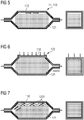
- Figure 5 shows the problem of packing of the heat storage material. An additional path on the ceiling of the heat exchange chamber for flow of heat transfer fluid is available. The control of heat exchange flow through the heat exchange chamber interior is crucial. Based on the invention the gap is reduced.
- the ceiling of the heat exchange chamber is just laid on the heat storage material. Due to gravity force (or vacuum in the heat exchange chamber interior by sucking of gaseous heat transfer fluid), the ceiling is pressed to the heat storage material ( figure 6 ). With the installation of guidance system (e.g. rail guidance) or rim structures (e.g. notches, indentations, grooves) along the borders of the ceiling and supporting structure an even lowering (vertical movement) of the ceiling is ensured. The lowering of the ceiling and the sealing of the gap occurs due to the ceilings net weight. Furthermore the guidance of the ceiling and the connections to the walls are designed such that no leakage occurs in the heat storage unit. Additionally it is possible to cover the entire storage with a foil to ensure leakage tightness. This foil is glued to the outer storage containment and can be made of EPDM foil.
- flow flaps are used to compensate the packing of the heat storage material.
- passive flow flaps are installed over the whole heat exchange chamber storage length. These flow flaps are mounted with a flexible bearing, as shown in figure 7 .
- the flow flaps close the gap between the ceiling and the actual filling height continuously due to their net weight. It is also possible to build the ceiling, also as firmly connected support structure, to close the gap passive flow flaps are installed over the whole storage length. These flow flaps are mounted with a flexible bearing, as shown in figure 7 .
- the flow flaps close the gap between the ceiling of the heat exchange chamber and the actually filling height continuously due to their net weight.
- the embodiment concerning figure 8 the flexible flow obstacle 1232) comprises an air bag.
- one or more air bags can be installed between the supporting structure of the heat storage and the lowering, insulated ceiling.
- the number and the size of installed air bags depend on the permeability of the insulation above the storage material towards the heat transfer fluid.
- the air bags block the heat transfer fluid, so that it has to flow through the storage material to reach the second opening.
- the air bag has to be made out of a flexible, elastic material which adapts to the form of the gap. It also needs to be temperature resistant to the temperatures occurring above the insulated ceiling.
- the volume of the air bag has to adapt to the volume of the gap (especially height and width if the length of the air bag is parallel to the flow direction of the heat transfer fluid) at all times during operation.
- This can be solved by pumping a fluid (e.g. air) into the air bag when the storage is cooled down (discharging) and by pumping a fluid out of the air bag when the storage is heated up (charging) in a way that the pressure in the air bag is kept at a constant level.
- a fluid e.g. air
- Another option to increase the flow resistance between the insulated ceiling (118) and the supporting structure of the heat storage material is to install flexible flow obstacles which cover the entire cross section of the growing gap (see figure 10 .
- These flow obstacles are connected to both the supporting structure above and the insulated ceiling underneath which lies on top of the storage material.
- the flow obstacles do not absorb any forces resulting from the lowering of the insulated ceiling so that the insulated ceiling is always in direct contact with the storage material due to gravity and/or the low pressure inside the void volume of the storage material.
- the flow obstacles can be made out of temperature resistant fabrics with a high flow resistance and they can be folded before the first operation of the heat storage starts as indicated in Figure 5 .
- the folded fabrics will step by step unfold and therefore they will cover the cross section of the gap entirely at all times.
- a further embodiment results by at least partly digging of the heat exchange chamber: In order to reduce the installation cost of the heat exchange chamber and in order to create a volume adapting containment (heat exchange chamber with the packing device) the heat exchange chamber is at least partly located in an excavation.
- the heat storage material comprises stone. Loads of the heat exchange chamber, e.g. due to thermal expansion and gravity forces, will be supported by the surrounding soil and a flexible ceiling.
- the boundaries of the heat exchange chamber and the base of the heat exchange chamber can be made out of concrete, steel, porous concrete, foamed clay or any other building material which is able to separate the surrounding soil from the storage material inside.
- sheet pile walls can be a cheap and simple way to build an airtight boundary between storage material and soil.
- Locks of the sheet pile wall are be welded so that the sheet pile wall is airtight.
- the sheet pile wall and the base of the heat exchange chamber form a fixed and defined shape so that the heat transfer fluid can be distributed and flow optimally through the heat exchange chamber interior with the stones.
- the heat exchange chamber with the heat storage material is more independent from a quality of the surrounding soil. Therefore, the number of possible locations to install the heat exchange chamber of the heat exchange system increases.
- a fixed shape of the heat exchange chamber prevents the excavation from flattening due to thermal expansion and shrinking which would increase heat losses due to declined insulation and increased surface.
- Thermal insulation layers are attached to the heat exchange boundaries (e.g. ceiling, side walls or vase) either on the inside or on the outside to reduce heat losses and to save the surrounding soil from overheating.
- the insulation material is selected from the group of ceramics, sinter, bricks, foamed clay, mineral wool, mineral foam, mineral fibers, foam glass, vermiculite, perlite, chamotte, formed vacuum components, calcium silicate, and microporous insulation material.
- a flexible layer of thermal insulation covers the heat storage material.
- an inner layer to protect the entire thermal insulation layer from abrasion is to be installed.
- an airtight foil is installed.
- This foil can be installed in between the supporting structure (heat exchange chamber boundaries like heat exchange chamber wall or base of the heat exchange chamber) and the insulation layer.
- the airtight foil on top of the heat exchange chamber directly lies on top of the insulation layer.
- the foil can be tightly connected to the top of the side walls of the heat exchange chamber so that no air gaps will occur. To avoid tearing of the airtight foil, it can be installed with wrinkles so that it can unfold in the case of a thermal expansion of the heat storage material.
- the thermal insulation layer (or the abrasion protection layer) directly lies on top of the heat storage material so that no further supportive structure is needed here.
- a soil layer is located on top of the thermal insulation layer to cover it.
- the soil on top of the heat exchange chamber is preferably the soil taken from the excavation in order to avoid expensive transportation.
- the thermal insulation layer which lies on top of the heat storage material can be straight or curved depending on its total expansion and/or shrinking due to the temperature changes and the load resulting from the soil on top of it to avoid a formation of air gaps
- the first opening (inlet opening) and the second opening (outlet opening) of the heat exchange chamber are tightly connected to the supporting structure so that no heat transfer fluid can leak.
- the defined shape of the heat exchange chamber boundaries of the heat exchange chamber prevent the first and the second opening from shifting. This results in an optimal position of the first and second opening throughout the entire lifecycle of the heat exchange chamber so that the heat transfer fluid is distributed ideally.
Landscapes
- Engineering & Computer Science (AREA)
- Physics & Mathematics (AREA)
- Thermal Sciences (AREA)
- Mechanical Engineering (AREA)
- General Engineering & Computer Science (AREA)
- Heat-Exchange Devices With Radiators And Conduit Assemblies (AREA)
Claims (11)
- Système d'échange de chaleur (1), avec- au moins une chambre d'échange de chaleur (11) avec des limites de chambre d'échange de chaleur (111) qui entourent au moins un intérieur de chambre d'échange de chaleur (112) de la chambre d'échange de chaleur (11), dans lequel- les limites de chambre d'échange de chaleur (111) comprennent au moins une première ouverture (1111) destinée à guider un flux entrant (132) d'au moins un fluide de transfert de chaleur (131) dans l'intérieur de chambre d'échange de chaleur (112) et au moins une deuxième ouverture (1112) destinée à guider un flux sortant (133) du fluide de transfert de chaleur (131) hors de l'intérieur de chambre d'échange de chaleur (112) ;- au moins un matériau d'emmagasinage de chaleur (121) est agencé dans l'intérieur de chambre d'échange de chaleur (112) de telle sorte qu'un flux d'échange de chaleur (13) du fluide de transfert de chaleur (131) à travers l'intérieur de chambre d'échange de chaleur (112) génère un échange de chaleur entre le matériau d'emmagasinage de chaleur (121) et le fluide de transfert de chaleur (131) ; caractérisé en ce que- la chambre d'échange de chaleur (11) comprend au moins un dispositif de garnissage (123) pour une compensation de vide, le vide résultant d'un garnissage du matériau d'emmagasinage de chaleur (131) au sein de l'intérieur de chambre d'échange de chaleur (112),dans lequel le dispositif de garnissage (123) est un plafond à coulissement vertical (118) de la chambre d'échange de chaleur (11) qui se trouve par-dessus le matériau d'emmagasinage de chaleur (131)
et/ou
le dispositif de garnissage (123) est une paroi de palplanches souple faisant partie d'au moins l'une d'une limite de chambre d'échange de chaleur latérale (1115) de la chambre d'échange thermique (11). - Système d'échange de chaleur selon la revendication 1, dans lequel le dispositif de garnissage comprend en outre au moins un obstacle à l'écoulement souple (1232) pour le flux d'échange de chaleur (13).
- Système d'échange de chaleur selon la revendication 2, dans lequel l'obstacle à l'écoulement souple (1232) comprend au moins une poche qui est remplie d'air.
- Système d'échange de chaleur selon l'une des revendications 1 à 3, dans lequel le plafond et une limite de chambre d'échange de chaleur latérale (1115) sont reliés ensemble et scellés hermétiquement.
- Système d'échange de chaleur selon l'une des revendications 1 à 4, dans lequel le dispositif de garnissage est agencé entre au moins une limite d'échange de chaleur de la chambre d'échange de chaleur et le matériau d'emmagasinage de chaleur.
- Système d'échange de chaleur selon l'une des revendications 1 à 5, dans lequel le dispositif de garnissage comprend des volets de contrôle de flux.
- Système d'échange de chaleur selon la revendication 6, dans lequel les volets de contrôle de flux sont des volets de contrôle de flux passifs qui sont agencés au niveau du plafond de la chambre d'échange de chaleur.
- Système d'échange de chaleur selon l'une des revendications 1 à 7, dans lequel le fluide de transfert de fluide comprend un gaz à la pression de gaz ambiante.
- Système d'échange de chaleur selon l'une des revendications 1 à 8, dans lequel la chambre d'échange de chaleur (11) est agencée au moins en partie dans au moins une excavation de sol (160) d'un sol (161).
- Système d'échange de chaleur selon la revendication 9, dans lequel au moins l'une des limites de chambre d'échange de chaleur (111) est formée au moins en partie par au moins une limite de sol (1601).
- Procédé destiné à échanger de la chaleur en utilisant le système d'échange de chaleur selon l'une des revendications 1 à 10, dans lequel dans un mode de fonctionnement du système d'échange de chaleur le flux d'échange de chaleur du fluide de transfert de chaleur est guidé à travers l'intérieur de chambre d'échange de chaleur, dans lequel un échange de chaleur entre le matériau d'emmagasinage de chaleur et le fluide de transfert de chaleur est généré.
Applications Claiming Priority (2)
| Application Number | Priority Date | Filing Date | Title |
|---|---|---|---|
| EP15187768 | 2015-09-30 | ||
| PCT/EP2016/073294 WO2017055472A1 (fr) | 2015-09-30 | 2016-09-29 | Système d'échange de chaleur présentant une compensation de changement de dimension de matériau de stockage de chaleur, et procédé d'échange de chaleur utilisant le système d'échange de chaleur |
Publications (2)
| Publication Number | Publication Date |
|---|---|
| EP3308092A1 EP3308092A1 (fr) | 2018-04-18 |
| EP3308092B1 true EP3308092B1 (fr) | 2019-06-19 |
Family
ID=54256566
Family Applications (1)
| Application Number | Title | Priority Date | Filing Date |
|---|---|---|---|
| EP16775676.6A Not-in-force EP3308092B1 (fr) | 2015-09-30 | 2016-09-29 | Système d'échange de chaleur présentant une compensation de changement de dimension de matériau de stockage de chaleur, et procédé d'échange de chaleur utilisant le système d'échange de chaleur |
Country Status (5)
| Country | Link |
|---|---|
| US (1) | US10982909B2 (fr) |
| EP (1) | EP3308092B1 (fr) |
| CN (1) | CN108139169B (fr) |
| ES (1) | ES2749703T3 (fr) |
| WO (1) | WO2017055472A1 (fr) |
Families Citing this family (7)
| Publication number | Priority date | Publication date | Assignee | Title |
|---|---|---|---|---|
| DE102014212676B4 (de) * | 2014-07-01 | 2019-03-14 | Horst Schierack | Energiespeichereinrichtung zur Zwischenspeicherung von thermischer Energie, Kraftwerk mit einer Energiespeichereinrichtung sowie Verfahren zum Betreiben einer Energiespeichereinrichtung |
| WO2017055472A1 (fr) | 2015-09-30 | 2017-04-06 | Siemens Aktiengesellschaft | Système d'échange de chaleur présentant une compensation de changement de dimension de matériau de stockage de chaleur, et procédé d'échange de chaleur utilisant le système d'échange de chaleur |
| EP3764048A1 (fr) * | 2019-07-09 | 2021-01-13 | Siemens Gamesa Renewable Energy GmbH & Co. KG | Stockage d'énergie thermique |
| EP3865805A1 (fr) * | 2020-02-12 | 2021-08-18 | Siemens Gamesa Renewable Energy GmbH & Co. KG | Accumulateur de chaleur et procédé et appareil de formation d'un accumulateur de chaleur |
| EP3865806A1 (fr) * | 2020-02-12 | 2021-08-18 | Siemens Gamesa Renewable Energy GmbH & Co. KG | Dispositif de stockage d'énergie thermique |
| EP3865804A1 (fr) | 2020-02-12 | 2021-08-18 | Siemens Gamesa Renewable Energy GmbH & Co. KG | Dispositif de stockage d'énergie thermique |
| EP4174430A1 (fr) | 2021-11-02 | 2023-05-03 | Siemens Gamesa Renewable Energy GmbH & Co. KG | Dispositif de stockage d'énergie thermique avec protection contre la surpression |
Family Cites Families (12)
| Publication number | Priority date | Publication date | Assignee | Title |
|---|---|---|---|---|
| US6892797B2 (en) * | 2001-12-21 | 2005-05-17 | Honeywell International, Inc. | Heat exchanger with biased and expandable core support structure |
| US20080066736A1 (en) * | 2006-07-25 | 2008-03-20 | Yanong Zhu | Method and apparatus for solar energy storage system using gas and rock |
| US20090090109A1 (en) * | 2007-06-06 | 2009-04-09 | Mills David R | Granular thermal energy storage mediums and devices for thermal energy storage systems |
| JP5118500B2 (ja) * | 2008-02-04 | 2013-01-16 | 本田技研工業株式会社 | 蓄熱容器 |
| WO2011104556A2 (fr) * | 2010-02-24 | 2011-09-01 | Isentropic Limited | Système amélioré pour le stockage de chaleur |
| CH703780A2 (de) * | 2010-08-30 | 2012-03-15 | Airlight Energy Ip Sa | Wärmespeicher. |
| EP2492119A3 (fr) * | 2011-02-22 | 2013-10-09 | Handtmann Systemtechnik GmbH & Co. KG | Accumulateur thermique latent |
| US8567388B2 (en) * | 2011-02-23 | 2013-10-29 | Apricus Inc | Hotwater tank |
| WO2013101370A1 (fr) * | 2011-11-22 | 2013-07-04 | Gerpheide George E | Système d'exploitation minière présentant un réservoir d'énergie durable existant |
| CN103423798A (zh) * | 2012-05-23 | 2013-12-04 | 新疆太阳能科技开发公司 | 太阳能地埋跨季储热供暖系统专用地埋蓄热库 |
| WO2017055472A1 (fr) | 2015-09-30 | 2017-04-06 | Siemens Aktiengesellschaft | Système d'échange de chaleur présentant une compensation de changement de dimension de matériau de stockage de chaleur, et procédé d'échange de chaleur utilisant le système d'échange de chaleur |
| EP3314186B1 (fr) | 2015-09-30 | 2022-03-09 | Siemens Gamesa Renewable Energy A/S | Système d'échange de chaleur à chambre d'échange de chaleur avec une feuille, procédé de fabrication du système d'échange de chaleur et procédé d'échange de chaleur en utilisant le système d'échange de chaleur |
-
2016
- 2016-09-29 WO PCT/EP2016/073294 patent/WO2017055472A1/fr not_active Ceased
- 2016-09-29 CN CN201680057663.4A patent/CN108139169B/zh not_active Expired - Fee Related
- 2016-09-29 US US15/752,600 patent/US10982909B2/en not_active Expired - Fee Related
- 2016-09-29 ES ES16775676T patent/ES2749703T3/es active Active
- 2016-09-29 EP EP16775676.6A patent/EP3308092B1/fr not_active Not-in-force
Non-Patent Citations (1)
| Title |
|---|
| None * |
Also Published As
| Publication number | Publication date |
|---|---|
| WO2017055472A1 (fr) | 2017-04-06 |
| EP3308092A1 (fr) | 2018-04-18 |
| CN108139169A (zh) | 2018-06-08 |
| US10982909B2 (en) | 2021-04-20 |
| US20180245860A1 (en) | 2018-08-30 |
| CN108139169B (zh) | 2020-06-26 |
| ES2749703T3 (es) | 2020-03-23 |
Similar Documents
| Publication | Publication Date | Title |
|---|---|---|
| EP3308092B1 (fr) | Système d'échange de chaleur présentant une compensation de changement de dimension de matériau de stockage de chaleur, et procédé d'échange de chaleur utilisant le système d'échange de chaleur | |
| EP3308091B1 (fr) | Système d'échange de chaleur à chambre d'échange de chaleur à couche d'isolation thermique, procédé de fabrication d'un système d'échange de chaleur et procédé d'échange de chaleur en utilisant le système d'échange de chaleur | |
| EP3102796B1 (fr) | Système d'échange d'énergie thermique à haute température et procédé d'échange d'énergie thermique à l'aide dudit système d'échange d'énergie thermique à haute température | |
| US10563927B2 (en) | High temperature thermal energy exchange system with horizontal heat exchange chamber and method for exchanging thermal energy by using the high temperature thermal energy exchange system | |
| US10724805B2 (en) | Charging system with a high temperature thermal energy exchange system and method for charging heat storage material of the high temperature thermal energy exchange system with thermal energy | |
| EP3172413B2 (fr) | Centrale électrique à cycle vapeur et système d'échange d'énergie thermique à haute température et procédé de fabrication de centrale électrique | |
| WO2016050367A1 (fr) | Système d'évacuation à système d'échange d'énergie thermique à haute température et procédé | |
| EP3303967B1 (fr) | Système d'échange de chaleur avec au moins deux chambres d'échange de chaleur, et procédé d'échange de chaleur utilisant le système d'échange de chaleur | |
| EP3314186B1 (fr) | Système d'échange de chaleur à chambre d'échange de chaleur avec une feuille, procédé de fabrication du système d'échange de chaleur et procédé d'échange de chaleur en utilisant le système d'échange de chaleur | |
| EP3308089B1 (fr) | Système d'échange de chaleur avec chambre d'échange de chaleur principale et chambre d'échange de chaleur auxiliaire, et procédé d'échange de chaleur utilisant le système d'échange de chaleur | |
| EP3308090B1 (fr) | Système d'échange de chaleur doté d'un dispositif de mouvement de fluide actif de joint pour le mode de charge et pour le mode de décharge et procédé d'échange de chaleur en utilisant le système d'échange de chaleur | |
| WO2017055475A1 (fr) | Système d'échange de chaleur à chambre d'échange de chaleur dans une excavation de sol, procédé de fabrication de système d'échange de chaleur et procédé d'échange de chaleur en utilisant le système d'échange de chaleur | |
| EP3322955B1 (fr) | Système d'échange de chaleur avec consommation d'énergie constante et procédé d'échange de chaleur utilisant le système d'échange de chaleur |
Legal Events
| Date | Code | Title | Description |
|---|---|---|---|
| STAA | Information on the status of an ep patent application or granted ep patent |
Free format text: STATUS: THE INTERNATIONAL PUBLICATION HAS BEEN MADE |
|
| PUAI | Public reference made under article 153(3) epc to a published international application that has entered the european phase |
Free format text: ORIGINAL CODE: 0009012 |
|
| STAA | Information on the status of an ep patent application or granted ep patent |
Free format text: STATUS: REQUEST FOR EXAMINATION WAS MADE |
|
| 17P | Request for examination filed |
Effective date: 20180112 |
|
| AK | Designated contracting states |
Kind code of ref document: A1 Designated state(s): AL AT BE BG CH CY CZ DE DK EE ES FI FR GB GR HR HU IE IS IT LI LT LU LV MC MK MT NL NO PL PT RO RS SE SI SK SM TR |
|
| AX | Request for extension of the european patent |
Extension state: BA ME |
|
| DAV | Request for validation of the european patent (deleted) | ||
| DAX | Request for extension of the european patent (deleted) | ||
| GRAP | Despatch of communication of intention to grant a patent |
Free format text: ORIGINAL CODE: EPIDOSNIGR1 |
|
| STAA | Information on the status of an ep patent application or granted ep patent |
Free format text: STATUS: GRANT OF PATENT IS INTENDED |
|
| INTG | Intention to grant announced |
Effective date: 20190129 |
|
| GRAS | Grant fee paid |
Free format text: ORIGINAL CODE: EPIDOSNIGR3 |
|
| RAP1 | Party data changed (applicant data changed or rights of an application transferred) |
Owner name: SIEMENS GAMESA RENEWABLE ENERGY A/S |
|
| GRAA | (expected) grant |
Free format text: ORIGINAL CODE: 0009210 |
|
| STAA | Information on the status of an ep patent application or granted ep patent |
Free format text: STATUS: THE PATENT HAS BEEN GRANTED |
|
| AK | Designated contracting states |
Kind code of ref document: B1 Designated state(s): AL AT BE BG CH CY CZ DE DK EE ES FI FR GB GR HR HU IE IS IT LI LT LU LV MC MK MT NL NO PL PT RO RS SE SI SK SM TR |
|
| REG | Reference to a national code |
Ref country code: GB Ref legal event code: FG4D |
|
| REG | Reference to a national code |
Ref country code: CH Ref legal event code: EP |
|
| REG | Reference to a national code |
Ref country code: IE Ref legal event code: FG4D |
|
| REG | Reference to a national code |
Ref country code: DE Ref legal event code: R096 Ref document number: 602016015690 Country of ref document: DE |
|
| REG | Reference to a national code |
Ref country code: AT Ref legal event code: REF Ref document number: 1146060 Country of ref document: AT Kind code of ref document: T Effective date: 20190715 |
|
| REG | Reference to a national code |
Ref country code: NL Ref legal event code: MP Effective date: 20190619 |
|
| PG25 | Lapsed in a contracting state [announced via postgrant information from national office to epo] |
Ref country code: FI Free format text: LAPSE BECAUSE OF FAILURE TO SUBMIT A TRANSLATION OF THE DESCRIPTION OR TO PAY THE FEE WITHIN THE PRESCRIBED TIME-LIMIT Effective date: 20190619 Ref country code: NO Free format text: LAPSE BECAUSE OF FAILURE TO SUBMIT A TRANSLATION OF THE DESCRIPTION OR TO PAY THE FEE WITHIN THE PRESCRIBED TIME-LIMIT Effective date: 20190919 Ref country code: LT Free format text: LAPSE BECAUSE OF FAILURE TO SUBMIT A TRANSLATION OF THE DESCRIPTION OR TO PAY THE FEE WITHIN THE PRESCRIBED TIME-LIMIT Effective date: 20190619 Ref country code: HR Free format text: LAPSE BECAUSE OF FAILURE TO SUBMIT A TRANSLATION OF THE DESCRIPTION OR TO PAY THE FEE WITHIN THE PRESCRIBED TIME-LIMIT Effective date: 20190619 Ref country code: SE Free format text: LAPSE BECAUSE OF FAILURE TO SUBMIT A TRANSLATION OF THE DESCRIPTION OR TO PAY THE FEE WITHIN THE PRESCRIBED TIME-LIMIT Effective date: 20190619 Ref country code: AL Free format text: LAPSE BECAUSE OF FAILURE TO SUBMIT A TRANSLATION OF THE DESCRIPTION OR TO PAY THE FEE WITHIN THE PRESCRIBED TIME-LIMIT Effective date: 20190619 |
|
| REG | Reference to a national code |
Ref country code: LT Ref legal event code: MG4D |
|
| PG25 | Lapsed in a contracting state [announced via postgrant information from national office to epo] |
Ref country code: GR Free format text: LAPSE BECAUSE OF FAILURE TO SUBMIT A TRANSLATION OF THE DESCRIPTION OR TO PAY THE FEE WITHIN THE PRESCRIBED TIME-LIMIT Effective date: 20190920 Ref country code: BG Free format text: LAPSE BECAUSE OF FAILURE TO SUBMIT A TRANSLATION OF THE DESCRIPTION OR TO PAY THE FEE WITHIN THE PRESCRIBED TIME-LIMIT Effective date: 20190919 Ref country code: LV Free format text: LAPSE BECAUSE OF FAILURE TO SUBMIT A TRANSLATION OF THE DESCRIPTION OR TO PAY THE FEE WITHIN THE PRESCRIBED TIME-LIMIT Effective date: 20190619 Ref country code: RS Free format text: LAPSE BECAUSE OF FAILURE TO SUBMIT A TRANSLATION OF THE DESCRIPTION OR TO PAY THE FEE WITHIN THE PRESCRIBED TIME-LIMIT Effective date: 20190619 |
|
| REG | Reference to a national code |
Ref country code: AT Ref legal event code: MK05 Ref document number: 1146060 Country of ref document: AT Kind code of ref document: T Effective date: 20190619 |
|
| PG25 | Lapsed in a contracting state [announced via postgrant information from national office to epo] |
Ref country code: SK Free format text: LAPSE BECAUSE OF FAILURE TO SUBMIT A TRANSLATION OF THE DESCRIPTION OR TO PAY THE FEE WITHIN THE PRESCRIBED TIME-LIMIT Effective date: 20190619 Ref country code: RO Free format text: LAPSE BECAUSE OF FAILURE TO SUBMIT A TRANSLATION OF THE DESCRIPTION OR TO PAY THE FEE WITHIN THE PRESCRIBED TIME-LIMIT Effective date: 20190619 Ref country code: CZ Free format text: LAPSE BECAUSE OF FAILURE TO SUBMIT A TRANSLATION OF THE DESCRIPTION OR TO PAY THE FEE WITHIN THE PRESCRIBED TIME-LIMIT Effective date: 20190619 Ref country code: NL Free format text: LAPSE BECAUSE OF FAILURE TO SUBMIT A TRANSLATION OF THE DESCRIPTION OR TO PAY THE FEE WITHIN THE PRESCRIBED TIME-LIMIT Effective date: 20190619 Ref country code: PT Free format text: LAPSE BECAUSE OF FAILURE TO SUBMIT A TRANSLATION OF THE DESCRIPTION OR TO PAY THE FEE WITHIN THE PRESCRIBED TIME-LIMIT Effective date: 20191021 Ref country code: EE Free format text: LAPSE BECAUSE OF FAILURE TO SUBMIT A TRANSLATION OF THE DESCRIPTION OR TO PAY THE FEE WITHIN THE PRESCRIBED TIME-LIMIT Effective date: 20190619 Ref country code: AT Free format text: LAPSE BECAUSE OF FAILURE TO SUBMIT A TRANSLATION OF THE DESCRIPTION OR TO PAY THE FEE WITHIN THE PRESCRIBED TIME-LIMIT Effective date: 20190619 |
|
| PG25 | Lapsed in a contracting state [announced via postgrant information from national office to epo] |
Ref country code: IT Free format text: LAPSE BECAUSE OF FAILURE TO SUBMIT A TRANSLATION OF THE DESCRIPTION OR TO PAY THE FEE WITHIN THE PRESCRIBED TIME-LIMIT Effective date: 20190619 Ref country code: SM Free format text: LAPSE BECAUSE OF FAILURE TO SUBMIT A TRANSLATION OF THE DESCRIPTION OR TO PAY THE FEE WITHIN THE PRESCRIBED TIME-LIMIT Effective date: 20190619 Ref country code: IS Free format text: LAPSE BECAUSE OF FAILURE TO SUBMIT A TRANSLATION OF THE DESCRIPTION OR TO PAY THE FEE WITHIN THE PRESCRIBED TIME-LIMIT Effective date: 20191019 |
|
| REG | Reference to a national code |
Ref country code: ES Ref legal event code: FG2A Ref document number: 2749703 Country of ref document: ES Kind code of ref document: T3 Effective date: 20200323 |
|
| PG25 | Lapsed in a contracting state [announced via postgrant information from national office to epo] |
Ref country code: TR Free format text: LAPSE BECAUSE OF FAILURE TO SUBMIT A TRANSLATION OF THE DESCRIPTION OR TO PAY THE FEE WITHIN THE PRESCRIBED TIME-LIMIT Effective date: 20190619 |
|
| PG25 | Lapsed in a contracting state [announced via postgrant information from national office to epo] |
Ref country code: PL Free format text: LAPSE BECAUSE OF FAILURE TO SUBMIT A TRANSLATION OF THE DESCRIPTION OR TO PAY THE FEE WITHIN THE PRESCRIBED TIME-LIMIT Effective date: 20190619 Ref country code: DK Free format text: LAPSE BECAUSE OF FAILURE TO SUBMIT A TRANSLATION OF THE DESCRIPTION OR TO PAY THE FEE WITHIN THE PRESCRIBED TIME-LIMIT Effective date: 20190619 |
|
| PG25 | Lapsed in a contracting state [announced via postgrant information from national office to epo] |
Ref country code: MC Free format text: LAPSE BECAUSE OF FAILURE TO SUBMIT A TRANSLATION OF THE DESCRIPTION OR TO PAY THE FEE WITHIN THE PRESCRIBED TIME-LIMIT Effective date: 20190619 Ref country code: IS Free format text: LAPSE BECAUSE OF FAILURE TO SUBMIT A TRANSLATION OF THE DESCRIPTION OR TO PAY THE FEE WITHIN THE PRESCRIBED TIME-LIMIT Effective date: 20200224 |
|
| REG | Reference to a national code |
Ref country code: CH Ref legal event code: PL |
|
| REG | Reference to a national code |
Ref country code: DE Ref legal event code: R097 Ref document number: 602016015690 Country of ref document: DE |
|
| PLBE | No opposition filed within time limit |
Free format text: ORIGINAL CODE: 0009261 |
|
| STAA | Information on the status of an ep patent application or granted ep patent |
Free format text: STATUS: NO OPPOSITION FILED WITHIN TIME LIMIT |
|
| PG2D | Information on lapse in contracting state deleted |
Ref country code: IS |
|
| PG25 | Lapsed in a contracting state [announced via postgrant information from national office to epo] |
Ref country code: LU Free format text: LAPSE BECAUSE OF NON-PAYMENT OF DUE FEES Effective date: 20190929 Ref country code: IE Free format text: LAPSE BECAUSE OF NON-PAYMENT OF DUE FEES Effective date: 20190929 Ref country code: CH Free format text: LAPSE BECAUSE OF NON-PAYMENT OF DUE FEES Effective date: 20190930 Ref country code: LI Free format text: LAPSE BECAUSE OF NON-PAYMENT OF DUE FEES Effective date: 20190930 |
|
| REG | Reference to a national code |
Ref country code: BE Ref legal event code: MM Effective date: 20190930 |
|
| 26N | No opposition filed |
Effective date: 20200603 |
|
| PG25 | Lapsed in a contracting state [announced via postgrant information from national office to epo] |
Ref country code: SI Free format text: LAPSE BECAUSE OF FAILURE TO SUBMIT A TRANSLATION OF THE DESCRIPTION OR TO PAY THE FEE WITHIN THE PRESCRIBED TIME-LIMIT Effective date: 20190619 Ref country code: BE Free format text: LAPSE BECAUSE OF NON-PAYMENT OF DUE FEES Effective date: 20190930 |
|
| PG25 | Lapsed in a contracting state [announced via postgrant information from national office to epo] |
Ref country code: FR Free format text: LAPSE BECAUSE OF NON-PAYMENT OF DUE FEES Effective date: 20190930 |
|
| PG25 | Lapsed in a contracting state [announced via postgrant information from national office to epo] |
Ref country code: CY Free format text: LAPSE BECAUSE OF FAILURE TO SUBMIT A TRANSLATION OF THE DESCRIPTION OR TO PAY THE FEE WITHIN THE PRESCRIBED TIME-LIMIT Effective date: 20190619 |
|
| PG25 | Lapsed in a contracting state [announced via postgrant information from national office to epo] |
Ref country code: MT Free format text: LAPSE BECAUSE OF FAILURE TO SUBMIT A TRANSLATION OF THE DESCRIPTION OR TO PAY THE FEE WITHIN THE PRESCRIBED TIME-LIMIT Effective date: 20190619 Ref country code: HU Free format text: LAPSE BECAUSE OF FAILURE TO SUBMIT A TRANSLATION OF THE DESCRIPTION OR TO PAY THE FEE WITHIN THE PRESCRIBED TIME-LIMIT; INVALID AB INITIO Effective date: 20160929 |
|
| PG25 | Lapsed in a contracting state [announced via postgrant information from national office to epo] |
Ref country code: MK Free format text: LAPSE BECAUSE OF FAILURE TO SUBMIT A TRANSLATION OF THE DESCRIPTION OR TO PAY THE FEE WITHIN THE PRESCRIBED TIME-LIMIT Effective date: 20190619 |
|
| REG | Reference to a national code |
Ref country code: DE Ref legal event code: R082 Ref document number: 602016015690 Country of ref document: DE Representative=s name: SAUTHOFF, KARSTEN, DIPL.-ING. UNIV., DE |
|
| PGFP | Annual fee paid to national office [announced via postgrant information from national office to epo] |
Ref country code: GB Payment date: 20220927 Year of fee payment: 7 Ref country code: DE Payment date: 20220920 Year of fee payment: 7 |
|
| PGFP | Annual fee paid to national office [announced via postgrant information from national office to epo] |
Ref country code: ES Payment date: 20221018 Year of fee payment: 7 |
|
| REG | Reference to a national code |
Ref country code: DE Ref legal event code: R119 Ref document number: 602016015690 Country of ref document: DE |
|
| GBPC | Gb: european patent ceased through non-payment of renewal fee |
Effective date: 20230929 |
|
| PG25 | Lapsed in a contracting state [announced via postgrant information from national office to epo] |
Ref country code: GB Free format text: LAPSE BECAUSE OF NON-PAYMENT OF DUE FEES Effective date: 20230929 |
|
| PG25 | Lapsed in a contracting state [announced via postgrant information from national office to epo] |
Ref country code: GB Free format text: LAPSE BECAUSE OF NON-PAYMENT OF DUE FEES Effective date: 20230929 Ref country code: DE Free format text: LAPSE BECAUSE OF NON-PAYMENT OF DUE FEES Effective date: 20240403 |
|
| REG | Reference to a national code |
Ref country code: ES Ref legal event code: FD2A Effective date: 20241106 |
|
| PG25 | Lapsed in a contracting state [announced via postgrant information from national office to epo] |
Ref country code: ES Free format text: LAPSE BECAUSE OF NON-PAYMENT OF DUE FEES Effective date: 20230930 |
|
| PG25 | Lapsed in a contracting state [announced via postgrant information from national office to epo] |
Ref country code: ES Free format text: LAPSE BECAUSE OF NON-PAYMENT OF DUE FEES Effective date: 20230930 |