EP3308231B1 - Appareil doté d'un refroidissement surveillé - Google Patents
Appareil doté d'un refroidissement surveillé Download PDFInfo
- Publication number
- EP3308231B1 EP3308231B1 EP16730786.7A EP16730786A EP3308231B1 EP 3308231 B1 EP3308231 B1 EP 3308231B1 EP 16730786 A EP16730786 A EP 16730786A EP 3308231 B1 EP3308231 B1 EP 3308231B1
- Authority
- EP
- European Patent Office
- Prior art keywords
- operating state
- cooling
- components
- monitoring unit
- welding
- Prior art date
- Legal status (The legal status is an assumption and is not a legal conclusion. Google has not performed a legal analysis and makes no representation as to the accuracy of the status listed.)
- Active
Links
Images



Classifications
-
- B—PERFORMING OPERATIONS; TRANSPORTING
- B23—MACHINE TOOLS; METAL-WORKING NOT OTHERWISE PROVIDED FOR
- B23K—SOLDERING OR UNSOLDERING; WELDING; CLADDING OR PLATING BY SOLDERING OR WELDING; CUTTING BY APPLYING HEAT LOCALLY, e.g. FLAME CUTTING; WORKING BY LASER BEAM
- B23K9/00—Arc welding or cutting
- B23K9/32—Accessories
- B23K9/321—Protecting means
-
- B—PERFORMING OPERATIONS; TRANSPORTING
- B23—MACHINE TOOLS; METAL-WORKING NOT OTHERWISE PROVIDED FOR
- B23K—SOLDERING OR UNSOLDERING; WELDING; CLADDING OR PLATING BY SOLDERING OR WELDING; CUTTING BY APPLYING HEAT LOCALLY, e.g. FLAME CUTTING; WORKING BY LASER BEAM
- B23K11/00—Resistance welding; Severing by resistance heating
- B23K11/24—Electric supply or control circuits therefor
- B23K11/241—Electric supplies
-
- B—PERFORMING OPERATIONS; TRANSPORTING
- B23—MACHINE TOOLS; METAL-WORKING NOT OTHERWISE PROVIDED FOR
- B23K—SOLDERING OR UNSOLDERING; WELDING; CLADDING OR PLATING BY SOLDERING OR WELDING; CUTTING BY APPLYING HEAT LOCALLY, e.g. FLAME CUTTING; WORKING BY LASER BEAM
- B23K37/00—Auxiliary devices or processes, not specially adapted for a procedure covered by only one of the other main groups of this subclass
- B23K37/003—Cooling means for welding or cutting
-
- B—PERFORMING OPERATIONS; TRANSPORTING
- B23—MACHINE TOOLS; METAL-WORKING NOT OTHERWISE PROVIDED FOR
- B23K—SOLDERING OR UNSOLDERING; WELDING; CLADDING OR PLATING BY SOLDERING OR WELDING; CUTTING BY APPLYING HEAT LOCALLY, e.g. FLAME CUTTING; WORKING BY LASER BEAM
- B23K37/00—Auxiliary devices or processes, not specially adapted for a procedure covered by only one of the other main groups of this subclass
- B23K37/006—Safety devices for welding or cutting
-
- B—PERFORMING OPERATIONS; TRANSPORTING
- B23—MACHINE TOOLS; METAL-WORKING NOT OTHERWISE PROVIDED FOR
- B23K—SOLDERING OR UNSOLDERING; WELDING; CLADDING OR PLATING BY SOLDERING OR WELDING; CUTTING BY APPLYING HEAT LOCALLY, e.g. FLAME CUTTING; WORKING BY LASER BEAM
- B23K9/00—Arc welding or cutting
- B23K9/095—Monitoring or automatic control of welding parameters
- B23K9/0953—Monitoring or automatic control of welding parameters using computing means
-
- B—PERFORMING OPERATIONS; TRANSPORTING
- B23—MACHINE TOOLS; METAL-WORKING NOT OTHERWISE PROVIDED FOR
- B23K—SOLDERING OR UNSOLDERING; WELDING; CLADDING OR PLATING BY SOLDERING OR WELDING; CUTTING BY APPLYING HEAT LOCALLY, e.g. FLAME CUTTING; WORKING BY LASER BEAM
- B23K9/00—Arc welding or cutting
- B23K9/10—Other electric circuits therefor; Protective circuits; Remote controls
- B23K9/1006—Power supply
-
- B—PERFORMING OPERATIONS; TRANSPORTING
- B23—MACHINE TOOLS; METAL-WORKING NOT OTHERWISE PROVIDED FOR
- B23K—SOLDERING OR UNSOLDERING; WELDING; CLADDING OR PLATING BY SOLDERING OR WELDING; CUTTING BY APPLYING HEAT LOCALLY, e.g. FLAME CUTTING; WORKING BY LASER BEAM
- B23K9/00—Arc welding or cutting
- B23K9/10—Other electric circuits therefor; Protective circuits; Remote controls
- B23K9/1006—Power supply
- B23K9/1043—Power supply characterised by the electric circuit
- B23K9/1056—Power supply characterised by the electric circuit by using digital means
- B23K9/1062—Power supply characterised by the electric circuit by using digital means with computing means
-
- G—PHYSICS
- G05—CONTROLLING; REGULATING
- G05B—CONTROL OR REGULATING SYSTEMS IN GENERAL; FUNCTIONAL ELEMENTS OF SUCH SYSTEMS; MONITORING OR TESTING ARRANGEMENTS FOR SUCH SYSTEMS OR ELEMENTS
- G05B19/00—Program-control systems
- G05B19/02—Program-control systems electric
- G05B19/18—Numerical control [NC], i.e. automatically operating machines, in particular machine tools, e.g. in a manufacturing environment, so as to execute positioning, movement or co-ordinated operations by means of program data in numerical form
- G05B19/406—Numerical control [NC], i.e. automatically operating machines, in particular machine tools, e.g. in a manufacturing environment, so as to execute positioning, movement or co-ordinated operations by means of program data in numerical form characterised by monitoring or safety
-
- G—PHYSICS
- G05—CONTROLLING; REGULATING
- G05B—CONTROL OR REGULATING SYSTEMS IN GENERAL; FUNCTIONAL ELEMENTS OF SUCH SYSTEMS; MONITORING OR TESTING ARRANGEMENTS FOR SUCH SYSTEMS OR ELEMENTS
- G05B23/00—Testing or monitoring of control systems or parts thereof
- G05B23/02—Electric testing or monitoring
- G05B23/0205—Electric testing or monitoring by means of a monitoring system capable of detecting and responding to faults
- G05B23/0218—Electric testing or monitoring by means of a monitoring system capable of detecting and responding to faults characterised by the fault detection method dealing with either existing or incipient faults
- G05B23/0224—Process history based detection method, e.g. whereby history implies the availability of large amounts of data
- G05B23/0227—Qualitative history assessment, whereby the type of data acted upon, e.g. waveforms, images or patterns, is not relevant, e.g. rule based assessment; if-then decisions
- G05B23/0232—Qualitative history assessment, whereby the type of data acted upon, e.g. waveforms, images or patterns, is not relevant, e.g. rule based assessment; if-then decisions based on qualitative trend analysis, e.g. system evolution
-
- G—PHYSICS
- G05—CONTROLLING; REGULATING
- G05B—CONTROL OR REGULATING SYSTEMS IN GENERAL; FUNCTIONAL ELEMENTS OF SUCH SYSTEMS; MONITORING OR TESTING ARRANGEMENTS FOR SUCH SYSTEMS OR ELEMENTS
- G05B23/00—Testing or monitoring of control systems or parts thereof
- G05B23/02—Electric testing or monitoring
- G05B23/0205—Electric testing or monitoring by means of a monitoring system capable of detecting and responding to faults
- G05B23/0218—Electric testing or monitoring by means of a monitoring system capable of detecting and responding to faults characterised by the fault detection method dealing with either existing or incipient faults
- G05B23/0243—Electric testing or monitoring by means of a monitoring system capable of detecting and responding to faults characterised by the fault detection method dealing with either existing or incipient faults model based detection method, e.g. first-principles knowledge model
- G05B23/0245—Electric testing or monitoring by means of a monitoring system capable of detecting and responding to faults characterised by the fault detection method dealing with either existing or incipient faults model based detection method, e.g. first-principles knowledge model based on a qualitative model, e.g. rule based; if-then decisions
-
- G—PHYSICS
- G05—CONTROLLING; REGULATING
- G05B—CONTROL OR REGULATING SYSTEMS IN GENERAL; FUNCTIONAL ELEMENTS OF SUCH SYSTEMS; MONITORING OR TESTING ARRANGEMENTS FOR SUCH SYSTEMS OR ELEMENTS
- G05B23/00—Testing or monitoring of control systems or parts thereof
- G05B23/02—Electric testing or monitoring
- G05B23/0205—Electric testing or monitoring by means of a monitoring system capable of detecting and responding to faults
- G05B23/0259—Electric testing or monitoring by means of a monitoring system capable of detecting and responding to faults characterized by the response to fault detection
- G05B23/0275—Fault isolation and identification, e.g. classify fault; estimate cause or root of failure
-
- H—ELECTRICITY
- H05—ELECTRIC TECHNIQUES NOT OTHERWISE PROVIDED FOR
- H05K—PRINTED CIRCUITS; CASINGS OR CONSTRUCTIONAL DETAILS OF ELECTRIC APPARATUS; MANUFACTURE OF ASSEMBLAGES OF ELECTRICAL COMPONENTS
- H05K7/00—Constructional details common to different types of electric apparatus
- H05K7/20—Modifications to facilitate cooling, ventilating, or heating
- H05K7/20009—Modifications to facilitate cooling, ventilating, or heating using a gaseous coolant in electronic enclosures
- H05K7/20209—Thermal management, e.g. fan control
Definitions
- the invention relates to a device with monitored device cooling and a method for monitoring an operating state of a device cooling in a device, in particular in an energy device that provides or converts an electric current.
- energy devices include battery chargers, inverters, and welders.
- Welding machines have a welding power source, which supplies an electric current to carry out the welding process.
- a welding inverter is an electronic welding power source. Inverter welding equipment is used for various arc welding processes, such as electrode, MIG / MAG, plasma and TIG / TIG welding. Such devices are connected depending on the power one or three phases to a power grid.
- the mains voltage is first rectified and chopped using power semiconductors and transformed by means of a relatively small transformer to a low voltage. Subsequently, the welding current is rectified by means of suitable diodes.
- Energy devices in particular welding power sources, may comprise a multiplicity of different electronic or electromechanical components.
- the power and duty cycle of the welding power source is limited by the permissible component temperatures in the device. If a limit temperature is reached, the device switches off until the component in question has cooled down again.
- Conventional welding machines may have monitoring electronics.
- the DE 196 260 59 A1 describes a welding device with a monitoring electronics, which emits a signal to a switching element when a setpoint is exceeded in order to trigger a switching operation. In this way, in the event of a defect within the welding device, the operating personnel may be at risk of danger to be protected. For example, when a limit temperature is reached, the welding device can be switched off.
- DE 10 2005 058 351 A1 discloses a method of monitoring a welding inverter for resistance welding, wherein a temperature profile is recorded for monitoring the welding inverter, in particular for performing a lifetime estimation.
- US 2009/299531 A1 discloses an electronic device having a deviation value calculation unit that calculates a deviation value from the normal limit of the ratio between a performance index associated with the drive power and the measured rotational speed of the fan, a clogging detection unit; detects, by the deviation value, blockages in an air passage through which the fan sucks air outside the housing and sends to the heater, and a deviation value correction unit that corrects the deviation value according to the aging of the fan's performance, deterioration of the clogging detection capacity caused by the aging compensate the obstruction detection unit.
- the device has a user interface which has a display unit for displaying the operating state deviation of the device cooling, the determined cause of the operating state deviation and instructions for eliminating the determined cause of the operating state deviation of the device cooling.
- the user interface further comprises an input unit for adjusting the current by a user and / or by a central control of a system.
- the components have electronic and / or electromechanical components which have associated cooling units for cooling the respective component.
- the device cooling as a component on at least one ventilation unit which supplies cooling air from the environment of the device further components along a cooling air path within a housing of the device.
- the components along the cooling air path associated with temperature sensors that detect an operating temperature profile at the respective components and report to the monitoring unit of the device.
- this has a current measuring unit, which measures the set current and reports to the monitoring unit.
- the monitoring unit controls at least one actuator, in particular a cooling unit and / or a ventilation unit, as a function of the current operating state of the device cooling.
- the monitoring unit has access to a data memory which stores a data model of the device, in particular a data model of the components contained therein and their spatial position along the cooling air path.
- the monitoring unit reports the operating state of the device cooling via a network interface of the device to a central control of a system.
- the invention further provides a method for monitoring an operating state of a device cooling in a device having the features specified in claim 10.
- an operating state deviation of the device cooling and at least one detected potential cause of the operating state deviation as well as instructions for remedying the corresponding cause via a user interface and / or a network interface of the device are output.
- Fig. 1 shows a schematic block diagram illustrating an embodiment of a device according to the invention 1.
- the device 1 is a possible embodiment of a welding device that supplies a welding torch with an adjustable electrical current.
- the welding apparatus 1 may contain a plurality of different components or components, which are used on the one hand as control electronics and on the other for power electronic purposes. These components or components include, for example, electronic or electromechanical components.
- Fig. 1 schematically shows two components 2-1, 2-2, which are, for example, electronic components or electronic assemblies.
- the two components or assemblies 2-1, 2-2 have an operating temperature T, which is detected in the illustrated embodiment via an associated temperature sensor 3-1, 3-2.
- the temperature sensors each detect an operating temperature profile T (t) of the associated component or the associated module, in particular a power unit, within the welding device 1.
- the temperature sensors 3-1, 3-2 can directly on the associated component 2-1, 2-2 be appropriate or in immediate spatial proximity of the relevant component 2-i are located.
- the components or modules 2-i each have at least one integrated temperature sensor 3-i, which senses the operating temperature curve T (t) of the relevant component 2-i.
- the integrated temperature sensors 3-i are connected via signal lines 4-1, 4-2 to a monitoring unit 5.
- the temperature sensors 3-1, 3-2 transmit the operating temperature curve T (t) of the associated component 2-i to the monitoring unit 5.
- the monitoring unit 5 monitors the operating state of a welding device cooling of the welding device based on the detected operating temperature profiles and a set welding current I of the welding device 1 1.
- the welding device 1 includes a ventilation unit 6, which is connected to the monitoring unit 5 via lines 7.
- the ventilation unit 6 and the fan attracts cooling ambient air from the environment of the welding device 1, wherein the cooling air L along a cooling air path 8 within the welding device 1 to the components 2-1, 2-2 and / or on the cooling fins of the Part cooling provided for cooling the cooling passes and emerges at another location from the housing of the welding device 1, as shown schematically in FIG Fig. 1 shown.
- the ventilation unit 6 may for example also be part of a liquid cooling by the liquid is cooled with the ambient air - for example via a heat exchanger.
- the welding device cooling comprises the ventilation unit 6 for cooling the components 2-1, 2-2.
- the electronic or electromechanical components 2-i also each have associated cooling units for cooling the respective component 2-i. These cooling units are, for example, heat sinks which are attached or screwed to the respective component 2-i.
- the components 2-i along the cooling air path 8 preferably each have an associated temperature sensor 3-i, which reports an operating temperature curve T (t) at the respective component 2-i to the monitoring unit 5 of the welding device 1. The transmission of the operating temperature data via the signal lines 4-i.
- the temperature sensors 3-i preferably continuously detect the operating temperature of the respective associated component 2-i.
- the monitoring unit 5 can derive or determine the expected operating state of the welding device cooling, so that these serve as reference values.
- the operating temperature profiles T (t) currently reported by the temperature sensors 3-i on the components 2-i within the cooling section 8 can be compared by the monitoring unit 5 with the expected operating temperature profiles.
- the monitoring unit 5 carries out an analysis of the detected operating temperature profiles of different components 2-i for determining at least one potential cause of the operating state deviation that has occurred.
- the welding device 1 additionally has at least one further temperature sensor 9, which reports an ambient temperature prevailing in the surroundings of the welding device 1 to the monitoring unit 5 of the welding device 1.
- the ambient temperature sensor 9 can be arranged on the outside of the housing and / or directly on the inside of the housing. Thus, factors such as direct sunlight or weather influences are generally taken into account on the welding machine 1. This can also be done as necessary depending on the time of day. This ambient temperature is preferably taken into account by the monitoring unit 5 for carrying out the analysis.
- the welding device or the current source 1 supplies a welding current I to an external welding unit, in particular a welding torch.
- the current I delivered by the welding device 1 is measured by a current measuring unit 10 integrated in the welding device 1 and reported to the monitoring unit 5 as a parameter. On the basis of this additional parameter, the monitoring unit 5 can determine the normal expected operating state.
- parameters such as voltage curves, controller states, constant current / constant voltage characteristic curve or other dynamic processes, the selected welding characteristic curve, etc. can be used as parameters.
- the welding device 1 has a user interface 11 for a user of the welding device 1, for example, a welder.
- the user interface 11 preferably has a display unit which is used for displaying an operating state deviation of the welding device cooling, a determined cause of the operating state deviation and for issuing instructions for eliminating the determined cause of the operating state deviation due to the analysis performed.
- the user interface 11 may also include an input unit for adjusting the welding current I by the user.
- the welding device 1 also has a network interface 12, which connects the welding device 1 to a central control of a system via a network, in particular a data network. In one possible embodiment, this central controller can monitor and control various devices, in particular welding devices 1.
- the monitoring unit 5 reports via the network interface 12 of the welding device 1 the operating state of the welding device cooling of the welding device 1 to the central control of the system.
- the monitoring unit 5 controls at least one actuator of the welding device 1 as a function of the instantaneous operating state of the welding device cooling system. In one possible embodiment, it controls the monitoring unit 5 in dependence on the current operating state of the welding device cooling the cooling unit within the welding device 1 or a ventilation unit, for example the fan 6, according to the current operating state of the welding device cooling. In one possible embodiment, the monitoring unit 5 also has access to a data memory which stores a data model of the welding device 1. This stored data model preferably comprises the components or assemblies 2-i contained in the welding apparatus 1 and their absolute or relative spatial position relative to each other along the cooling air path 8. The data model also includes, for example, reference values as to how the cooling air path 8 behaves at different ambient temperatures.
- the monitoring unit 5 may in one possible embodiment include one or more microprocessors which execute a monitoring program.
- the monitoring unit 5 - which may also be integrated in the control of the current source - carries out an intelligent evaluation of the temperature profiles supplied by the temperature sensors 3-i within the welding device 1 and performs an analysis as to why the cooling capacity within the cooling air section 8 has decreased.
- the analysis of the welding machine cooling is performed by the monitoring unit 5 in order to find out potential causes for this operating state deviation.
- the monitoring unit 5 reports on the display unit of the user interface 11 the occurred operating state deviation of the welding machine cooling and at the same time gives hints for the elimination of the determined potential cause of this operating state change.
- the user When a change in operating state occurs, the user also receives an exact error description and instructions for remedying the determined potential cause of the error.
- the maintenance of the welding apparatus 1 in terms considerably simplified cooling and shortened the duration of the maintenance.
- the operating state of the device cooling is monitored, so that errors that have occurred are recognized early, ie not only when limit temperatures are exceeded.
- the resulting early elimination of the defective cooling means that the components 2-i contained in the device 1 are exposed on average to a lower average temperature and thus have a significantly higher operating life expectancy.
- the lifetime or operating time of the device 1 is significantly increased overall.
- the deterioration of the cooling performance is indicated to the operator at an early stage (eg with colors), whereby this can infer the maximum possible duty cycle.
- This is crucial for a welding process, whether a weld can be performed without interruption. It must therefore be the set power over the entire duration of the weld available. Thus, an unexpected termination of welding processes can be prevented, thereby avoiding scrap parts.
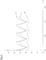
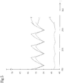
- FIGS. 3 to 6 illustrated temperature profiles exemplified.
- the diagrams show the temperature T of components, for example the in Fig. 1 represented components 2-1, 2-2, over time t.
- the temperature profiles shown there can be detected by temperature sensors, for example, the in Fig. 1 represented temperature sensors 3-1, 3-2 recorded.
- Fig. 3 shows an exemplary temperature profile T (t) in a welder 1 with working cooling at an ambient temperature of 40 ° C.
- this has a relation to the ambient temperature slightly elevated relatively constant temperature of, for example, about 42 ° C, as in Fig. 3 represented by curve III.
- the curves I, II show the temperature profile of two components within the welding apparatus 1, for example, the components 2-1, 2-2 in Fig. 1 , How to get in Fig. 3 can recognize the temperature profile is periodic in both components 2-i, the operating temperature during a welding period increases and drops during a subsequent welding break.
- Fig. 4 shows the temperature curves T (t) at an elevated ambient temperature of 50 ° C with functioning cooling of the welding device 1.
- the ambient temperature is reported for example by the ambient temperature sensor 9 of the monitoring unit 5.
- the curves of the curves I to III are as in Fig. 3 , but shifted upwards by the value of the higher ambient temperature.
- the temperature in normal operation is about 55 ° C.
- Fig. 5 shows the temperature curves T (t) at the two components 2-1, 2-2 at an ambient temperature of 40 ° C with blocked cooling air supply. How to get out Fig. 5 can recognize the temperature T within the welding device 1 outside the cooling air path 8 within the housing of the welding device 1 slightly above the temperature profile in Fig. 3 (Curve III), while the temperature profiles reported by the temperature sensors 3-1, 3-2 of the two components 2-1, 2-2 are both significantly increased. This is a clear indication that the cooling air supply is blocked within the cooling section 8 within the welding device 1 due to a faulty fan 6. Due to the faulty fan 6, the temperature curves T (t) of the two components 2-1, 2-2 (curve I, curve II) contained in the cooling air section 8 shift in parallel upward.
- Fig. 6 shows the temperature curves T (t) at an ambient temperature of 40 ° C after the occurrence of another error.
- curve I the temperature profile, which is transmitted from the sensor 3-1 of the first component 2-1 to the monitoring unit 5, in comparison to the temperature profile according to Fig. 3 clearly increased.
- the temperature fluctuations on the first component 2-1 are significantly larger compared to the temperature fluctuations on the other component 2-2 (curve II).
- the monitoring unit 5 close to a fault in the cooling unit of the first component 2-1 (curve I). If this component 2-1 has, for example, a heat sink which is screwed to the component 2-1, it can be made of the in Fig.
- the monitoring unit 5 can carry out the analysis of the different temperature profiles T (t) taking into account the ambient temperature T U and the currently delivered welding power in order to detect possible deviations from a normal operating state of the cooling.
- an analysis can be made by analyzing the temperature profiles T (t), the ambient temperature T U (t), the rotational speed of the fan 6 and / or the output welding current I according to the welding power possible causes of faults are responsible for the temperature variations that have occurred.
- the cooling times can also be recorded. From the cooling time of the operating state of the cooling can be determined or derived. For example, reference values can be stored for this purpose.
- the monitoring unit 5 can sort different possible causes of error according to their probability and display them to the user via the user interface 11.
- the monitoring unit 5 has access to an internal or external data memory, which contains a data model of the welding device 1.
- This data model preferably specifies the components contained in the welding apparatus 1 and preferably their spatial position along the cooling air path 8.
- the monitoring unit 5 can refine the analysis of the temperature profiles T (t) reported to it, as it emerges from the data model how the relative position of the various components 2-i is within the cooling air gap 8.
- the occurring operating state deviations of the cooling and the analysis results can be reported in a possible embodiment of the monitoring unit 5 via the network interface 12 of a central control system of a plant to cause the necessary maintenance.
- the monitoring unit 5 can detect a wide variety of error causes or operating state deviations, for example, that the supply of cooling air in the cooling air path 8 is blocked or a heat sink in the welding machine 1 is occupied or dirty. Further possible error states or causes of errors are, for example, an excessively high ambient temperature T U in the environment of the welding device 1 or that individual cooling units are defective or impaired. This makes it possible for the maintenance personnel to preventively perform a maintenance of the cooling of the welding device 1 before critical limit temperatures are reached at the affected component 2-i within the welding device 1. If the ambient temperature is too high, the maintenance personnel can ensure sufficient cooling of the ambient air of the welding power source. This has the consequence that an unwanted failure of the welding device 1 can be preventively avoided within the system, so that the productivity of the system is increased.
- error states or causes of errors are, for example, an excessively high ambient temperature T U in the environment of the welding device 1 or that individual cooling units are defective or impaired.
- the life of the various components 2-i within of the welding apparatus 1 is increased by avoiding too high temperatures.
- the monitoring unit 5 can also selectively control actuators within the welding device 1 in order to avoid consequences of the error that has occurred. If, for example, the monitoring unit 5 detects on the basis of the temperature profiles reported to it that the local cooling unit of the component 2-1 within the cooling section 8 is faulty or has completely failed, it can control the fan 6 for the transitional correction or alleviation of the error such that the cooling of the affected component 2-1 is increased. For example, the speed of the fan 6 can be increased to the maximum value.
- the monitoring unit 5 can then operate the fan 6 again normally.
- a message can also be sent to the user / operator so that he carries out a targeted check of the affected component 2-1.
- measures for troubleshooting such as tightening screw connections to heat sinks or removing local contamination.
- soiling can also be removed, for example, by changing the running direction of the fan 6.
- compressed air or a protective gas required for the welding process can also be blown through a filter by means of an actuator so that it is cleaned and more supply air can be sucked in again.
- the temperature sensors 3-1, 3-2 can also be arranged such that they detect a temperature at the inlet and at the outlet of the cooling air plug 8 of the cooling air L. It can also be used for additional temperature sensors. From this, a heat balance can be determined by the monitoring unit 5 and conclusions drawn on possible errors. For this, a data model, reference values, etc. can be used - as already described.
- Fig. 2 shows a flowchart for illustrating an embodiment of the inventive method for monitoring an operating state of a device cooling in a device, for example, the in Fig. 1 illustrated welding machine 1.
- a first step S1 an operating temperature curve T (t) of at least one component 2-i of the device 1 is detected.
- step S2 the operating state of the device cooling is determined on the basis of the at least one detected operating temperature profile and a power provided by the device 1.
- the detected operating temperature curves T (t) of the components for detecting at least one potential cause of the operating state deviation of the device cooling in a possible embodiment of the method according to the invention are analyzed in step S3.
- the operating state deviation of the device cooling and at least one detected potential cause of the operating state deviation is output via a user interface or a network interface of the device 1 in step S4.
- instructions for eliminating the corresponding cause via the user interface and / or the network interface to a user or a central controller are preferably output in step S4.
- the monitoring unit 5 can carry out a check as to whether the corresponding maintenance measure has led to a correction of the operating state deviation of the device cooling and thus the maintenance measure was successful.
- the illustrated method is preferably executed by a monitoring program that runs on a microprocessor of the monitoring unit 5.
- This monitoring program can be loaded in a possible embodiment via the network interface 12 of the device 1 in a program memory of the monitoring unit 5.
- the corresponding monitoring program is loaded via a network from a server which is operated, for example, by the manufacturer of the device 1.
- the monitoring unit 5 in another possible embodiment has a further data memory for storing the data model of the components or assemblies contained in the device 1.
- this data model of the device 1 can likewise be downloaded via the network interface 12 from a database or a server.
- the loaded data model can take into account different configurations or variants of the device 1.
- the monitoring unit 5 is integrated in the device 1.
- the monitoring unit 5 may also be integrated in a central control of a system which is connected via a network to one or more devices 1.
- the central control of the system can dynamically adapt various maintenance plans for various devices, in particular welding devices 1, in accordance with the reported temperature profiles and operating state deviations of the device cooling systems. In one possible embodiment, this is in Fig. 1 illustrated device 1 in a plant, such as a manufacturing plant integrated.
- the device 1 may also be a mobile portable device for mobile use.
- the device 2 is an energy device that provides electrical power in the form of DC or AC power.
- the device 1 is a welding device, as shown schematically in FIG Fig. 1 is shown.
- the device 1 is a battery charger or inverter of a photovoltaic system for converting DC into AC.
Landscapes
- Engineering & Computer Science (AREA)
- Physics & Mathematics (AREA)
- Mechanical Engineering (AREA)
- General Physics & Mathematics (AREA)
- Automation & Control Theory (AREA)
- Plasma & Fusion (AREA)
- Optics & Photonics (AREA)
- Microelectronics & Electronic Packaging (AREA)
- Theoretical Computer Science (AREA)
- Thermal Sciences (AREA)
- Human Computer Interaction (AREA)
- Manufacturing & Machinery (AREA)
- Cooling Or The Like Of Electrical Apparatus (AREA)
- Testing And Monitoring For Control Systems (AREA)
- Cooling Or The Like Of Semiconductors Or Solid State Devices (AREA)
- Rectifiers (AREA)
- Measuring Temperature Or Quantity Of Heat (AREA)
- Arc Welding Control (AREA)
Claims (11)
- Appareil (1) destiné à fournir une puissance électrique, l'appareil (1) comportant :des capteurs de température (3-1, 3-2) intégrés, qui détectent des variations de température de fonctionnement de composants (2-1, 2-2) de l'appareil (1) etune unité de surveillance (5), qui surveille l'état de fonctionnement d'un refroidissement de l'appareil (1) sur la base des variations de température de fonctionnement détectées et de la puissance, caractérisé en ce quele refroidissement de l'appareil (1) comporte au moins une unité de ventilation (6) comme composant, qui alimente de l'air de refroidissement depuis l'environnement de l'appareil (1) dans d'autres composants (2-1, 2-2) de l'appareil (1) le long d'une voie d'air de refroidissement (8) située à l'intérieur d'un boîtier de l'appareil (1), l'unité de surveillance (5) ayant accès à une mémoire de données interne ou externe, dans laquelle est enregistré un modèle de données des composants (2-1, 2-2, 6) compris dans l'appareil (1) et de leur position dans l'espace le long de la voie d'air de refroidissement (8), l'unité de surveillance (5) étant conçue pour, en cas d'écart de l'état de fonctionnement surveillé du refroidissement par rapport à un état de fonctionnement normal du refroidissement, analyser les variations de température de fonctionnement détectées de différents composants (2-1, 2-2) pour déterminer au moins une cause potentielle de l'écart entre les états de fonctionnement, l'unité de surveillance (5) prenant en compte le modèle de données enregistré dans la mémoire de données.
- Appareil selon la revendication 1, dans lequel au moins un autre capteur de température (9) détecte la température ambiante dans l'environnement de l'appareil (1) et la transmet à l'unité de surveillance (5) de l'appareil (1).
- Appareil selon la revendication 1 ou 2, dans lequel l'appareil (1) comporte une interface utilisateur (11), qui comporte une unité d'affichage destinée à afficher l'écart entre les états de fonctionnement du refroidissement, la cause déterminée de l'écart entre les états de fonctionnement et des instructions pour éliminer la cause déterminée de l'écart entre les états de fonctionnement du refroidissement.
- Appareil selon la revendication 3, dans lequel l'interface utilisateur (11) comporte une unité d'entrée destinée au réglage du courant par un utilisateur et/ou par une commande centrale d'une installation.
- Appareil selon l'une des revendications précédentes 1 à 4, dans lequel les composants (2-1, 2-2) de l'appareil (1) sont des composants électroniques et/ou électromécaniques, des unités de refroidissement associées étant prévues pour le refroidissement du composant (2-1, 2-2) respectif.
- Appareil selon l'une des revendications précédentes 1 à 5, dans lequel des composants (2-1, 2-2) le long de la voie d'air de refroidissement (8) comportent des capteurs de température (3-1, 3-2) associés, qui détectent une variation de température de fonctionnement sur les composants (2-1, 2-2) respectifs et la transmettent à l'unité de surveillance (5) de l'appareil (1).
- Appareil selon l'une des revendications précédentes 1 à 6, dans lequel une unité de mesure du courant (10) de l'appareil (1) mesure le courant réglé et le transmet à l'unité de surveillance (5).
- Appareil selon l'une des revendications précédentes 1 à 7, dans lequel l'unité de surveillance (5) commande une unité de refroidissement et/ou l'unité de ventilation (6) en fonction de l'état de fonctionnement actuel du refroidissement.
- Appareil selon l'une des revendications précédentes 1 à 8, dans lequel l'unité de surveillance (5) transmet l'état de fonctionnement du refroidissement à une commande centrale d'une installation par le biais d'une interface réseau (12) de l'appareil (1).
- Procédé de surveillance d'un état de fonctionnement d'un refroidissement pour un appareil (1), comprenant les étapes consistant à :(a) détecter (S1) une variation de température de fonctionnement de composants (2) de l'appareil (1) et(b) déterminer (S2) l'état de fonctionnement du refroidissement sur la base des variations de température de fonctionnement détectées et d'une puissance électrique fournie par l'appareil (1) ;(c) analyser (S3) les variations de température de fonctionnement détectées des composants (2) en cas d'écart de l'état de fonctionnement déterminé du refroidissement par rapport à un état de fonctionnement normal du refroidissement pour identifier au moins une cause potentielle de l'écart entre les états de fonctionnement du refroidissement, un modèle de données enregistré des composants (2) compris dans l'appareil (1) et de leur position dans l'espace le long d'une voie d'air de refroidissement (8) étant pris en compte.
- Procédé selon la revendication 10, dans lequel un écart entre les états de fonctionnement du refroidissement et au moins une cause potentielle détectée de l'écart entre les états de fonctionnement ainsi que des instructions pour éliminer la cause correspondante sont sortis (S4) par le biais d'une interface utilisateur (11) et/ou d'une interface réseau (12) de l'appareil (1).
Priority Applications (1)
| Application Number | Priority Date | Filing Date | Title |
|---|---|---|---|
| PL16730786T PL3308231T3 (pl) | 2015-06-15 | 2016-06-13 | Urządzenie z nadzorowanym chłodzeniem |
Applications Claiming Priority (2)
| Application Number | Priority Date | Filing Date | Title |
|---|---|---|---|
| EP15172103.2A EP3106951A1 (fr) | 2015-06-15 | 2015-06-15 | Appareil doté d'un refroidissement surveillé |
| PCT/EP2016/063463 WO2016202726A1 (fr) | 2015-06-15 | 2016-06-13 | Appareil à refroidissement surveillé |
Publications (2)
| Publication Number | Publication Date |
|---|---|
| EP3308231A1 EP3308231A1 (fr) | 2018-04-18 |
| EP3308231B1 true EP3308231B1 (fr) | 2019-09-18 |
Family
ID=53433070
Family Applications (2)
| Application Number | Title | Priority Date | Filing Date |
|---|---|---|---|
| EP15172103.2A Withdrawn EP3106951A1 (fr) | 2015-06-15 | 2015-06-15 | Appareil doté d'un refroidissement surveillé |
| EP16730786.7A Active EP3308231B1 (fr) | 2015-06-15 | 2016-06-13 | Appareil doté d'un refroidissement surveillé |
Family Applications Before (1)
| Application Number | Title | Priority Date | Filing Date |
|---|---|---|---|
| EP15172103.2A Withdrawn EP3106951A1 (fr) | 2015-06-15 | 2015-06-15 | Appareil doté d'un refroidissement surveillé |
Country Status (10)
| Country | Link |
|---|---|
| US (1) | US10610951B2 (fr) |
| EP (2) | EP3106951A1 (fr) |
| JP (1) | JP6707567B2 (fr) |
| CN (1) | CN107710088B (fr) |
| AU (1) | AU2016278742B2 (fr) |
| BR (1) | BR112017026943B1 (fr) |
| ES (1) | ES2762980T3 (fr) |
| MX (1) | MX367228B (fr) |
| PL (1) | PL3308231T3 (fr) |
| WO (1) | WO2016202726A1 (fr) |
Families Citing this family (9)
| Publication number | Priority date | Publication date | Assignee | Title |
|---|---|---|---|---|
| US10695876B2 (en) | 2013-05-23 | 2020-06-30 | Crc-Evans Pipeline International, Inc. | Self-powered welding systems and methods |
| US11767934B2 (en) | 2013-05-23 | 2023-09-26 | Crc-Evans Pipeline International, Inc. | Internally welded pipes |
| US10589371B2 (en) | 2013-05-23 | 2020-03-17 | Crc-Evans Pipeline International, Inc. | Rotating welding system and methods |
| US10480862B2 (en) * | 2013-05-23 | 2019-11-19 | Crc-Evans Pipeline International, Inc. | Systems and methods for use in welding pipe segments of a pipeline |
| AU2015308646A1 (en) | 2014-08-29 | 2017-02-09 | Crc-Evans Pipeline International Inc. | Method and system for welding |
| US11458571B2 (en) | 2016-07-01 | 2022-10-04 | Crc-Evans Pipeline International, Inc. | Systems and methods for use in welding pipe segments of a pipeline |
| US20180185948A1 (en) * | 2017-01-04 | 2018-07-05 | Illinois Tool Works Inc. | Methods and systems for visually displaying thermal duty cycles |
| US20200034923A1 (en) * | 2018-07-27 | 2020-01-30 | John Martin | Application and website that facilitates Cash Loans |
| CN111200919B (zh) * | 2018-11-19 | 2022-04-01 | 中国移动通信集团内蒙古有限公司 | 冷源ba控制系统和数据中心 |
Family Cites Families (20)
| Publication number | Priority date | Publication date | Assignee | Title |
|---|---|---|---|---|
| JP3053304B2 (ja) * | 1992-10-28 | 2000-06-19 | ヤンマーディーゼル株式会社 | 内燃機関の故障予知装置 |
| DE19626059A1 (de) | 1996-06-28 | 1998-01-02 | Manfred Heberle | Schweißvorrichtung |
| US7145760B2 (en) | 2000-12-15 | 2006-12-05 | Abb Technology Ltd. | Tap changer monitoring |
| BRPI0116200B8 (pt) * | 2000-12-15 | 2022-11-22 | Abb Technology Ltd | Método e dispositivo de diagnóstico para um comutador de derivação tendo um líquido isolante |
| US6906630B2 (en) | 2001-02-28 | 2005-06-14 | General Electric Company | Transformer management system and method |
| JP3606230B2 (ja) * | 2001-05-31 | 2005-01-05 | 日本電気株式会社 | 給排気口異常検出機能を備える装置および給排気口異常検出方法 |
| JP3699676B2 (ja) * | 2001-11-29 | 2005-09-28 | ダイセル化学工業株式会社 | プラント制御監視装置 |
| JP3930822B2 (ja) * | 2003-03-13 | 2007-06-13 | 村松風送設備工業株式会社 | 燃焼排煙処理プラントの遠隔監視システム |
| DE102005058351A1 (de) * | 2005-12-06 | 2007-06-14 | Alia Technik Gmbh | Verfahren und Vorrichtung zum Überwachen eines Schweißinverters |
| DE102005060635A1 (de) * | 2005-12-13 | 2007-06-14 | Siemens Ag | Steuerungsverfahren zur Kühlung einer technischen Anlage |
| US7765818B2 (en) * | 2006-05-30 | 2010-08-03 | B/E Aerospace, Inc. | Refrigeration unit and diagnostic method therefor |
| JP5175622B2 (ja) * | 2008-05-30 | 2013-04-03 | 株式会社東芝 | 電子機器 |
| JP5218280B2 (ja) * | 2009-05-21 | 2013-06-26 | 富士通株式会社 | 監視装置、監視プログラムおよび監視方法 |
| GB2484428B (en) | 2009-07-31 | 2014-12-10 | Hewlett Packard Development Co | Commissioning of sensors |
| US8185862B2 (en) * | 2010-07-13 | 2012-05-22 | Algotochip Corporation | Architectural level power-aware optimization and risk mitigation |
| US20130346926A1 (en) | 2010-07-13 | 2013-12-26 | Algotochip Corporation | Automatic optimal integrated circuit generator from algorithms and specification |
| DE102012013104A1 (de) * | 2012-06-30 | 2013-01-17 | Daimler Ag | Temperaturvorhersagevorrichtung und Überwachungsvorrichtung, sowie Verfahren zur Vorhersage einer Solltemperatur |
| US9092030B2 (en) * | 2013-03-14 | 2015-07-28 | Rockwell Automation Technologies, Inc. | Method to implement drive diagnostics and prognostics automatically |
| JP5950024B2 (ja) * | 2013-03-18 | 2016-07-13 | 富士通株式会社 | 情報処理装置、情報処理方法、及び情報処理プログラム |
| US9521780B2 (en) * | 2014-12-18 | 2016-12-13 | Dell Products L.P. | Regulation of airflow and performance in information handling systems after fan failure |
-
2015
- 2015-06-15 EP EP15172103.2A patent/EP3106951A1/fr not_active Withdrawn
-
2016
- 2016-06-13 JP JP2017564826A patent/JP6707567B2/ja active Active
- 2016-06-13 CN CN201680035279.4A patent/CN107710088B/zh active Active
- 2016-06-13 MX MX2017016238A patent/MX367228B/es active IP Right Grant
- 2016-06-13 ES ES16730786T patent/ES2762980T3/es active Active
- 2016-06-13 WO PCT/EP2016/063463 patent/WO2016202726A1/fr not_active Ceased
- 2016-06-13 EP EP16730786.7A patent/EP3308231B1/fr active Active
- 2016-06-13 PL PL16730786T patent/PL3308231T3/pl unknown
- 2016-06-13 AU AU2016278742A patent/AU2016278742B2/en active Active
- 2016-06-13 BR BR112017026943-0A patent/BR112017026943B1/pt active IP Right Grant
- 2016-06-13 US US15/580,673 patent/US10610951B2/en active Active
Non-Patent Citations (1)
| Title |
|---|
| None * |
Also Published As
| Publication number | Publication date |
|---|---|
| JP2018517988A (ja) | 2018-07-05 |
| US10610951B2 (en) | 2020-04-07 |
| BR112017026943B1 (pt) | 2022-12-06 |
| ES2762980T3 (es) | 2020-05-26 |
| MX367228B (es) | 2019-08-09 |
| PL3308231T3 (pl) | 2020-03-31 |
| US20180185951A1 (en) | 2018-07-05 |
| MX2017016238A (es) | 2018-04-20 |
| CN107710088A (zh) | 2018-02-16 |
| JP6707567B2 (ja) | 2020-06-10 |
| AU2016278742B2 (en) | 2018-12-06 |
| AU2016278742A1 (en) | 2018-01-04 |
| WO2016202726A1 (fr) | 2016-12-22 |
| BR112017026943A2 (fr) | 2018-08-21 |
| EP3308231A1 (fr) | 2018-04-18 |
| EP3106951A1 (fr) | 2016-12-21 |
| CN107710088B (zh) | 2020-07-03 |
Similar Documents
| Publication | Publication Date | Title |
|---|---|---|
| EP3308231B1 (fr) | Appareil doté d'un refroidissement surveillé | |
| EP3193012B1 (fr) | Agencement destiné à la surveillance d'un parc éolien | |
| AT511971B1 (de) | Verfahren zur überwachung einer kühl- oder heizeinrichtung und überwachungseinrichtung hierzu | |
| DE102017011220B4 (de) | Lüftermotorsteuervorrichtung | |
| DE4234654A1 (de) | Diagnosesystem für Roboter und Anwendungsverfahren dafür | |
| DE102013221273A1 (de) | Verfahren zum Überwachen und Regeln einer Qualität von Schweißpunkten | |
| DE102017203836A1 (de) | Verfahren und System zum Bestimmen einer erwarteten Lebensdauer eines elektrischen Betriebsmittels | |
| EP3289657B1 (fr) | Procede pour controler les chaines de modules solaires dans une installation photovoltaïque et un onduleur photovoltaïque pour l'application de la methode | |
| EP2812970A1 (fr) | Système modulaire d'alimentation redondante en courant cc-cc, doté de sorties aptes au montage en parallèle | |
| EP1193756B1 (fr) | Méthode pour un dispositif avec semi-conducteurs de puissance et un dispositif | |
| DE102020101193A1 (de) | Elektrisches Schutzschaltersystem mit temperaturabhängiger Gesamtstromüberwachung | |
| WO2022218482A1 (fr) | Procédé de surveillance du fonctionnement d'un ventilateur, appareil et ventilateur | |
| EP3100064B1 (fr) | Dispositif et procédé de détection de défauts dans des machines | |
| DE102017220233A1 (de) | Schweisssteuerung für eine schweissanlage, schweissanlage und schweissverfahren zur regelung einer qualität einer herstellung einer schweissverbindung | |
| EP3997021A1 (fr) | Système et procédé de surveillance d'état lors du fonctionnement d'un système d'acheminement | |
| EP4185932B1 (fr) | Surveillance d'un convertisseur | |
| DE102018101010B4 (de) | Echtzeit Monitoring eines Mehrzonen-Vertikalofens mit frühzeitiger Erkennung eines Ausfalls eines Heizzonen-Elements | |
| EP4285459A1 (fr) | Système d'alimentation électrique | |
| EP4226494A1 (fr) | Procédé de surveillance d'un ou de plusieurs entraînements électriques d'un système électromécanique | |
| EP3306329B1 (fr) | Procédé de surveillance centrale de changements d'état d'une pluralité de composants pour installations haute tension à partir de 1 kv. | |
| EP2163337B1 (fr) | Dispositif de soudage ou de brasage à consommation réduite | |
| DE102005058351A1 (de) | Verfahren und Vorrichtung zum Überwachen eines Schweißinverters | |
| DE202021100210U1 (de) | Retrofit-Vorrichtung | |
| DE102012020438A1 (de) | Verfahren zur Prüfung einer elektrischen Verbindung zwischen zwei Energiespeichereinheiten einer Batterieanordnung und Batterieanordnung | |
| DE102009041404A1 (de) | Eigensicherer Transformator |
Legal Events
| Date | Code | Title | Description |
|---|---|---|---|
| STAA | Information on the status of an ep patent application or granted ep patent |
Free format text: STATUS: THE INTERNATIONAL PUBLICATION HAS BEEN MADE |
|
| PUAI | Public reference made under article 153(3) epc to a published international application that has entered the european phase |
Free format text: ORIGINAL CODE: 0009012 |
|
| STAA | Information on the status of an ep patent application or granted ep patent |
Free format text: STATUS: REQUEST FOR EXAMINATION WAS MADE |
|
| 17P | Request for examination filed |
Effective date: 20171219 |
|
| AK | Designated contracting states |
Kind code of ref document: A1 Designated state(s): AL AT BE BG CH CY CZ DE DK EE ES FI FR GB GR HR HU IE IS IT LI LT LU LV MC MK MT NL NO PL PT RO RS SE SI SK SM TR |
|
| AX | Request for extension of the european patent |
Extension state: BA ME |
|
| DAV | Request for validation of the european patent (deleted) | ||
| DAX | Request for extension of the european patent (deleted) | ||
| GRAP | Despatch of communication of intention to grant a patent |
Free format text: ORIGINAL CODE: EPIDOSNIGR1 |
|
| STAA | Information on the status of an ep patent application or granted ep patent |
Free format text: STATUS: GRANT OF PATENT IS INTENDED |
|
| RIC1 | Information provided on ipc code assigned before grant |
Ipc: G05B 23/02 20060101AFI20190328BHEP Ipc: B23K 9/10 20060101ALI20190328BHEP Ipc: H05K 7/20 20060101ALI20190328BHEP Ipc: B23K 1/00 20060101ALI20190328BHEP Ipc: B23K 37/00 20060101ALI20190328BHEP Ipc: B23K 9/095 20060101ALI20190328BHEP |
|
| INTG | Intention to grant announced |
Effective date: 20190417 |
|
| GRAS | Grant fee paid |
Free format text: ORIGINAL CODE: EPIDOSNIGR3 |
|
| GRAA | (expected) grant |
Free format text: ORIGINAL CODE: 0009210 |
|
| STAA | Information on the status of an ep patent application or granted ep patent |
Free format text: STATUS: THE PATENT HAS BEEN GRANTED |
|
| AK | Designated contracting states |
Kind code of ref document: B1 Designated state(s): AL AT BE BG CH CY CZ DE DK EE ES FI FR GB GR HR HU IE IS IT LI LT LU LV MC MK MT NL NO PL PT RO RS SE SI SK SM TR |
|
| REG | Reference to a national code |
Ref country code: GB Ref legal event code: FG4D Free format text: NOT ENGLISH |
|
| REG | Reference to a national code |
Ref country code: CH Ref legal event code: EP |
|
| REG | Reference to a national code |
Ref country code: DE Ref legal event code: R096 Ref document number: 502016006695 Country of ref document: DE |
|
| REG | Reference to a national code |
Ref country code: AT Ref legal event code: REF Ref document number: 1182065 Country of ref document: AT Kind code of ref document: T Effective date: 20191015 |
|
| REG | Reference to a national code |
Ref country code: IE Ref legal event code: FG4D Free format text: LANGUAGE OF EP DOCUMENT: GERMAN |
|
| REG | Reference to a national code |
Ref country code: SE Ref legal event code: TRGR |
|
| REG | Reference to a national code |
Ref country code: NL Ref legal event code: MP Effective date: 20190918 |
|
| PG25 | Lapsed in a contracting state [announced via postgrant information from national office to epo] |
Ref country code: LT Free format text: LAPSE BECAUSE OF FAILURE TO SUBMIT A TRANSLATION OF THE DESCRIPTION OR TO PAY THE FEE WITHIN THE PRESCRIBED TIME-LIMIT Effective date: 20190918 Ref country code: BG Free format text: LAPSE BECAUSE OF FAILURE TO SUBMIT A TRANSLATION OF THE DESCRIPTION OR TO PAY THE FEE WITHIN THE PRESCRIBED TIME-LIMIT Effective date: 20191218 Ref country code: HR Free format text: LAPSE BECAUSE OF FAILURE TO SUBMIT A TRANSLATION OF THE DESCRIPTION OR TO PAY THE FEE WITHIN THE PRESCRIBED TIME-LIMIT Effective date: 20190918 Ref country code: NO Free format text: LAPSE BECAUSE OF FAILURE TO SUBMIT A TRANSLATION OF THE DESCRIPTION OR TO PAY THE FEE WITHIN THE PRESCRIBED TIME-LIMIT Effective date: 20191218 |
|
| REG | Reference to a national code |
Ref country code: LT Ref legal event code: MG4D |
|
| PG25 | Lapsed in a contracting state [announced via postgrant information from national office to epo] |
Ref country code: GR Free format text: LAPSE BECAUSE OF FAILURE TO SUBMIT A TRANSLATION OF THE DESCRIPTION OR TO PAY THE FEE WITHIN THE PRESCRIBED TIME-LIMIT Effective date: 20191219 Ref country code: RS Free format text: LAPSE BECAUSE OF FAILURE TO SUBMIT A TRANSLATION OF THE DESCRIPTION OR TO PAY THE FEE WITHIN THE PRESCRIBED TIME-LIMIT Effective date: 20190918 Ref country code: AL Free format text: LAPSE BECAUSE OF FAILURE TO SUBMIT A TRANSLATION OF THE DESCRIPTION OR TO PAY THE FEE WITHIN THE PRESCRIBED TIME-LIMIT Effective date: 20190918 Ref country code: LV Free format text: LAPSE BECAUSE OF FAILURE TO SUBMIT A TRANSLATION OF THE DESCRIPTION OR TO PAY THE FEE WITHIN THE PRESCRIBED TIME-LIMIT Effective date: 20190918 |
|
| PG25 | Lapsed in a contracting state [announced via postgrant information from national office to epo] |
Ref country code: RO Free format text: LAPSE BECAUSE OF FAILURE TO SUBMIT A TRANSLATION OF THE DESCRIPTION OR TO PAY THE FEE WITHIN THE PRESCRIBED TIME-LIMIT Effective date: 20190918 Ref country code: PT Free format text: LAPSE BECAUSE OF FAILURE TO SUBMIT A TRANSLATION OF THE DESCRIPTION OR TO PAY THE FEE WITHIN THE PRESCRIBED TIME-LIMIT Effective date: 20200120 Ref country code: EE Free format text: LAPSE BECAUSE OF FAILURE TO SUBMIT A TRANSLATION OF THE DESCRIPTION OR TO PAY THE FEE WITHIN THE PRESCRIBED TIME-LIMIT Effective date: 20190918 Ref country code: NL Free format text: LAPSE BECAUSE OF FAILURE TO SUBMIT A TRANSLATION OF THE DESCRIPTION OR TO PAY THE FEE WITHIN THE PRESCRIBED TIME-LIMIT Effective date: 20190918 |
|
| REG | Reference to a national code |
Ref country code: ES Ref legal event code: FG2A Ref document number: 2762980 Country of ref document: ES Kind code of ref document: T3 Effective date: 20200526 |
|
| PG25 | Lapsed in a contracting state [announced via postgrant information from national office to epo] |
Ref country code: CZ Free format text: LAPSE BECAUSE OF FAILURE TO SUBMIT A TRANSLATION OF THE DESCRIPTION OR TO PAY THE FEE WITHIN THE PRESCRIBED TIME-LIMIT Effective date: 20190918 Ref country code: SK Free format text: LAPSE BECAUSE OF FAILURE TO SUBMIT A TRANSLATION OF THE DESCRIPTION OR TO PAY THE FEE WITHIN THE PRESCRIBED TIME-LIMIT Effective date: 20190918 Ref country code: IS Free format text: LAPSE BECAUSE OF FAILURE TO SUBMIT A TRANSLATION OF THE DESCRIPTION OR TO PAY THE FEE WITHIN THE PRESCRIBED TIME-LIMIT Effective date: 20200224 Ref country code: SM Free format text: LAPSE BECAUSE OF FAILURE TO SUBMIT A TRANSLATION OF THE DESCRIPTION OR TO PAY THE FEE WITHIN THE PRESCRIBED TIME-LIMIT Effective date: 20190918 |
|
| REG | Reference to a national code |
Ref country code: DE Ref legal event code: R097 Ref document number: 502016006695 Country of ref document: DE |
|
| PLBE | No opposition filed within time limit |
Free format text: ORIGINAL CODE: 0009261 |
|
| STAA | Information on the status of an ep patent application or granted ep patent |
Free format text: STATUS: NO OPPOSITION FILED WITHIN TIME LIMIT |
|
| PG2D | Information on lapse in contracting state deleted |
Ref country code: IS |
|
| PG25 | Lapsed in a contracting state [announced via postgrant information from national office to epo] |
Ref country code: DK Free format text: LAPSE BECAUSE OF FAILURE TO SUBMIT A TRANSLATION OF THE DESCRIPTION OR TO PAY THE FEE WITHIN THE PRESCRIBED TIME-LIMIT Effective date: 20190918 Ref country code: IS Free format text: LAPSE BECAUSE OF FAILURE TO SUBMIT A TRANSLATION OF THE DESCRIPTION OR TO PAY THE FEE WITHIN THE PRESCRIBED TIME-LIMIT Effective date: 20200119 |
|
| 26N | No opposition filed |
Effective date: 20200619 |
|
| PG25 | Lapsed in a contracting state [announced via postgrant information from national office to epo] |
Ref country code: SI Free format text: LAPSE BECAUSE OF FAILURE TO SUBMIT A TRANSLATION OF THE DESCRIPTION OR TO PAY THE FEE WITHIN THE PRESCRIBED TIME-LIMIT Effective date: 20190918 |
|
| PG25 | Lapsed in a contracting state [announced via postgrant information from national office to epo] |
Ref country code: MC Free format text: LAPSE BECAUSE OF FAILURE TO SUBMIT A TRANSLATION OF THE DESCRIPTION OR TO PAY THE FEE WITHIN THE PRESCRIBED TIME-LIMIT Effective date: 20190918 |
|
| REG | Reference to a national code |
Ref country code: CH Ref legal event code: PL |
|
| GBPC | Gb: european patent ceased through non-payment of renewal fee |
Effective date: 20200613 |
|
| PG25 | Lapsed in a contracting state [announced via postgrant information from national office to epo] |
Ref country code: LU Free format text: LAPSE BECAUSE OF NON-PAYMENT OF DUE FEES Effective date: 20200613 |
|
| REG | Reference to a national code |
Ref country code: BE Ref legal event code: MM Effective date: 20200630 |
|
| PG25 | Lapsed in a contracting state [announced via postgrant information from national office to epo] |
Ref country code: IE Free format text: LAPSE BECAUSE OF NON-PAYMENT OF DUE FEES Effective date: 20200613 Ref country code: GB Free format text: LAPSE BECAUSE OF NON-PAYMENT OF DUE FEES Effective date: 20200613 Ref country code: CH Free format text: LAPSE BECAUSE OF NON-PAYMENT OF DUE FEES Effective date: 20200630 Ref country code: LI Free format text: LAPSE BECAUSE OF NON-PAYMENT OF DUE FEES Effective date: 20200630 |
|
| PG25 | Lapsed in a contracting state [announced via postgrant information from national office to epo] |
Ref country code: BE Free format text: LAPSE BECAUSE OF NON-PAYMENT OF DUE FEES Effective date: 20200630 |
|
| PG25 | Lapsed in a contracting state [announced via postgrant information from national office to epo] |
Ref country code: TR Free format text: LAPSE BECAUSE OF FAILURE TO SUBMIT A TRANSLATION OF THE DESCRIPTION OR TO PAY THE FEE WITHIN THE PRESCRIBED TIME-LIMIT Effective date: 20190918 Ref country code: MT Free format text: LAPSE BECAUSE OF FAILURE TO SUBMIT A TRANSLATION OF THE DESCRIPTION OR TO PAY THE FEE WITHIN THE PRESCRIBED TIME-LIMIT Effective date: 20190918 Ref country code: CY Free format text: LAPSE BECAUSE OF FAILURE TO SUBMIT A TRANSLATION OF THE DESCRIPTION OR TO PAY THE FEE WITHIN THE PRESCRIBED TIME-LIMIT Effective date: 20190918 |
|
| PG25 | Lapsed in a contracting state [announced via postgrant information from national office to epo] |
Ref country code: MK Free format text: LAPSE BECAUSE OF FAILURE TO SUBMIT A TRANSLATION OF THE DESCRIPTION OR TO PAY THE FEE WITHIN THE PRESCRIBED TIME-LIMIT Effective date: 20190918 |
|
| P01 | Opt-out of the competence of the unified patent court (upc) registered |
Effective date: 20230525 |
|
| REG | Reference to a national code |
Ref country code: DE Ref legal event code: R082 Ref document number: 502016006695 Country of ref document: DE Representative=s name: BRATOVIC, NINO, DR. RER. NAT., DE |
|
| PGFP | Annual fee paid to national office [announced via postgrant information from national office to epo] |
Ref country code: FI Payment date: 20250624 Year of fee payment: 10 |
|
| PGFP | Annual fee paid to national office [announced via postgrant information from national office to epo] |
Ref country code: PL Payment date: 20250603 Year of fee payment: 10 Ref country code: DE Payment date: 20250626 Year of fee payment: 10 |
|
| PGFP | Annual fee paid to national office [announced via postgrant information from national office to epo] |
Ref country code: FR Payment date: 20250624 Year of fee payment: 10 |
|
| PGFP | Annual fee paid to national office [announced via postgrant information from national office to epo] |
Ref country code: AT Payment date: 20250617 Year of fee payment: 10 |
|
| PGFP | Annual fee paid to national office [announced via postgrant information from national office to epo] |
Ref country code: SE Payment date: 20250619 Year of fee payment: 10 |
|
| PGFP | Annual fee paid to national office [announced via postgrant information from national office to epo] |
Ref country code: ES Payment date: 20250710 Year of fee payment: 10 |
|
| PGFP | Annual fee paid to national office [announced via postgrant information from national office to epo] |
Ref country code: IT Payment date: 20250623 Year of fee payment: 10 |