EP3308595B1 - Aufbau einer interaktionssitzung auf einem träger in einem funkkommunikationsnetz - Google Patents
Aufbau einer interaktionssitzung auf einem träger in einem funkkommunikationsnetz Download PDFInfo
- Publication number
- EP3308595B1 EP3308595B1 EP15735751.8A EP15735751A EP3308595B1 EP 3308595 B1 EP3308595 B1 EP 3308595B1 EP 15735751 A EP15735751 A EP 15735751A EP 3308595 B1 EP3308595 B1 EP 3308595B1
- Authority
- EP
- European Patent Office
- Prior art keywords
- address information
- communication
- bearer
- ran
- service
- Prior art date
- Legal status (The legal status is an assumption and is not a legal conclusion. Google has not performed a legal analysis and makes no representation as to the accuracy of the status listed.)
- Active
Links
Images


Classifications
-
- H—ELECTRICITY
- H04—ELECTRIC COMMUNICATION TECHNIQUE
- H04W—WIRELESS COMMUNICATION NETWORKS
- H04W36/00—Hand-off or reselection arrangements
- H04W36/0005—Control or signalling for completing the hand-off
- H04W36/0011—Control or signalling for completing the hand-off for data sessions of end-to-end connection
- H04W36/0027—Control or signalling for completing the hand-off for data sessions of end-to-end connection for a plurality of data sessions of end-to-end connections, e.g. multi-call or multi-bearer end-to-end data connections
-
- H—ELECTRICITY
- H04—ELECTRIC COMMUNICATION TECHNIQUE
- H04W—WIRELESS COMMUNICATION NETWORKS
- H04W28/00—Network traffic management; Network resource management
- H04W28/02—Traffic management, e.g. flow control or congestion control
- H04W28/0252—Traffic management, e.g. flow control or congestion control per individual bearer or channel
- H04W28/0263—Traffic management, e.g. flow control or congestion control per individual bearer or channel involving mapping traffic to individual bearers or channels, e.g. traffic flow template [TFT]
-
- H—ELECTRICITY
- H04—ELECTRIC COMMUNICATION TECHNIQUE
- H04W—WIRELESS COMMUNICATION NETWORKS
- H04W76/00—Connection management
- H04W76/10—Connection setup
-
- H—ELECTRICITY
- H04—ELECTRIC COMMUNICATION TECHNIQUE
- H04W—WIRELESS COMMUNICATION NETWORKS
- H04W76/00—Connection management
- H04W76/10—Connection setup
- H04W76/11—Allocation or use of connection identifiers
-
- H—ELECTRICITY
- H04—ELECTRIC COMMUNICATION TECHNIQUE
- H04W—WIRELESS COMMUNICATION NETWORKS
- H04W76/00—Connection management
- H04W76/10—Connection setup
- H04W76/12—Setup of transport tunnels
-
- H—ELECTRICITY
- H04—ELECTRIC COMMUNICATION TECHNIQUE
- H04W—WIRELESS COMMUNICATION NETWORKS
- H04W76/00—Connection management
- H04W76/20—Manipulation of established connections
- H04W76/22—Manipulation of transport tunnels
-
- H—ELECTRICITY
- H04—ELECTRIC COMMUNICATION TECHNIQUE
- H04W—WIRELESS COMMUNICATION NETWORKS
- H04W76/00—Connection management
- H04W76/10—Connection setup
- H04W76/15—Setup of multiple wireless link connections
Definitions
- the present disclosure relates to methods and devices for establishing a communication session between a radio device and a Radio Access Network (RAN).
- RAN Radio Access Network
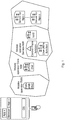
- FIG. 1 is a simplified network illustration.
- the App x and App y in the User Equipment (UE) communicates with their respective server located on the Internet via the mobile operators Radio Access Network (RAN), Core Network (CN) and service network.
- RAN Radio Access Network
- CN Core Network
- service network To take the Adaptive Bit Rate feature as an example, for this feature the video server has the video encoded in different bitrates, and the UE selects the format based on throughput estimations.
- End user experience or Quality of Experience (QoE) is a differentiator for mobile operators and internet service providers.
- Applications are attempting to be adaptive to ensure a good QoE, e.g. by adapting to varying throughput by changing to an encoded format with a suitable bitrate.
- FIG 2 is a schematic diagram of Evolved Packet Core (EPC) architecture (non-roaming) for access to a cellular network in accordance with a Third Generation Partnership Project (3GPP) standard.
- Evolved Packet System (EPS) is the Evolved 3GPP Packet Switched Domain and consists of EPC and an Evolved Universal Terrestrial Radio Access Network (E-UTRAN).
- the architecture is defined in 3GPP Technical Specification (TS) 23.401 V13.2.0(2015-03-12 ), which also defines the Packet Data Network (PDN) Gateway PGW, the Serving Gateway (SGW), the Policy and Charging Rules Function (PCRF), the Mobility Management Entity (MME) and the user equipment (UE, a radio device e.g. a mobile phone).
- PDN Packet Data Network
- SGW Serving Gateway
- PCRF Policy and Charging Rules Function
- MME Mobility Management Entity
- UE user equipment
- UE user equipment
- LTE Long Term Evolution
- E-UTRAN comprises one or more base stations called evolved Node B (eNB).
- the E-UTRAN comprises eNBs providing the E-UTRAN user plane (radio interface user plane layers such as Packet Data Convergence Protocol (PDCP), Radio Link Control (RLC), Media Access Control (MAC) and physical layer (PHY)) and control plane (Radio Resource Control, RRC, in addition to the above user plane protocol layers) protocol terminations towards the UE.
- the eNBs are interconnected with each other over the X2 interface.
- the eNBs are also connected by means of the S1 interface to the EPC, more specifically to the MME over the S1-MME interface and to the SGW over the S1-U interface.
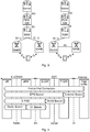
- LTE Dual Connectivity As the name implies it means that a UE can be connected to multiple eNBs at the same time, i.e. send and receive data on multiple paths as illustrated in figure 3 (showing two different options for user plane handling of LTE DC).
- E-UTRAN supports DC operation whereby a UE comprising multiple receivers and transmitters (RX/TX) in RRC_CONNECTED state is configured to utilise radio resources provided by two distinct schedulers, located in two different eNBs connected via a non-ideal backhaul over the X2 interface.
- eNB Master eNB
- SeNB Secondary eNB
- MCG Master Cell Group
- SCG Secondary Cell Group
- QoS Quality of Service
- the RAN is responsible for setting up the radio bearers, radio resource management, and enforcing QoS according to the bearer QoS Profile - over the radio (e.g. LTE-Uu) interface in the downlink (DL) and over the transport network in the uplink (UL).
- the architectures differ slightly over the different radio access networks (e.g. 3G/Wideband Code Division Multiple Access (WCDMA) and 4G/LTE) but the QoS principles are similar (at least for 3G and 4G networks).
- Figure 4 shows the EPS bearer architecture and the different levels of bearers building up the end-to-end connection for the UE.
- a PDN is in most cases an IP network, e.g. Internet or an operator IP Multimedia Subsystem (IMS) service network.
- a PDN has one or more names. Each name is defined in a string called Access Point Name (APN).
- the PGW is a gateway towards one or more PDNs.
- a UE may have one or more PDN connections.
- a PDN connection is a logical IP tunnel between UE and PGW, providing the UE access to a PDN.
- the setup of a PDN connection is initiated from the UE. Every PDN connection consists of one or more EPS bearers. See 3GPP TS 23.401 V13.2.0 (2015-03-12 ) section 4.7.2 for a description of the bearer concept.
- a bearer uniquely identifies traffic flows that receive a common QoS treatment between a UE and a PGW.
- Each bearer on a particular access has a unique bearer ID.
- the bearer On the 3GPP access, the bearer is end-to-end between UE and PGW. Every PDN connection has at least one bearer and this bearer is called the default bearer. All additional bearers on the PDN connection are called dedicated bearers.
- a bearer carries traffic in the form of IP packets. Which traffic is carried on a bearer is defined by filters.
- a filter is an n-tuple where each element in the tuple contains a value, a range, or a wildcard.
- An n-tuple is also known as an IP flow.
- This 5-tuple defines a source (src) and destination (dst) IP address, a source and destination port, and a protocol.
- TCP Transmission Control Protocol
- a traffic flow template contains one or more filters. Every bearer has a TFT.
- One bearer within a PDN connection and access may lack an explicit TFT (this bearer is typically the default bearer). Implicitly such a bearer has a TFT with a single filter matching all packets.
- Bearers are used for example to provide different quality of service and characteristics.
- a UE When a UE is active it has a default bearer where all traffic goes.
- the network or the UE can initiate a secondary/dedicated bearer with a different quality/characteristics.
- the network can detect a flow that should have a dedicated bearer by inspecting the traffic, or the network can be informed by an Application Function (AF), with reference to Figure 2 , an entity in the operators IP services, or the network can be informed by the UE about the need for a dedicated bearer. For example, if a video session is detected.
- the network then could trigger the establishment of a new bearer, apply a filter to separate which traffic should go on which bearer, i.e. the TFT.
- AF Application Function
- TFT is also sent to the UE so that the UE can put UL traffic on the correct bearer.
- TFTs are used to map/select which transport tunnel (GTP tunnel) and bearer a certain flow should be sent on.
- GTP tunnel transport tunnel
- a TFT can comprise the following identifiers:
- the PGW will, when receiving an IP packet from Internet with destination IP address, select a UE context based on the destination IP address. This means that the UE context is identified with an UE IP address and contains a number of TFTs associated for each dedicated bearer established for the UE. The PGW then checks if there is a TFT associated with information included in the received IP packet in the UE context and try to match the received IP packet with the TFT, and if there is a match send the packet on the dedicated bearer associated with that TFT. Similarly for the UE, when an UL packet is sent from the higher layer parts of the UE, e.g. an app, and received by the lower layer of the UE, e.g. where the radio protocols reside, there is a check if there is a TFT that matches and if there is match then the UL packet is sent on the dedicated bearer associated with that TFT.
- the UE when an UL packet is sent from the higher layer parts of the UE, e.g. an app, and received
- US 2014/003394 A1 described improved capabilities for increasing the bandwidth in a large area broadband LTE wireless network, where regional optimization servers are incorporated near the wireless network in association with the public data network gateway, thus reducing the time-latency for applications being run from a mobile cellular device.
- 3GPP TS 23.401 V13.2.0 (2015-03-12), "3rd Generation Partnership Project; Technical Specification Group Services and System Aspects; General Packet Radio Service (GPRS) enhancements for Evolved Universal Terrestrial Radio Access Network (E-UTRAN) access (Release 13) " describes the Evolved 3GPP Packet Switched Domain which provides IP connectivity using the Evolved Universal Terrestrial Radio Access Network (E-UTRAN).
- GPRS General Packet Radio Service
- 3GPP TS 23.060 V13.2.0 (2015-03-12), "3rd Generation Partnership Project; Technical Specification Group Services and System Aspects; General Packet Radio Service (GPRS); Service description; Stage 2 (Release 13) " describes the General Packet Radio Service (GPRS) which is a packet bearer service and a main part of the packet domain.
- GPRS General Packet Radio Service
- the present disclosure is related to providing new functionality in existing (2G, 3G, 4G etc.) and future RAN (5G, 6G, etc.).
- the area of functionality comprises interactions between the service domain and RAN domain, for example between an app running on a radio device and a RAN node such as an eNB.
- Service applications are attempting to be adaptive to ensure a good QoE, e.g. by adapting to varying throughputs by changing the bit rate or resolution of a streaming video and/or audio to avoid freezing of the play-out.
- this is done by trying to estimate the throughput between server and application in the radio device, e.g. based on measured link bit rate or round trip times (RTT).
- RTT round trip times
- the estimation is typically performed by the application in the radio device, i.e. the service client (herein also called "client").
- client An interface between the mobile network and the client could be used to convey information that can be used to enhance service delivery and QoE.
- the interaction communication should preferably be possible to relate to the dedicated bearer of the service, since for example the achievable bitrate may depend on the priority of the bearer.
- NW network
- IGW Interaction Gateway
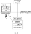
- An Ii-interface is introduced between the radio device and the Interaction Gateway.
- the Interaction Gateway may have another interface, called an I2-interface, towards the RAN depending on the position of the Interaction Gateway.
- the Interaction Gateway can be placed either in the RAN (see figure 5 ) or at the SGi interface. In the following, it is assumed that the IGW is in the RAN.
- the Ii-interface may be defined based on user plane traffic. It may for example be User Datagram Protocol (UDP)/Internet Protocol (IP)-based so that the client (app) in the radio device is able to send and receive interaction messages.
- UDP User Datagram Protocol
- IP Internet Protocol
- the intention is that a single IP address may be used by the RAN nodes in one operators network for the interaction. This may simplify Operations and Maintenance (O&M) and RAN handling.
- O&M Operations and Maintenance
- the presence of this IP address (called RAN IP address, which may be part of default IGW address information) may thus be an indication of an interaction session message for the RAN.
- the client in the radio device can for example obtain this IP address by a Domain Name System (DNS) lookup. Additional measures may be needed since RAN does not normally terminate user plane traffic.
- DNS Domain Name System
- an interaction message When an interaction message is identified, it may only be forwarded to the Interaction Gateway (i.e. not towards the core network).
- the Interaction Gateway in RAN wants to send an interaction message to the radio device, it is injected in the downlink traffic by the RAN.
- network assistance which aims to improve QoE
- the client in the radio device sends a query message to the RAN node asking for the available bitrate. This query is handled by the Interaction Gateway which interacts with a Function for Recommendation, wherein an achievable bit rate is estimated or predicted for the radio device.
- a response message may be sent back to the radio device.
- the achievable bitrate may depend on a number of factors, e.g. number of radio devices in the cell that needs to share the capacity, the radio conditions of the radio device, and the priority for the bearer.
- the user plane based interaction interface (Ii) may have some issues if dedicated bearers are used and the UE-NW interactions are related to the session on the dedicated bearer. These issues are hereby exemplified:
- an initial radio device - RAN interaction on the default bearer the RAN selects dedicated IGW address information, e.g. a termination port, for this I1 interaction session and replies with that to the radio device. If a second Ii interaction session is initiated by the radio device, it is sent on the default bearer and when the RAN detects the new Ii initiation it selects a second dedicated IGW address information, e.g. termination port for the second I1 session. Then, either the NW or the radio device may ensure that the Ii signalling is directed to the same bearer as the service it relates to.
- dedicated IGW address information e.g. a termination port
- the radio device by means of the service client, during the initial interaction may also inform the RAN about service level address information e.g. destination addresses used by the service.
- the RAN may then communicate the received information about the service level address information, the used default IGW address information and the determined dedicated IGW address information for service client -RAN interaction to an Application Function (AF) that can communicate with the PCRF (Alternatively the RAN could act as an AF and implement the Rx interface).
- AF Application Function
- the AF may then instruct the PCRF via the Rx interface to ensure that a filter (exemplified as a TFT) is added for the dedicated IGW address information for the bearer associated with the service and identified with the destination addresses used by the service (i.e. there exists a TFT for at least parts of the destination addresses used by the service for the bearer associated with the service).
- the PCRF ensures this by signalling the received information to the PGW (over the Gx interface).
- the PGW may then initiate a bearer modification procedure resulting in that the radio device also receives the updated UL TFT for the dedicated IGW address information for the bearer associated with the service.
- the radio device may, when receiving the dedicated IGW address information that should be used, initiate a procedure for radio device requested bearer resource modification towards the CN, indicating that a TFT for the dedicated IGW address information should be added for the dedicated bearer in question.
- This procedure if accepted and supported by the NW, may lead to that the CN sends information about the added TFT also to the radio device as per normal procedures.
- This option may require that the service client (app) in the radio device has an internal Application Programming Interface (API) to activate this functionality, i.e. that the client is bearer aware and has requested a dedicated bearer initially.
- API Application Programming Interface
- the radio device could have an API to add this filter locally, e.g., when receiving the dedicated IGW address information from the RAN, the client could instruct the lower layers of the radio device to install the TFT filter with the dedicated IGW address information for the bearer.
- the interaction session is for controlling the service level communication on the second bearer, e.g. a dedicated bearer dedicated to the service of the service provider, it would be advantageous to have also the interaction session on the second bearer rather than on the first bearer. Otherwise, the RAN may have difficulties determining what service level communication the interaction session relates to, since the RAN may not know which bearer is for which service (the RAN usually only forwarding data on the different bearers). By means of the dedicated IGW address information, the RAN knows which data on the second bearer is part of the interaction session and that it relates to the service level communication.
- the present disclosure provides methods to ensure that the interaction session over the Ii interface is on the same bearer as the related service is running on.
- the RAN selects the dedicated IGW address information (e.g. a termination port for) this Ii session and replies with that to the radio device. If a second Ii interaction session is initiated by the client, it is again sent on the first bearer and when RAN detects a new Ii initiation it selects a second dedicated IGW address information (e.g. termination port and/or an IP address to the RAN allowing the RAN to identify data addressed to it which should not be forwarded on the bearer) for the second Ii interaction session. Then either the network or the radio device can ensure that the signalling of the interaction session over Ii is directed to the same bearer as the service it relates to.
- the dedicated IGW address information e.g. a termination port for
- This present disclosure provides methods to relate client-RAN interaction, Ii interaction, to the corresponding bearer that carries the service which the interaction relates to, and by that making it possible for the RAN to make recommendations for a specific bearer, i.e. service. Additionally, the methods allow the RAN to make multiple Ii recommendations, one per each bearer.
- Embodiments of the present disclosure provides methods to facilitate that interaction messages will be sent on the dedicated bearer the interaction relates to. This may be done by ensuring that a filter/TFT including the dedicated IGW address information (e.g. RAN IP address and/or termination port) is used to identify interaction messages sent to the radio device on the dedicated bearer the interaction relates to.
- a filter/TFT including the dedicated IGW address information e.g. RAN IP address and/or termination port
- the general assumption in the following description of example embodiments is that there exists a default bearer and at least one dedicated bearer for the radio device.
- the dedicated bearer is used for a specific service for which the radio device is about to establish the interaction session over Ii. Some embodiments may also function in the case when the radio device has multiple dedicated bearers for different services and a separate Ii interaction session is to be established for each service.
- the client may send an Ii Initialization Message on the default bearer addressed to the RAN by means of default IGW address information.
- the default IGW address information may comprise an IP address or an UDP port, or both.
- the IP address may be a so called RAN IP address.
- the client in the radio device sends this message, the lower layers in the radio device typically sends this message on the default bearer since the destination IP (the RAN IP) is not part of any TFT for a dedicated bearer.
- the RAN when receiving this message may select an UDP port as dedicated IGW address information, and return this to the client with an I1 Confirmation Message, if service interaction supported and accepted.
- a further step may then be to add a TFT for the dedicated IGW address information (e.g. RAN IP and/or selected termination (UDP) port), so that the bearer handling in the radio device will send uplink packets with dedicated IGW address information to the correct dedicated bearer, i.e. the bearer for the related service.
- a TFT for the dedicated IGW address information (e.g. RAN IP and/or selected termination (UDP) port)
- UDP selected termination
- FIG. 6 is a schematic block diagram of a radio device 4 connected to a communication network 1.
- the communication network 1 comprises a RAN 2, typically a cellular RAN in accordance with a 3GPP standard, comprising one or a plurality of RAN nodes 3, e.g. evolved Node B (eNB) or Node B in combination with Radio Network Controller (RNC).
- the communication network 1 also comprises a CN 5 comprising an SGW 7 and a PGW 8 as well as an MME 6 and a PCRF 11, and any other standard CN nodes needed.
- the PCRF is also connected with an AF 12 in accordance with some embodiments of the present disclosure.
- the communication network is connected to the PDN 9, e.g. the Internet, in which a service provider (SP) 10 resides with one or a plurality of servers e.g. Content Delivery Network (CDN) servers.
- SP service provider
- CDN Content Delivery Network
- the radio device 4 may be any device or user equipment (UE), mobile or stationary, enabled to communicate over a radio channel in a communication network 1, for instance but not limited to e.g. mobile phone, smart phone, modem, sensors, meters, vehicles (e.g. a car), household appliances, medical appliances, media players, cameras, or any type of consumer electronic, for instance but not limited to television, radio, lighting arrangements, tablet computer, laptop, or personal computer (PC).
- UE user equipment
- FIG. 7a schematically illustrates an embodiment of a RAN node 3 of the present disclosure.
- the RAN node 3 comprises processor circuitry 71 e.g. a central processing unit (CPU).
- the processor circuitry 71 may comprise one or a plurality of processing units in the form of microprocessor(s). However, other suitable devices with computing capabilities could be comprised in the processor circuitry 71, e.g. an application specific integrated circuit (ASIC), a field programmable gate array (FPGA) or a complex programmable logic device (CPLD).
- the processor circuitry 71 is configured to run one or several computer program(s) or software (SW) 91 (see also figure 9 ) stored in a storage 73 of one or several storage unit(s) e.g. a memory.
- SW software
- the interaction gateway may be formed in the processor circuitry 71 by SW 91 stored in the storage 73 running on the processor circuitry 71.
- the storage unit is regarded as a computer readable means 93 (see figure 9 ) as discussed herein and may e.g. be in the form of a Random Access Memory (RAM), a Flash memory or other solid state memory, or a hard disk, or be a combination thereof.
- the processor circuitry 71 may also be configured to store data in the storage 73, as needed.
- the RAN node 3 also comprises a communication interface 74 for communication with other nodes in the communication network 1 as well as with the radio device over a radio interface.
- the communication interface comprises a transmitter and a receiver, which may be combined into a transceiver, as well as an antenna for radio communication.
- the RAN node comprises the IGW 72, processor circuitry 71, and a storage unit 73 storing instructions 91 executable by said processor circuitry whereby said RAN node is operative to obtain an initialization message addressed to the RAN 2 by means of default IGW address information on the first bearer, for initiating the interaction session, the initialization message comprising service level address information used for the service level communication on the service provider side.
- the RAN node is also operative to determine dedicated IGW address information for the interaction session.
- the RAN node is also operative to initiate sending of a confirmation message comprising the determined dedicated IGW address information to the service client 82.
- the RAN node is also operative to ensure that the interaction session, using the dedicated IGW address information, is associated with the second communication bearer used for the service level communication.
- the RAN node is also operative to obtain an interaction session message addressed to the RAN 2 by means of the determined dedicated IGW address information on the second communication bearer.
- the RAN node is also operative to initiate sending a response to the interaction session message, to the service client 82 in the radio device 4 on the second bearer.
- Figure 7b is a schematic block diagram functionally illustrating an embodiment of the RAN node 3 in figure 7a .
- the processor circuitry 71 may run software 91 for enabling the RAN node 3 to perform an embodiment of a method of the present disclosure, whereby functional modules may be formed in RAN node 3 e.g. in the processor circuitry 71 for performing the different steps of the method. These modules are schematically illustrated as blocks within the RAN node 3.
- the RAN node 3 comprises a receiving module 75 for obtaining an initialization message addressed to the RAN 2 by means of default IGW address information on the first bearer, for initiating the interaction session, the initialization message comprising service level address information used for the service level communication on the service provider side; and for obtaining an interaction session message addressed to the RAN 2 by means of the determined dedicated IGW address information on the second communication bearer.
- the messages may be obtained by e.g. receiving them directly from the radio device 4 or via another RAN node 3.
- the RAN node 3 also comprises a determining module 76 for determining dedicated IGW address information for the interaction session.
- the RAN node also comprises a sending module 77 for initiating sending of a confirmation message comprising the determined dedicated IGW address information to the service client, and for initiating sending a response to the interaction session message, to the service client 82 in the radio device 4 on the second bearer.
- the RAN node also comprises an ensuring module 78 for ensuring that the interaction session, using the dedicated IGW address information, is associated with the second communication bearer used for the service level communication.
- FIG 8a schematically illustrates an embodiment of a radio device 4 of the present disclosure.
- the radio device 4 comprises processor circuitry 81 e.g. a central processing unit (CPU).
- the processor circuitry 81 may comprise one or a plurality of processing units in the form of microprocessor(s). However, other suitable devices with computing capabilities could be comprised in the processor circuitry 81, e.g. an application specific integrated circuit (ASIC), a field programmable gate array (FPGA) or a complex programmable logic device (CPLD).
- ASIC application specific integrated circuit
- FPGA field programmable gate array
- CPLD complex programmable logic device
- the processor circuitry 81 is configured to run one or several computer program(s) or software (SW) 92 (see also figure 9 ) stored in a storage 83 of one or several storage unit(s) e.g. a memory.
- SW software
- the service client 82 (e.g. a service application, an app) may be formed in the processor circuitry 71 by client SW 92a stored in the storage 83 running on the processor circuitry 81.
- the storage unit is regarded as a computer readable means 93 (see figure 9 ) as discussed herein and may e.g. be in the form of a Random Access Memory (RAM), a Flash memory or other solid state memory, or a hard disk, or be a combination thereof.
- the processor circuitry 81 may also be configured to store data in the storage 83, as needed.
- the radio device 4 also comprises a radio communication interface 84 for communication with/via the communication network 1 e.g. via the RAN node 3.
- the radio interface comprises a transmitter and a receiver, which may be combined into a transceiver, as well as an antenna for radio communication.
- a radio device 4 for being connected to a RAN 2 of a communication network 1 in which there is a first and a second communication bearer between the radio device and a CN 5 of the communication network via the RAN, where the second communication bearer is associated with the service level communication, and for establishing an interaction session between an IGW 72 of the RAN and the service client in the radio device on the second communication bearer for controlling the service level communication.
- the radio device comprises a service client 82 configured for service level communication with a service provider, processor circuitry 81, and a storage unit 83 storing instructions 92 executable by said processor circuitry whereby said radio device is operative to obtain dedicated IGW address information for the interaction session.
- the radio device is also operative to ensure that the interaction session, using the dedicated IGW address information, is associated with the second communication bearer used for the service level communication.
- FIG 8b is a schematic block diagram functionally illustrating an embodiment of the radio device 4 in figure 8a .
- the processor circuitry 81 may run software 92 for enabling the radio device 4 to perform an embodiment of a method of the present disclosure, whereby functional modules may be formed in the radio device 4 e.g. in the processor circuitry 81 for performing the different steps of the method. These modules are schematically illustrated as blocks within the radio device 4.
- the radio device 4 comprises an obtaining module 85 for obtaining dedicated IGW address information for the interaction session, and an ensuring module 86 for ensuring that the interaction session, which session uses the dedicated IGW address information, is associated with the second communication bearer used for the service level communication.
- Figure 9 illustrates a computer program product 90.
- the computer program product 90 comprises a computer readable (e.g. non-volatile and/or non-transitory) medium 93 comprising a computer program 91 and/or 92 in the form of computer-executable components 91/92.
- the computer program/computer-executable components 91/92 may be configured to cause a RAN node 3 or a radio device 4, e.g. as discussed herein, to perform an embodiment of a method of the present disclosure.
- the computer program/computer-executable components may be run on the processor circuitry 71/81 of the RAN node 3/radio device 4 for causing it to perform the method.
- the computer program product 90 may e.g.
- the computer program product 90 may be, or be part of, a separate, e.g. mobile, storage means/medium, such as a computer readable disc, e.g. CD or DVD or hard disc/drive, or a solid state storage medium, e.g. a RAM or Flash memory.
- a separate, e.g. mobile, storage means/medium such as a computer readable disc, e.g. CD or DVD or hard disc/drive, or a solid state storage medium, e.g. a RAM or Flash memory.
- the storage medium 93 can include, but are not limited to, any type of disk including floppy disks, optical discs, DVD, CD-ROMs, microdrive, and magneto-optical disks, ROMs, RAMs, EPROMs, EEPROMs, DRAMs, VRAMs, flash memory devices, magnetic or optical cards, nanosystems (including molecular memory ICs), or any type of media or device suitable for storing instructions and/or data.
- Embodiments of the present disclosure may be conveniently implemented using one or more conventional general purpose or specialized digital computer, computing device, machine, or microprocessor, including one or more processors, memory and/or computer readable storage media programmed according to the teachings of the present disclosure. Appropriate software coding can readily be prepared by skilled programmers based on the teachings of the present disclosure, as will be apparent to those skilled in the software art.
- a computer program product 90 comprising computer-executable components 91 for causing a RAN node 3 or a radio device 4 to perform an embodiment of a method of the present disclosure when the computer-executable components are run on processor circuitry 71/81 comprised in the RAN node/radio device.
- a computer program 91 for establishing an interaction session between an IGW of a RAN and a service client of a radio device for controlling service level communication between the service client and a service provider, wherein there is a first and a second communication bearer between the radio device and a CN via the RAN, where the second communication bearer is associated with the service level communication.
- the computer program comprises computer program code which is able to, when run on processor circuitry 71 of a RAN node 3, cause the RAN node to obtain S1 an initialization message addressed to the RAN by means of default IGW address information on the first bearer, for initiating the interaction session, the initialization message comprising service level address information used for the service level communication on the service provider side.
- the code is also able to cause the RAN node to determine S2 dedicated IGW address information for the interaction session.
- the code is also able to cause the RAN node to initiate S3 sending of a confirmation message comprising the determined dedicated IGW address information to the service client.
- the code is also able to cause the RAN node to ensure S4 that the interaction session, using the dedicated IGW address information, is associated with the second communication bearer used for the service level communication.
- the code is also able to cause the RAN node to obtain S5 an interaction session message addressed to the RAN by means of the determined dedicated IGW address information and associated with the service level communication, on the second communication bearer.
- the code is also able to cause the RAN node to initiate S6 sending a response to the interaction session message, to the service client in the radio device on the second bearer.
- a computer program 92 for establishing an interaction session between an IGW of a RAN and service client of a radio device for controlling service level communication between the service client and a service provider, wherein there is a first and a second communication bearer between the radio device and a CN via the RAN, where the second communication bearer is associated with the service level communication.
- the computer program comprises computer program code which is able to, when run on processor circuitry 81 of the radio device 4, cause the radio device to obtain S11 dedicated IGW address information for the interaction session.
- the code is also able to cause the radio device to ensure S12 that the interaction session, using the dedicated IGW address information, is associated with the second communication bearer used for the service level communication.
- a computer program product 90 comprising an embodiment of a computer program 91/92 of the present disclosure and a computer readable means 93 on which the computer program is stored.
- Figure 10 schematically illustrates some signalling between different nodes in accordance with the present disclosure.
- a first (default) bearer 106 and a second (dedicated) bearer 107 are set up between the radio device 4 and the CN 5 via the RAN node 3.
- messages relating to the interaction session 103 is addressed to the RAN, by means of the default IGW address information 105 (on the default bearer 106) or the dedicated IGW address information 104 (on the dedicated bearer 107)
- these messages are picked up by the RAN node 3 instead of being forwarded to the CN on the respective bearer 106 or 107.
- the service level communication 101 from/to the service client 82 is addressed by means of the service level address information 102, e.g.
- the interaction session 103 from the service client 82 is set up to the IGW 72 by means of the initialization message with the default IGW address information 105 on the default bearer 106. Then, the interaction session uses the dedicated IGW address information 104 on the dedicated bearer 107.
- DNS Domain Name System
- Figure 11 is a schematic flow chart of an embodiment of the method performed in the RAN 2.
- the method may be performed in a RAN node 3 e.g. in an RNC or in an eNB of the RAN 2.
- An initialization message addressed to the RAN 2 by means of default IGW address information 105 on the first bearer 106 is obtained Si, e.g. by receiving the message directly or indirectly (via another part of the RAN 2) from the radio device 4.
- the initialization message is for initiating the interaction session 103 between the service client 82 and the IGW 72.
- the initialization message comprises service level address information 102 used for the service level communication 101 on the service provider side.
- the service level address information 102 may be used by the RAN 2 to identify the service level communication 101 and the second bearer 107 carrying the service level communication 101.
- the default IGW address information may e.g. be an (IP) address to the RAN (in general) or to the IGW 72 (in particular).
- the dedicated IGW address information 104 may e.g. be a port number (e.g. UDP port number) to be used for identifying data of the interaction session as it is sent on the second bearer 107.
- a port number e.g. UDP port number
- the RAN initiates S3 sending of a confirmation message comprising the determined S2 dedicated IGW address information 104 to the service client 82 in the radio device 4. That the RAN initiates sending implies that a RAN node 3 sends the confirmation message to the radio device 4, but it need not be the same RAN node 3 that sends the message as determines S2 the dedicated IGW address information 104 and initiates S3 the confirmation message.
- the RAN 2 ensures S4 that the interaction session 103, which session uses the dedicated IGW address information 104, is associated with the second communication bearer 107 used for the service level communication 101. This implies that data/messages of the interaction session are transmitted over the second communication bearer 107, which is the same bearer over which the service level communication 101 is transmitted.
- the ensuring S4 further comprises initiating setting up of a filter (e.g. TFT) in the radio device 4 for mapping Internet Protocol (IP) data packets associated with the determined dedicated IGW address information 104 to the second communication bearer 107, after the determining S2 of the dedicated IGW address information and before the obtaining S5 of the interaction session message.
- a filter e.g. TFT
- the ensuring S4 comprises initiating sending a message comprising the determined S2 dedicated IGW address information 103 as well as the service level address information 102 to an Application Function (AF), for initiating setting up of a filter in the CN 5 for mapping IP data packets associated with the determined dedicated IGW address information 104 to the second communication bearer 107.
- the AF may e.g. communicate with the PCRF for setting up the filter (e.g. TFT) in the PGW.
- the RAN obtains S5 an interaction session message addressed to the RAN 2 by means of the determined S2 dedicated IGW address information 104 on the second communication bearer 107.
- the interaction session message may be obtained e.g. by receiving the message directly or indirectly (via another part of the RAN 2) from the radio device 4.
- the message comprises the determined S2 dedicated IGW address information 104 (e.g. as destination address/port) whereby the RAN 2 may identify the message as being part of the interaction session and may take the message from the second bearer 107 to the IGW 72.
- the RAN 2 initiates S6 sending of a response to the interaction session message.
- the response is sent/addressed to the service client 82 in the radio device 4 on the second bearer 107. That the RAN initiates sending implies that a RAN node 3 sends the response message to the radio device 4, but it need not be the same RAN node 3 that sends the message as determines S2 the dedicated IGW address information 104 and initiates S6 the response message.
- Figure 12 is a schematic flow chart of an embodiment of the method performed in the radio device 4.
- the radio device 4 obtaining S11 dedicated IGW address information 104 for the interaction session 103.
- the obtaining S11 comprises, in conformity with the corresponding method embodiments of figure 11 , sending an initialization message addressed to the RAN 2 by means of default IGW address information 105 on the first communication bearer 106, for initiating the interaction session 103; and receiving a confirmation message from the RAN 2, the message comprising the dedicated IGW address information 104 for the interaction session.
- the obtaining S11 may comprise selecting the dedicated IGW address information 104 for the interaction session (i.e. the radio device selects the dedicated IGW address information 104).
- the radio device 4 ensures S12 that the interaction session 103, which interaction session uses the dedicated IGW address information 104, is associated with (i.e. is sent on) the second communication bearer 107 used for the service level communication 101.
- the ensuring S12 comprises including the service level address information 102 in the initialization message 131 for facilitating the RAN to further provide information e.g. to other network nodes to identify the service level communication 101 and the second bearer 107 on which the service level communication is transmitted.
- the ensuring S12 further comprises updating a filter (e.g. TFT) for the second communication bearer 107, which bearer is used by the service level communication 101, with the dedicated IGW address information 104, thus e.g.
- a filter e.g. TFT
- the ensuring S12 further comprises initiating Request Bearer Resource Modification to the CN 5 to update a filter (e.g. TFT) for the second communication bearer 107 with the dedicated IGW address information 104, thus facilitating the CN 5 adding a TFT to the second bearer both at the CN side and at the radio device side.
- a filter e.g. TFT
- the first communication bearer 106 is a default bearer and the second communication bearer 107 is a dedicated bearer, as exemplified herein.
- the first and second communication bearers 106 and 107 are EPS bearers or Packed Data Protocol (PDP) contexts, depending on the 3GPP standard of the communication network 1.
- PDP Packed Data Protocol
- the filter of the second bearer 107, at the radio device and/or CN side is a Traffic Flow Template (TFT).
- TFT Traffic Flow Template
- other types of filter are also contemplated, depending on the 3GPP standard of the communication network 1.
- the first and second embodiments described below assume that there is an API available in the radio device 4 that the client 82 can use to establish a dedicated bearer, i.e. trigger the lower layers in the radio device to signal this to the CN 5, and that this API also provides an identifier for this bearer to the client that can be used in subsequent bearer modifications, e.g. to add TFTs.
- the client 82 when the client 82 has received the dedicated IGW address information 104 (e.g. an UDP termination port) the client initiates a TFT to be added to the second bearer 107 by instructing the lower layers (using the above mentioned API) to send the existing standard message 'Request Bearer Resource Modification'.
- the radio device includes that the dedicated IGW address information (e.g. RAN IP address and/or the selected UDP termination port) should be part of the TFT.
- the radio device may include the bearer identity for the dedicated bearer 107 and an existing TFT for this bearer or both.
- the network 1 accepts the bearer request, the network will send a new UL TFT to the radio device which comprises the RAN IP and/or the UDP termination port.
- the radio device which comprises the RAN IP and/or the UDP termination port.
- the radio device may implement functionality to locally modify the UL TFT filters, i.e. avoid the signalling to the communication network 1.
- the client 82 that has initiated Ii signalling 103 could send the dedicated IGW address information 104 (e.g. RAN IP and/or selected UDP port)) and the service level address information on an API to the lower layers of the radio device.
- the lower layers in the radio device 4 use the service level address information 102 to identify a bearer (based on lookup on TFTs for all active dedicated bearers). Once the dedicated bearer 107 for the specific service is identified, the lower layers can have the uplink TFT for the dedicated IGW address information added locally in the radio device 4 for the identified bearer.
- the client internal interface may be used as follows. First, the client provides the dedicated IGW address information 104 (e.g. RAN IP and/or selected UDP port) and the service level address information to the lower layers. The lower layers in the radio device 4 use the service level address information 102 to identify a bearer (based on lookup on TFTs for all active dedicated bearers). Once the dedicated bearer 107 for the specific service is identified, the Request Bearer Resource Modification procedure can be triggered in a similar way as for the first embodiment. Finally, the radio device internal interface can be used to indicate to the client 82 the outcome of the lower layer actions.
- the dedicated IGW address information 104 e.g. RAN IP and/or selected UDP port
- the network side can trigger the additional TFT.
- the radio device 4 or client 82 does not support this functionality (e.g. the API discussed in Example 1).
- the radio device would need to send the service level address information 102 (e.g. destination IP address(es) the service is related to) in the Ii Initialization message to the RAN 2.
- the RAN would then interact with an Application function (AF) 12, and provide the service level address information 102 and the dedicated IGW address information 104 (e.g. the RAN IP address and/or the selected UDP termination port).
- AF Application function
- the AF 12 would then instruct the PCRF 11 to ensure that a TFT is added comprising the dedicated IGW address information 104 to the bearer 107 identified by the service level address information, and if needed additional parameters that are required to identify the bearer, e.g. used ports, protocols etc. as available for a TFT.
- the PCRF may ensure this addition of the TFT by signalling the received service level address information 102 and dedicated IGW address information 104 information to the PDN-GW (over the Gx interface).
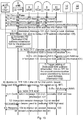
- the PGW may then initiate a bearer modification procedure resulting in that the UE also receives the updated UL TFT for the dedicated IGW address information for the bearer associated with the service. Subsequently UL messages addressed to the dedicated IGW address information are sent on the second bearer 107. This is illustrated in figure 13 .
- Figure 13 shows a simplified communication network 1 for LTE.
- the CN nodes used for control plane signalling such as the MME 6 in case of LTE may be replaced with a Serving GPRS support node (SGSN) in case of Wideband Code Division Multiple Access (WCDMA).
- SGSN Serving GPRS support node
- WCDMA Wideband Code Division Multiple Access
- the RAN 2 is exemplified with an eNB 3, however could alternatively be an other RAN node, such as an RNC.
- a functional entity which may act as an AF in this context, using the Rx interface towards the PCRF is shown.
- the AF is shown as a standalone entity. It could be combined with the RAN 2.
- step 8 could be performed immediately after step 4, and step 10 is optional, etc.
- the list numbering below relates to the step numbers in figure 13 .
Landscapes
- Engineering & Computer Science (AREA)
- Computer Networks & Wireless Communication (AREA)
- Signal Processing (AREA)
- Mobile Radio Communication Systems (AREA)
Claims (15)
- Verfahren, das in einem Funkzugriffsnetzwerk, RAN, (2) eines Kommunikationsnetzwerks (1) durchgeführt wird, das von einem Dienstclient (82) für Dienstebenenkommunikation (101) mit einem Dienstanbieter (10) verwendet wird, wobei es in dem Kommunikationsnetzwerk einen ersten und einen zweiten Kommunikationsträger (106, 107) zwischen einer Funkvorrichtung (4), umfassend den Dienstclient, und einem Kernnetzwerk, CN, (5) des Kommunikationsnetzwerks über das RAN gibt, wobei der zweite Kommunikationsträger (107) mit der Dienstebenenkommunikation verknüpft ist, um eine Interaktionssitzung (103) auf dem zweiten Kommunikationsträger zwischen einem Interaktionsgateway, IGW, (72) des RAN und dem Dienstclient zum Steuern der Dienstebenenkommunikation einzurichten, wobei das Verfahren umfasst:Erhalten (S1) einer Initialisierungsnachricht (131), die mittels Standard-IGW-Adressinformationen (105) an das RAN (2) adressiert ist, auf dem ersten Kommunikationsträger (106), zumInitiieren der Interaktionssitzung (103), wobei die Initialisierungsnachricht Dienstebenenadressinformationen (102) umfasst, die für Dienstebenenkommunikation (101) auf der Dienstanbieterseite verwendet werden;Bestimmen (S2) dedizierter IGW-Adressinformationen (104) für die Interaktionssitzung (103);Initiieren (S3) vom Senden einer Bestätigungsnachricht (132), die die bestimmten (S2) dedizierten IGW-Adressinformationen (104) umfasst, an den Dienstclient (82);Sicherstellen (S4), dass die Interaktionssitzung (103), die die dedizierten IGW-Adressinformationen (104) verwendet, mit dem zweiten Kommunikationsträger (107) verknüpft ist, der für die Dienstebenenkommunikation (101) verwendet wird;Erhalten (S5) einer Interaktionsdienstnachricht (133), die mittels bestimmter (S2) dedizierter IGW-Adressinformationen (104) an das RAN (2) adressiert ist, auf dem zweiten Kommunikationsträger (107); undInitiieren (S6) vom Senden einer Antwort (134) auf die Interaktionssitzungsnachricht (133) an den Dienstclient (82) in der Funkvorrichtung (4) auf dem zweiten Kommunikationsträger (107),wobei das Sicherstellen (S4) Initiieren vom Senden einer Nachricht, die die bestimmten (S2) dedizierten IGW-Adressinformationen (103) wir auch die Dienstebenenadressinformationen (102) umfasst, an eine Anwendungsfunktion umfasst, um Einrichtung eines Filters in dem CN (5) zur Zuordnung von IP-Datenpaketen, die mit den bestimmten dedizierten IGW-Adressinformationen (104) verknüpft sind, zu dem zweiten Kommunikationsträger (107) zu initiieren.
- Verfahren nach Anspruch 1, wobei das Sicherstellen (S4) weiter Initiieren umfasst von
Einrichtung eines Filters (135) in der Funkvorrichtung (4) zur Zuordnung von Internetprotokoll-, IP, Datenpaketen, die mit den bestimmten dedizierten IGW-Adressinformationen (104) verknüpft sind, zu dem zweiten Kommunikationsträger (107), nach dem Bestimmen (S2) der dedizierten IGW-Adressinformationen und vor dem Erhalten (S5) der Interaktionssitzungsnachricht (133). - Verfahren nach einem vorstehenden Anspruch, wobei der erste Kommunikationsträger (106) ein Standardträger ist und der zweite Kommunikationsträger (107) ein dedizierter Träger ist.
- Verfahren nach einem vorstehenden Anspruch, wobei der erste und zweite Kommunikationsträger (106, 107) Entwickeltes-Paketsystem-, EPS, Träger oder Gepacktes-Datenprotokoll-, PDP, Kontexte sind.
- Verfahren nach einem vorstehenden Anspruch, wobei das Filter (135) eine Verkehrsflussvorlage, TFT, ist.
- Verfahren nach einem vorstehenden Anspruch, wobei das Verfahren in einer Funknetzwerksteuerung oder in einem entwickelten Node B, eNB, des RAN (2) durchgeführt wird.
- RAN-Knoten (3) für ein Funkzugriffsnetzwerk, RAN, (2) eines Kommunikationsnetzwerks (1), das von einem Dienstclient (82) für Dienstebenenkommunikation (101) mit einem Dienstanbieter (10) verwendet wird, wobei es in dem Kommunikationsnetzwerk einen ersten und einen zweiten Kommunikationsträger (106, 107) zwischen einer Funkvorrichtung (4) und einem Kernnetzwerk, CN, (5) des Kommunikationsnetzwerks über das RAN gibt, wobei der zweite Kommunikationsträger (107) mit der Dienstebenenkommunikation verknüpft ist, um eine Interaktionssitzung (103) zwischen einem Interaktionsgateway, IGW, (72) und dem Dienstclient auf dem zweiten Kommunikationsträger einzurichten, um die Dienstebenenkommunikation zu steuern, wobei der RAN-Knoten umfasst:das IGW (72);Prozessorschaltkreise (71); undSpeicher (73), der Anweisungen (91) speichert, die von den Prozessorschaltkreisen ausführbar sind, wobei der RAN-Knoten betriebsfähig ist zum:Erhalten einer Initialisierungsnachricht (131), die mittels Standard-IGW-Adressinformationen (105) an das RAN (2) adressiert ist, auf dem ersten Kommunikationsträger (106), zum Initiieren der Interaktionssitzung (103), wobei die Initialisierungsnachricht Dienstebenenadressinformationen (102) umfasst, die für die Dienstebenenkommunikation (101) auf der Dienstanbieterseite verwendet werden;Bestimmen dedizierter IGW-Adressinformationen (104) für die Interaktionssitzung;Initiieren vom Senden einer Bestätigungsnachricht (132), die die bestimmten dedizierten IGW-Adressinformationen (104) umfasst, an den Dienstclient (82);Sicherstellen, dass die Interaktionssitzung (103), unter Verwendung der dedizierten IGW-Adressinformationen (104), mit dem zweiten Kommunikationsträger (107) verknüpft ist, der für die Dienstebenenkommunikation (101) verwendet wird, umfassend Initiieren vom Senden einer Nachricht, die die bestimmten dedizierten IGW-Adressinformationen (103) wie auch die Dienstebenenadressinformationen (102) umfasst, an eine Anwendungsfunktion, zum Initiieren von Einrichtung eines Filters in dem CN (5) zur Zuordnung von IP-Datenpaketen, die mit den bestimmten dedizierten IGW-Adressinformationen (104) verknüpft sind, an den zweiten Kommunikationsträger (107);Erhalten einer Interaktionssitzungsnachricht (133), die mittels bestimmter dedizierter IGW-Adressinformationen (104) an das RAN (2) adressiert ist, auf dem zweiten Kommunikationsträger; undInitiieren vom Senden einer Antwort (134) auf die Interaktionssitzungsnachricht (133), an den Dienstclient (82) in der Funkvorrichtung (4) auf dem zweiten Kommunikationsträger (107).
- Verfahren, das in einer Funkvorrichtung (4) durchgeführt wird, umfassend einen Dienstclient (82), der für Dienstebenenkommunikation (101) mit einem Dienstanbieter (10) konfiguriert ist, der mit einem Funkzugriffsnetzwerk, RAN, (2) eines Kommunikationsnetzwerks (1) verbunden ist, in dem es einen ersten und einen zweiten Kommunikationsträger (106, 107) zwischen der Funkvorrichtung und einem Kernnetzwerk, CN, (5) des Kommunikationsnetzwerks über das RAN gibt, wobei der zweite Kommunikationsträger (107) mit der Dienstebenenkommunikation verknüpft ist, zur Einrichtung einer Interaktionssitzung (103) zwischen einem Interaktionsgateway, IGW, (72) des RAN und dem Dienstclient in der Funkvorrichtung auf dem zweiten Kommunikationsträger, zum Steuern der Dienstebenenkommunikation, wobei das Verfahren umfasst:Erhalten (S11) dedizierter IGW-Adressinformationen (104) für die Interaktionssitzung (103); undSicherstellen (S12), dass die Interaktionssitzung (103) unter Verwendung der dedizierten IGW-Adressinformationen (104) mit dem zweiten Kommunikationsträger (107) verknüpft ist, der für die Dienstebenenkommunikation (101) verwendet wird,dadurch gekennzeichnet, dass das Erhalten (S11) Senden einer Initialisierungsnachricht (131), die mittels Standard-IGW-Adressinformationen (105) an das RAN (2) adressiert ist, auf dem ersten Kommunikationsträger (106), um die Interaktionssitzung (103) zu initiieren, und Empfangen einer Bestätigungsnachricht (132), die die dedizierten IGW-Adressinformationen (104) für die Interaktionssitzung umfasst, von dem RAN (2), umfasst; undwobei das Sicherstellen (S12) umfasst, die Dienstebenenadressinformationen (102) in der Initialisierungsnachricht (131) einzuschließen.
- Verfahren nach Anspruch 8, wobei das Erhalten (S11) weiter umfasst
Auswählen der dedizierten IGW-Adressinformationen (104), die in der Bestätigungsnachricht für die Interaktionssitzung umfasst sind. - Verfahren nach einem von Anspruch 8-9, wobei das Sicherstellen (S12) weiter umfasst
Aktualisieren eines Filters (135) für den zweiten Kommunikationsträger (107), das von der Dienstebenenkommunikation (101) verwendet wird, mit den dedizierten IGW-Adressinformationen (104). - Verfahren nach einem von Anspruch 8-10, wobei das Sicherstellen (S12) weiter umfasst
Initiieren von Anfrageträgerressourcenmodifikation zu dem CN (5), um ein Filter für den zweiten Kommunikationsträger (107), der von der Dienstebenenkommunikation (101) verwendet wird, mit den dedizierten IGW-Adressinformationen (104) zu aktualisieren. - Funkvorrichtung (4), um mit einem Funkzugriffsnetzwerk, RAN, (2) eines Kommunikationsnetzwerks (1) verbunden zu werden, in dem es einen ersten und einen zweiten Kommunikationsträger (106, 107) zwischen der Funkvorrichtung und einem Kernnetzwerk, CN, (5) des Kommunikationsnetzwerks über das RAN gibt, wobei der zweite Kommunikationsträger (107) mit der Dienstebenenkommunikation verknüpft ist, und zur Einrichtung einer Interaktionssitzung (103) zwischen einem Interaktionsgateway, IGW, (72) des RAN und dem Dienstclient in der Funkvorrichtung auf dem zweiten Kommunikationsträger zum Steuern der Dienstebenenkommunikation, wobei die Funkvorrichtung umfasst:einen Dienstclient (82), der zur Dienstebenenkommunikation (101) mit einem Dienstanbieter (10) konfiguriert ist;Prozessorschaltkreise (81); undSpeicher (83), der Anweisungen (92) speichert, die von den Prozessorschaltkreisen ausführbar sind, dadurch gekennzeichnet, dass die Funkvorrichtung betriebsfähig ist zum:Erhalten dedizierter IGW-Adressinformationen (104) für die Interaktionssitzung (103), umfassend Senden einer Initialisierungsnachricht (131), die mittels Standard-IGW-Adressinformationen (105) an ein Funkzugriffsnetzwerk, RAN, (2) adressiert ist, auf dem ersten Kommunikationsträger (106), um die Interaktionssitzung (103) zu initiieren, und Empfangen einer Bestätigungsnachricht (132) von dem RAN (2), die die dedizierten IGW-Adressinformationen (104) für die Interaktionssitzung umfasst; undSicherstellen, dass die Interaktionssitzung (103), unter Verwendung der dedizierten IGW-Adressinformationen (104), mit dem zweiten Kommunikationsträger (107) verknüpft ist, der für die Dienstebenenkommunikation (101) verwendet wird, umfassend, dass die Dienstebenenadressinformationen (102) in der Initialisierungsnachricht (131) eingeschlossen sind.
- Computerprogramm (91) zur Einrichtung einer Interaktionssitzung (103) zwischen einem Interaktionsgateway, IGW, (72) eines Funkzugriffsnetzwerks, RAN, (2) und einem Dienstclient (82) einer Funkvorrichtung (4) zum Steuern von Dienstebenenkommunikation (101) zwischen dem Dienstclient (82) und einem Dienstanbieter (10), wobei es einen ersten und einen zweiten Kommunikationsträger (106, 107) zwischen der Funkvorrichtung und einem Kernnetzwerk, CN, (5) über das RAN gibt, wobei der zweite Kommunikationsträger (107) mit der Dienstebenenkommunikation verknüpft ist, wobei das Computerprogramm Computerprogrammcode umfasst, der fähig ist, wenn er auf Prozessorschaltkreisen (71) eines RAN-Knotens (3) abläuft, den RAN-Knoten zu veranlassen zum:Erhalten (S1) einer Initialisierungsnachricht (131), die mittels Standard-IGW-Adressinformationen (105) an das RAN (2) adressiert ist, auf dem ersten Kommunikationsträger (106), zumInitiieren der Interaktionssitzung (103), wobei die Initialisierungsnachricht Dienstebenenadressinformationen (102) umfasst, die für Dienstebenenkommunikation (101) auf der Dienstanbieterseite verwendet werden;Bestimmen (S2) dedizierter IGW-Adressinformationen (104) für die Interaktionssitzung (103);Initiieren (S3) vom Senden einer Bestätigungsnachricht (132), die die bestimmten (S2) dedizierten IGW-Adressinformationen (104) umfasst, an den Dienstclient (82);Sicherstellen (S4), dass die Interaktionssitzung (103), die die dedizierten IGW-Adressinformationen (104) verwendet, mit dem zweiten Kommunikationsträger (107) verknüpft ist, der für die Dienstebenenkommunikation (101) verwendet wird, umfassend Initiieren vom Senden einer Nachricht, die die bestimmten (S2) dedizierten IGW-Adressinformationen (103) wie auch die Dienstebenenadressinformationen (102) umfasst, an eine Anwendungsfunktion, zum Initiieren von Einrichtung eines Filters in dem CN (5) zur Zuordnung von IP-Datenpaketen, die mit den bestimmten dedizierten IGW-Adressinformationen (104) verknüpft sind, zu dem zweiten Kommunikationsträger (107);Erhalten (S5) einer Interaktionssitzungsnachricht (133), die mittels der bestimmten (S2) dedizierten IGW-Adressinformationen (104) an das RAN (2) adressiert ist und mit der Dienstebenenkommunikation (101) verknüpft ist, auf dem zweiten Kommunikationsträger (107); undInitiieren (S6) vom Senden einer Antwort (134) auf die Interaktionssitzungsnachricht (133) an den Dienstclient (82) in der Funkvorrichtung (4) auf dem zweiten Kommunikationsträger (107).
- Computerprogramm (92) zur Einrichtung einer Interaktionssitzung (103) zwischen einem Interaktionsgateway, IGW, (72) eines Funkzugriffsnetzwerks, RAN, (2) und Dienstclient (82) einer Funkvorrichtung (4) zum Steuern von Dienstebenenkommunikation (101) zwischen dem Dienstclient (82) und einem Dienstanbieter (10), wobei es einen ersten und einen zweiten Kommunikationsträger (106, 107) zwischen der Funkvorrichtung und einem Kernnetzwerk, CN, (5) über das RAN gibt, wobei der zweite Kommunikationsträger (107) mit der Dienstebenenkommunikation verknüpft ist, wobei das Computerprogramm Computerprogrammcode umfasst, der fähig ist, wenn er auf Prozessorschaltkreisen (81) der Funkvorrichtung abläuft, die Funkvorrichtung veranlasst, die folgenden kennzeichnenden Schritte durchzuführen:Erhalten (S11) dedizierter IGW-Adressinformationen (104) für die Interaktionssitzung (103), umfassend Senden einer Initialisierungsnachricht (131), die mittels Standard-IGW-Adressinformationen (105) an ein Funkzugriffsnetzwerk, RAN, (2) adressiert ist, auf dem ersten Kommunikationsträger (106), um die Interaktionssitzung (103) zu initiieren, und Empfangen einer Bestätigungsnachricht (132), die die dedizierten IGW-Adressinformationen (104) für die Interaktionssitzung umfasst, von dem RAN (2); undSicherstellen (S12), dass die Interaktionssitzung (103) unter Verwendung der dedizierten IGW-Adressinformationen (104) mit dem zweiten Kommunikationsträger (107) verknüpft ist, der für die Dienstebenenkommunikation (101) verwendet wird, umfassend, dass die Dienstebenenadressinformationen (102) in der Initialisierungsnachricht (131) eingeschlossen sind.
- Computerprogrammprodukt (90), das ein Computerprogramm (91; 92) nach Anspruch 13 oder 14 und ein computerlesbares Mittel (93), auf dem das Computerprogramm gespeichert ist, umfasst.
Applications Claiming Priority (1)
| Application Number | Priority Date | Filing Date | Title |
|---|---|---|---|
| PCT/SE2015/050665 WO2016200297A1 (en) | 2015-06-10 | 2015-06-10 | Establishing an interaction session on a bearer in a radio communication network |
Publications (2)
| Publication Number | Publication Date |
|---|---|
| EP3308595A1 EP3308595A1 (de) | 2018-04-18 |
| EP3308595B1 true EP3308595B1 (de) | 2021-08-18 |
Family
ID=53525232
Family Applications (1)
| Application Number | Title | Priority Date | Filing Date |
|---|---|---|---|
| EP15735751.8A Active EP3308595B1 (de) | 2015-06-10 | 2015-06-10 | Aufbau einer interaktionssitzung auf einem träger in einem funkkommunikationsnetz |
Country Status (3)
| Country | Link |
|---|---|
| US (1) | US10506476B2 (de) |
| EP (1) | EP3308595B1 (de) |
| WO (1) | WO2016200297A1 (de) |
Families Citing this family (5)
| Publication number | Priority date | Publication date | Assignee | Title |
|---|---|---|---|---|
| EP3308595B1 (de) * | 2015-06-10 | 2021-08-18 | Telefonaktiebolaget LM Ericsson (publ) | Aufbau einer interaktionssitzung auf einem träger in einem funkkommunikationsnetz |
| EP3314974B1 (de) * | 2015-06-25 | 2021-01-20 | Telefonaktiebolaget LM Ericsson (publ) | Einrichtung eines dedizierten trägers in einem funkkommunikationsnetzwerk |
| EP3371948B1 (de) * | 2015-11-03 | 2020-05-06 | Telefonaktiebolaget LM Ericsson (PUBL) | Aufbau einer interaktionssitzung auf einem träger in einem funkkommunikationsnetz |
| EP4391706B1 (de) | 2016-09-29 | 2025-06-04 | Nokia Technologies Oy | Funkträgerumschaltung bei funkzugang |
| KR102695743B1 (ko) | 2018-11-27 | 2024-08-19 | 삼성전자주식회사 | 베어러를 관리하는 전자 장치 및 그 동작 방법 |
Family Cites Families (21)
| Publication number | Priority date | Publication date | Assignee | Title |
|---|---|---|---|---|
| EP1384383B1 (de) * | 2001-04-30 | 2004-09-15 | Siemens Aktiengesellschaft | Verfahren zur steuerung einer verbindung in einem telekommunikationsnetz |
| US8488462B2 (en) * | 2002-12-31 | 2013-07-16 | Nokia Corporation | Handling traffic flows in a mobile communications network |
| CN100389581C (zh) * | 2004-09-29 | 2008-05-21 | 华为技术有限公司 | 一种保障端到端业务质量的方法 |
| KR100788889B1 (ko) * | 2005-06-22 | 2007-12-27 | 한국전자통신연구원 | 서비스 품질을 협상하는 장치 및 방법 |
| KR100909542B1 (ko) * | 2005-08-01 | 2009-07-27 | 삼성전자주식회사 | Csi 단말과 ims 단말 사이의 음성 및 멀티미디어 서비스 연동을 위한 방법 및 장치 |
| US8249594B2 (en) * | 2007-02-28 | 2012-08-21 | Telefonaktiebolaget L M Ericsson (Publ) | Method and system to assign mobile stations to an unlicensed mobile access network controller in an unlicensed radio access network |
| CN101409951B (zh) * | 2007-10-11 | 2010-08-25 | 华为技术有限公司 | 承载建立方法及相关装置 |
| RU2518186C2 (ru) * | 2008-10-01 | 2014-06-10 | Телефонактиеболагет Лм Эрикссон (Пабл) | Обработка трафика локального непосредственного соединенения в домашней базовой станции |
| EP2407004B1 (de) * | 2009-03-13 | 2017-10-25 | Nokia Solutions and Networks Oy | Lokales breakout mit optimierter schnittstelle |
| EP2609779B1 (de) * | 2010-08-24 | 2017-10-04 | Nokia Solutions and Networks Oy | Netzwerkvorrichtungen und verfahren zur unterstützung von downlink-paging für lipa oder sipto |
| JP5063787B2 (ja) * | 2011-02-07 | 2012-10-31 | 株式会社エヌ・ティ・ティ・ドコモ | 移動通信方法及び移動管理ノード |
| JP5603792B2 (ja) * | 2011-02-07 | 2014-10-08 | 株式会社Nttドコモ | 移動通信方法 |
| DE102011005170B4 (de) * | 2011-03-07 | 2012-10-11 | Flexim Flexible Industriemesstechnik Gmbh | Verfahren zur Ultraschall-Clamp-on-Durchflussmessung und Vorrichtung zur Umsetzung des Verfahrens |
| US20140153489A1 (en) * | 2011-06-02 | 2014-06-05 | Interdigital Patent Holdings, Inc. | Methods, Apparatus and Systems for Inter-Converged Gateway (ICGW) Communications |
| US8565689B1 (en) * | 2012-06-13 | 2013-10-22 | All Purpose Networks LLC | Optimized broadband wireless network performance through base station application server |
| WO2014201657A1 (zh) * | 2013-06-20 | 2014-12-24 | 华为技术有限公司 | 一种双卡用户设备的通信方法及装置 |
| US10863387B2 (en) * | 2013-10-02 | 2020-12-08 | Cisco Technology, Inc. | System and method for orchestrating policy in a mobile environment |
| EP3496452A1 (de) | 2014-02-21 | 2019-06-12 | Telefonaktiebolaget LM Ericsson (publ) | Bereitstellung von diensten in einem kommunikationsnetzwerk |
| US9949311B2 (en) * | 2015-01-23 | 2018-04-17 | Apple Inc. | Apparatus, system and method for VoLTE call continuity |
| EP3308595B1 (de) * | 2015-06-10 | 2021-08-18 | Telefonaktiebolaget LM Ericsson (publ) | Aufbau einer interaktionssitzung auf einem träger in einem funkkommunikationsnetz |
| EP3311597B1 (de) * | 2015-06-17 | 2019-12-04 | Telefonaktiebolaget LM Ericsson (PUBL) | Einrichtung einer interaktionssitzung zwischen einem dienstclient und einem ran |
-
2015
- 2015-06-10 EP EP15735751.8A patent/EP3308595B1/de active Active
- 2015-06-10 US US15/735,479 patent/US10506476B2/en not_active Expired - Fee Related
- 2015-06-10 WO PCT/SE2015/050665 patent/WO2016200297A1/en not_active Ceased
Also Published As
| Publication number | Publication date |
|---|---|
| US20180199244A1 (en) | 2018-07-12 |
| EP3308595A1 (de) | 2018-04-18 |
| WO2016200297A1 (en) | 2016-12-15 |
| US10506476B2 (en) | 2019-12-10 |
Similar Documents
| Publication | Publication Date | Title |
|---|---|---|
| EP2099179B1 (de) | Verfahren und System zur Datenratenverhandlung in einem Netz | |
| US10342054B2 (en) | IP address assignment for a UE in 3GPP | |
| US20160156676A1 (en) | Radio access network control of media session | |
| EP3108684B1 (de) | Bereitstellung von diensten in einem kommunikationsnetzwerk | |
| EP3308595B1 (de) | Aufbau einer interaktionssitzung auf einem träger in einem funkkommunikationsnetz | |
| US9860869B2 (en) | Method and apparatus for offloading data traffic in a wireless communication system | |
| US10499274B2 (en) | Establishing an interaction session between a service client and a RAN | |
| US9860792B2 (en) | Network device for supporting gateway change in mobile communication system, and method for operating same | |
| US10448435B2 (en) | Setting up a dedicated bearer in a radio communication network | |
| EP3371948B1 (de) | Aufbau einer interaktionssitzung auf einem träger in einem funkkommunikationsnetz | |
| US9705685B2 (en) | Charging control method and system in communication network | |
| US20170280496A1 (en) | Controlling wireless local area network access | |
| CN103391270B (zh) | 一种数据处理的方法、设备及系统 | |
| CN105392177A (zh) | 一种实现流迁移的方法和装置 | |
| WO2013166918A9 (zh) | 一种数据处理的方法、设备及系统 |
Legal Events
| Date | Code | Title | Description |
|---|---|---|---|
| STAA | Information on the status of an ep patent application or granted ep patent |
Free format text: STATUS: THE INTERNATIONAL PUBLICATION HAS BEEN MADE |
|
| PUAI | Public reference made under article 153(3) epc to a published international application that has entered the european phase |
Free format text: ORIGINAL CODE: 0009012 |
|
| STAA | Information on the status of an ep patent application or granted ep patent |
Free format text: STATUS: REQUEST FOR EXAMINATION WAS MADE |
|
| 17P | Request for examination filed |
Effective date: 20171130 |
|
| AK | Designated contracting states |
Kind code of ref document: A1 Designated state(s): AL AT BE BG CH CY CZ DE DK EE ES FI FR GB GR HR HU IE IS IT LI LT LU LV MC MK MT NL NO PL PT RO RS SE SI SK SM TR |
|
| AX | Request for extension of the european patent |
Extension state: BA ME |
|
| DAV | Request for validation of the european patent (deleted) | ||
| DAX | Request for extension of the european patent (deleted) | ||
| GRAP | Despatch of communication of intention to grant a patent |
Free format text: ORIGINAL CODE: EPIDOSNIGR1 |
|
| STAA | Information on the status of an ep patent application or granted ep patent |
Free format text: STATUS: GRANT OF PATENT IS INTENDED |
|
| RIC1 | Information provided on ipc code assigned before grant |
Ipc: H04W 76/12 20180101ALI20210210BHEP Ipc: H04W 28/02 20090101AFI20210210BHEP Ipc: H04W 76/11 20180101ALI20210210BHEP Ipc: H04W 76/10 20180101ALI20210210BHEP Ipc: H04W 76/22 20180101ALI20210210BHEP Ipc: H04W 76/15 20180101ALN20210210BHEP |
|
| RIC1 | Information provided on ipc code assigned before grant |
Ipc: H04W 76/11 20180101ALI20210217BHEP Ipc: H04W 76/10 20180101ALI20210217BHEP Ipc: H04W 76/15 20180101ALN20210217BHEP Ipc: H04W 76/22 20180101ALI20210217BHEP Ipc: H04W 28/02 20090101AFI20210217BHEP Ipc: H04W 76/12 20180101ALI20210217BHEP |
|
| GRAJ | Information related to disapproval of communication of intention to grant by the applicant or resumption of examination proceedings by the epo deleted |
Free format text: ORIGINAL CODE: EPIDOSDIGR1 |
|
| STAA | Information on the status of an ep patent application or granted ep patent |
Free format text: STATUS: REQUEST FOR EXAMINATION WAS MADE |
|
| INTG | Intention to grant announced |
Effective date: 20210305 |
|
| RIN1 | Information on inventor provided before grant (corrected) |
Inventor name: VIKBERG, JARI Inventor name: ERIKSSON, ANN-CHRISTINE Inventor name: NYLANDER, TOMAS |
|
| INTC | Intention to grant announced (deleted) | ||
| REG | Reference to a national code |
Ref country code: DE Ref legal event code: R079 Ref document number: 602015072370 Country of ref document: DE Free format text: PREVIOUS MAIN CLASS: H04W0076020000 Ipc: H04W0028020000 |
|
| RIC1 | Information provided on ipc code assigned before grant |
Ipc: H04W 76/15 20180101ALN20210405BHEP Ipc: H04W 76/22 20180101ALI20210405BHEP Ipc: H04W 76/12 20180101ALI20210405BHEP Ipc: H04W 76/11 20180101ALI20210405BHEP Ipc: H04W 76/10 20180101ALI20210405BHEP Ipc: H04W 28/02 20090101AFI20210405BHEP |
|
| GRAP | Despatch of communication of intention to grant a patent |
Free format text: ORIGINAL CODE: EPIDOSNIGR1 |
|
| STAA | Information on the status of an ep patent application or granted ep patent |
Free format text: STATUS: GRANT OF PATENT IS INTENDED |
|
| RIC1 | Information provided on ipc code assigned before grant |
Ipc: H04W 76/15 20180101ALN20210429BHEP Ipc: H04W 76/22 20180101ALI20210429BHEP Ipc: H04W 76/12 20180101ALI20210429BHEP Ipc: H04W 76/11 20180101ALI20210429BHEP Ipc: H04W 76/10 20180101ALI20210429BHEP Ipc: H04W 28/02 20090101AFI20210429BHEP |
|
| INTG | Intention to grant announced |
Effective date: 20210521 |
|
| GRAS | Grant fee paid |
Free format text: ORIGINAL CODE: EPIDOSNIGR3 |
|
| GRAA | (expected) grant |
Free format text: ORIGINAL CODE: 0009210 |
|
| STAA | Information on the status of an ep patent application or granted ep patent |
Free format text: STATUS: THE PATENT HAS BEEN GRANTED |
|
| AK | Designated contracting states |
Kind code of ref document: B1 Designated state(s): AL AT BE BG CH CY CZ DE DK EE ES FI FR GB GR HR HU IE IS IT LI LT LU LV MC MK MT NL NO PL PT RO RS SE SI SK SM TR |
|
| REG | Reference to a national code |
Ref country code: GB Ref legal event code: FG4D |
|
| REG | Reference to a national code |
Ref country code: CH Ref legal event code: EP |
|
| REG | Reference to a national code |
Ref country code: DE Ref legal event code: R096 Ref document number: 602015072370 Country of ref document: DE |
|
| REG | Reference to a national code |
Ref country code: IE Ref legal event code: FG4D Ref country code: AT Ref legal event code: REF Ref document number: 1422757 Country of ref document: AT Kind code of ref document: T Effective date: 20210915 |
|
| REG | Reference to a national code |
Ref country code: NL Ref legal event code: FP |
|
| REG | Reference to a national code |
Ref country code: LT Ref legal event code: MG9D |
|
| REG | Reference to a national code |
Ref country code: AT Ref legal event code: MK05 Ref document number: 1422757 Country of ref document: AT Kind code of ref document: T Effective date: 20210818 |
|
| PG25 | Lapsed in a contracting state [announced via postgrant information from national office to epo] |
Ref country code: HR Free format text: LAPSE BECAUSE OF FAILURE TO SUBMIT A TRANSLATION OF THE DESCRIPTION OR TO PAY THE FEE WITHIN THE PRESCRIBED TIME-LIMIT Effective date: 20210818 Ref country code: RS Free format text: LAPSE BECAUSE OF FAILURE TO SUBMIT A TRANSLATION OF THE DESCRIPTION OR TO PAY THE FEE WITHIN THE PRESCRIBED TIME-LIMIT Effective date: 20210818 Ref country code: SE Free format text: LAPSE BECAUSE OF FAILURE TO SUBMIT A TRANSLATION OF THE DESCRIPTION OR TO PAY THE FEE WITHIN THE PRESCRIBED TIME-LIMIT Effective date: 20210818 Ref country code: ES Free format text: LAPSE BECAUSE OF FAILURE TO SUBMIT A TRANSLATION OF THE DESCRIPTION OR TO PAY THE FEE WITHIN THE PRESCRIBED TIME-LIMIT Effective date: 20210818 Ref country code: FI Free format text: LAPSE BECAUSE OF FAILURE TO SUBMIT A TRANSLATION OF THE DESCRIPTION OR TO PAY THE FEE WITHIN THE PRESCRIBED TIME-LIMIT Effective date: 20210818 Ref country code: NO Free format text: LAPSE BECAUSE OF FAILURE TO SUBMIT A TRANSLATION OF THE DESCRIPTION OR TO PAY THE FEE WITHIN THE PRESCRIBED TIME-LIMIT Effective date: 20211118 Ref country code: PT Free format text: LAPSE BECAUSE OF FAILURE TO SUBMIT A TRANSLATION OF THE DESCRIPTION OR TO PAY THE FEE WITHIN THE PRESCRIBED TIME-LIMIT Effective date: 20211220 Ref country code: LT Free format text: LAPSE BECAUSE OF FAILURE TO SUBMIT A TRANSLATION OF THE DESCRIPTION OR TO PAY THE FEE WITHIN THE PRESCRIBED TIME-LIMIT Effective date: 20210818 Ref country code: BG Free format text: LAPSE BECAUSE OF FAILURE TO SUBMIT A TRANSLATION OF THE DESCRIPTION OR TO PAY THE FEE WITHIN THE PRESCRIBED TIME-LIMIT Effective date: 20211118 Ref country code: AT Free format text: LAPSE BECAUSE OF FAILURE TO SUBMIT A TRANSLATION OF THE DESCRIPTION OR TO PAY THE FEE WITHIN THE PRESCRIBED TIME-LIMIT Effective date: 20210818 |
|
| PG25 | Lapsed in a contracting state [announced via postgrant information from national office to epo] |
Ref country code: PL Free format text: LAPSE BECAUSE OF FAILURE TO SUBMIT A TRANSLATION OF THE DESCRIPTION OR TO PAY THE FEE WITHIN THE PRESCRIBED TIME-LIMIT Effective date: 20210818 Ref country code: LV Free format text: LAPSE BECAUSE OF FAILURE TO SUBMIT A TRANSLATION OF THE DESCRIPTION OR TO PAY THE FEE WITHIN THE PRESCRIBED TIME-LIMIT Effective date: 20210818 Ref country code: GR Free format text: LAPSE BECAUSE OF FAILURE TO SUBMIT A TRANSLATION OF THE DESCRIPTION OR TO PAY THE FEE WITHIN THE PRESCRIBED TIME-LIMIT Effective date: 20211119 |
|
| PG25 | Lapsed in a contracting state [announced via postgrant information from national office to epo] |
Ref country code: DK Free format text: LAPSE BECAUSE OF FAILURE TO SUBMIT A TRANSLATION OF THE DESCRIPTION OR TO PAY THE FEE WITHIN THE PRESCRIBED TIME-LIMIT Effective date: 20210818 |
|
| REG | Reference to a national code |
Ref country code: DE Ref legal event code: R097 Ref document number: 602015072370 Country of ref document: DE |
|
| PG25 | Lapsed in a contracting state [announced via postgrant information from national office to epo] |
Ref country code: SM Free format text: LAPSE BECAUSE OF FAILURE TO SUBMIT A TRANSLATION OF THE DESCRIPTION OR TO PAY THE FEE WITHIN THE PRESCRIBED TIME-LIMIT Effective date: 20210818 Ref country code: SK Free format text: LAPSE BECAUSE OF FAILURE TO SUBMIT A TRANSLATION OF THE DESCRIPTION OR TO PAY THE FEE WITHIN THE PRESCRIBED TIME-LIMIT Effective date: 20210818 Ref country code: RO Free format text: LAPSE BECAUSE OF FAILURE TO SUBMIT A TRANSLATION OF THE DESCRIPTION OR TO PAY THE FEE WITHIN THE PRESCRIBED TIME-LIMIT Effective date: 20210818 Ref country code: EE Free format text: LAPSE BECAUSE OF FAILURE TO SUBMIT A TRANSLATION OF THE DESCRIPTION OR TO PAY THE FEE WITHIN THE PRESCRIBED TIME-LIMIT Effective date: 20210818 Ref country code: CZ Free format text: LAPSE BECAUSE OF FAILURE TO SUBMIT A TRANSLATION OF THE DESCRIPTION OR TO PAY THE FEE WITHIN THE PRESCRIBED TIME-LIMIT Effective date: 20210818 Ref country code: AL Free format text: LAPSE BECAUSE OF FAILURE TO SUBMIT A TRANSLATION OF THE DESCRIPTION OR TO PAY THE FEE WITHIN THE PRESCRIBED TIME-LIMIT Effective date: 20210818 |
|
| PLBE | No opposition filed within time limit |
Free format text: ORIGINAL CODE: 0009261 |
|
| STAA | Information on the status of an ep patent application or granted ep patent |
Free format text: STATUS: NO OPPOSITION FILED WITHIN TIME LIMIT |
|
| 26N | No opposition filed |
Effective date: 20220519 |
|
| PG25 | Lapsed in a contracting state [announced via postgrant information from national office to epo] |
Ref country code: IT Free format text: LAPSE BECAUSE OF FAILURE TO SUBMIT A TRANSLATION OF THE DESCRIPTION OR TO PAY THE FEE WITHIN THE PRESCRIBED TIME-LIMIT Effective date: 20210818 |
|
| PGFP | Annual fee paid to national office [announced via postgrant information from national office to epo] |
Ref country code: NL Payment date: 20220626 Year of fee payment: 8 Ref country code: GB Payment date: 20220628 Year of fee payment: 8 |
|
| PG25 | Lapsed in a contracting state [announced via postgrant information from national office to epo] |
Ref country code: SI Free format text: LAPSE BECAUSE OF FAILURE TO SUBMIT A TRANSLATION OF THE DESCRIPTION OR TO PAY THE FEE WITHIN THE PRESCRIBED TIME-LIMIT Effective date: 20210818 |
|
| PGFP | Annual fee paid to national office [announced via postgrant information from national office to epo] |
Ref country code: DE Payment date: 20220629 Year of fee payment: 8 |
|
| PG25 | Lapsed in a contracting state [announced via postgrant information from national office to epo] |
Ref country code: MC Free format text: LAPSE BECAUSE OF FAILURE TO SUBMIT A TRANSLATION OF THE DESCRIPTION OR TO PAY THE FEE WITHIN THE PRESCRIBED TIME-LIMIT Effective date: 20210818 |
|
| REG | Reference to a national code |
Ref country code: CH Ref legal event code: PL |
|
| REG | Reference to a national code |
Ref country code: BE Ref legal event code: MM Effective date: 20220630 |
|
| PG25 | Lapsed in a contracting state [announced via postgrant information from national office to epo] |
Ref country code: LU Free format text: LAPSE BECAUSE OF NON-PAYMENT OF DUE FEES Effective date: 20220610 Ref country code: LI Free format text: LAPSE BECAUSE OF NON-PAYMENT OF DUE FEES Effective date: 20220630 Ref country code: IE Free format text: LAPSE BECAUSE OF NON-PAYMENT OF DUE FEES Effective date: 20220610 Ref country code: FR Free format text: LAPSE BECAUSE OF NON-PAYMENT OF DUE FEES Effective date: 20220630 Ref country code: CH Free format text: LAPSE BECAUSE OF NON-PAYMENT OF DUE FEES Effective date: 20220630 |
|
| PG25 | Lapsed in a contracting state [announced via postgrant information from national office to epo] |
Ref country code: BE Free format text: LAPSE BECAUSE OF NON-PAYMENT OF DUE FEES Effective date: 20220630 |
|
| REG | Reference to a national code |
Ref country code: DE Ref legal event code: R119 Ref document number: 602015072370 Country of ref document: DE |
|
| REG | Reference to a national code |
Ref country code: NL Ref legal event code: MM Effective date: 20230701 |
|
| GBPC | Gb: european patent ceased through non-payment of renewal fee |
Effective date: 20230610 |
|
| PG25 | Lapsed in a contracting state [announced via postgrant information from national office to epo] |
Ref country code: NL Free format text: LAPSE BECAUSE OF NON-PAYMENT OF DUE FEES Effective date: 20230701 Ref country code: HU Free format text: LAPSE BECAUSE OF FAILURE TO SUBMIT A TRANSLATION OF THE DESCRIPTION OR TO PAY THE FEE WITHIN THE PRESCRIBED TIME-LIMIT; INVALID AB INITIO Effective date: 20150610 |
|
| PG25 | Lapsed in a contracting state [announced via postgrant information from national office to epo] |
Ref country code: MK Free format text: LAPSE BECAUSE OF FAILURE TO SUBMIT A TRANSLATION OF THE DESCRIPTION OR TO PAY THE FEE WITHIN THE PRESCRIBED TIME-LIMIT Effective date: 20210818 Ref country code: DE Free format text: LAPSE BECAUSE OF NON-PAYMENT OF DUE FEES Effective date: 20240103 Ref country code: CY Free format text: LAPSE BECAUSE OF FAILURE TO SUBMIT A TRANSLATION OF THE DESCRIPTION OR TO PAY THE FEE WITHIN THE PRESCRIBED TIME-LIMIT Effective date: 20210818 Ref country code: GB Free format text: LAPSE BECAUSE OF NON-PAYMENT OF DUE FEES Effective date: 20230610 |
|
| PG25 | Lapsed in a contracting state [announced via postgrant information from national office to epo] |
Ref country code: MT Free format text: LAPSE BECAUSE OF FAILURE TO SUBMIT A TRANSLATION OF THE DESCRIPTION OR TO PAY THE FEE WITHIN THE PRESCRIBED TIME-LIMIT Effective date: 20210818 |
|
| PG25 | Lapsed in a contracting state [announced via postgrant information from national office to epo] |
Ref country code: TR Free format text: LAPSE BECAUSE OF FAILURE TO SUBMIT A TRANSLATION OF THE DESCRIPTION OR TO PAY THE FEE WITHIN THE PRESCRIBED TIME-LIMIT Effective date: 20210818 |