EP3308607B1 - Système d'éclairage architectural à vues multiples - Google Patents
Système d'éclairage architectural à vues multiples Download PDFInfo
- Publication number
- EP3308607B1 EP3308607B1 EP16732136.3A EP16732136A EP3308607B1 EP 3308607 B1 EP3308607 B1 EP 3308607B1 EP 16732136 A EP16732136 A EP 16732136A EP 3308607 B1 EP3308607 B1 EP 3308607B1
- Authority
- EP
- European Patent Office
- Prior art keywords
- lighting
- view
- light
- viewing zone
- viewing
- Prior art date
- Legal status (The legal status is an assumption and is not a legal conclusion. Google has not performed a legal analysis and makes no representation as to the accuracy of the status listed.)
- Active
Links
Images








Classifications
-
- F—MECHANICAL ENGINEERING; LIGHTING; HEATING; WEAPONS; BLASTING
- F21—LIGHTING
- F21V—FUNCTIONAL FEATURES OR DETAILS OF LIGHTING DEVICES OR SYSTEMS THEREOF; STRUCTURAL COMBINATIONS OF LIGHTING DEVICES WITH OTHER ARTICLES, NOT OTHERWISE PROVIDED FOR
- F21V33/00—Structural combinations of lighting devices with other articles, not otherwise provided for
- F21V33/006—General building constructions or finishing work for buildings, e.g. roofs, gutters, stairs or floors; Garden equipment; Sunshades or parasols
-
- H—ELECTRICITY
- H05—ELECTRIC TECHNIQUES NOT OTHERWISE PROVIDED FOR
- H05B—ELECTRIC HEATING; ELECTRIC LIGHT SOURCES NOT OTHERWISE PROVIDED FOR; CIRCUIT ARRANGEMENTS FOR ELECTRIC LIGHT SOURCES, IN GENERAL
- H05B47/00—Circuit arrangements for operating light sources in general, i.e. where the type of light source is not relevant
- H05B47/10—Controlling the light source
- H05B47/155—Coordinated control of two or more light sources
-
- B—PERFORMING OPERATIONS; TRANSPORTING
- B44—DECORATIVE ARTS
- B44F—SPECIAL DESIGNS OR PICTURES
- B44F1/00—Designs or pictures characterised by special or unusual light effects
-
- G—PHYSICS
- G09—EDUCATION; CRYPTOGRAPHY; DISPLAY; ADVERTISING; SEALS
- G09F—DISPLAYING; ADVERTISING; SIGNS; LABELS OR NAME-PLATES; SEALS
- G09F19/00—Advertising or display means not otherwise provided for
- G09F19/12—Advertising or display means not otherwise provided for using special optical effects
- G09F19/14—Advertising or display means not otherwise provided for using special optical effects displaying different signs depending upon the view-point of the observer
-
- G—PHYSICS
- G09—EDUCATION; CRYPTOGRAPHY; DISPLAY; ADVERTISING; SEALS
- G09F—DISPLAYING; ADVERTISING; SIGNS; LABELS OR NAME-PLATES; SEALS
- G09F19/00—Advertising or display means not otherwise provided for
- G09F19/22—Advertising or display means on roads, walls or similar surfaces, e.g. illuminated
- G09F19/226—External wall display means; Facade advertising means
-
- H—ELECTRICITY
- H05—ELECTRIC TECHNIQUES NOT OTHERWISE PROVIDED FOR
- H05B—ELECTRIC HEATING; ELECTRIC LIGHT SOURCES NOT OTHERWISE PROVIDED FOR; CIRCUIT ARRANGEMENTS FOR ELECTRIC LIGHT SOURCES, IN GENERAL
- H05B35/00—Electric light sources using a combination of different types of light generation
-
- H—ELECTRICITY
- H05—ELECTRIC TECHNIQUES NOT OTHERWISE PROVIDED FOR
- H05B—ELECTRIC HEATING; ELECTRIC LIGHT SOURCES NOT OTHERWISE PROVIDED FOR; CIRCUIT ARRANGEMENTS FOR ELECTRIC LIGHT SOURCES, IN GENERAL
- H05B47/00—Circuit arrangements for operating light sources in general, i.e. where the type of light source is not relevant
- H05B47/10—Controlling the light source
- H05B47/16—Controlling the light source by timing means
-
- H—ELECTRICITY
- H05—ELECTRIC TECHNIQUES NOT OTHERWISE PROVIDED FOR
- H05B—ELECTRIC HEATING; ELECTRIC LIGHT SOURCES NOT OTHERWISE PROVIDED FOR; CIRCUIT ARRANGEMENTS FOR ELECTRIC LIGHT SOURCES, IN GENERAL
- H05B47/00—Circuit arrangements for operating light sources in general, i.e. where the type of light source is not relevant
- H05B47/10—Controlling the light source
- H05B47/175—Controlling the light source by remote control
-
- H—ELECTRICITY
- H05—ELECTRIC TECHNIQUES NOT OTHERWISE PROVIDED FOR
- H05B—ELECTRIC HEATING; ELECTRIC LIGHT SOURCES NOT OTHERWISE PROVIDED FOR; CIRCUIT ARRANGEMENTS FOR ELECTRIC LIGHT SOURCES, IN GENERAL
- H05B47/00—Circuit arrangements for operating light sources in general, i.e. where the type of light source is not relevant
- H05B47/10—Controlling the light source
- H05B47/175—Controlling the light source by remote control
- H05B47/196—Controlling the light source by remote control characterised by user interface arrangements
- H05B47/1965—Controlling the light source by remote control characterised by user interface arrangements using handheld communication devices
-
- H—ELECTRICITY
- H05—ELECTRIC TECHNIQUES NOT OTHERWISE PROVIDED FOR
- H05B—ELECTRIC HEATING; ELECTRIC LIGHT SOURCES NOT OTHERWISE PROVIDED FOR; CIRCUIT ARRANGEMENTS FOR ELECTRIC LIGHT SOURCES, IN GENERAL
- H05B47/00—Circuit arrangements for operating light sources in general, i.e. where the type of light source is not relevant
- H05B47/10—Controlling the light source
- H05B47/175—Controlling the light source by remote control
- H05B47/198—Grouping of control procedures or address assignation to light sources
-
- F—MECHANICAL ENGINEERING; LIGHTING; HEATING; WEAPONS; BLASTING
- F21—LIGHTING
- F21W—INDEXING SCHEME ASSOCIATED WITH SUBCLASSES F21K, F21L, F21S and F21V, RELATING TO USES OR APPLICATIONS OF LIGHTING DEVICES OR SYSTEMS
- F21W2107/00—Use or application of lighting devices on or in particular types of vehicles
- F21W2107/10—Use or application of lighting devices on or in particular types of vehicles for land vehicles
-
- F—MECHANICAL ENGINEERING; LIGHTING; HEATING; WEAPONS; BLASTING
- F21—LIGHTING
- F21W—INDEXING SCHEME ASSOCIATED WITH SUBCLASSES F21K, F21L, F21S and F21V, RELATING TO USES OR APPLICATIONS OF LIGHTING DEVICES OR SYSTEMS
- F21W2121/00—Use or application of lighting devices or systems for decorative purposes, not provided for in codes F21W2102/00 – F21W2107/00
- F21W2121/004—Use or application of lighting devices or systems for decorative purposes, not provided for in codes F21W2102/00 – F21W2107/00 mounted on the exterior of houses or other buildings to illuminate parts thereof
-
- H—ELECTRICITY
- H05—ELECTRIC TECHNIQUES NOT OTHERWISE PROVIDED FOR
- H05B—ELECTRIC HEATING; ELECTRIC LIGHT SOURCES NOT OTHERWISE PROVIDED FOR; CIRCUIT ARRANGEMENTS FOR ELECTRIC LIGHT SOURCES, IN GENERAL
- H05B47/00—Circuit arrangements for operating light sources in general, i.e. where the type of light source is not relevant
- H05B47/10—Controlling the light source
- H05B47/175—Controlling the light source by remote control
- H05B47/196—Controlling the light source by remote control characterised by user interface arrangements
Definitions
- the present invention relates to architectural lighting.
- Lighting designers use natural light and a wide variety of illumination devices and surface finishes to achieve desired effects. For example, strings of lights are frequently employed to frame the edges of a building. With modern LED-based fixtures, it is easy to control brightness as well as color. For more exotic effects, video projectors can be employed to project dynamic images onto surfaces.
- Direct view lighting is viewed directly by a viewer; that is, the viewer views the light source. Most direct-view lighting is designed to transmit light fairly uniformly in all directions. An example of direct-view lighting is a string of holiday lights. With indirect-view lighting, the viewer generally does not directly view the light source; rather, the viewer views light that has been scattered off a surface or passed through a diffusing material.
- any given light bulb in the string appears to be substantially the same color and brightness independent of a viewer's location with respect to the bulb.
- the scattered or diffused light appears relatively uniform regardless of the location of the viewer.
- US 2010/0085517 A1 discloses a multi-view display device that incorporates color filter arrays and barriers for displaying different images on the same display screen without interference and for preventing colors from being changed.
- US 2013/0114019 A1 discloses a multi-view display that provides two or more viewing zones that are relatively large and in which cross-talk is either avoided or restricted to a small region; Neither of these references disclose applying multi-view technology, appropriately modified, to architectural lighting applications.
- the invention relates to a multi-view architectural lighting system, according to the appended claim 1, and to a method for using a multi-view architectural lighting system, according to claim 11.
- a multi-view architectural lighting (MVAL) system includes one or more multi-view lighting units ("MV lights") in which the apparent brightness and color of each lighting unit is individually and simultaneously controllable for different viewing angles.
- MV lights multi-view lighting units
- This enables a lighting designer to create differentiated lighting experiences for different viewers. For example, a particular passerby might see a building outlined in rippling red and white lights, while others on the street at a different location ( i.e ., at a different viewing angle with respect to the lighting) might see it glowing with steady green lights, all at the same time.
- An MV light can be designed to have the capability to emit light in millions of different directions. And the MVAL system is capable of individually and simultaneously controlling the light (e.g ., on/off, color, intensity, etc.) emitted in all such directions, such that the light emitted in all such directions can differ. Most applications will not require such extreme resolution; an MV light designed (or operated) to controllably provide "different" light simultaneously in a much smaller number of different directions is sometimes sufficient.
- the MVAL system is calibrated to its environment; the plural emitted light directions for each MV light are mapped to viewing locations in a viewing region of the MVAL system.
- a system controller is able to control the appearance of each MV light from a given viewing location. That is, viewers in different viewing locations can simultaneously see different selected colors and brightness coming from the same MV lights within the MVAL system. Or the same light(s) can appear to be "on" in one viewing location and "off” in another viewing location. Consequently, viewers in different locations can simultaneous experience different lighting patterns/lighting shows from the same group of MV lights.
- the MVAL system can be installed on a building or sky scraper to provide differentiated lighting content (lighting patterns, lighting shows, symbols, etc .) to: pedestrians at different locations, pedestrian traffic versus vehicular traffic, passengers in two different aircraft, etc.
- the MVAL system can be installed on a theme/amusement park attractions.
- a visitor to the theme park can trigger the delivery of lighting content.
- only the visitor triggering the system and those nearby can see the content; others outside of that "viewing zone" will be not be able to see the lighting content.
- a viewer can trigger the system by accomplishing one or more tasks (e.g ., waving a "magic wand" or appropriately brandishing some other fanciful device, completing a series of physical challenges, etc .).
- the MVAL system is installed on a structure that moves.
- the MVAL can be operated to deliver lighting content, in proper sequence, to viewers in different locations.
- an MVAL system can used in an interior (of a building, etc .) to simultaneously direct multiple visitors to different locations within the interior.
- a multi-view architectural lighting system comprises: a controller and a plurality of multi-view lights that are controlled by the controller, wherein:
- a further aspect of the invention is a method for using architectural lighting, wherein the method comprises:
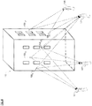
- FIG. 1A depicts building 100 having multi-view architectural lighting ("MVAL") system 106 in accordance with the illustrative embodiment of the present invention.
- Building 100 itself is of conventional design and includes at least one set of doors 102 and a plurality of windows 104. Front F, left side LS, and roof R of building 100 are visible in FIG. 1A .
- MVAL multi-view architectural lighting
- the MV lights (hereinafter collectively referenced “MV lights 108 ”) are sited at different locations on the exterior of building 100 in accordance with a layout developed by, for example, a lighting designer.
- MVAL system 106 also includes controller 110 and cable(s) 112 for supplying data for calibrating and/or operating the system, at least some of which is generated by the controller, and power to MV lights 108. For clarity, the connections between cable(s) 112 and MV lights 108 are not depicted.
- power-over Ethernet is used to send power and data to each MV light 108 i in MVAL system 106. This enables the use, in MVAL system 106, of standard networking gear and a single cable (carrying both power and data) to each MV light 108 i , In some other embodiments, power and data are sent over different cables and different data and/or power delivery schemes are used.
- each MV light 108 i is able to emit different light in a number of different directions.
- the light emitted in each such direction is referred to as a "beamlet.”
- each MV light 108 i is a source of a plurality of individually controllable beamlets of light, wherein the beamlets are emitted in a different direction than other of the beamlets emitted from the MV light and wherein the beamlets:
- Controller 110 provides several functions, including, without limitation:
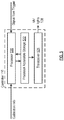
- Controller 110 includes processor 520, processor-accessible storage 522, and transceiver 524.
- Processor 520 is a general-purpose processor that is capable of, among other tasks, executing an operating system, executing device drivers, and executing specialized application software used in conjunction with the embodiments of the invention.
- Processor 520 is also capable of populating, updating, using, and managing data in processor-accessible data storage 522.
- processor 520 is a special-purpose processor. It will be clear to those skilled in the art how to make and use processor 520.
- Processor-accessible data storage 522 is non-volatile, non-transitory memory technology (e.g,, RAM, ROM, EPROM, EEPROM, hard drive(s), flash drive(s) or other solid state memory technology, CD-ROM, DVD, etc.) that stores, among any other information, data, device drivers (e.g ., for controlling MV lights 108, etc .), and specialized application software, which, when executed, enable processor 520 and MV lights 108 to perform as disclosed herein, It will be clear to those skilled in the art how to make and use processor-accessible data storage 522.
- Transceiver 524 enables one or two-way communications with input/locating devices and/or other devices and systems via any appropriate medium, including wireline and/or wireless, and via any appropriate protocol (e.g ., Bluetooth, Wi-Fi, cellular, optical, ultrasound, etc .).
- the term "transceiver” is meant to include any communications means and, as appropriate, various supporting equipment, such as communications ports, antennas, etc. It will be clear to those skilled in the art, after reading this specification, how to make and use transceiver 524.
- controller 110 includes a boot loader that wakes up and downloads the necessary software and data from one or more remote servers via a network into volatile memory of the controller. Those skilled in the art will know how to implement such other implementations of controller 110.
- FIG. 1A With continued reference to FIG. 1A , four viewers V1, V2, V3, and V4 are simultaneously observing building 100 at night. Viewers V1 and V2 have a view of front F of building 100, viewer V3 has a view of front F and left side LS of building 100, and viewer V4 has a view of left side LS of building 100. MVAL system 106 is activated.
- each of the four viewers sees rather different lighting content (in this case, different lighting patterns), even though building 100 is being viewed simultaneously by all of the viewers.
- viewer V1 sees lighting pattern AA
- viewer V2 sees lighting pattern BB
- viewer V3 sees lighting pattern CC on front F of the building and lighting pattern DD on left side LS of the building
- viewer V4 sees lighting pattern EE.
- the patterns AA through EE are enlarged for clarity in FIGs. 1B through 1E , respectively.
- FIG. 1B it appears to viewer V1 that only the MV lights along the perimeter of front F of the building are illuminated, thereby defining the inverted "u" arrangement of lighting pattern AA.
- Viewer V2 perceives only the pairs of MV lights 108 above and below the windows to be illuminated, defining lighting pattern BB as depicted in FIG. 1C .
- Lighting pattern CC shown in FIG. 1D , as seen by viewer V3 when looking at front F of building 100, is very different from what is seen by either viewer V1 or V2.
- the uppermost and lowermost rows of MV lights 108 appear to viewer V3 to be illuminated, as well as MV lights 108 contiguous therewith located directly above the top row of windows and below the bottom row of windows, as well as the central portion of the leftmost and rightmost column of MV lights.
- Viewer V3 sees lighting pattern DD on left side LS of building 100.
- Lighting pattern DD is similar to lighting pattern CC, but scaled for the smaller dimensions of the left side of the building relative to the front of building 100.
- Viewer V4 sees lighting pattern EE, depicted in FIG. 1E , which is different from the lighting patterns viewed by the other viewers.
- viewer V4 sees only the MV lights 108 sited along the left and right perimeter of left side LS of the building as being illuminated.
- the color of the light in one or more of the lighting patterns could be different from that of one or more of the other lighting patterns.
- a given lighting pattern need not be monochromatic.
- lighting patterns can be dynamic, alternatively turning "on” and "off,” or appearing to change in other ways. It is worth noting that, in order for an MV light to be visible from a given viewing location, there must be a beamlet from that light that illuminates that particular viewing location.
- the MV light The capability of MVAL system 106 to display, simultaneously, different lighting content to different viewers is a consequence of the aforementioned ability of each MV light 108 i to controllably emit beamlets of light in different directions.
- An embodiment of MV light 108 i identified as MV light 208 i , is depicted in FIG. 2 .
- MV light 208 i is projector-based and includes 256 conventional pixels 214 j arranged in a 16 x 16 array 215.
- the MV light can include less than or more than 256 conventional pixels.
- a current implementation includes about 500,000 conventional pixels and some next generation embodiments will include millions of pixels.
- MV light 208 i can be implemented using a projector, such as a "pico-projector;” and any suitable projection technology (e.g ., LCD, DLP, LCOS, etc .) can be used.
- Pico-projectors are commercially available from Texas Instruments, Inc. of Dallas, Texas and others.
- a pico-projector includes an LED light source; collection optics, which direct the light from the LED to an imager; an imager, typically a DMD (digital micromirror device) or an LCOS (liquid-crystal-on-silicon) device, which accepts digital-display signals to shutter the LED light and direct it to the projection optics; output or projection optics, which project the display image on the screen and also permit functions such as focusing of the screen image; and control electronics, including the LED drivers, interfacing circuits, and the video and graphics processor. See, e.g., http://www.embedded.com/print/4371210.
- off-the-shelf pico-projectors are modified, for example, to reduce brightness compared with conventional projection applications.
- FIG. 2 presents a greatly simplified representation of projector operation, focusing on the aspects that are germane to an understanding of the present invention.
- Light such as from light source 213, is directed toward pixel array 215 (e.g ., the DMD or LCOS device, etc.).
- pixel array 215 e.g ., the DMD or LCOS device, etc.
- light source 213 is depicted as being located behind pixel array 215, in some other embodiments, the light source is disposed in front of pixel array 215, as a function of the projector technology.
- the array of conventional pixels 214 j in combination with lens 218, defines a "multi-view pixel" capable of generating a plurality of beamlets, each with a unique emission direction. See , U.S. Pat. App. SN 15/002,014 ( US Pat Pub 2016/0212417 A1 ). Thus, MV light 208 i with its 256 conventional pixels is capable of generating 256 beamlets.
- the light impinging on such pixels is directed (via reflection or transmission) toward lens 218, which generates beamlet 216 j from the received light.
- lens 218, which generates beamlet 216 j from the received light For example, conventional pixels 214 84 and 214 94 .
- conventional pixel 214 84 directs the light it receives toward lens 218. That light propagates from pixel 214 84 in all directions. Lens 218 collects a sizable fraction of that light and collimates it into beamlet 216 84 .
- conventional pixel 214 94 when conventional pixel 214 94 is activated, it directs the light it receives toward lens 218.
- That light propagates from pixel 214 94 in all directions, a sizeable fraction of which is collected by lens 218 and collimated into beamlet 216 94 .
- the emission directions of respective beamlets 216 84 and 216 94 will differ from one another.
- pixel 214 84 passes blue light when activated, then a viewer whose eyes receive beamlet 216 84 will see a blue "dot.” If pixel 214 94 passes red light when activated, then a viewer whose eyes receive beamlet 216 94 will see a red “dot.”
- the size/appearance of the "dot" can vary in size and shape based on the operation of lens 218.
- MV light 208 i depicted in FIG. 2 is able to emit as many as 256 different beamlets.
- Each beamlet 216 j can be a different color and/or intensity from some or all of the other pixels of the same MV light and each will have a different emission direction.
- the beamlets can differ from one another in other properties of light (e.g., spectral composition, polarization, beamlet shape, beamlet profile, overlap with other beamlets, focus, spatial coherence, and temporal coherence).
- the emission direction of beamlet 216 j can be characterized by two angles, such as azimuth ⁇ and altitude ⁇ . It is notable that although beamlets are depicted in the accompanying figures as simple lines with an arrowhead indicating their direction of emission, they can have an angular extent and can be any shape. For this reason, characterizing the beamlet using the aforementioned two angles is necessarily an approximation. For example, and without limitation, beamlets might have a shape similar to the beam from a searchlight, but typically smaller. Furthermore, the conventional pixels that compose each MV light can be arranged in a circular pattern, a quadrilateral pattern, or any other convenient arrangement.
- the MV light are known in the art (such as when based on a pico-projector).
- the emission direction of each conventional pixel is determined and mapped to the environment of the MVAL system so that, in conjunction with the controller's ability to independently address each conventional pixel and control characteristics of the beamlet associated with each such pixel, different lighting content (e.g ., patterns, shows, information, etc .) can be simultaneously displayed (from the same MV lights) to different viewing zones.
- a further important feature of embodiments of the invention is that the MV lights of the MVAL system can be arranged by an installer in arbitrary physical configurations, yet still share, through the operation of the controller, a common understanding of the location of viewing zones so that desired lighting content is achieved with a single integrated system.
- This distinguishes the MVAL system for example, from multi-view displays disclosed by applicant ( see , e.g., U.S. Pat. Appl. SN 15/002,014 ).
- multi-view displays comprise a plurality of multi-view pixels, which are: typically constrained to a planar arrangement, point in the same direction, and are all visible from any viewing location.
- each MV light 108 j defines a single multi-view pixel.
- each multi-view pixel each MV light
- each multi-view pixel each MV light
- the multi-view pixels of an MVAL system need not constrained to a planar arrangement, do not necessarily point in the same direction, and often are not all visible from any viewing location.
- the user the lighting designer, etc.
- the manufacturer determines the arrangement of multi-view pixels with respect to one another.
- the MV lights are separated from one another by a distance that is greater than the resolving power of the human eye as viewed from intended viewing zones. As such, each MV light is distinctly resolved by a viewer.
- each multi-view pixel is typically located very close to one another (sub-millimeter spacing) so that individual multi-view pixels cannot be separately resolved.
- the limit of resolution of the human eye is typically considered to be in the range of about 1 to 2 arc minutes.
- the MV lights of an installed MVAL system will be separated by a minimum of about 1 arc minute, as viewed from the intended viewing zones.
- the multi-view pixels i.e ., each MV light
- MV light 108 i is projector based.
- MV light 108 j is not projector based; for example, each pixel is itself a light source, i.e ., a material that is able to glow, emitting light when electrically excited with an appropriate electrical excitation (e.g ., LED, OLED, etc.).
- These (conventional) pixels can be organized in a planar array. Light from these individually addressable pixels is collects by a lens. The lens collimates the light from a given selectively activated pixel to generate a beamlet.
- This arrangement defines a multi-view pixel capable of generating a plurality of beamlets each having a different emission direction as a function of the location of the pixel in array.
- a collection of individual lights LEDs, spotlights, etc.
- Each individual light generates a beamlet having a different emission direction than other lights in the grouping.
- MVAL system 106 depicted in FIG. 1A and viewers' V1 through V4 experience thereof as depicted in FIGs. 1B through 1F , is now discussed in further detail by examining the operation of several of MV lights 108 of the system.
- MV lights 108 11 ,108 85 ,108 105 , 108 147 ,108 156 depicted in FIG. 1A and again in FIG. 4 .
- the latter figure depicts, for the sake of clarity, a simplified view of building 100, MVAL system 106, the subject MV lights, and viewers V1 through V4.
- a ray tracing shown as a "dashed" line from an MV light indicates a beamlet emitted in the indicated direction.
- a ray tracing shown as a "dotted" line indicates that no beamlet (no light) is emitted in the indicated direction.
- FIG. 1C Viewer V2 who has a view of front F of building 100, sees lighting pattern BB depicted in FIG. 1C . Consequently, of the three MV lights 108 11 , 108 85 , 108 105 on front F of the building, MV lights 108 85 and 108 105 appear to be illuminated and MV light 108 11 appears dark. This means that the particular pixel(s) of MV lights 108 85 and 108 105 that generates a beamlet(s) that propagates in a direction that causes the beamlet(s) to reach the eyes of viewer V2 are activated. Conversely, the particular pixel(s) of MV lights 108 11 that generate a beamlet(s) that propagates in a direction that would otherwise cause it to reach the eyes of viewer V1 is not activated.
- Viewer V3 who has a view of front F and left side LS of building 100, sees respective lighting patterns CC and DD depicted in FIG. 1D . Consequently, of the three MV lights 108 11 , 108 85 , 108 105 on front F of the building, MV light 108 11 appears to be illuminated and MV lights 108 85 and 108 105 appear dark. And of the two MV lights 108 147 and 108 156 on left side LS of the building, both appear to be illuminated.
- the particular pixel(s) of MV lights 108 11 , 108 147 , and 108 156 that generate a beamlet(s) that propagates in a direction that causes the beamlet(s) to reach the eyes of viewer V3 are activated.
- the particular pixel(s) of MV lights 108 85 and 108 105 that generate a beamlet(s) that propagates in a direction that would otherwise cause it to reach the eyes of viewer V1 are not activated.
- Viewer V4 who has a view of left side LS of building 100, sees lighting pattern EEB depicted in FIG. 1E .
- MV light 108 147 appears to be illuminated while MV light 108 156 appears dark.
- the particular pixel(s) of MV light 108 156 that generates a beamlet(s) that propagates in a direction that would otherwise cause it to reach the eyes of viewer V4 is not activated.
- MVAL system 106 examined the operation of MVAL system 106 in the context of only five of its many lights. It will be understood that this process of illuminating (or not illuminating) pixel(s) of a MV light is performed for every MV light in the MVAL system. For example, from the perspective of viewer V1, only the MV lights along the perimeter of front F of building 100 are illuminated. Therefore, the pixel(s) in each MV light along the perimeter of the building that cause a beamlet to reach viewer V1 's eyes are illuminated. And for MV lights that are not located along the perimeter of the building, the pixel(s) in each of those lights that would otherwise cause a beamlet to reach viewer V1 's eyes are not illuminated.
- perimeter-located MV lights might or might not be illuminated as a function of: (1) the direction in which they emit a beamlet and (2) the particular lighting design.
- other pixels of those non-perimeter MV lights might be illuminated to generate other light patterns visible to viewers located in different viewing locations.
- MVAL system 106 For MVAL system 106 to display a particular lighting pattern to a viewer at a particular viewing location, specific MV lights 108 i of the MVAL system must emit light to that viewing location. For this to occur, elements (e.g ., controller 110, etc .) of MVAL system 106 must know, at a minimum, for each MV light 108 i in the system: (a) the emission direction of each beamlet originating from the multiple pixels 214 j that compose the MV light, and (b) which emission direction(s) illuminate which particular viewing zones.
- MVAL system 106 In embodiments in which MVAL system 106 is capable of generating light of more than one color, then MVAL system 106 must also have knowledge of the color of the beamlet generated by each pixel of each MV light. In some embodiments, calibration yields a table of relationships between locations in the viewing region and beamlets.
- Calibration of the MVAL system 106 is accomplished via any one of a variety of techniques.
- the emission direction of each the plural beamlets emitted from the plural pixels is determined by measurements obtained from a calibration device(s) situated in the region -the viewing region- in which viewers will view the lighting,
- Calibration techniques for a multi-view display are described in U.S. Pat. Application SN 15/002,014 ( U.S. Pat. Pub. 2016/0212417 A1 ), which is incorporated herein by reference.
- the calibration techniques described therein are generally suitable for use with the MVAL systems disclosed herein. It is within the capabilities of those skilled in the art, in light of the referenced disclosure and the present disclosure, to apply the calibration techniques described in S.N. 15/002,014 to the MVAL systems discussed herein.
- MVAL systems will often be required to work over large distances. For example, it is not uncommon to light skyscrapers so that they may be seen for many miles. In such scenarios, it is typically not practical to perform calibration in the manner referenced above (i.e ., moving a calibration device throughout the viewing region to calibrate all viewing locations. Rather, method 600, as depicted in FIG. 6 , can be used instead.
- MV lights 108 of an MVAL system are "pre-calibrated.”
- pre-calibrated means that the lights are calibrated prior to installation, such as during manufacture.
- This calibration involves determining the emission direction of each beamlet emitted from a given MV light with respect to a pointing direction the MV light. This concept is illustrated in FIG. 7 , wherein two beamlets 716 2 and 716 7 are sourced from respective pixels 714 2 and 714 7 of MV light 108 i . These beamlets each have an emission direction characterized by, for example, an azimuth and an altitude, as discussed in conjunction with FIG. 3 . It is notable that in FIG.
- the MVAL system is installed. Since light can be considered to travel in a straight line in air, the pre-calibration information is sufficient to characterize the emission directions of each of the plurality of beamlets emitted from each MV light with respect to the pointing direction of each such MV light.
- the pointing direction PD of each installed light must be determined so that the MVAL system can be registered to its environment. In some embodiments, this is accomplished using a calibration device, having, for example, a light emitter and a camera.
- Calibration device 522 can be positioned, for example, at two known locations relative to the known location of the light.
- One or more beamlets having known emission directions are emitted from each MV light 108 i and received by the camera of the calibration device at known locations in the viewing region. Since each beamlet can be associated with a unique pattern, the information captured by the camera, which is transmitted to controller 110, can uniquely identify the particular beamlet received. Due to the fixed relationship between the emission direction of each beamlet emitted from each MV light and the pointing direction of each such MV light, sufficient information is therefore available ( e.g ., to controller 110, etc .) to determine the pointing direction of each MV light 108 i .
- the MV lights are "registered" to a 3D model of the viewing region.
- a 3D model of the viewing region i.e ., the city in this scenario
- the location and pointing direction of each MV light, obtained at tasks 601 and 602 is registered to the 3D model. That is, each MV light is "oriented" in the 3D model.
- the location of the MV light in the 3D model is known, obtaining measurements at two locations is suffice to determine the pointing direction of the MV light. If it can be reasonably assumed that the camera is level along the "roll" axis, a measurement at only one location is required. If the position of the camera is not known (in the model), it can be determined by obtaining measurements at more than two locations.
- the "landing spots" for each beamlet from each MV light in the MVAL system can be estimated.
- "landing spot” is the estimated location, such as a viewing zone, in which each particular beamlet will "land;” that is, intersect a surface, such as a viewer's eyes. Consequently, the system has the information required to determine which beamlets from which MV lights are viewable from which particular neighborhoods. This information can be used to present different lighting patterns to different viewers located in different neighborhoods.
- each MV light 108 i includes an optical sight and a camera, or a mount in which those alignment devices are temporarily attached.
- the optical sight can be used to help properly point the camera and to perform later alignment tasks. Assuming the camera has a known viewing relationship to the MV light, that relationship can be used to find the landing spots for beamlets using a single picture from the camera.
- the registration procedure can be to take the images obtained by the camera on each MV light, indicate on each image where known locations appear on the images, and then find the corresponding beamlets from the pre-calibration data.
- FIG. 8A depicts an illustrative embodiment of user interface 830 for controlling MVAL system 106.
- a user can program MVAL system 106 to present a desired lighting effect to a particular viewing zone.
- the user interface includes a region 832 in which the viewing region for the MVAL system of interest is displayed.
- the representation of the viewing region can be actual camera footage, a graphical rendering, or any other approach for visually representing a particular viewing zone.
- Viewing zone 848 is movable (via a mouse, etc.) within the viewing region and can also be reshaped and/or re-sized to define and represent the shape and scaled size of a desired viewing zone.
- Lighting options for viewing zone 848 can be accessed by pressing "lighting" button 836. Successive presses of the lighting button enables a user to view all lighting patterns available for the selected viewing zone. The user selects a desired lighting pattern by, for example, "clicking" on it.
- FIG. 8B depicts selected lighting pattern 850 in region 832 of user interface 830. Once a particular lighting pattern is selected, "clock" button 844 is pressed. This provides access to a screen (presented in region 832 ) that enables a user to set a schedule for displaying the selected lighting pattern. In accordance with the schedule, controller 110 generates the selected light pattern by, in part, accessing the calibration table that relates beamlets to locations within the viewing region ( i.e ., viewing zones).
- user interface 830 also includes:
- a user interface suitable for use in conjunction with MVAL system 106 can be implemented in many ways other than what is described above. In light of the present disclosure, it is within the capabilities of those skilled in the art to design and implement a user interface for use in conjunction with MVAL system 106.
- Multi-View Architectural Lighting system can be used to entertain, inform, direct, or otherwise provide useful benefit.
- an MVAL system can target the effect to be visible only in the desired area. For example, inserting and turning an appropriate key in a lock might trigger the lighting effect to be visible in the area surrounding the lock.
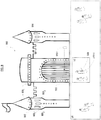
- FIG. 9 depicts an illustration of the foregoing "triggered" MVAL experience wherein castle 960 includes an MVAL system having controller 910 and a plurality of MV lights 908. Normally, the only lights on castle 960 that appear lit are MV lights 908 1 , 908 2 , and 908 3 , which are disposed directly beneath windows 964 on turrets 962. These MV lights appear to be lit to any amusement park patron regardless of their location in viewing region VR.
- the goal of the castle amusement is to trigger the lighting display by waving or pointing "magic wand" 968.
- Sensor 966 which can be, for example, a camera and image recognition software, light sensor, etc ., as appropriate, senses movement or a position of the "magic wand” or a signal emitted therefrom. Once sensed, a signal is generated and/or transmitted by sensor 966 to controller 910, which causes all MV lights 908 ( i.e. , those on turrets 962, those surrounding the drawbridge, etc. ), which are normally "off,” to illuminate for a brief period of time ( e.g ., 10 seconds, etc .).
- amusement park patron AAP-1 must be located in viewing zone VZ when she waves or aims magic wand 968. Consequently, if she triggers the sensor, patron AAP-1 and any companions standing within viewing zone VZ will experience the lighting display. Amusement park patrons standing outside of viewing zone VZ will be unaware of the lighting display experience by those in viewing zone VZ; they will continue to perceive, as illuminated, only the three lights under each window.
- the MVAL system may be installed on any structure and the triggering device may take any of a variety of forms as is suitable for the particular context (the nature of the amusement).
- the triggering device is a fanciful device, developed exclusively for the amusement and non-functional outside of that context. Examples of a fanciful device include, without limitation, the previously mentioned "magic wand” or a "ray gun” weapon.
- almost any detectable action can serve as a trigger. For example, emission and detection of light, pulling a lever, pressing a button, turning a key, opening a door, crossing a threshold, etc .).
- a patron rather than having a single trigger, a patron must complete a series of tasks (e.g ., respond to questions, follow clues, physical feats, etc .) to trigger the lighting effect, In some embodiments, the triggered light show occurs at a later time and/or in a different location.
- a series of tasks e.g ., respond to questions, follow clues, physical feats, etc .
- the triggered light show occurs at a later time and/or in a different location.
- the MVAL system includes a tracking-system sensor that tracks the location of a portable device (e.g ., magic wand 968, etc .) that is used by a patron to attempt to trigger the lighting display.
- a portable device e.g ., magic wand 968, etc .
- magic wand can be tracked by a camera, which transmits acquired images to image-recognition software.
- the wand broadcasts a beacon that is tracked by the MVAL system.
- a tracking system is used to target the lighting effect to a particular patron. Tracking systems for tracking a patron include, without limitation, facial recognition software, blob tracking, and/or tracking of cellphones.
- an MVAL system is configured to interact with devices, such as a device owned by a third-party viewer, such as a patron/visitor.
- a smartphone application enables the third-party viewer, via his smartphone, to select custom lighting content (e.g ., a lighting pattern, a lighting show, a message, etc .) for viewing.
- lighting content is a prize for completing an in-game task.
- the MVAL system needs to know what lighting content to show to which viewing locations. More generally, when certain actions are taken with an electronic device (e.g ., smartphone, tablet, computer, etc. ), the device triggers the MVAL system to display lighting content in the region of the person that triggers the event.
- the location of the device can be determined, for example and without limitation, via RF locating systems, auditory locating systems, and/or visual locating systems.
- MVAL system provide complex and dynamic light shows in pedestrian areas, while simultaneously showing static lighting from a street ( i.e. , driver's) view.
- FIG. 10 depicts an example of this usage.
- Building 1072 has MVAL system including controller 1010 and a plurality of MV lights 1008 i .
- the MVAL system is operated such that viewing zones 1074-1, 1074-2, 1074-3, and 1074-4, which are pedestrian areas, see dynamic lighting content on building 1072.
- a pedestrian in viewing zone 1074-2 sees all lights 1008 flashing different colors.
- Pedestrians in the other viewing zones 1074-1, 1074-3, and 1074-4 can see other dynamic lighting patterns (or the same pattern as seen in viewing zone 1074-2 ).
- drivers in cars 1078 which are in viewing zones 1076, see a rather limited, non-distracting lighting display.
- the driver of vehicle 1078-1 sees lighting pattern GG, wherein only four lights are lit, continuously, one at each corner of the front face of building 1072.
- the roof of the building can exhibit lighting displays to be viewed from passing aircraft.
- different lighting presentations can simultaneously be shown to different aircraft. This can be accomplished, for example, using real-time flight data.
- plane 1182 arriving from France can see, on roof R of building 1180, lighting display HH that simulates the flag of France, with its "b" blue, "w” white, and "r” red color fields.
- passengers on plane 1184 arriving from Japan see lighting display II that simulates the Japanese flag, having "r" red circle in a white field.
- the two lighting presentations are simultaneously presented and passengers on plane 1182 will see only the French flag and passengers on plane 1184 will see only the Japanese flag.
- the individual MV lights of the MVAL system can be precalibrated and pointing directions can be determined with a very small number of measurements. These can be done by briefly placing a calibration device, as previously disclosed, at known positions in front of the MV lights.
- an MVAL system is employed to illuminate the proper airport runaway for each approaching plane. Since each plane is at a different location in the sky, runaway illumination will be visible only to the aircraft for which it is intended. Although each plane's location is constantly changing, it is readily tracked and updated with the airport's tracking systems.
- Projection mapping is becoming an increasingly popular lighting effect.
- video mapping and “spatial augmented reality”
- projection mapping uses a projection technology to turn objects, often irregularly shaped, into a display surface for video projection. These objects are commonly buildings or theatrical stages.
- a two- or three-dimensional object is spatially mapped on the virtual program that mimics the real environment it is to be projected on.
- the software interacts with a projector to fit any desired image onto the surface of the object. This technique enables a lighting designer, artist, etc., to add extra dimensions, optical illusions, and notions of movement onto what is a static object. By projecting directly onto a building, its appearance can be animated.
- bricks might be made to appear as if moving in and out of the building face. Such an effect is implemented by projecting the appearance of the brick in different positions.
- the projection must presume a certain viewing perspective and it is only when viewed from the presumed perspective that the picture of the extended brick appears to be correct. When viewed from other viewing locations, the perspective will appear wrong.
- an MVAL system is used for projection mapping.
- the MVAL system overcomes the single-viewing-location problem that has until now plagued 3D projection mapping technologies because the MVAL system enables independent control over what is seen from different viewing locations.
- an array of MV lights is used to outline the shape of the extended section as it would appear from different viewing locations.
- two viewers at two different positions observing an MVAL system both see a rectangular lighting pattern.
- one of the viewers perceives the rectangular illuminated lights moving "in” from her perspective, while simultaneously, the other of the viewers perceives them moving in from his perspective.
- the lighting pattern may be different to accommodate the two viewpoints, even though the resulting perception is similar.
- an MVAL system is used in conjunction with moving or mobile structures such as, without limitation, trucks, buses, parade floats, ships, and/or blimps. Motion is relative, and an MVAL system moving relative to a viewer can be treated as equivalent to a viewer moving relative to an MVAL system.
- a lighting show For designers of standard animated light shows on moving structures, the lighting show must be designed with the expectation that the show may come into view at any point during the animation.
- a lighting show can be designed to proceed, such that as it passes a succession of viewing locations, the viewers located at the various viewing locations can see the light show proceed in the correct order from beginning to end.
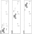
- MVAL system 1288 comprising a plurality of MV lights 1208 i and a controller (not depicted) is coupled to a moving vehicle 1286.
- the MVAL system is moving past three spatially separated stationary viewers V-A through V-C.
- FIG. 12A depicts the MVAL system/vehicle at first time
- FIG. 12B depicts the MVAL system/vehicle at a second time when it has moved toward viewer V-B
- FIG. 12C depicts the MVAL system/vehicle at a third time when it has moved toward viewer V-C.
- MVAL system 1288 is near to viewer V-A in a first viewing zone. Consequently, MV lights 1208 are controlled so that beginning light show content is directed toward viewer V-A while no light show content is viewable by viewers V-B and V-C.
- MVAL system 1288 has moved towards viewer V- B in a second viewing zone. The MVAL system causes the MV lights 1208 to direct middle light show content to viewer V-A and beginning light show content to viewer V-B.
- MVAL system 1288 has now moved towards viewer V-C in a third viewing zone. The MVAL system causes end light show content to be directed towards viewer V-A, middle light show content is directed towards viewer V-B, and beginning light show content is directed towards viewer V-C. Each viewer will therefore see the lighting show in the proper sequence as MVAL system 1288 proceeds.
- the MVAL system is triggered to direct lighting content to the viewing zones as a function of timing. That is, the controller can determine where, based on the speed of travel, vehicle 1286 is at any moment in time and causes the proper lighting content to display as a function of the determined position.
- a sensor that senses the location of MVAL system 1288 is used to trigger the display of appropriate lighting content to the various viewing zones. Any of a variety of sensor arrangements can be used, including optical, RF, etc, It is notable that in some embodiments, appropriate lighting content is no lighting content.
- an MVAL system can be used to guide a person to an intended destination.
- a person requests guidance to a desired location at an appropriate interface.
- the MV lights of the MVAL system can light a path to the desired location, wherein the path is visible only to the requestor (by tracking the requestor). Based on their previously described functionality, the same MV lights can, at the same time, direct other people to different locations.
- the request for directions is placed via a suitable interface, such as is available through a nearby kiosk, an App downloaded to the person's smart phone, or an attendant that takes the person's request and inputs it into the MVAL system, etc.
- a tracking/sensing system acquires the information needed to track the requestor. For example, in some embodiments, the tracking/sensing system associates the person's smart phone with the request, In some other embodiments, the system acquires an image of the person and uses facial recognition software for tracking, in yet further embodiments, the person is given a transmitter. In some embodiments, each transmitter is identified with a particular destination and is pre-configured to transmit a code to the system that indicates the particular destination.
- the transmitter transmits to the system and the system illuminates the appropriate MV lights to guide the holder of the transmitter to the pre-assigned destination.
- the transmitter is assigned a destination at the time it is acquired by the person.
- FIG. 13A depicts an embodiment wherein MVAL system 1392 is configured to help multiple people simultaneously navigate to different locations through portion 1390 of a building.
- MVAL system 1392 includes a plurality of MV lights 1308 i disposed in the walls of the corridors, a controller (not depicted), and a sensing/tracking system (not depicted) as described above.
- the MVAL system is configured to simultaneously illuminate different paths for different persons V-A, V-B, V-C, V-D, and V-E (based on their different viewing angles with respect to the MV lights) wishing to reach respective destinations A, B, C, D, and E.
- FIG. 13B through FIG. 13F depict the illumination perceived by respective viewers V-A, V-B, V-C, V-D, and V-E. Illuminated lights are appear to be "black" in the Figures.
- architectural lighting refers generally to lighting on the outside of buildings, bridges, and other structures that is meant to do more than simply “illuminate.” That is, such lighting serves both functional and aesthetic purposes.
- the term “architectural lighting” extends to lighting that is installed on the exterior of a vehicle (e.g ., car, train, etc .) wherein the lighting is not for the purpose of illuminating the road (headlights) or making the vehicle noticeable to others (tail lights), but rather is intended to provide content, either in the form of a lighting show or information.
- the term architectural lighting applies to indoor lighting that is intended for a purpose other than simple illumination.
- a "beamlet” is defined as an elemental entity of light emitted by an MV light.
- An MV light emits plural beamlets, each of which having an emission direction different from that of other beamlets emitted from the MV light. At least some of the beamlets are controllable independently of other beamlets emitted by the MV light.
- the light intensity and/or color of an individual beamlet is controllable independently of the intensity and/or color of the light of other beamlets emitted from the same MV light.
- an MV light can controlled to emit light in certain directions but not others; or to independently adjust the brightness or color of light emitted in different directions.
- beamlet light can also be adjusted independently for different directions of emission.
- Other parameters of beamlet light might also be controlled, such other parameters comprise, for example, spectral composition, polarization, beamlet shape, beamlet profile, overlap with other beamlets, focus, spatial coherence, temporal coherence, etc., to name just a few. It is notable that the word "beamlet” does not appear in standard dictionaries and has no accepted meaning in the industry.
- a “fanciful device” is a device that does not exist or function apart from its use in conjunction with an MVAL system.
- One example is a "magic wand" that a viewer of the lighting system aims or waves to trigger a response from an MVAL system.
- a “lighting pattern” or “lighting display” refers to a pattern/arrangement of light perceived by a viewer.
- the pattern is determined by which MV lights of an MVAL system appear to the viewer to be lit, as a function of the viewer's viewing location with respect to the MV lights, and is further determined by the intensity, color, and/or other characteristics of the light emitted by the MV lights to the viewer's viewing location.
- Lighting content refers to one or more lighting patterns, lighting shows, or information (in the form of words, numbers, symbols, etc.) provided via MV lights.
- a "lighting plan” refers to the locations on a structure, etc., where MV lights are intended to be placed so that, when the MVAL system is active, various lighting displays can be presented to various viewing zones.
- a "multi-view pixel” is a more flexible version of the type of pixel used in conventional (non-multi-view displays).
- the light from a conventional pixel propagates in all directions, such that all viewers perceive the pixels essentially the same way, regardless of viewer position
- a multi-view pixel can control the spatial distribution (emission direction) of light.
- a multi-view pixel can be commanded, for example, to emit light in certain directions but not others.
- it can be commanded to independently adjust the brightness of light emitted in different directions.
- Other parameters of emitted light can also be adjusted independently for different directions of emission.
- a "third party viewer” is a viewer of an MVAL system who does not own/lease the structure on which the MVAL system is installed, is not involved in the design or maintenance of the MVAL system, is not an owner/operator of a facility in which the MVAL system is used ( e.g ., a theme park, etc .), and is not involved in the daily operation of the MVAL (other than, in some embodiments, to have a limited amount of control over the operation of the MVAL system via an App, etc ., that is provided for the express purpose of enabling a third party viewer to briefly trigger a lighting display or have a limited amount of control over the lighting content presented during such brief system control).
- a “viewing region" of an MVAL system refers to the range of possible positions/locations from which viewers of the lighting system can experience the MVAL system functionality.
- the MV lights of the MVAL system can emit beamlets in a range of possible directions. A viewer must be within that range in order to see at least one beamlet. For a viewer to see a full lighting pattern ( e.g ., as presented on a building), the viewer must be within the beamlet range of all MV lights responsible for creating that pattern.
- the viewing region is the collection of all positions where this requirement is met.
- a “viewing zone” is typically a subset of a viewing region; that is, there are typically plural viewing zones in a viewing region. Based on a different viewing angle(s) in different viewing zones, different lighting content can simultaneously be presented to different viewing zones.
Landscapes
- Engineering & Computer Science (AREA)
- Theoretical Computer Science (AREA)
- Marketing (AREA)
- Physics & Mathematics (AREA)
- General Physics & Mathematics (AREA)
- Accounting & Taxation (AREA)
- Business, Economics & Management (AREA)
- Architecture (AREA)
- Civil Engineering (AREA)
- Structural Engineering (AREA)
- General Engineering & Computer Science (AREA)
- Circuit Arrangement For Electric Light Sources In General (AREA)
- Illuminated Signs And Luminous Advertising (AREA)
- Controls And Circuits For Display Device (AREA)
Claims (15)
- Système d'éclairage architectural multivue (106) comprenant :une pluralité de lampes multivues (108), dans lequel :(A) chaque lampe multivue (108) est constituée d'un unique pixel multivue, le pixel multivue comportant une lentille (218) et une matrice (215) de pixels classiques (214), les pixels classiques (214) ayant différentes orientations angulaires par rapport à la lentille (218) de telle sorte que le pixel multivue soit capable de générer une pluralité de faisceaux élémentaires (216), chacun d'eux ayant une direction d'émission différente de celle d'autres des faisceaux élémentaires (216) de la pluralité ;(B) un placement de chaque lampe multivue (108) par rapport à un placement de chaque autre lampe multivue (108) n'est pas limité à un plan ;le système d'éclairage architectural multivue (106) comprenant en outre un contrôleur (110) pour commander la pluralité de lampes multivues (108) de telle sorte qu'au moins certains faisceaux élémentaires (216) de la pluralité de ceux-ci soient sélectivement générés et émis de manière que, simultanément et à partir de la même pluralité de lampes multivues (108) :(i) un premier motif d'éclairage généré par au moins certains des faisceaux élémentaires sélectivement générés (216) soit perceptible au niveau d'une première zone d'observation d'une région d'observation ;(ii) soit :(a) un deuxième motif d'éclairage généré par au moins certains autres des faisceaux élémentaires sélectivement générés (216) soit perceptible au niveau d'une deuxième zone d'observation de la région d'observation ; soit(b) aucun motif d'éclairage ne soit perceptible au niveau d'une deuxième zone d'observation de la région d'observation parce que des faisceaux élémentaires (216) ayant une direction d'émission de nature à amener un motif d'éclairage à être perceptible dans la deuxième zone d'observation ne sont pas générés ;(iii) la première zone d'observation et la deuxième zone d'observation aient des angles d'observation différents l'un de l'autre par rapport aux lampes multivues ; et(iv) le premier motif d'éclairage ne soit pas perceptible au niveau de la deuxième zone d'observation et, dans le cas de (ii) (a), le deuxième motif d'éclairage ne soit pas perceptible au niveau de la première zone d'observation.
- Système d'éclairage (106) selon la revendication 1 et comprenant en outre un dispositif de déclenchement, dans lequel le dispositif de déclenchement, lorsqu'il est déclenché, amène le système d'éclairage (106) à présenter le premier motif d'éclairage.
- Système d'éclairage (106) selon la revendication 2, dans lequel le contrôleur (110) est configurable pour retarder la présentation du premier motif d'éclairage, après déclenchement, pendant une période de temps.
- Système d'éclairage (106) selon les revendications 2 ou 3 et comprenant en outre un système de suivi, dans lequel le système de suivi est configuré pour suivre un emplacement du dispositif de déclenchement et dans lequel l'emplacement du dispositif de déclenchement définit la première zone d'observation.
- Système d'éclairage (106) selon l'une quelconque des revendications 2 à 4, dans lequel le dispositif de déclenchement est un dispositif qui n'a pas d'autre fonction que d'interagir avec le système d'éclairage.
- Système d'éclairage (106) selon l'une quelconque des revendications précédentes et comprenant en outre une table, accessible au contrôleur et stockée dans un dispositif de stockage accessible par processeur, qui liste la direction d'émission de chaque faisceau élémentaire (216) à partir de chaque lampe multivue (MV) (108) par rapport à la première zone d'observation et à la deuxième zone d'observation.
- Système d'éclairage (106) selon l'une quelconque des revendications 1 à 5 et comprenant en outre des données d'étalonnage accessibles au contrôleur (110) et stockées dans un dispositif de stockage accessible par processeur, dans lequel les données d'étalonnage permettent le calcul de la direction d'émission de chaque faisceau élémentaire (216) à partir de chaque lampe multivue (MV) (108) par rapport à la première zone d'observation et à la deuxième zone d'observation.
- Système d'éclairage (106) selon l'une quelconque des revendications précédentes et comprenant en outre une interface utilisateur (830) pour sélectionner le premier motif d'éclairage et le deuxième motif d'éclairage parmi une pluralité de motifs d'éclairage qui sont présentables par le système d'éclairage.
- Système d'éclairage (106) selon l'une quelconque des revendications précédentes, le système d'éclairage (106) comprenant un système de détection configuré pour déterminer si d'éventuels observateurs sont présents dans la première zone d'observation, le système d'éclairage étant configuré pour ne pas présenter le premier motif d'éclairage vers la première zone d'observation lorsqu'aucun observateur n'est présent dans la première zone d'observation.
- Système d'éclairage (106) selon l'une quelconque des revendications précédentes, le système d'éclairage (106) étant installé sur une structure sélectionnée dans un groupe constitué d'un bâtiment, d'une attraction dans un parc à thème, d'une enseigne, d'une scène théâtrale et d'un véhicule.
- Procédé d'utilisation d'un système d'éclairage architectural multivue, le procédé comprenant :le positionnement d'une pluralité de lampes multivues (108) à des emplacements arbitraires dans l'espace 3D l'une par rapport à l'autre en fonction d'une structure sur laquelle les lampes multivues (108) sont installées et selon un plan d'éclairage, chaque lampe multivue (108) étant constituée d'un unique pixel multivue, le pixel multivue comportant une lentille (218) et une matrice (215) de pixels classiques (214), les pixels classiques (214) ayant différentes orientations angulaires par rapport à la lentille (218) de telle sorte que le pixel multivue soit capable de générer une pluralité de faisceaux élémentaires (216), chacun d'eux ayant une direction d'émission différente de celle d'autres des faisceaux élémentaires (216) de la pluralité ; etla génération et l'émission sélectives, simultanément, de faisceaux élémentaires (216) à partir d'au moins certaines des lampes multivues (108), de manière que :(i) un premier motif d'éclairage généré par au moins certains des faisceaux élémentaires sélectivement générés (216) soit perceptible au niveau d'une première zone d'observation d'une région d'observation ;(ii) soit :(a) un deuxième motif d'éclairage généré par au moins certains autres des faisceaux élémentaires sélectivement générés (216) soit perceptible au niveau d'une deuxième zone d'observation de la région d'observation ; soit(b) aucun motif d'éclairage ne soit perceptible au niveau d'une deuxième zone d'observation de la région d'observation parce que des faisceaux élémentaires (216) ayant une direction d'émission de nature à amener un motif d'éclairage à être perceptible dans la deuxième zone d'observation ne sont pas générés ;(iii) le premier motif d'éclairage et le deuxième motif d'éclairage soient générés par les mêmes lampes multivues (108) ;(iv) la première zone d'observation et la deuxième zone d'observation aient des angles d'observation différents l'un de l'autre par rapport aux lampes multivues ; et(v) le premier motif d'éclairage ne soit pas perceptible au niveau de la deuxième zone d'observation et, dans le cas de (ii) (a), le deuxième motif d'éclairage ne soit pas perceptible au niveau de la première zone d'observation.
- Procédé selon la revendication 11 et comprenant en outre le déclenchement d'un dispositif de déclenchement pour amener lesdites certaines lampes multivues à présenter le premier motif d'éclairage.
- Procédé selon la revendication 12 et comprenant en outre la présentation du premier motif d'éclairage au niveau d'une troisième zone d'observation lors du déclenchement.
- Procédé selon les revendications 12 ou 13, dans lequel une portion du dispositif de déclenchement est mobile, et comprenant en outre :le suivi d'un emplacement de la portion qui est mobile, etla désignation de l'emplacement de la portion qui est mobile comme étant au moins une partie de la première zone d'observation.
- Procédé selon l'une quelconque des revendications 11 à 14, comprenant en outre :la réception d'un signal provenant d'un dispositif électronique d'un observateur tiers, etle fait d'amener lesdites certaines lampes multivues à présenter du contenu d'éclairage, sur la base du signal reçu, vers un emplacement de l'observateur tiers.
Applications Claiming Priority (2)
| Application Number | Priority Date | Filing Date | Title |
|---|---|---|---|
| US201562174476P | 2015-06-11 | 2015-06-11 | |
| PCT/US2016/037185 WO2016201412A1 (fr) | 2015-06-11 | 2016-06-13 | Système d'éclairage architectural à vues multiples |
Publications (2)
| Publication Number | Publication Date |
|---|---|
| EP3308607A1 EP3308607A1 (fr) | 2018-04-18 |
| EP3308607B1 true EP3308607B1 (fr) | 2021-08-04 |
Family
ID=56204015
Family Applications (1)
| Application Number | Title | Priority Date | Filing Date |
|---|---|---|---|
| EP16732136.3A Active EP3308607B1 (fr) | 2015-06-11 | 2016-06-13 | Système d'éclairage architectural à vues multiples |
Country Status (8)
| Country | Link |
|---|---|
| US (1) | US9743500B2 (fr) |
| EP (1) | EP3308607B1 (fr) |
| JP (1) | JP6367499B1 (fr) |
| KR (1) | KR101956810B1 (fr) |
| CN (1) | CN107926095B (fr) |
| CA (1) | CA3026618C (fr) |
| ES (1) | ES2895097T3 (fr) |
| WO (1) | WO2016201412A1 (fr) |
Families Citing this family (19)
| Publication number | Priority date | Publication date | Assignee | Title |
|---|---|---|---|---|
| USD800758S1 (en) * | 2014-09-23 | 2017-10-24 | Seasonal Specialties, Llc | Computer display screen with graphical user interface for lighting |
| US10275948B2 (en) * | 2014-12-02 | 2019-04-30 | Operr Technologies, Inc. | Method and system for refilling a parking meter |
| US10701349B2 (en) | 2015-01-20 | 2020-06-30 | Misapplied Sciences, Inc. | Method for calibrating a multi-view display |
| US11099798B2 (en) | 2015-01-20 | 2021-08-24 | Misapplied Sciences, Inc. | Differentiated content delivery system and method therefor |
| US10955924B2 (en) | 2015-01-29 | 2021-03-23 | Misapplied Sciences, Inc. | Individually interactive multi-view display system and methods therefor |
| US10928914B2 (en) | 2015-01-29 | 2021-02-23 | Misapplied Sciences, Inc. | Individually interactive multi-view display system for non-stationary viewing locations and methods therefor |
| US10264247B2 (en) | 2015-02-03 | 2019-04-16 | Misapplied Sciences, Inc. | Multi-view displays |
| WO2016141248A1 (fr) | 2015-03-03 | 2016-09-09 | Misapplied Sciences, Inc. | Système et procédé pour afficher un contenu dépendant de l'emplacement |
| US10362301B2 (en) | 2015-03-05 | 2019-07-23 | Misapplied Sciences, Inc. | Designing content for multi-view display |
| US9715827B2 (en) | 2015-04-01 | 2017-07-25 | Misapplied Sciences, Inc. | Multi-view traffic signage |
| US9792712B2 (en) | 2015-06-16 | 2017-10-17 | Misapplied Sciences, Inc. | Computational pipeline and architecture for multi-view displays |
| US10602131B2 (en) | 2016-10-20 | 2020-03-24 | Misapplied Sciences, Inc. | System and methods for wayfinding and navigation via multi-view displays, signage, and lights |
| US10269279B2 (en) | 2017-03-24 | 2019-04-23 | Misapplied Sciences, Inc. | Display system and method for delivering multi-view content |
| US10427045B2 (en) | 2017-07-12 | 2019-10-01 | Misapplied Sciences, Inc. | Multi-view (MV) display systems and methods for quest experiences, challenges, scavenger hunts, treasure hunts and alternate reality games |
| US10565616B2 (en) | 2017-07-13 | 2020-02-18 | Misapplied Sciences, Inc. | Multi-view advertising system and method |
| US10404974B2 (en) | 2017-07-21 | 2019-09-03 | Misapplied Sciences, Inc. | Personalized audio-visual systems |
| US10778962B2 (en) | 2017-11-10 | 2020-09-15 | Misapplied Sciences, Inc. | Precision multi-view display |
| US12051343B2 (en) | 2020-02-18 | 2024-07-30 | Evolution Optiks Limited | Multiview system, method and display for rendering multiview content, and viewer localisation system, method and device therefor |
| CN111692539A (zh) * | 2020-05-11 | 2020-09-22 | 弗曦照明设计(北京)有限公司 | 一种多维度发光led媒体立面线性灯 |
Family Cites Families (49)
| Publication number | Priority date | Publication date | Assignee | Title |
|---|---|---|---|---|
| JPH06260005A (ja) * | 1993-03-04 | 1994-09-16 | Kansei Corp | スポットライト照射方向制御装置 |
| JP2846856B2 (ja) | 1996-07-19 | 1999-01-13 | 三洋電機株式会社 | 立体映像表示装置 |
| AUPP496198A0 (en) | 1998-07-31 | 1998-08-20 | Resmed Limited | Switches with graphical display |
| WO2002024470A1 (fr) * | 2000-09-25 | 2002-03-28 | The Singapore Mint | Surface a images multiples |
| JP2002208492A (ja) * | 2001-01-11 | 2002-07-26 | Almex Inc | サーチライトを使用した夜間照明システム |
| US20030115096A1 (en) | 2001-12-17 | 2003-06-19 | Reynolds Randy B. | Computer-controlled, remotely programmed at-shelf advertising system |
| WO2003058979A2 (fr) | 2002-01-04 | 2003-07-17 | Neurok Llc | Projection d'images tridimensionnelles au moyen d'ecrans retroreflechissants |
| GB0322681D0 (en) * | 2003-09-27 | 2003-10-29 | Koninkl Philips Electronics Nv | Multi-view display |
| US7369100B2 (en) | 2004-03-04 | 2008-05-06 | Eastman Kodak Company | Display system and method with multi-person presentation function |
| US7602395B1 (en) | 2005-04-22 | 2009-10-13 | Nvidia Corporation | Programming multiple chips from a command buffer for stereo image generation |
| JP2009540381A (ja) * | 2006-06-16 | 2009-11-19 | コーニンクレッカ フィリップス エレクトロニクス エヌ ヴィ | マルチビュー表示装置 |
| JP5313153B2 (ja) * | 2006-11-17 | 2013-10-09 | コーニンクレッカ フィリップス エヌ ヴェ | 照明制御のための光ワンド |
| IL183173A (en) | 2007-05-14 | 2013-11-28 | David Eduard Sitbon | An alert system located in the aisle to indicate a safety issue |
| WO2009013744A2 (fr) | 2007-07-23 | 2009-01-29 | Humaneyes Technologies Ltd. | Dddispositifs d'affichage à vues multiples et leurs procédés de fabrication |
| US8228196B1 (en) | 2008-07-25 | 2012-07-24 | Sprint Communications Company L.P. | Displaying advertisements based on electronic tags |
| TWI399719B (zh) * | 2008-08-07 | 2013-06-21 | Innolux Corp | 顯示裝置與其顯示方法 |
| KR101290013B1 (ko) * | 2008-10-07 | 2013-07-30 | 엘지디스플레이 주식회사 | 다중 뷰 영상표시장치 |
| US8075138B2 (en) | 2009-02-23 | 2011-12-13 | Third Dimension Ip Llc | System and methods for angular slice true 3-D display |
| US20110242298A1 (en) * | 2009-08-21 | 2011-10-06 | Microsoft Corporation | Private video presentation |
| US8854531B2 (en) | 2009-12-31 | 2014-10-07 | Broadcom Corporation | Multiple remote controllers that each simultaneously controls a different visual presentation of a 2D/3D display |
| US8941312B2 (en) * | 2010-01-19 | 2015-01-27 | Ncp Corporation | Apparatus and method for controlling LED light strings |
| US8687051B2 (en) | 2010-03-03 | 2014-04-01 | Fraunhofer-Gesellschaft Zur Foerderung Der Angewandten Forschung E.V. | Screen and method for representing picture information |
| EP2395759B1 (fr) | 2010-06-11 | 2015-03-04 | Sony Ericsson Mobile Communications AB | Dispositif d'affichage autostereoscopique et procédé de fonctionnement d'un dispositif d'affichage autospectroscopique |
| US8624960B2 (en) | 2010-07-30 | 2014-01-07 | Silicon Image, Inc. | Multi-view display system |
| JP5302285B2 (ja) | 2010-10-28 | 2013-10-02 | シャープ株式会社 | 立体映像出力装置、立体映像出力方法、立体映像出力プログラムおよびコンピュータ読み取り可能な記録媒体、ならびに、立体映像表示装置 |
| CN103534744A (zh) * | 2011-02-25 | 2014-01-22 | 特里利特技术有限公司 | 具有移动元件的照明装置 |
| US20120218253A1 (en) | 2011-02-28 | 2012-08-30 | Microsoft Corporation | Adjusting 3d effects for wearable viewing devices |
| US20130093752A1 (en) | 2011-10-13 | 2013-04-18 | Sharp Laboratories Of America, Inc. | Viewer reactive auto stereoscopic display |
| US9080279B2 (en) | 2011-10-24 | 2015-07-14 | Lg Electronics Inc. | Washing machine to produce three-dimensional motion |
| WO2013064971A2 (fr) * | 2011-11-02 | 2013-05-10 | Koninklijke Philips Electronics N.V. | Dispositif d'éclairage pour visions multiples, ensemble et luminaire |
| WO2013144773A2 (fr) | 2012-03-27 | 2013-10-03 | Koninklijke Philips N.V. | Affichage 3d pour plusieurs spectateurs |
| WO2013183108A1 (fr) | 2012-06-04 | 2013-12-12 | 株式会社Pfu | Dispositif, procédé et programme de traitement d'informations |
| KR20140007703A (ko) | 2012-07-10 | 2014-01-20 | 삼성전자주식회사 | 영상 디스플레이 장치 및 메뉴 디스플레이 방법 |
| KR101534901B1 (ko) * | 2012-09-04 | 2015-07-24 | 엘지이노텍 주식회사 | 조명 제어장치 및 방법 |
| US9989206B2 (en) * | 2013-03-11 | 2018-06-05 | Inception Innovations, Llc | Architectural lighting methods and apparatus |
| AU2014289922B2 (en) | 2013-07-11 | 2017-08-31 | Dejero Labs Inc. | Systems and methods for transmission of data streams |
| US20150042771A1 (en) | 2013-08-07 | 2015-02-12 | United Video Properties, Inc. | Methods and systems for presenting supplemental content in media assets |
| KR102220910B1 (ko) | 2014-01-10 | 2021-02-25 | 엘지전자 주식회사 | 가전제품 및 가전제품 제어방법 |
| US9706622B2 (en) * | 2014-05-16 | 2017-07-11 | Musco Corporation | Sports lighting to increase contrast of an aerial sports object relative to background |
| US9704392B2 (en) | 2014-12-02 | 2017-07-11 | Operr Technologies, Inc. | Method and system for legal parking |
| US11099798B2 (en) | 2015-01-20 | 2021-08-24 | Misapplied Sciences, Inc. | Differentiated content delivery system and method therefor |
| US10701349B2 (en) | 2015-01-20 | 2020-06-30 | Misapplied Sciences, Inc. | Method for calibrating a multi-view display |
| US10955924B2 (en) | 2015-01-29 | 2021-03-23 | Misapplied Sciences, Inc. | Individually interactive multi-view display system and methods therefor |
| US10264247B2 (en) | 2015-02-03 | 2019-04-16 | Misapplied Sciences, Inc. | Multi-view displays |
| WO2016141248A1 (fr) | 2015-03-03 | 2016-09-09 | Misapplied Sciences, Inc. | Système et procédé pour afficher un contenu dépendant de l'emplacement |
| US10362301B2 (en) | 2015-03-05 | 2019-07-23 | Misapplied Sciences, Inc. | Designing content for multi-view display |
| US9715827B2 (en) | 2015-04-01 | 2017-07-25 | Misapplied Sciences, Inc. | Multi-view traffic signage |
| US9784439B2 (en) * | 2015-05-19 | 2017-10-10 | David W. Baker | Safety holiday light assembly and method for safe installation from the ground |
| US9792712B2 (en) | 2015-06-16 | 2017-10-17 | Misapplied Sciences, Inc. | Computational pipeline and architecture for multi-view displays |
-
2016
- 2016-06-13 CA CA3026618A patent/CA3026618C/fr active Active
- 2016-06-13 WO PCT/US2016/037185 patent/WO2016201412A1/fr not_active Ceased
- 2016-06-13 KR KR1020187001019A patent/KR101956810B1/ko active Active
- 2016-06-13 US US15/180,341 patent/US9743500B2/en active Active
- 2016-06-13 ES ES16732136T patent/ES2895097T3/es active Active
- 2016-06-13 EP EP16732136.3A patent/EP3308607B1/fr active Active
- 2016-06-13 JP JP2017564449A patent/JP6367499B1/ja active Active
- 2016-06-13 CN CN201680046377.8A patent/CN107926095B/zh active Active
Non-Patent Citations (1)
| Title |
|---|
| None * |
Also Published As
| Publication number | Publication date |
|---|---|
| CA3026618C (fr) | 2020-01-07 |
| US20160366749A1 (en) | 2016-12-15 |
| US9743500B2 (en) | 2017-08-22 |
| ES2895097T3 (es) | 2022-02-17 |
| CN107926095B (zh) | 2019-10-18 |
| EP3308607A1 (fr) | 2018-04-18 |
| KR20180026452A (ko) | 2018-03-12 |
| JP6367499B1 (ja) | 2018-08-01 |
| JP2018524628A (ja) | 2018-08-30 |
| WO2016201412A1 (fr) | 2016-12-15 |
| KR101956810B1 (ko) | 2019-03-12 |
| CN107926095A (zh) | 2018-04-17 |
| CA3026618A1 (fr) | 2016-12-15 |
Similar Documents
| Publication | Publication Date | Title |
|---|---|---|
| EP3308607B1 (fr) | Système d'éclairage architectural à vues multiples | |
| JP6735765B2 (ja) | 位置に依存するコンテンツを表示するためのシステムおよび方法 | |
| US10345686B2 (en) | Projector device | |
| CN110476148B (zh) | 用于提供多视图内容的显示系统和方法 | |
| KR102906628B1 (ko) | 다중 사용자 디스플레이 및 그 방법 | |
| US10602131B2 (en) | System and methods for wayfinding and navigation via multi-view displays, signage, and lights | |
| US20030057887A1 (en) | Systems and methods of controlling light systems | |
| CN110141880B (zh) | 一种基于空中成像的沉浸式延展舞台系统 | |
| EP4032065B1 (fr) | Support structural réfléchissant les infrarouges pour expériences virtuelles | |
| JP2024049187A (ja) | 演出システムおよび演出方法 | |
| KR101243972B1 (ko) | 하프 미러를 이용한 모형 변화 연출 장치 | |
| US20180210467A1 (en) | Unmanned aerial vehicle and method of using a plurality of unmanned aerial vehicles to show a feeling effect | |
| HK40057794A (en) | Augmented reality system for an amusement ride |
Legal Events
| Date | Code | Title | Description |
|---|---|---|---|
| STAA | Information on the status of an ep patent application or granted ep patent |
Free format text: STATUS: THE INTERNATIONAL PUBLICATION HAS BEEN MADE |
|
| PUAI | Public reference made under article 153(3) epc to a published international application that has entered the european phase |
Free format text: ORIGINAL CODE: 0009012 |
|
| STAA | Information on the status of an ep patent application or granted ep patent |
Free format text: STATUS: REQUEST FOR EXAMINATION WAS MADE |
|
| 17P | Request for examination filed |
Effective date: 20180109 |
|
| AK | Designated contracting states |
Kind code of ref document: A1 Designated state(s): AL AT BE BG CH CY CZ DE DK EE ES FI FR GB GR HR HU IE IS IT LI LT LU LV MC MK MT NL NO PL PT RO RS SE SI SK SM TR |
|
| AX | Request for extension of the european patent |
Extension state: BA ME |
|
| DAV | Request for validation of the european patent (deleted) | ||
| DAX | Request for extension of the european patent (deleted) | ||
| STAA | Information on the status of an ep patent application or granted ep patent |
Free format text: STATUS: EXAMINATION IS IN PROGRESS |
|
| 17Q | First examination report despatched |
Effective date: 20190129 |
|
| REG | Reference to a national code |
Ref country code: DE Ref legal event code: R079 Ref document number: 602016061577 Country of ref document: DE Free format text: PREVIOUS MAIN CLASS: H05B0035000000 Ipc: F21V0033000000 |
|
| RIC1 | Information provided on ipc code assigned before grant |
Ipc: G09F 19/22 20060101ALI20201207BHEP Ipc: F21V 33/00 20060101AFI20201207BHEP Ipc: H05B 35/00 20060101ALI20201207BHEP Ipc: F21W 121/00 20060101ALI20201207BHEP Ipc: F21W 107/10 20180101ALI20201207BHEP Ipc: G09F 19/14 20060101ALI20201207BHEP |
|
| GRAP | Despatch of communication of intention to grant a patent |
Free format text: ORIGINAL CODE: EPIDOSNIGR1 |
|
| STAA | Information on the status of an ep patent application or granted ep patent |
Free format text: STATUS: GRANT OF PATENT IS INTENDED |
|
| INTG | Intention to grant announced |
Effective date: 20210118 |
|
| GRAS | Grant fee paid |
Free format text: ORIGINAL CODE: EPIDOSNIGR3 |
|
| GRAA | (expected) grant |
Free format text: ORIGINAL CODE: 0009210 |
|
| STAA | Information on the status of an ep patent application or granted ep patent |
Free format text: STATUS: THE PATENT HAS BEEN GRANTED |
|
| AK | Designated contracting states |
Kind code of ref document: B1 Designated state(s): AL AT BE BG CH CY CZ DE DK EE ES FI FR GB GR HR HU IE IS IT LI LT LU LV MC MK MT NL NO PL PT RO RS SE SI SK SM TR |
|
| REG | Reference to a national code |
Ref country code: GB Ref legal event code: FG4D |
|
| REG | Reference to a national code |
Ref country code: AT Ref legal event code: REF Ref document number: 1417338 Country of ref document: AT Kind code of ref document: T Effective date: 20210815 |
|
| REG | Reference to a national code |
Ref country code: CH Ref legal event code: EP |
|
| REG | Reference to a national code |
Ref country code: DE Ref legal event code: R096 Ref document number: 602016061577 Country of ref document: DE |
|
| REG | Reference to a national code |
Ref country code: IE Ref legal event code: FG4D |
|
| REG | Reference to a national code |
Ref country code: NL Ref legal event code: FP |
|
| REG | Reference to a national code |
Ref country code: LT Ref legal event code: MG9D |
|
| REG | Reference to a national code |
Ref country code: AT Ref legal event code: MK05 Ref document number: 1417338 Country of ref document: AT Kind code of ref document: T Effective date: 20210804 |
|
| PG25 | Lapsed in a contracting state [announced via postgrant information from national office to epo] |
Ref country code: LT Free format text: LAPSE BECAUSE OF FAILURE TO SUBMIT A TRANSLATION OF THE DESCRIPTION OR TO PAY THE FEE WITHIN THE PRESCRIBED TIME-LIMIT Effective date: 20210804 Ref country code: AT Free format text: LAPSE BECAUSE OF FAILURE TO SUBMIT A TRANSLATION OF THE DESCRIPTION OR TO PAY THE FEE WITHIN THE PRESCRIBED TIME-LIMIT Effective date: 20210804 Ref country code: BG Free format text: LAPSE BECAUSE OF FAILURE TO SUBMIT A TRANSLATION OF THE DESCRIPTION OR TO PAY THE FEE WITHIN THE PRESCRIBED TIME-LIMIT Effective date: 20211104 Ref country code: NO Free format text: LAPSE BECAUSE OF FAILURE TO SUBMIT A TRANSLATION OF THE DESCRIPTION OR TO PAY THE FEE WITHIN THE PRESCRIBED TIME-LIMIT Effective date: 20211104 Ref country code: PT Free format text: LAPSE BECAUSE OF FAILURE TO SUBMIT A TRANSLATION OF THE DESCRIPTION OR TO PAY THE FEE WITHIN THE PRESCRIBED TIME-LIMIT Effective date: 20211206 Ref country code: FI Free format text: LAPSE BECAUSE OF FAILURE TO SUBMIT A TRANSLATION OF THE DESCRIPTION OR TO PAY THE FEE WITHIN THE PRESCRIBED TIME-LIMIT Effective date: 20210804 Ref country code: HR Free format text: LAPSE BECAUSE OF FAILURE TO SUBMIT A TRANSLATION OF THE DESCRIPTION OR TO PAY THE FEE WITHIN THE PRESCRIBED TIME-LIMIT Effective date: 20210804 Ref country code: SE Free format text: LAPSE BECAUSE OF FAILURE TO SUBMIT A TRANSLATION OF THE DESCRIPTION OR TO PAY THE FEE WITHIN THE PRESCRIBED TIME-LIMIT Effective date: 20210804 Ref country code: RS Free format text: LAPSE BECAUSE OF FAILURE TO SUBMIT A TRANSLATION OF THE DESCRIPTION OR TO PAY THE FEE WITHIN THE PRESCRIBED TIME-LIMIT Effective date: 20210804 |
|
| REG | Reference to a national code |
Ref country code: CH Ref legal event code: PK Free format text: BERICHTIGUNGEN |
|
| RAP4 | Party data changed (patent owner data changed or rights of a patent transferred) |
Owner name: MISAPPLIED SCIENCES, INC. |
|
| REG | Reference to a national code |
Ref country code: ES Ref legal event code: FG2A Ref document number: 2895097 Country of ref document: ES Kind code of ref document: T3 Effective date: 20220217 |
|
| PG25 | Lapsed in a contracting state [announced via postgrant information from national office to epo] |
Ref country code: PL Free format text: LAPSE BECAUSE OF FAILURE TO SUBMIT A TRANSLATION OF THE DESCRIPTION OR TO PAY THE FEE WITHIN THE PRESCRIBED TIME-LIMIT Effective date: 20210804 Ref country code: LV Free format text: LAPSE BECAUSE OF FAILURE TO SUBMIT A TRANSLATION OF THE DESCRIPTION OR TO PAY THE FEE WITHIN THE PRESCRIBED TIME-LIMIT Effective date: 20210804 Ref country code: GR Free format text: LAPSE BECAUSE OF FAILURE TO SUBMIT A TRANSLATION OF THE DESCRIPTION OR TO PAY THE FEE WITHIN THE PRESCRIBED TIME-LIMIT Effective date: 20211105 |
|
| PG25 | Lapsed in a contracting state [announced via postgrant information from national office to epo] |
Ref country code: DK Free format text: LAPSE BECAUSE OF FAILURE TO SUBMIT A TRANSLATION OF THE DESCRIPTION OR TO PAY THE FEE WITHIN THE PRESCRIBED TIME-LIMIT Effective date: 20210804 |
|
| REG | Reference to a national code |
Ref country code: DE Ref legal event code: R097 Ref document number: 602016061577 Country of ref document: DE |
|
| PG25 | Lapsed in a contracting state [announced via postgrant information from national office to epo] |
Ref country code: SM Free format text: LAPSE BECAUSE OF FAILURE TO SUBMIT A TRANSLATION OF THE DESCRIPTION OR TO PAY THE FEE WITHIN THE PRESCRIBED TIME-LIMIT Effective date: 20210804 Ref country code: SK Free format text: LAPSE BECAUSE OF FAILURE TO SUBMIT A TRANSLATION OF THE DESCRIPTION OR TO PAY THE FEE WITHIN THE PRESCRIBED TIME-LIMIT Effective date: 20210804 Ref country code: RO Free format text: LAPSE BECAUSE OF FAILURE TO SUBMIT A TRANSLATION OF THE DESCRIPTION OR TO PAY THE FEE WITHIN THE PRESCRIBED TIME-LIMIT Effective date: 20210804 Ref country code: EE Free format text: LAPSE BECAUSE OF FAILURE TO SUBMIT A TRANSLATION OF THE DESCRIPTION OR TO PAY THE FEE WITHIN THE PRESCRIBED TIME-LIMIT Effective date: 20210804 Ref country code: CZ Free format text: LAPSE BECAUSE OF FAILURE TO SUBMIT A TRANSLATION OF THE DESCRIPTION OR TO PAY THE FEE WITHIN THE PRESCRIBED TIME-LIMIT Effective date: 20210804 Ref country code: AL Free format text: LAPSE BECAUSE OF FAILURE TO SUBMIT A TRANSLATION OF THE DESCRIPTION OR TO PAY THE FEE WITHIN THE PRESCRIBED TIME-LIMIT Effective date: 20210804 |
|
| PLBE | No opposition filed within time limit |
Free format text: ORIGINAL CODE: 0009261 |
|
| STAA | Information on the status of an ep patent application or granted ep patent |
Free format text: STATUS: NO OPPOSITION FILED WITHIN TIME LIMIT |
|
| 26N | No opposition filed |
Effective date: 20220506 |
|
| PG25 | Lapsed in a contracting state [announced via postgrant information from national office to epo] |
Ref country code: IT Free format text: LAPSE BECAUSE OF FAILURE TO SUBMIT A TRANSLATION OF THE DESCRIPTION OR TO PAY THE FEE WITHIN THE PRESCRIBED TIME-LIMIT Effective date: 20210804 |
|
| PG25 | Lapsed in a contracting state [announced via postgrant information from national office to epo] |
Ref country code: SI Free format text: LAPSE BECAUSE OF FAILURE TO SUBMIT A TRANSLATION OF THE DESCRIPTION OR TO PAY THE FEE WITHIN THE PRESCRIBED TIME-LIMIT Effective date: 20210804 |
|
| PG25 | Lapsed in a contracting state [announced via postgrant information from national office to epo] |
Ref country code: MC Free format text: LAPSE BECAUSE OF FAILURE TO SUBMIT A TRANSLATION OF THE DESCRIPTION OR TO PAY THE FEE WITHIN THE PRESCRIBED TIME-LIMIT Effective date: 20210804 |
|
| REG | Reference to a national code |
Ref country code: BE Ref legal event code: MM Effective date: 20220630 |
|
| PG25 | Lapsed in a contracting state [announced via postgrant information from national office to epo] |
Ref country code: LU Free format text: LAPSE BECAUSE OF NON-PAYMENT OF DUE FEES Effective date: 20220613 Ref country code: IE Free format text: LAPSE BECAUSE OF NON-PAYMENT OF DUE FEES Effective date: 20220613 |
|
| PG25 | Lapsed in a contracting state [announced via postgrant information from national office to epo] |
Ref country code: BE Free format text: LAPSE BECAUSE OF NON-PAYMENT OF DUE FEES Effective date: 20220630 |
|
| P01 | Opt-out of the competence of the unified patent court (upc) registered |
Effective date: 20230525 |
|
| PG25 | Lapsed in a contracting state [announced via postgrant information from national office to epo] |
Ref country code: HU Free format text: LAPSE BECAUSE OF FAILURE TO SUBMIT A TRANSLATION OF THE DESCRIPTION OR TO PAY THE FEE WITHIN THE PRESCRIBED TIME-LIMIT; INVALID AB INITIO Effective date: 20160613 |
|
| PG25 | Lapsed in a contracting state [announced via postgrant information from national office to epo] |
Ref country code: MK Free format text: LAPSE BECAUSE OF FAILURE TO SUBMIT A TRANSLATION OF THE DESCRIPTION OR TO PAY THE FEE WITHIN THE PRESCRIBED TIME-LIMIT Effective date: 20210804 Ref country code: CY Free format text: LAPSE BECAUSE OF FAILURE TO SUBMIT A TRANSLATION OF THE DESCRIPTION OR TO PAY THE FEE WITHIN THE PRESCRIBED TIME-LIMIT Effective date: 20210804 |
|
| PG25 | Lapsed in a contracting state [announced via postgrant information from national office to epo] |
Ref country code: MT Free format text: LAPSE BECAUSE OF FAILURE TO SUBMIT A TRANSLATION OF THE DESCRIPTION OR TO PAY THE FEE WITHIN THE PRESCRIBED TIME-LIMIT Effective date: 20210804 |
|
| PGFP | Annual fee paid to national office [announced via postgrant information from national office to epo] |
Ref country code: DE Payment date: 20250627 Year of fee payment: 10 |
|
| PGFP | Annual fee paid to national office [announced via postgrant information from national office to epo] |
Ref country code: GB Payment date: 20250627 Year of fee payment: 10 |
|
| PGFP | Annual fee paid to national office [announced via postgrant information from national office to epo] |
Ref country code: NL Payment date: 20250626 Year of fee payment: 10 |
|
| PGFP | Annual fee paid to national office [announced via postgrant information from national office to epo] |
Ref country code: FR Payment date: 20250625 Year of fee payment: 10 |
|
| PGFP | Annual fee paid to national office [announced via postgrant information from national office to epo] |
Ref country code: ES Payment date: 20250701 Year of fee payment: 10 |
|
| PGFP | Annual fee paid to national office [announced via postgrant information from national office to epo] |
Ref country code: CH Payment date: 20250701 Year of fee payment: 10 |
|
| PG25 | Lapsed in a contracting state [announced via postgrant information from national office to epo] |
Ref country code: TR Free format text: LAPSE BECAUSE OF FAILURE TO SUBMIT A TRANSLATION OF THE DESCRIPTION OR TO PAY THE FEE WITHIN THE PRESCRIBED TIME-LIMIT Effective date: 20210804 |