EP3308609B1 - Appareil d'équipement technique du bâtiment, en particulier appareillage pour sources lumineuses - Google Patents
Appareil d'équipement technique du bâtiment, en particulier appareillage pour sources lumineuses Download PDFInfo
- Publication number
- EP3308609B1 EP3308609B1 EP16751456.1A EP16751456A EP3308609B1 EP 3308609 B1 EP3308609 B1 EP 3308609B1 EP 16751456 A EP16751456 A EP 16751456A EP 3308609 B1 EP3308609 B1 EP 3308609B1
- Authority
- EP
- European Patent Office
- Prior art keywords
- building technology
- technology device
- parameter information
- display module
- operating parameter
- Prior art date
- Legal status (The legal status is an assumption and is not a legal conclusion. Google has not performed a legal analysis and makes no representation as to the accuracy of the status listed.)
- Active
Links
Images
Classifications
-
- H—ELECTRICITY
- H05—ELECTRIC TECHNIQUES NOT OTHERWISE PROVIDED FOR
- H05B—ELECTRIC HEATING; ELECTRIC LIGHT SOURCES NOT OTHERWISE PROVIDED FOR; CIRCUIT ARRANGEMENTS FOR ELECTRIC LIGHT SOURCES, IN GENERAL
- H05B47/00—Circuit arrangements for operating light sources in general, i.e. where the type of light source is not relevant
- H05B47/10—Controlling the light source
- H05B47/105—Controlling the light source in response to determined parameters
-
- H—ELECTRICITY
- H05—ELECTRIC TECHNIQUES NOT OTHERWISE PROVIDED FOR
- H05B—ELECTRIC HEATING; ELECTRIC LIGHT SOURCES NOT OTHERWISE PROVIDED FOR; CIRCUIT ARRANGEMENTS FOR ELECTRIC LIGHT SOURCES, IN GENERAL
- H05B47/00—Circuit arrangements for operating light sources in general, i.e. where the type of light source is not relevant
- H05B47/10—Controlling the light source
- H05B47/175—Controlling the light source by remote control
- H05B47/18—Controlling the light source by remote control via data-bus transmission
- H05B47/183—Controlling the light source by remote control via data-bus transmission using digital addressable lighting interface [DALI] communication protocols
-
- H—ELECTRICITY
- H05—ELECTRIC TECHNIQUES NOT OTHERWISE PROVIDED FOR
- H05B—ELECTRIC HEATING; ELECTRIC LIGHT SOURCES NOT OTHERWISE PROVIDED FOR; CIRCUIT ARRANGEMENTS FOR ELECTRIC LIGHT SOURCES, IN GENERAL
- H05B47/00—Circuit arrangements for operating light sources in general, i.e. where the type of light source is not relevant
- H05B47/10—Controlling the light source
- H05B47/175—Controlling the light source by remote control
- H05B47/19—Controlling the light source by remote control via wireless transmission
-
- H—ELECTRICITY
- H05—ELECTRIC TECHNIQUES NOT OTHERWISE PROVIDED FOR
- H05B—ELECTRIC HEATING; ELECTRIC LIGHT SOURCES NOT OTHERWISE PROVIDED FOR; CIRCUIT ARRANGEMENTS FOR ELECTRIC LIGHT SOURCES, IN GENERAL
- H05B47/00—Circuit arrangements for operating light sources in general, i.e. where the type of light source is not relevant
- H05B47/10—Controlling the light source
- H05B47/175—Controlling the light source by remote control
- H05B47/196—Controlling the light source by remote control characterised by user interface arrangements
- H05B47/1965—Controlling the light source by remote control characterised by user interface arrangements using handheld communication devices
-
- H—ELECTRICITY
- H05—ELECTRIC TECHNIQUES NOT OTHERWISE PROVIDED FOR
- H05B—ELECTRIC HEATING; ELECTRIC LIGHT SOURCES NOT OTHERWISE PROVIDED FOR; CIRCUIT ARRANGEMENTS FOR ELECTRIC LIGHT SOURCES, IN GENERAL
- H05B47/00—Circuit arrangements for operating light sources in general, i.e. where the type of light source is not relevant
- H05B47/10—Controlling the light source
- H05B47/175—Controlling the light source by remote control
- H05B47/198—Grouping of control procedures or address assignation to light sources
- H05B47/199—Commissioning of light sources
-
- G—PHYSICS
- G09—EDUCATION; CRYPTOGRAPHY; DISPLAY; ADVERTISING; SEALS
- G09F—DISPLAYING; ADVERTISING; SIGNS; LABELS OR NAME-PLATES; SEALS
- G09F3/00—Labels, tag tickets, or similar identification or indication means; Seals; Postage or like stamps
- G09F3/08—Fastening or securing by means not forming part of the material of the label itself
- G09F3/18—Casings, frames or enclosures for labels
- G09F3/20—Casings, frames or enclosures for labels for adjustable, removable, or interchangeable labels
-
- H—ELECTRICITY
- H04—ELECTRIC COMMUNICATION TECHNIQUE
- H04L—TRANSMISSION OF DIGITAL INFORMATION, e.g. TELEGRAPHIC COMMUNICATION
- H04L12/00—Data switching networks
- H04L12/28—Data switching networks characterised by path configuration, e.g. LAN [Local Area Networks] or WAN [Wide Area Networks]
Definitions
- the invention relates to a building services equipment, for example, a light source module, in particular an LED module, with a display module, and in particular a control device for lighting. Furthermore, the invention relates to a
- Display module and a method for setting operating parameters in a building services equipment is generally used for “building services equipment” and “illuminant module”.
- building services equipment also analogously means a "lighting module”
- a configuration of devices takes place such that the configuration of operating parameters in the device is made by a manufacturer of the device or an original equipment manufacturer (OEM).
- OEM original equipment manufacturer
- a device can be produced without configured operating parameters, and the operating parameters can then be set by the original equipment manufacturer, eg, before the building services equipment is placed on the market.
- the building services equipment can be adjusted for specific applications.
- the configured devices are then used on site in buildings.
- the problem is that the configuration of the devices is often specific to the (planned) site or the (planned) purpose.
- the operating parameters can be set specifically for a specific building or a specific room or even for a specific scene. If a device fails, it is not immediately possible to obtain a replacement for the failed device. In a replacement device, the corresponding operating parameters must first of all be defined specifically for the purpose or place of use.
- WO 2013/164251 A1 discloses a building services equipment with a display module.
- the document DE 102010050192 A1 discloses a method for setting operating parameters in building services equipment.
- the invention has as its object to simplify the replacement of building services equipment.
- a building technology device in particular operating device for lighting means, comprising a display module which is connected to a control unit of the building services equipment, wherein the building services equipment is electrically supplied to the display module and the display module is adapted to an operating parameter information of theschreibtechnik réelles even when the elimination of electrical supply through the building services equipment display.
- the building services equipment may have a memory.
- the display module may display operating parameters stored in the memory as the operating parameter information.
- the control unit may be a microcontroller, IC or ASIC.
- the control unit may control the display module to display the operating parameter information.
- the building services equipment can have a communication interface, in particular a DALI interface.
- the display module may display operating parameters received via the communication interface as operating parameter information.
- the display module may display the operating parameter information in the form of a machine-readable code and / or in plain text.
- the display module according to the invention comprises a display unit with electronic paper.
- the building services equipment can releasably support the display module.
- the display module can be detachably mounted on the building services equipment and in particular interchangeable and / or connectable to other building services equipment.
- the building services equipment may have at least one contact surface and / or at least one connector, via which the display module is connected to the memory, the control unit and / or the communication interface or to a circuit board of the building services equipment, in particular when the display module is mounted on the building services equipment.
- the building services equipment and the display module can be connected by means of a plug-in, clamping and / or latching connection.
- a light-emitting module comprising a display module, wherein the light-emitting module electrically supplies the display module, which is in communication with a control unit of the light-bulb module.
- the display module can display an operating parameter information of the lamp module even when the electrical supply through the lamp module is omitted.
- a display module that is configured to display operating parameter information even when the electrical supply is lost is provided, comprising at least one contact surface and / or connector, via which the display module is connected to a memory, a control unit and / or a communication interface or can be connected to a board of a building technology device and / or light-emitting module, in particular when the display module is mounted on the building services equipment or light-emitting module.
- the display module according to the invention comprises a display unit with electronic paper.
- the display unit may include a nonvolatile memory.
- the display module may store displayed operating parameters in the nonvolatile memory and, in particular, output stored operating parameters when connected to an operating device and / or lighting module.
- a building technology device or illuminant module having a sensor, in particular an optical sensor, preferably a camera, which can detect an operating parameter information displayed by a display module as described above.
- the second building services engineering device and / or illuminant module can have a sensor, with which the operating parameter information is detected upon user interaction. Based on the detected operating parameter information, the operating parameters can be set in the second building services equipment and / or lighting module.
- the invention also relates to a lighting system having at least one building services equipment, in particular operating device for lighting means, and / or lighting module according to the invention, wherein the building services equipment and / or lighting module is designed to receive operating parameters via the communication interface, in particular a DALI interface.
- the illumination system furthermore has at least one reading device which is designed to detect operating parameter information of a building technology device and / or illuminant module represented by the display module.
- the reader is connected to a communication network, wherein the communication network has a central memory, and wherein the central memory, preferably server, is adapted to store the operating parameter information.
- a method in which the read operating parameter information is transmitted via a communication network to central memory, preferably a server.
- the second building services equipment and / or light source module have a communication interface, wherein the communication interface directly or indirectly with the Communication network is connected and the operating parameter information is detected via the communication interface by querying the central memory, and based on the detected operating parameter information set the operating parameters in the second building services equipment and / or lighting module.
- the building services equipment can have a communication interface, in particular a DALI interface or PLC interface (power line carrier interface).
- the building services equipment can receive, for example, via the communication interface operating parameters of other connected to the communication interface building services equipment such as other operating devices.
- the display module may also display operating parameters received from other building services equipment via the communication interface as operating parameter information.
- the building services equipment can for example also be a control unit.
- the invention solves the problem in that devices are used, each having a display module (at least the first used device has such on).
- the display module can hold the display even when the control gear is de-energized.
- a so-called “electronic paper” also known as “e-paper”
- e-paper is used, which is used as a display unit in the display module. Texts, information or images are permanently displayed without the need for a maintenance voltage.
- the display can be changed using energy.
- Electronic paper can be flexible.
- the term "e-ink” is often used as a synonymous designation for electronic paper.
- E-Ink is just a product based on electrophoresis.
- Known techniques include electrophoresis, gyricon, bistable LCD, electrowetting, and micromechanically controlled interference modulation.
- operating parameter information representing operating parameters set in the device (eg DALI address, scene parameters, error messages, group information, ).
- the displayed operating parameter information can be read by the display unit of the display module or detected by means of a reading device, eg a scanner for machine-readable codes.
- a reading device eg a scanner for machine-readable codes.
- the operating parameter information can either be read directly or, when displayed in coded form, preferably scanned with the reader.
- the detected, ie the read and / or scanned information is thus to Available. It is also possible that part of the operating parameter information is displayed as plain text and another part in coded form.
- the acquired information can then be transmitted to a manufacturer of the device who can provide a replacement device already configured with the corresponding operating parameters and, in particular, can send it automatically.
- the reader can be connected to a communication network that transmits the operating parameters information to the manufacturer / OEM.
- a user can store the information e.g. via an input interface (e.g., by means of a web page) enters and transmits the displayed data.
- an identification can be stored in the device, which is also part of the displayed operating parameter information and is transmitted to the manufacturer when detecting the operating parameter information.
- the reading device can be a communication terminal (mobile phone, smartphone, etc.) on which an application is executed which makes it possible to evaluate the operating parameter information acquired by a camera of the communication terminal and transmit it to the central memory, for example server of the manufacturer.
- an adjustment of the operating parameters in another device can be performed manually, for example by using the reading device to read the operating parameter information represented by the display module.
- the reading device which is connectable to the other device (For example, by a wireless or wired connection such as USB, WiFi, Bluetooth, NFC, GSM, ...), the acquired operating parameter information can be transmitted to the other device.
- a decoding of a coded operating parameter information can take place either by the reading device or by the other device.
- the other device is already provided with a sensor which makes it possible to read in the operating parameter information presented directly.
- another device can take over the operating parameters directly from the device to be replaced, for example, by a user action the other device reads the operating parameter information of the device to be replaced and adjusts the operating parameters in the other device accordingly.
- the sensor may be a CMOS or CCD sensor or a camera that scans the displayed operating parameter information.
- a control unit of the sensor and / or the device can then take over the processing of the acquired operating parameter information. On a display unit of a display module which is connected to the other device, then again display of the operating parameter information.
- the device can also be a light-emitting module and in particular an LED module.
- the information displayed by the display module of a light-emitting module is then preferably operating parameter information of the light-emitting module, for example the current through or the voltage across a light source, threshold values, for example a shutdown, and / or last set light parameters.
- the operating parameter information can also include other parameters of the operating device that can be set with regard to the configuration of the operating device, such as an assignment to a specific group, an address or information about the location of the installation (street lighting or office, region information) or time information (eg the time zone).
- the illuminant module does not have a display module, the corresponding information, as generally, can be displayed by a display module of the operating device.
- the invention thus allows the functionality of a device to be transferred to another device and thus to virtually duplicate or clone the device. This can be done either by the manufacturer or by an operator.
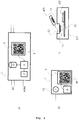
- Fig. 1a schematically shows a building services equipment 1 according to the invention.
- the building services equipment is preferably supplied via an external power supply AC (or else a supply with a / a DC voltage / Gleichstorm) and has connections KOM for a communication interface 2 (DALI) on.
- AC external power supply
- DALI communication interface 2
- the device 1 preferably has a control unit 3, which controls a display module 4 and thus controls and causes the display of the operating parameter information by a display unit 5 of the display module 4.
- the Display unit 5 may display the operating parameter information in the form of, for example, a machine-readable code (barcode, QR code, etc.).
- the display module 4 is thus functionally connected to the control unit 3.
- the device 1 can have a memory 6 and in particular a non-volatile memory in which the operating parameters are stored.
- the display module 4 displays the operating parameter information based on at least a portion of the operating parameters stored in the memory 6. For example, predetermined types of operating parameter information or also all operating parameter information or only specific operating parameter information regarding individual functions can be displayed by the display module 4.
- the control unit 3 is in particular a microcontroller, an ASIC, or IC. Furthermore, the device 1 preferably has the communication interface 2. This can be a communication interface for building technology / illuminant device buses, and in particular a DALI or DSI interface. The control unit 3 of the device can then also control the display module 4 in such a way that operating parameters received by the communication interface 2 are reproduced by the display unit of the display module.
- a lighting module 7 which also has a control unit 8. Also on the light source module 7, a display module 9 is provided, which has a display unit 10. On the display unit 10 can, for example, turn as a machine-readable code, for example, the LED operating current I LED and / or others for the lamp module 7 necessary operating parameters are displayed.
- the control unit 8 is functionally connected to the display module 9, analogously as described for the device.
- a lighting means 11, for example an LED, of the lighting module 7 is shown.
- the display module 4, 9, which is typically used only once in case of failure of the associated device 1, 7, may continue to be interchangeable and thus removed non-destructive device no longer functioning.
- the display module 4, 9 in another device 1, 7, for example, in a replacement device used.
- the display module 4, 9 may also be equipped with a memory (not shown) in which the operating parameter information is stored. If the display module 4, 9 then inserted into another device 1, 7, it can, as soon as it is connected to the control unit 3, 8 of the device, the operating parameter information to the control unit 3, 8 transmitted. The control unit 3, 8 can then adjust the operating parameters accordingly.
- the device 1, 7 thus preferably has a holder 12 for the display module 4, 9. It may be a clamping, plug and / or locking connection. It is also possible for the display module to be held on the device by means of an adhesive or magnetic connection.
- the device 1, 7 for connecting the display module 4, 9 with the control unit 3, 8, a contact surface 13, through which the display module 4, 9, which may have a corresponding contact surface 14, with the device 1, 7 and the control unit 3, 8 functional is connectable.
- the display module 4, 9 and connectors (not shown), such as connectors or clamp connectors have that can be accommodated in corresponding plug and / or Klemmverbindermethodn on the device 1, 7.
- the contact surface 13 of the device 1, 7 may be connected to a circuit board (printed circuit board, PCB) 15, on which the control unit 3, 8 is arranged.
- the display module 4, 9 is guided in the holder 12 of the device and is latched or held there.
- the connection with the control unit 3, 8 or with a board 15 arranged in the device can then also take place via a connection in that the contact surface 13 of the device is brought into contact with the contact surface 14 of the display module.
- the display unit 5, 10 is, as I said, preferably an e-paper. That is, a supply voltage of the display module provided by the device is needed to change the illustrated operating parameter information. However, no energy, i. no current or voltage required to maintain the display.
- the invention makes it easy to replace a device with another device having the same operating parameters as the device to be replaced.
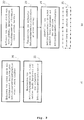
- Fig. 2a shows an example of the procedure for a replacement of a first device 1.7.
- step 20 we first detect an operating parameter information of a first device represented by the display module 4, 9.
- step 21 operating parameters are then set in a second device based on the acquired operating parameter information of the first device 1, 7.
- step 22 which corresponds to step 20
- step 24 which corresponds to step 24
- step 23 is provided, in which a transmission of the acquired operating parameter information to a server, or computer as central memory, takes place.
- the optional step 25 can take place, which provides for a transmission of the second, then configured device.
- the second device is also connected to the central memory, in particular server / computer. It is then possible that the second device sets the operating parameters by a communication between the central memory, in particular server / computer and the second device.
- the central memory, in particular server / computer can transmit the operating parameter information to the second device, or the second device can retrieve the operating parameter information from the server / computer.
- the communication can take place via an (IP) communication network.
- IP IP
- the second device can alternatively or additionally be made by direct connection (eg via USB) of the second device to the computer / server.
- the computer can retrieve the operating parameter information from a server and transmit the operating parameter information to the second device via the direct or a local connection.
- a lighting system which can have at least one building services equipment 1, in particular operating device for lighting means, and / or lighting module 7.
- the building services equipment 1 and / or the lighting module 7 can be designed to receive operating parameters via the communication interface 2, in particular a DALI interface.
- the illumination system furthermore has at least one reading device, which is designed for detecting 20 of an operating parameter information of a building technology device 1 and / or light-emitting module 7 represented by the display module 4, 9.
- the reader is connected to a communication network, wherein the communication network has a central memory, and wherein the central memory, preferably server, is adapted to store the operating parameter information.
- a method in which the read operating parameter information via a communication network to central memory, preferably a server, is transmitted.
- the second building services equipment 1 and / or lamp module 7 have a communication interface 2, wherein the communication interface 2 directly or indirectly with the Communication network is connected and the operating parameter information is detected via the communication interface 2 by querying the central memory, and based on the detected operating parameter information set the operating parameters in the second building services equipment 1 and / or light emitting module 7.
- the building services equipment 1 may have a communication interface 2, in particular a DALI interface or PLC interface (power line carrier interface).
- the building services equipment 1 can, for example, receive operating parameters from other building technology devices 1 ', 1 ", such as further operating devices, connected to the communication interface 2 via the communication interface 2.
- the display module 4, 9 can also display operating parameters received from other building services equipment via the communication interface 2 as operating parameter information
- Building services equipment 1 may for example also be a control device which can control other building services equipment via the communication interface 2, in particular a DALI interface or PLC interface (power line carrier interface), and can also receive operating parameter information or send it to this operating parameter information.
- the building services equipment can, for example, also be a central AC-DC converter unit or DC-DC converter unit, which feeds a DC bus (DC bus) n DC bus (DC bus), several operating devices or lamps can be supplied.
- the building services equipment as a central AC-DC converter unit or DC-DC converter unit and the operating devices or lamps can also receive operating parameters and send each other.
- the building services equipment as a central AC-DC converter unit or DC-DC converter unit can have a display unit 3 and thus output operating parameters.
Landscapes
- Engineering & Computer Science (AREA)
- Computer Networks & Wireless Communication (AREA)
- Circuit Arrangement For Electric Light Sources In General (AREA)
- Selective Calling Equipment (AREA)
Claims (15)
- Appareil de gestion de bâtiment (1), plus particulièrement appareil de commande pour moyen d'éclairage, comprenant un module d'affichage (4), qui est relié avec une unité de commande (3) de l'appareil de gestion de bâtiment (1), l'appareil de gestion de bâtiment (1) alimentant électriquement le module d'affichage (4),
caractérisé en ce que
le module d'affichage (4) est conçu pour afficher une information de paramètre de fonctionnement de l'appareil de gestion de bâtiment (1) même lors d'une défaillance de l'alimentation électrique par l'appareil de gestion de bâtiment (1) sans tension de maintien, le module d'affichage (4) comprenant une unité d'affichage (5) avec un papier électronique. - Appareil de gestion de bâtiment selon la revendication 1, caractérisé en ce que l'appareil de gestion de bâtiment (1) comprend une mémoire (6) et le module d'affichage (4) est conçu pour afficher les paramètres de fonctionnement enregistrés dans la mémoire (6) sous la forme de l'information de paramètre de fonctionnement.
- Appareil de gestion de bâtiment selon l'une des revendications précédentes, caractérisé en ce que l'unité de commande (3) est un microcontrôleur et l'unité de commande (3) contrôle le module d'affichage (4) pour l'affichage de l'information de paramètres de fonctionnement.
- Appareil de gestion de bâtiment selon l'une des revendications précédentes, caractérisé en ce que l'appareil de gestion de bâtiment (1) comprend une interface de communication (2), plus particulièrement une interface DALI et le module d'affichage (4) est conçu pour afficher les paramètres de fonctionnement reçus par l'intermédiaire de l'interface de communication (2) sous la forme d'une information de paramètres de fonctionnement.
- Appareil de gestion de bâtiment selon l'une des revendications précédentes, caractérisé en ce que le module d'affichage (4) est conçu pour afficher l'information de paramètres de fonctionnement sous la forme d'un code lisible par une machine et/ou sous la forme d'un texte en clair.
- Appareil de gestion de bâtiment selon l'une des revendications précédentes, caractérisé en ce que le module d'affichage (4) est maintenu de manière amovible sur l'appareil de gestion de bâtiment (1) et plus particulièrement est interchangeable et/ou peut être relié avec d'autres appareils de gestion de bâtiment (1).
- Appareil de gestion de bâtiment (1) selon l'une des revendications précédentes, l'appareil de gestion de bâtiment (1) étant un module de moyen d'éclairage (7).
- Module d'affichage (4, 9) comprenant au moins une surface de contact (14) et/ou des connecteurs par l'intermédiaire desquels le module d'affichage (4, 9) peut être relié avec une mémoire (6), une unité de commande (3, 8) et/ou une interface de communication (2) ou avec une platine (15) d'un appareil de gestion de bâtiment, plus particulièrement lorsque le module d'affichage est maintenu sur l'appareil de gestion de bâtiment, le module d'affichage (4, 9) étant conçu pour être alimenté électriquement par l'appareil de gestion de bâtiment lorsqu'il est relié avec l'appareil de gestion de bâtiment (1),
caractérisé en ce que
le module d'affichage (4, 9) est conçu pour afficher une information de paramètres de fonctionnement de l'appareil de gestion de bâtiment (1) même lors de la défaillance de l'alimentation électrique par l'appareil de gestion de bâtiment (1) sans tension de maintien, le module d'affichage (4, 9) comprenant une unité d'affichage (5, 10) avec papier électronique. - Module d'affichage selon la revendication 8, caractérisé en ce que l'unité d'affichage (5, 10) comprend une mémoire non volatile et le module d'affichage (4) est conçu pour enregistrer les paramètres de fonctionnement affichés dans la mémoire non volatile et plus particulièrement de sortir les paramètres de fonctionnement enregistrés lors de la liaison avec un appareil de gestion de bâtiment (1) et/ou un module de moyen d'éclairage (7).
- Module d'affichage selon l'une des revendications 1 à 7, caractérisé en ce que l'appareil de gestion de bâtiment (1) comprend un capteur, plus particulièrement un capteur optique, de préférence une caméra, qui est conçue pour détecter une information de paramètres de fonctionnement affichée par un autre module d'affichage selon la revendication 8 ou 9.
- Système d'éclairage comprenant au moins un appareil de gestion de bâtiment (1), plus particulièrement un appareil de commande pour moyen d'éclairage, selon l'une des revendications 1 à 7 ou 10, caractérisé en ce que l'appareil de gestion de bâtiment (1) est conçu pour recevoir des paramètres de fonctionnement par l'intermédiaire de l'interface de communication (2), plus particulièrement une interface DALI, le système d'éclairage comprenant en outre au moins un appareil de lecture qui est conçu pour la détection (20) d'une information de paramètres de fonctionnement représentée par le module d'affichage (4, 9) d'un appareil de gestion de bâtiment (1) et/ou d'un module de moyen d'éclairage (7), et l'appareil de lecture étant relié avec un réseau de communication, le réseau de communication comprenant une mémoire centrale et la mémoire centrale, de préférence un serveur, étant conçue pour enregistrer l'information de paramètres de fonctionnement.
- Procédé de réglage de paramètres de fonctionnement dans un appareil de gestion de bâtiment, caractérisé en ce que le procédé comprenant les étapes suivantes :- détection (20) d'une information de paramètres de fonctionnement représentée par un module d'affichage (4, 9) d'un appareil de gestion de bâtiment (1) selon l'une des revendications 1 à 7 ou 10, de préférence au moyen d'un appareil de lecture,- réglage (21) de paramètres de fonctionnement dans un deuxième appareil de gestion de bâtiment (7) et/ou module de moyen d'éclairage (1) sur la base de l'information de paramètres de fonctionnement détectée.
- Procédé selon la revendication 12, caractérisé en ce que l'information de paramètres de fonctionnement lue est transmise (23) par l'intermédiaire d'un réseau de communication à une mémoire centrale, de préférence un serveur, un envoi étant en outre effectué (25) par le deuxième appareil de gestion de bâtiment (1) et/ou le module de moyen d'éclairage (7) et en ce que le réglage (22) des paramètres de fonctionnement a lieu avant l'envoi, plus particulièrement par un fabricant de l'appareil de gestion de bâtiment (1) et/ou du module de moyen d'éclairage (7).
- Procédé selon la revendication 12, caractérisé en ce que le deuxième appareil de gestion de bâtiment (1) et/ou le module de moyen d'éclairage (7) comprend un capteur et l'information de paramètres de fonctionnement est détectée lors d'une interaction de l'utilisateur avec le capteur et, sur la base de l'information de paramètres de fonctionnement détectée, les paramètres de fonctionnement sont réglés dans le deuxième appareil de gestion de bâtiment (1) et/ou le module de moyen d'éclairage (7).
- Procédé selon la revendication 12, 13 ou 14, caractérisé en ce que l'information de paramètres de fonctionnement lue est transmise (23) par l'intermédiaire d'un réseau de communication à une mémoire centrale, de préférence un serveur, le deuxième appareil de gestion de bâtiment (1) et/ou le module de moyen d'éclairage (7) comprenant une interface de communication (2), l'interface de communication (2) étant reliée directement ou indirectement avec le réseau de communication et l'information de paramètres de fonctionnement étant détectée par l'intermédiaire de l'interface de communication (2) par une interrogation de la mémoire centrale et sur la base de l'information de paramètres de fonctionnement détectée, les paramètres de fonctionnement sont réglés dans le deuxième appareil de gestion de bâtiment (1) et/ou le module de moyen d'éclairage (7).
Applications Claiming Priority (2)
| Application Number | Priority Date | Filing Date | Title |
|---|---|---|---|
| DE102015210937.2A DE102015210937A1 (de) | 2015-06-15 | 2015-06-15 | Gebäudetechnikgerät mit Anzeigemodul |
| PCT/AT2016/050197 WO2016201470A1 (fr) | 2015-06-15 | 2016-06-14 | Appareil d'équipement technique du bâtiment, en particulier appareillage pour sources lumineuses |
Publications (2)
| Publication Number | Publication Date |
|---|---|
| EP3308609A1 EP3308609A1 (fr) | 2018-04-18 |
| EP3308609B1 true EP3308609B1 (fr) | 2019-12-04 |
Family
ID=56686591
Family Applications (1)
| Application Number | Title | Priority Date | Filing Date |
|---|---|---|---|
| EP16751456.1A Active EP3308609B1 (fr) | 2015-06-15 | 2016-06-14 | Appareil d'équipement technique du bâtiment, en particulier appareillage pour sources lumineuses |
Country Status (4)
| Country | Link |
|---|---|
| EP (1) | EP3308609B1 (fr) |
| AT (1) | AT16708U1 (fr) |
| DE (1) | DE102015210937A1 (fr) |
| WO (1) | WO2016201470A1 (fr) |
Family Cites Families (11)
| Publication number | Priority date | Publication date | Assignee | Title |
|---|---|---|---|---|
| US5490086A (en) * | 1992-03-06 | 1996-02-06 | Siemens Energy & Automation, Inc. | Plug-in ground fault monitor for a circuit breaker |
| DE102005022374A1 (de) * | 2005-05-13 | 2006-11-16 | Patent-Treuhand-Gesellschaft für elektrische Glühlampen mbH | Elektronisches Vorschaltgerät und Verfahren zum Einstellen von Betriebsbedingungen eines elektronischen Vorschaltgeräts |
| US7690802B2 (en) * | 2007-04-17 | 2010-04-06 | Cree, Inc. | Light emitting diode emergency lighting methods and apparatus |
| WO2009097900A1 (fr) * | 2008-02-08 | 2009-08-13 | Osram Gesellschaft mit beschränkter Haftung | Dispositif et procédé en particulier pour la commande d'une lampe |
| DE102008013610A1 (de) * | 2008-03-11 | 2009-10-08 | Osram Gesellschaft mit beschränkter Haftung | Leuchtvorrichtung mit auslesbaren Betriebsparametern |
| DE102008042185A1 (de) * | 2008-09-18 | 2010-03-25 | Robert Bosch Gmbh | Sicherheitssystem |
| DE102009017213B4 (de) * | 2009-04-09 | 2012-08-02 | Uwe Lindner | Notlicht mit intelligenten Zusatzmodulen |
| DE102010050192A1 (de) * | 2010-11-04 | 2012-05-10 | Stiebel Eltron Gmbh & Co. Kg | Verfahren zur Übermittlung von Daten und technische Vorrichtung |
| AP2014007841A0 (en) * | 2012-02-08 | 2014-07-31 | Visa Int Service Ass | A re-writable electronic label |
| DE102012210210A1 (de) * | 2012-04-30 | 2013-10-31 | Zumtobel Lighting Gmbh | Verfahren und System zum Abrufen von Betriebsdaten und/oder Betriebsinformationen eines Geräts |
| CN204697342U (zh) * | 2015-05-29 | 2015-10-07 | 桂林电子科技大学 | 智能灯光控制器 |
-
2015
- 2015-06-15 DE DE102015210937.2A patent/DE102015210937A1/de not_active Withdrawn
- 2015-07-07 AT ATGM203/2015U patent/AT16708U1/de not_active IP Right Cessation
-
2016
- 2016-06-14 WO PCT/AT2016/050197 patent/WO2016201470A1/fr not_active Ceased
- 2016-06-14 EP EP16751456.1A patent/EP3308609B1/fr active Active
Non-Patent Citations (1)
| Title |
|---|
| None * |
Also Published As
| Publication number | Publication date |
|---|---|
| DE102015210937A1 (de) | 2016-12-15 |
| EP3308609A1 (fr) | 2018-04-18 |
| AT16708U1 (de) | 2020-07-15 |
| WO2016201470A1 (fr) | 2016-12-22 |
Similar Documents
| Publication | Publication Date | Title |
|---|---|---|
| DE102006019144A1 (de) | Leuchte | |
| DE102014200297B4 (de) | Betriebsgerät und Kommunikationsadapter für den Außeneinsatz | |
| DE102012016266A1 (de) | Elektronisches Sensorgerät mit einem Funkslave-Speicherbauelement | |
| EP3069573B1 (fr) | Module de del, convertisseur de del et procédé permettant de faire fonctionner au moins une diode electroluminescente | |
| DE102017215125A1 (de) | Kommunikationsmodul und Beleuchtungs-Bussystem mit Netzwerkschnittstelle | |
| DE102017102597A1 (de) | Managementsystem für elektrische Vorrichtungen | |
| EP3958178A1 (fr) | Affectation d'adresse et configuration des composants d'un système d'éclairage au moyen de transpondeurs | |
| EP3354116B1 (fr) | Système d'éclairage | |
| DE10259391B4 (de) | Ortsgebundene Anpassung einer intelligenten Einheit | |
| EP3391713B1 (fr) | Protocolisation décentralisé des états de fonctionnement de composants de la technique du bâtiment | |
| EP3308609B1 (fr) | Appareil d'équipement technique du bâtiment, en particulier appareillage pour sources lumineuses | |
| EP1912343A2 (fr) | Paramétrage d'une unité intelligente par l'intermédiaire d'un dispositif d'alimentation de tension | |
| EP4152895A1 (fr) | Système d'éclairage | |
| WO2015110476A1 (fr) | Système adaptateur de communication, pour la technique de commande | |
| DE102015207331A1 (de) | Verfahren zur Adressierung von Leuchtmittelbetriebsgeräten | |
| EP2702834B1 (fr) | Dispositif de fonctionnement pour moyen d'éclairage et adaptateur pour alimenter ledit dispositif de fonctionnement en énergie | |
| EP1624729A1 (fr) | Procédé pour la installation d'un système de illumination | |
| DE102022100708A1 (de) | Verfahren zur Änderung von Softwaredaten eines Feldgerätes und eine ein solches Feldgerät umfassende Anlage | |
| EP2890057A1 (fr) | Assistance aux utilisateurs en domotique | |
| DE102019103889A1 (de) | Ein- und Auskoppelung von Daten und Datentransport über elektrische Versorgungsleitung von Beleuchtungssystemen | |
| AT18170U1 (de) | Adresszuweisung und Konfigurierung von Komponenten eines Beleuchtungssystems mittels Lichtsignalen | |
| DE202006011684U1 (de) | Leuchte | |
| AT15251U1 (de) | Leuchtmittelanordnung zur dynamischen Anzeige eines maschinenlesbaren Codes | |
| DE29701136U1 (de) | Busankoppler | |
| DE102014004434B4 (de) | Beleuchtungssystem und Betriebsverfahren mit einer Mehrzahl von gekoppelten Leuchten und Bewegungsmeldern |
Legal Events
| Date | Code | Title | Description |
|---|---|---|---|
| STAA | Information on the status of an ep patent application or granted ep patent |
Free format text: STATUS: THE INTERNATIONAL PUBLICATION HAS BEEN MADE |
|
| PUAI | Public reference made under article 153(3) epc to a published international application that has entered the european phase |
Free format text: ORIGINAL CODE: 0009012 |
|
| STAA | Information on the status of an ep patent application or granted ep patent |
Free format text: STATUS: REQUEST FOR EXAMINATION WAS MADE |
|
| 17P | Request for examination filed |
Effective date: 20171207 |
|
| AK | Designated contracting states |
Kind code of ref document: A1 Designated state(s): AL AT BE BG CH CY CZ DE DK EE ES FI FR GB GR HR HU IE IS IT LI LT LU LV MC MK MT NL NO PL PT RO RS SE SI SK SM TR |
|
| AX | Request for extension of the european patent |
Extension state: BA ME |
|
| DAV | Request for validation of the european patent (deleted) | ||
| DAX | Request for extension of the european patent (deleted) | ||
| STAA | Information on the status of an ep patent application or granted ep patent |
Free format text: STATUS: EXAMINATION IS IN PROGRESS |
|
| 17Q | First examination report despatched |
Effective date: 20181011 |
|
| GRAP | Despatch of communication of intention to grant a patent |
Free format text: ORIGINAL CODE: EPIDOSNIGR1 |
|
| STAA | Information on the status of an ep patent application or granted ep patent |
Free format text: STATUS: GRANT OF PATENT IS INTENDED |
|
| INTG | Intention to grant announced |
Effective date: 20190916 |
|
| GRAS | Grant fee paid |
Free format text: ORIGINAL CODE: EPIDOSNIGR3 |
|
| GRAA | (expected) grant |
Free format text: ORIGINAL CODE: 0009210 |
|
| STAA | Information on the status of an ep patent application or granted ep patent |
Free format text: STATUS: THE PATENT HAS BEEN GRANTED |
|
| AK | Designated contracting states |
Kind code of ref document: B1 Designated state(s): AL AT BE BG CH CY CZ DE DK EE ES FI FR GB GR HR HU IE IS IT LI LT LU LV MC MK MT NL NO PL PT RO RS SE SI SK SM TR |
|
| REG | Reference to a national code |
Ref country code: GB Ref legal event code: FG4D Free format text: NOT ENGLISH |
|
| REG | Reference to a national code |
Ref country code: CH Ref legal event code: EP |
|
| REG | Reference to a national code |
Ref country code: AT Ref legal event code: REF Ref document number: 1211196 Country of ref document: AT Kind code of ref document: T Effective date: 20191215 |
|
| REG | Reference to a national code |
Ref country code: DE Ref legal event code: R096 Ref document number: 502016007886 Country of ref document: DE |
|
| REG | Reference to a national code |
Ref country code: IE Ref legal event code: FG4D Free format text: LANGUAGE OF EP DOCUMENT: GERMAN |
|
| REG | Reference to a national code |
Ref country code: CH Ref legal event code: NV Representative=s name: VALIPAT S.A. C/O BOVARD SA NEUCHATEL, CH |
|
| REG | Reference to a national code |
Ref country code: NL Ref legal event code: MP Effective date: 20191204 |
|
| REG | Reference to a national code |
Ref country code: LT Ref legal event code: MG4D |
|
| PG25 | Lapsed in a contracting state [announced via postgrant information from national office to epo] |
Ref country code: SE Free format text: LAPSE BECAUSE OF FAILURE TO SUBMIT A TRANSLATION OF THE DESCRIPTION OR TO PAY THE FEE WITHIN THE PRESCRIBED TIME-LIMIT Effective date: 20191204 Ref country code: LV Free format text: LAPSE BECAUSE OF FAILURE TO SUBMIT A TRANSLATION OF THE DESCRIPTION OR TO PAY THE FEE WITHIN THE PRESCRIBED TIME-LIMIT Effective date: 20191204 Ref country code: GR Free format text: LAPSE BECAUSE OF FAILURE TO SUBMIT A TRANSLATION OF THE DESCRIPTION OR TO PAY THE FEE WITHIN THE PRESCRIBED TIME-LIMIT Effective date: 20200305 Ref country code: LT Free format text: LAPSE BECAUSE OF FAILURE TO SUBMIT A TRANSLATION OF THE DESCRIPTION OR TO PAY THE FEE WITHIN THE PRESCRIBED TIME-LIMIT Effective date: 20191204 Ref country code: NO Free format text: LAPSE BECAUSE OF FAILURE TO SUBMIT A TRANSLATION OF THE DESCRIPTION OR TO PAY THE FEE WITHIN THE PRESCRIBED TIME-LIMIT Effective date: 20200304 Ref country code: FI Free format text: LAPSE BECAUSE OF FAILURE TO SUBMIT A TRANSLATION OF THE DESCRIPTION OR TO PAY THE FEE WITHIN THE PRESCRIBED TIME-LIMIT Effective date: 20191204 Ref country code: BG Free format text: LAPSE BECAUSE OF FAILURE TO SUBMIT A TRANSLATION OF THE DESCRIPTION OR TO PAY THE FEE WITHIN THE PRESCRIBED TIME-LIMIT Effective date: 20200304 |
|
| PG25 | Lapsed in a contracting state [announced via postgrant information from national office to epo] |
Ref country code: RS Free format text: LAPSE BECAUSE OF FAILURE TO SUBMIT A TRANSLATION OF THE DESCRIPTION OR TO PAY THE FEE WITHIN THE PRESCRIBED TIME-LIMIT Effective date: 20191204 Ref country code: HR Free format text: LAPSE BECAUSE OF FAILURE TO SUBMIT A TRANSLATION OF THE DESCRIPTION OR TO PAY THE FEE WITHIN THE PRESCRIBED TIME-LIMIT Effective date: 20191204 |
|
| PG25 | Lapsed in a contracting state [announced via postgrant information from national office to epo] |
Ref country code: AL Free format text: LAPSE BECAUSE OF FAILURE TO SUBMIT A TRANSLATION OF THE DESCRIPTION OR TO PAY THE FEE WITHIN THE PRESCRIBED TIME-LIMIT Effective date: 20191204 |
|
| PG25 | Lapsed in a contracting state [announced via postgrant information from national office to epo] |
Ref country code: RO Free format text: LAPSE BECAUSE OF FAILURE TO SUBMIT A TRANSLATION OF THE DESCRIPTION OR TO PAY THE FEE WITHIN THE PRESCRIBED TIME-LIMIT Effective date: 20191204 Ref country code: CZ Free format text: LAPSE BECAUSE OF FAILURE TO SUBMIT A TRANSLATION OF THE DESCRIPTION OR TO PAY THE FEE WITHIN THE PRESCRIBED TIME-LIMIT Effective date: 20191204 Ref country code: PT Free format text: LAPSE BECAUSE OF FAILURE TO SUBMIT A TRANSLATION OF THE DESCRIPTION OR TO PAY THE FEE WITHIN THE PRESCRIBED TIME-LIMIT Effective date: 20200429 Ref country code: NL Free format text: LAPSE BECAUSE OF FAILURE TO SUBMIT A TRANSLATION OF THE DESCRIPTION OR TO PAY THE FEE WITHIN THE PRESCRIBED TIME-LIMIT Effective date: 20191204 Ref country code: ES Free format text: LAPSE BECAUSE OF FAILURE TO SUBMIT A TRANSLATION OF THE DESCRIPTION OR TO PAY THE FEE WITHIN THE PRESCRIBED TIME-LIMIT Effective date: 20191204 Ref country code: EE Free format text: LAPSE BECAUSE OF FAILURE TO SUBMIT A TRANSLATION OF THE DESCRIPTION OR TO PAY THE FEE WITHIN THE PRESCRIBED TIME-LIMIT Effective date: 20191204 |
|
| PG25 | Lapsed in a contracting state [announced via postgrant information from national office to epo] |
Ref country code: IS Free format text: LAPSE BECAUSE OF FAILURE TO SUBMIT A TRANSLATION OF THE DESCRIPTION OR TO PAY THE FEE WITHIN THE PRESCRIBED TIME-LIMIT Effective date: 20200404 Ref country code: SK Free format text: LAPSE BECAUSE OF FAILURE TO SUBMIT A TRANSLATION OF THE DESCRIPTION OR TO PAY THE FEE WITHIN THE PRESCRIBED TIME-LIMIT Effective date: 20191204 Ref country code: SM Free format text: LAPSE BECAUSE OF FAILURE TO SUBMIT A TRANSLATION OF THE DESCRIPTION OR TO PAY THE FEE WITHIN THE PRESCRIBED TIME-LIMIT Effective date: 20191204 |
|
| REG | Reference to a national code |
Ref country code: DE Ref legal event code: R097 Ref document number: 502016007886 Country of ref document: DE |
|
| PLBE | No opposition filed within time limit |
Free format text: ORIGINAL CODE: 0009261 |
|
| STAA | Information on the status of an ep patent application or granted ep patent |
Free format text: STATUS: NO OPPOSITION FILED WITHIN TIME LIMIT |
|
| PG25 | Lapsed in a contracting state [announced via postgrant information from national office to epo] |
Ref country code: DK Free format text: LAPSE BECAUSE OF FAILURE TO SUBMIT A TRANSLATION OF THE DESCRIPTION OR TO PAY THE FEE WITHIN THE PRESCRIBED TIME-LIMIT Effective date: 20191204 |
|
| 26N | No opposition filed |
Effective date: 20200907 |
|
| PG25 | Lapsed in a contracting state [announced via postgrant information from national office to epo] |
Ref country code: SI Free format text: LAPSE BECAUSE OF FAILURE TO SUBMIT A TRANSLATION OF THE DESCRIPTION OR TO PAY THE FEE WITHIN THE PRESCRIBED TIME-LIMIT Effective date: 20191204 Ref country code: PL Free format text: LAPSE BECAUSE OF FAILURE TO SUBMIT A TRANSLATION OF THE DESCRIPTION OR TO PAY THE FEE WITHIN THE PRESCRIBED TIME-LIMIT Effective date: 20191204 |
|
| PG25 | Lapsed in a contracting state [announced via postgrant information from national office to epo] |
Ref country code: MC Free format text: LAPSE BECAUSE OF FAILURE TO SUBMIT A TRANSLATION OF THE DESCRIPTION OR TO PAY THE FEE WITHIN THE PRESCRIBED TIME-LIMIT Effective date: 20191204 Ref country code: IT Free format text: LAPSE BECAUSE OF FAILURE TO SUBMIT A TRANSLATION OF THE DESCRIPTION OR TO PAY THE FEE WITHIN THE PRESCRIBED TIME-LIMIT Effective date: 20191204 |
|
| PG25 | Lapsed in a contracting state [announced via postgrant information from national office to epo] |
Ref country code: LU Free format text: LAPSE BECAUSE OF NON-PAYMENT OF DUE FEES Effective date: 20200614 |
|
| REG | Reference to a national code |
Ref country code: BE Ref legal event code: MM Effective date: 20200630 |
|
| REG | Reference to a national code |
Ref country code: DE Ref legal event code: R084 Ref document number: 502016007886 Country of ref document: DE |
|
| PG25 | Lapsed in a contracting state [announced via postgrant information from national office to epo] |
Ref country code: IE Free format text: LAPSE BECAUSE OF NON-PAYMENT OF DUE FEES Effective date: 20200614 |
|
| PG25 | Lapsed in a contracting state [announced via postgrant information from national office to epo] |
Ref country code: BE Free format text: LAPSE BECAUSE OF NON-PAYMENT OF DUE FEES Effective date: 20200630 |
|
| PG25 | Lapsed in a contracting state [announced via postgrant information from national office to epo] |
Ref country code: TR Free format text: LAPSE BECAUSE OF FAILURE TO SUBMIT A TRANSLATION OF THE DESCRIPTION OR TO PAY THE FEE WITHIN THE PRESCRIBED TIME-LIMIT Effective date: 20191204 Ref country code: MT Free format text: LAPSE BECAUSE OF FAILURE TO SUBMIT A TRANSLATION OF THE DESCRIPTION OR TO PAY THE FEE WITHIN THE PRESCRIBED TIME-LIMIT Effective date: 20191204 Ref country code: CY Free format text: LAPSE BECAUSE OF FAILURE TO SUBMIT A TRANSLATION OF THE DESCRIPTION OR TO PAY THE FEE WITHIN THE PRESCRIBED TIME-LIMIT Effective date: 20191204 |
|
| PG25 | Lapsed in a contracting state [announced via postgrant information from national office to epo] |
Ref country code: MK Free format text: LAPSE BECAUSE OF FAILURE TO SUBMIT A TRANSLATION OF THE DESCRIPTION OR TO PAY THE FEE WITHIN THE PRESCRIBED TIME-LIMIT Effective date: 20191204 |
|
| REG | Reference to a national code |
Ref country code: AT Ref legal event code: MM01 Ref document number: 1211196 Country of ref document: AT Kind code of ref document: T Effective date: 20210614 |
|
| PG25 | Lapsed in a contracting state [announced via postgrant information from national office to epo] |
Ref country code: AT Free format text: LAPSE BECAUSE OF NON-PAYMENT OF DUE FEES Effective date: 20210614 |
|
| P01 | Opt-out of the competence of the unified patent court (upc) registered |
Effective date: 20230530 |
|
| PGFP | Annual fee paid to national office [announced via postgrant information from national office to epo] |
Ref country code: FR Payment date: 20230622 Year of fee payment: 8 |
|
| PGFP | Annual fee paid to national office [announced via postgrant information from national office to epo] |
Ref country code: GB Payment date: 20240618 Year of fee payment: 9 |
|
| PGFP | Annual fee paid to national office [announced via postgrant information from national office to epo] |
Ref country code: CH Payment date: 20240701 Year of fee payment: 9 |
|
| PG25 | Lapsed in a contracting state [announced via postgrant information from national office to epo] |
Ref country code: FR Free format text: LAPSE BECAUSE OF NON-PAYMENT OF DUE FEES Effective date: 20240630 |
|
| PGFP | Annual fee paid to national office [announced via postgrant information from national office to epo] |
Ref country code: DE Payment date: 20250626 Year of fee payment: 10 |
|
| REG | Reference to a national code |
Ref country code: CH Ref legal event code: H13 Free format text: ST27 STATUS EVENT CODE: U-0-0-H10-H13 (AS PROVIDED BY THE NATIONAL OFFICE) Effective date: 20260127 |
|
| GBPC | Gb: european patent ceased through non-payment of renewal fee |
Effective date: 20250614 |
|
| PG25 | Lapsed in a contracting state [announced via postgrant information from national office to epo] |
Ref country code: GB Free format text: LAPSE BECAUSE OF NON-PAYMENT OF DUE FEES Effective date: 20250614 |
|
| PG25 | Lapsed in a contracting state [announced via postgrant information from national office to epo] |
Ref country code: CH Free format text: LAPSE BECAUSE OF NON-PAYMENT OF DUE FEES Effective date: 20250630 |