EP3308671A2 - Balai - Google Patents
Balai Download PDFInfo
- Publication number
- EP3308671A2 EP3308671A2 EP17183690.1A EP17183690A EP3308671A2 EP 3308671 A2 EP3308671 A2 EP 3308671A2 EP 17183690 A EP17183690 A EP 17183690A EP 3308671 A2 EP3308671 A2 EP 3308671A2
- Authority
- EP
- European Patent Office
- Prior art keywords
- broom
- bristle
- bristles
- area
- trailing edge
- Prior art date
- Legal status (The legal status is an assumption and is not a legal conclusion. Google has not performed a legal analysis and makes no representation as to the accuracy of the status listed.)
- Granted
Links
Images




Classifications
-
- A—HUMAN NECESSITIES
- A46—BRUSHWARE
- A46B—BRUSHES
- A46B5/00—Brush bodies; Handles integral with brushware
- A46B5/0004—Additional brush head
- A46B5/0012—Brushes with two or more heads on the same end of a handle for simultaneous use, e.g. cooperating with each-other
-
- A—HUMAN NECESSITIES
- A46—BRUSHWARE
- A46B—BRUSHES
- A46B5/00—Brush bodies; Handles integral with brushware
- A46B5/002—Brush bodies; Handles integral with brushware having articulations, joints or flexible portions
- A46B5/0033—Brush bodies; Handles integral with brushware having articulations, joints or flexible portions bending or stretching or collapsing
- A46B5/0045—Brushes articulated with more than one hinge
-
- A—HUMAN NECESSITIES
- A46—BRUSHWARE
- A46B—BRUSHES
- A46B5/00—Brush bodies; Handles integral with brushware
- A46B5/002—Brush bodies; Handles integral with brushware having articulations, joints or flexible portions
- A46B5/0054—Brush bodies; Handles integral with brushware having articulations, joints or flexible portions designed to allow relative positioning of the head to body
-
- A—HUMAN NECESSITIES
- A46—BRUSHWARE
- A46B—BRUSHES
- A46B9/00—Arrangements of the bristles in the brush body
- A46B9/02—Position or arrangement of bristles in relation to surface of the brush body, e.g. inclined, in rows, in groups
-
- A—HUMAN NECESSITIES
- A46—BRUSHWARE
- A46B—BRUSHES
- A46B2200/00—Brushes characterized by their functions, uses or applications
- A46B2200/30—Brushes for cleaning or polishing
- A46B2200/302—Broom
Definitions
- the invention relates to a broom comprising a bristle carrier body and a handle attached in its central region.
- the phenomenon is known that with increasing width of the broom, so length of the bristle carrier body, with stiff bristles the broom with the bristles no longer evenly rests when sweeping on the ground, but vibrates around a running in the sweeping axis, due to the - depending on the irregularities of the ground and unevenly applied force of the user - once at the left and once at the right end of the bristle carrier body from the ground a higher or lower force against the bristle carrier body is applied, and thereby one of the ends is pushed up and at Movement in the sweeping direction can also lift off the ground.
- the space required for storing such a broom is much greater than for a conventional broom with a straight bristle carrier body.
- a broom has very soft, so very elastic-elastic, bristles, the problem continues to occur, that in most cases a sweeping is possible only in the drawing direction, and less and less in the sliding direction, since when pushing the applied force of User is applied obliquely down on the broom, and thereby the bristles bend and brake hard on the ground, while pulling almost no force component is applied vertically down to the broom, except the weight of the being.
- Another problem with almost all broom types is the sweeping of an edge between a horizontal and a vertical surface. This problem is greater, the shorter the bristles are and the less obliquely outward they protrude from the broom head or its base body.
- a broom can be used with a greater width and thus greater sweeping, without the hindering rocking or lifting off the ground in areas of the broom.
- the bristle area runs parallel to its trailing edge and thus, seen in the sweeping direction, the bristle area is everywhere the same width. This applies at least to the left region and / or the right region of the bristle region separately, preferably over the entire bristle region.
- a contiguous contour of a leading edge and a trailing edge is preferably one complete sine wave results.
- the shape of the left area is identical to the shape of the right area, and preferably left and right range from the respective outer end to the longitudinal center of the bristle area, in particular of the broom head.
- the deflection should be between 2 % and 20 %, better still between 3 % and 12 %, better between 5 % and 10 %, better between 6 % and 9 % of the transversely measured width of this curved area, So with a cavity the depth of the cavity and with a convex edge the height of the convex deflection.
- this deflection of the convex shape or depth of the cavity should range between 0.3 cm and 4.0 cm, in particular between 0.5 cm and 2.5 cm, in particular between 1.0 cm and 2.0 cm As tests have shown, and remarkably, these absolute values are hardly dependent on the width of the curved contour.
- the point at which the curvature of the bristle area changes is the center of the bristle area, especially in the case of a bristle area of equal width.
- the bristle area is thus point-symmetrical designed to the center, ie the intersection of the longitudinal direction of the sweeping direction with the viewed in the top view center line of the bristle area.
- the individual curved contours ie cavities or convex contours, are preferably formed laterally symmetrically to the longitudinal direction through their lowest or highest point, which has proved to be particularly advantageous in tests, or more curved in the outer region than to the middle of the bristle region out.
- the bristle carrier body to which the bristles are attached either over the entire width - ie extending in the transverse direction - be integrally formed, or consist of one or more separate left and right carrier body parts, which are then fixed directly or indirectly against each other.
- the bristle carrier body is preferably fastened to a head base body on which the attachment device for the stem is arranged, and preferably positively secured to this head base body.
- the attachment device for the stem is preferably not a rigid attachment device, but designed as a joint, so that the attached to the one part of the joint stem relative to the attached to the other part of the joint bristle support body or in particular a head body adjustable: Preferably, an adjustability given in a longitudinally extending vertically vertical longitudinal plane, whereby the inclination of the stem can be adapted to the size of the user to each lead the bristles as perpendicular to the ground when sweeping or the flat bottom of the bristle support body as parallel to the ground respectively.
- the attachment of the bristle-carrying body which preferably consists of the same material as the bristles, preferably takes place in a form-fitting manner on the head base body by means of the inherent elasticity of the bristle-supporting body, considered in cross-section example, C-shaped and can be mounted on a matching contour of the head body.
- the fastening device is arranged, on which the handle is attached.
- the two support body parts may be designed relative to one another or relative to the part arranged therebetween, such as the fastening device preferably pivotable about a vertical axis and in the respective desired pivot position also adjustable.
- the two support body parts at an angle to each other, so not aligned with respect to their main extension direction, or the two support body parts can be adjusted in alignment with each other with respect to their main directions of extension, but at an angle deviating from 90 ° to the sweeping direction.
- the joint of the stem also in a transverse vertical plane, which is so beispielswese by the viewed in the direction of main extension direction of the broom head on the one hand and the stem on the other hand to pivot on the other hand ,
- This allows the broom head to be pivoted up to a position parallel to the stem, which greatly reduces the space required for storage, especially in very wide broom.
- the stem is preferably connected only at one point with the broom head, so that only a single such attachment device between broom head and stem is present, preferably in the longitudinal center of the broom head, ie symmetrically on the broom head.
- the at least one stem is secured to the broom head via at least two transversely spaced locations, that is, there are two laterally spaced attachment devices, each of which may be configured as described above.
- the two fastening devices are then arranged on the left and right of the longitudinal center and symmetrically to the latter on the broom head, in particular the head base body.
- Either the handle is then a single handle, which however is fork-shaped with two prongs, at least in its front region, and each of the prongs is fixed with its free end to one of the fastening devices.
- it may also be two stems, which are connected to each other in particular via a cross brace and thus may be designed for example U-shaped or a single stem is fork-shaped in its entire length. Then the connecting leg of the U-shape can also be used to guide the broom, so as a handle.
- the bristles should preferably have a relatively low flexural strength transverse to the skin extension direction of the bristles, preferably having a hardness between 50 shore and 70 shore, more preferably between 55 shore and 65 shore.
- bristles made of a rubber-like material, in particular of synthetic rubber or natural rubber are particularly well suited.
- Such rubbery bristles may be integrally formed together with the bristle support body, for example by injection molding.
- the cross section of the bristles should have at least one pointing in the sliding direction and / or in the drawing direction of the broom indentation, at least in the lower end region, the intermediate angle between the flanks of the indentation - regardless of whether the contour is rounded or angular - preferably larger than 40 ° should preferably be 50 °, in particular even greater than 70 °, preferably greater than 90 °, but preferably not greater than 100 °.
- transversely extending rows of bristles of one kind may cross-sectional orientation follow in the sweeping direction subsequent rows with the other bristle orientation, or in such a transverse cross-sectional orientation bristles of one and bristles of the other cross-sectional orientation can be arranged by each other, in particular alternately.
- the concave trailing edge of the bristle area should be provided in the viewing direction of the user in the right area.
- the stem should be pivotable in the vertical longitudinal plane of a request from the broom head back to a request of the broom head forward.
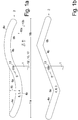
- FIGS. 1a and 1b show in the plan view from above each a broom head 2, which extends in the transverse direction 11 , being defined as the transverse direction 11 that direction in which viewed in the plan view of the broom head 2 has its greatest extent, so its main extension direction (2 ') , in particular its largest ingestible extension, which in the FIGS. 2a, b is important.
- Lying in the horizontal plane Perpendicular to the transverse direction 11 is the reverse direction 10, whether the shift direction 10 a or the pulling direction 10 b, depending on whether the broom head 2 is pushed or pulled during sweeping by means of the stem. 1
- a head base 8 on which, preferably below, the bristle support body 3 is fixed - over the entire extent in the transverse direction 11, a preferably constant width.
- the bristle area 4 as viewed in the top view, comprises bristles 7 on the bristle carrier body 3 , extends over approximately the same area as the head base body 8 and / or the bristle carrier body 3 in the plan view consider why their areas are assumed to be the same size for the purposes of the supervisory presentations.
- Fig. 1a As well in Fig. 1a as well as in Fig. 1b has in the left area 11 a, with respect to the extension in the transverse direction 11 of the left half 11 a, the bristle area 4, the concave front edge 4 a and an analogous shaped, convex trailing edge 4 b, while in the right area 11 b, the right half 11 b of the bristle portion 4 is exactly reversed, ie a convex front edge 4 a and a particular analog shaped concave trailing edge. 4 b is present.
- the shape of the leading edges and trailing edges is in Fig. 1a a curved line, which either has a uniform curvature and thus is a circular arc segment, or has a changing curvature and in particular represents a sine curve, which applies to both the continuous front edge 4 a and the continuous trailing edge 4 b.
- the bristle area 4 and / or the bristle carrier body 3 and / or the head base body 8 have the shape of a sinusoidal band or a band composed of two counter-arcuate circular arc segments.
- the Fig. 1b differs in terms of the viewed in the top view bristle area 4 in that the leading edges 4 a and 4 b are no curved, but angled contours, so so the cavities 6 a in the left area of the front edge and 6 b in the right area of the trailing edge V-shaped contour, and also the corresponding opposite edges of the same area form an analogous convex contour.
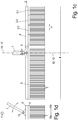
- both in Fig. 1a as well as in Fig. 1b is in the middle of the extension in the transverse direction of the head base 8 on top of this head base 8 a broom handle 1 attached via a fastening device 5.
- the fastening device 5 is formed as a uniaxial joint, so that the stem 1 relative to the head base body 8 about a transverse axis 11 extending pivot axis 13 is pivotable and thereby depending on the size of the user optimal inclination of the stem 1 - as in the side view of Fig. 1d to recognize - can be adjusted.
- either the stem 1 or the fastening device 5 can be pivotable about a vertical axis 12 or the course direction 12 'of the stem 1 .
- the bristles 7 are integrally formed together with the bristle support body 3 , which is fixed to the underside of the head base 8 .
- the bristle support body 3 in the transverse direction 11 in one piece over the entire extent of the head base body 8 extend -wie in the left half of Fig. 1c shown, or the bristle support body 3 may consist of several, in the transverse direction 11 adjoining, supporting body parts 3.1, 3.2, 3.3 , which are each attached separately to the head base body 8 .
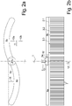
- the design according to the FIGS. 2a, 2b is different from the one of Fig. 1 a . 1 c, 1 d in that the head base 8 itself consists of two body parts 8 a, 8 b, viewed in the transverse direction 11 with their mutually facing ends in the plan view closely adjoin one another, so that the mutually facing end portions of the two body parts 8 a, 8 b each with the mounting base 5 a of the fastening device 5 articulated about each vertical axis 12, in particular the vertical, are attached.
- the left and the right main body part 8 a, 8 b can be set and adjusted to each other in an almost arbitrary angle in the plan view.
- the handle 1 is then pivotable about a horizontal lying, preferably in the transverse direction 11 extending transverse axis 13 .
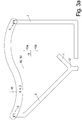
- each attachment device 5 is fixed to the head base member 8 instead of a central fastening device in its respective end region in the transverse direction 11 is provided for movably securing the free end of a shaft 1, and in particular pivotable about an axis extending in the transverse direction 11 of the pivot axis. 13
- it can be an arcuate, in particular U-shaped, handle 1 with two free ends, which are spaced so that they can be fixed in each case in one of the fastening devices 5 .
- the left half shows the FIGS. 3a . 3b a stem which forks in the front region and in each case one of the free ends of one of the prongs of this fork in each case one of the fastening devices 5 movably secured, preferably pivotable about a particular lying in the transverse direction 13 pivot axis can be.
- the user thus grips the central rear portion of the stem 1 as well as a stem, as in the FIGS. 1a, 1b is shown, and can thereby apply only small torsional forces about the extension direction 12 'of the stem 1 .
- FIGS. 4a, 4b show a broom head consisting of two pivotable relative to each other about a vertical axis 12 main body parts 8 a, 8 b as in the design according to the FIGS. 2 a, 2 b and with appropriate, viewed in the supervision, shaping the entire broom head.
- Fig. 4a, 4b - Instead of a single central fastening device - on the main body parts 8 a, 8 b each have a fastening device 5 for the end of a stem 1 or two separate stems 1 , respectively at the transverse direction 11 outwardly facing end portion of each of the two main body Parts 8 a, 8 b.
- the two main body parts 8 a, 8 b can be directly connected to each other articulated about a vertical axis 12 or - as shown - via a connecting part 14 to which each of the base body parts 8 a, 8 b is attached to a separate vertical axis 12 swivel ,
- the fastening devices 5 can also be arranged in the transverse direction 11 movable to the respective body parts 8 a, 8 b be.
- both the front edge 4 a and the trailing edge 4 b are concave-shaped, in particular identically concave.
- an opening in the form of an also lenticular inner contour can also be present in the middle of the region with the convex front edge and trailing edge-in particular centric to this lenticular outer contour.
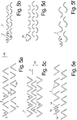
- FIGS. 5a to 5h the cross-sections of the individual bristles 7 are shown with a thickness that is constant in the course of this cross-section, but this is not absolutely necessary for the purposes of the present invention.
- the cross sections of the bristles 7 are V-shaped, so that the two legs 14 of this V-shape meet at an acute intermediate angle 15 , which is preferably between 40 and 110 °.
- the bristles 5 are arranged in the sweeping direction 10 rows arranged one behind the other, and in Fig. 5a within the rows next to each other alternately the V-shaped cross sections of the bristles 7 once arranged with the indentation 9 forward and once with the indentation 9 to the rear.
- the bristles 7 of the successive rows in the sweeping direction 10 are offset from one row to the next, so that a bristle 7 with its longitudinal center 7 ' always in the sweeping direction 10 is aligned with the gap of two adjacent bristles 7 in an adjacent row.
- FIGS. 5b, 5d show the same arrangement of the bristles 7 as the figures 5 a, 5 c, but with a cross-sectional shape of the individual bristles 7, which is not V-shaped, but arcuate or cup-shaped. Tangents applied to the ends of the shell mold have an intermediate angle 16, which is preferably between 40 and 110 °.
- Fig. 5e shows a shape of the bristle cross-section, the on the V-shape of FIGS. 5 a, 5 c
- a third leg 14 and all of the three adjoining legs are at an angle 15 to each other, so that each bristle 7 has a forward facing recess 9 and adjacent spaced a second, rearwardly facing indentation 9 .
- the bristles 7 are identically formed and arranged identically. Again, from one row to the next, the bristles 7 are each arranged in gap to the adjacent row.
- Fig. 5f In which zigzag-shaped instead of three legs present a bristle cross section in the form of a full sine wave, or from two adjacent circular arc segments, and thus also in each bristle both 7 a forward facing as well as a rear facing indentation 9 is present.
- Fig. 5g shows bristles 7, whose cross-section is W-shaped, ie from two adjoining interconnected V-cross sections according to Fig. 5 a, so that then a total of four legs 14 form a zigzag line, each with equal angles 15 between the adjacent legs 14th
- these bristles 7 are each arranged in an identical position next to each other, and in all rows with the same arrangement of the cross sections of the bristles with respect to the direction of their central unilateral indentation 9 in the same direction, be it forward or backward.
- the bristles of a row are arranged with the central indentation 9 in one direction and the bristles of the next adjacent row with alignment of the central indentation 9 in the other direction.
- the bristles 7 are offset from each other in the transverse direction 11 from row to row such that one bristle 7 is aligned with the gap between two adjacent bristles 7 of the next adjacent row.
- each of these bristles 7 thus consists of three merging into each other circle segments or 1.5 sine waves.
Landscapes
- Cleaning Implements For Floors, Carpets, Furniture, Walls, And The Like (AREA)
Priority Applications (4)
| Application Number | Priority Date | Filing Date | Title |
|---|---|---|---|
| SM20240276T SMT202400276T1 (it) | 2016-07-29 | 2017-07-28 | Scopa |
| SI201731531T SI3308671T1 (sl) | 2016-07-29 | 2017-07-28 | Metla |
| RS20240751A RS65723B1 (sr) | 2016-07-29 | 2017-07-28 | Metla |
| HRP20240954TT HRP20240954T1 (hr) | 2016-07-29 | 2017-07-28 | Metla |
Applications Claiming Priority (1)
| Application Number | Priority Date | Filing Date | Title |
|---|---|---|---|
| DE102016114012.0A DE102016114012B4 (de) | 2016-07-29 | 2016-07-29 | Besen |
Publications (3)
| Publication Number | Publication Date |
|---|---|
| EP3308671A2 true EP3308671A2 (fr) | 2018-04-18 |
| EP3308671A3 EP3308671A3 (fr) | 2018-08-08 |
| EP3308671B1 EP3308671B1 (fr) | 2024-05-29 |
Family
ID=59501265
Family Applications (1)
| Application Number | Title | Priority Date | Filing Date |
|---|---|---|---|
| EP17183690.1A Active EP3308671B1 (fr) | 2016-07-29 | 2017-07-28 | Balai |
Country Status (13)
| Country | Link |
|---|---|
| EP (1) | EP3308671B1 (fr) |
| DE (1) | DE102016114012B4 (fr) |
| DK (1) | DK3308671T3 (fr) |
| ES (1) | ES2982729T3 (fr) |
| FI (1) | FI3308671T3 (fr) |
| HR (1) | HRP20240954T1 (fr) |
| HU (1) | HUE067528T2 (fr) |
| LT (1) | LT3308671T (fr) |
| PL (1) | PL3308671T3 (fr) |
| PT (1) | PT3308671T (fr) |
| RS (1) | RS65723B1 (fr) |
| SI (1) | SI3308671T1 (fr) |
| SM (1) | SMT202400276T1 (fr) |
Family Cites Families (3)
| Publication number | Priority date | Publication date | Assignee | Title |
|---|---|---|---|---|
| DE29516571U1 (de) * | 1995-10-20 | 1996-01-11 | Huller, Joachim, 77716 Fischerbach | Borstenausführung und deren Besteckung für Borstenwaren, insbesondere für Besen, Bürsten, Schrubber, Pinsel o.dgl. |
| US7690070B2 (en) * | 2005-09-24 | 2010-04-06 | Man-Young Jung | Bi-pole cleaning device |
| US8739348B1 (en) * | 2012-12-17 | 2014-06-03 | Gordon Martin Currier | Broom with curved or angled head |
-
2016
- 2016-07-29 DE DE102016114012.0A patent/DE102016114012B4/de active Active
-
2017
- 2017-07-28 HR HRP20240954TT patent/HRP20240954T1/hr unknown
- 2017-07-28 SI SI201731531T patent/SI3308671T1/sl unknown
- 2017-07-28 HU HUE17183690A patent/HUE067528T2/hu unknown
- 2017-07-28 PL PL17183690.1T patent/PL3308671T3/pl unknown
- 2017-07-28 EP EP17183690.1A patent/EP3308671B1/fr active Active
- 2017-07-28 DK DK17183690.1T patent/DK3308671T3/da active
- 2017-07-28 RS RS20240751A patent/RS65723B1/sr unknown
- 2017-07-28 PT PT171836901T patent/PT3308671T/pt unknown
- 2017-07-28 SM SM20240276T patent/SMT202400276T1/it unknown
- 2017-07-28 LT LTEP17183690.1T patent/LT3308671T/lt unknown
- 2017-07-28 FI FIEP17183690.1T patent/FI3308671T3/fi active
- 2017-07-28 ES ES17183690T patent/ES2982729T3/es active Active
Also Published As
| Publication number | Publication date |
|---|---|
| DK3308671T3 (da) | 2024-07-22 |
| RS65723B1 (sr) | 2024-08-30 |
| PL3308671T3 (pl) | 2024-10-14 |
| LT3308671T (lt) | 2024-07-10 |
| SMT202400276T1 (it) | 2024-09-16 |
| DE102016114012B4 (de) | 2021-02-04 |
| DE102016114012A1 (de) | 2018-02-01 |
| FI3308671T3 (fi) | 2024-07-17 |
| EP3308671A3 (fr) | 2018-08-08 |
| PT3308671T (pt) | 2024-07-18 |
| HRP20240954T1 (hr) | 2024-10-25 |
| ES2982729T3 (es) | 2024-10-17 |
| SI3308671T1 (sl) | 2024-08-30 |
| EP3308671B1 (fr) | 2024-05-29 |
| HUE067528T2 (hu) | 2024-10-28 |
Similar Documents
| Publication | Publication Date | Title |
|---|---|---|
| DE10331369B4 (de) | Zahnbürste | |
| EP1069846B1 (fr) | Brosse de nettoyage, notamment brosse a dents | |
| DE69621647T2 (de) | Zahnbürste | |
| DE69629062T2 (de) | Zahnbürste | |
| EP1646299B1 (fr) | Brosse a dents manuelle | |
| EP0930030B1 (fr) | Tête de brosse à dents flexible | |
| EP1993398B1 (fr) | Brosse à dents et tête de brosse à dents pour celle-ci | |
| DE2523240C2 (de) | Wischerblatt für den Scheibenwischer einer gekrümmten Windschutzscheibe | |
| DE20023550U1 (de) | Halter zur Befestigung eines Wischmops am Ende eines Stiels | |
| DE102011054123A1 (de) | Wischblatt zum Reinigen von Fahrzeugscheiben | |
| DE2555564A1 (de) | Anspitzer fuer bleistifte mit nicht rundem querschnitt | |
| DE3016631A1 (de) | Scheibenwischer | |
| EP2229842A1 (fr) | Brosse à dents | |
| DE102016114012B4 (de) | Besen | |
| DE202012003244U1 (de) | Messer | |
| WO1998002062A1 (fr) | Brosse a dents | |
| DE102007014675B4 (de) | Zahnbürste | |
| DE3222761A1 (de) | Verbindungsstueck fuer einen wischarm und ein wischblatt von scheibenreinigungsanlagen an fahrzeugen, insbesondere kraftfahrzeugen | |
| EP0254887A2 (fr) | Balai, brosse dure, essuie-glace ou analogue | |
| DE2817691C2 (de) | Zwinge für Maler- oder Lackiererpinsel | |
| DE606472C (de) | Schneidenartiger Greifer | |
| WO2000056186A1 (fr) | Tete flexible pour une brosse a dents | |
| DE8100854U1 (de) | Lagerkoerper aus einem elastischen material fuer die lagerung von federleisten an seitenteilen eines bettrahmens | |
| DE8603850U1 (de) | Gerät zum Schneeräumen od. dgl. | |
| DE9016467U1 (de) | Bürste mit Kunststoffborsten, insbesondere Zahnbürste |
Legal Events
| Date | Code | Title | Description |
|---|---|---|---|
| REG | Reference to a national code |
Ref country code: HR Ref legal event code: TUEP Ref document number: P20240954T Country of ref document: HR |
|
| PUAI | Public reference made under article 153(3) epc to a published international application that has entered the european phase |
Free format text: ORIGINAL CODE: 0009012 |
|
| STAA | Information on the status of an ep patent application or granted ep patent |
Free format text: STATUS: THE APPLICATION HAS BEEN PUBLISHED |
|
| AK | Designated contracting states |
Kind code of ref document: A2 Designated state(s): AL AT BE BG CH CY CZ DE DK EE ES FI FR GB GR HR HU IE IS IT LI LT LU LV MC MK MT NL NO PL PT RO RS SE SI SK SM TR |
|
| AX | Request for extension of the european patent |
Extension state: BA ME |
|
| PUAL | Search report despatched |
Free format text: ORIGINAL CODE: 0009013 |
|
| AK | Designated contracting states |
Kind code of ref document: A3 Designated state(s): AL AT BE BG CH CY CZ DE DK EE ES FI FR GB GR HR HU IE IS IT LI LT LU LV MC MK MT NL NO PL PT RO RS SE SI SK SM TR |
|
| AX | Request for extension of the european patent |
Extension state: BA ME |
|
| RIC1 | Information provided on ipc code assigned before grant |
Ipc: A46B 5/00 20060101AFI20180704BHEP |
|
| STAA | Information on the status of an ep patent application or granted ep patent |
Free format text: STATUS: REQUEST FOR EXAMINATION WAS MADE |
|
| 17P | Request for examination filed |
Effective date: 20190206 |
|
| RBV | Designated contracting states (corrected) |
Designated state(s): AL AT BE BG CH CY CZ DE DK EE ES FI FR GB GR HR HU IE IS IT LI LT LU LV MC MK MT NL NO PL PT RO RS SE SI SK SM TR |
|
| STAA | Information on the status of an ep patent application or granted ep patent |
Free format text: STATUS: EXAMINATION IS IN PROGRESS |
|
| 17Q | First examination report despatched |
Effective date: 20211216 |
|
| P01 | Opt-out of the competence of the unified patent court (upc) registered |
Effective date: 20230527 |
|
| GRAP | Despatch of communication of intention to grant a patent |
Free format text: ORIGINAL CODE: EPIDOSNIGR1 |
|
| STAA | Information on the status of an ep patent application or granted ep patent |
Free format text: STATUS: GRANT OF PATENT IS INTENDED |
|
| INTG | Intention to grant announced |
Effective date: 20240123 |
|
| RAP3 | Party data changed (applicant data changed or rights of an application transferred) |
Owner name: HULLER, JOACHIM |
|
| RIN1 | Information on inventor provided before grant (corrected) |
Inventor name: HULLER, JOACHIM |
|
| GRAS | Grant fee paid |
Free format text: ORIGINAL CODE: EPIDOSNIGR3 |
|
| GRAA | (expected) grant |
Free format text: ORIGINAL CODE: 0009210 |
|
| STAA | Information on the status of an ep patent application or granted ep patent |
Free format text: STATUS: THE PATENT HAS BEEN GRANTED |
|
| AK | Designated contracting states |
Kind code of ref document: B1 Designated state(s): AL AT BE BG CH CY CZ DE DK EE ES FI FR GB GR HR HU IE IS IT LI LT LU LV MC MK MT NL NO PL PT RO RS SE SI SK SM TR |
|
| REG | Reference to a national code |
Ref country code: CH Ref legal event code: EP |
|
| REG | Reference to a national code |
Ref country code: IE Ref legal event code: FG4D Free format text: LANGUAGE OF EP DOCUMENT: GERMAN |
|
| REG | Reference to a national code |
Ref country code: DE Ref legal event code: R096 Ref document number: 502017016139 Country of ref document: DE |
|
| REG | Reference to a national code |
Ref country code: FI Ref legal event code: FGE |
|
| REG | Reference to a national code |
Ref country code: PT Ref legal event code: SC4A Ref document number: 3308671 Country of ref document: PT Date of ref document: 20240718 Kind code of ref document: T Free format text: AVAILABILITY OF NATIONAL TRANSLATION Effective date: 20240711 |
|
| REG | Reference to a national code |
Ref country code: DK Ref legal event code: T3 Effective date: 20240715 |
|
| REG | Reference to a national code |
Ref country code: SE Ref legal event code: TRGR |
|
| REG | Reference to a national code |
Ref country code: NL Ref legal event code: FP |
|
| REG | Reference to a national code |
Ref country code: GR Ref legal event code: EP Ref document number: 20240401619 Country of ref document: GR Effective date: 20240819 |
|
| REG | Reference to a national code |
Ref country code: SK Ref legal event code: T3 Ref document number: E 44543 Country of ref document: SK |
|
| REG | Reference to a national code |
Ref country code: HR Ref legal event code: ODRP Ref document number: P20240954T Country of ref document: HR Payment date: 20240722 Year of fee payment: 8 |
|
| REG | Reference to a national code |
Ref country code: EE Ref legal event code: FG4A Ref document number: E024402 Country of ref document: EE Effective date: 20240709 |
|
| REG | Reference to a national code |
Ref country code: ES Ref legal event code: FG2A Ref document number: 2982729 Country of ref document: ES Kind code of ref document: T3 Effective date: 20241017 |
|
| REG | Reference to a national code |
Ref country code: HR Ref legal event code: T1PR Ref document number: P20240954 Country of ref document: HR |
|
| REG | Reference to a national code |
Ref country code: HU Ref legal event code: AG4A Ref document number: E067528 Country of ref document: HU |
|
| PG25 | Lapsed in a contracting state [announced via postgrant information from national office to epo] |
Ref country code: AL Free format text: LAPSE BECAUSE OF FAILURE TO SUBMIT A TRANSLATION OF THE DESCRIPTION OR TO PAY THE FEE WITHIN THE PRESCRIBED TIME-LIMIT Effective date: 20240529 |
|
| PG25 | Lapsed in a contracting state [announced via postgrant information from national office to epo] |
Ref country code: AL Free format text: LAPSE BECAUSE OF FAILURE TO SUBMIT A TRANSLATION OF THE DESCRIPTION OR TO PAY THE FEE WITHIN THE PRESCRIBED TIME-LIMIT Effective date: 20240529 |
|
| REG | Reference to a national code |
Ref country code: DE Ref legal event code: R097 Ref document number: 502017016139 Country of ref document: DE |
|
| PLBE | No opposition filed within time limit |
Free format text: ORIGINAL CODE: 0009261 |
|
| STAA | Information on the status of an ep patent application or granted ep patent |
Free format text: STATUS: NO OPPOSITION FILED WITHIN TIME LIMIT |
|
| 26N | No opposition filed |
Effective date: 20250303 |
|
| PGFP | Annual fee paid to national office [announced via postgrant information from national office to epo] |
Ref country code: MT Payment date: 20250624 Year of fee payment: 9 |
|
| PGFP | Annual fee paid to national office [announced via postgrant information from national office to epo] |
Ref country code: SI Payment date: 20250717 Year of fee payment: 9 |
|
| PGFP | Annual fee paid to national office [announced via postgrant information from national office to epo] |
Ref country code: HU Payment date: 20250723 Year of fee payment: 9 |
|
| REG | Reference to a national code |
Ref country code: HR Ref legal event code: ODRP Ref document number: P20240954 Country of ref document: HR Payment date: 20250717 Year of fee payment: 9 |
|
| PGFP | Annual fee paid to national office [announced via postgrant information from national office to epo] |
Ref country code: LU Payment date: 20250721 Year of fee payment: 9 Ref country code: NL Payment date: 20250721 Year of fee payment: 9 |
|
| PGFP | Annual fee paid to national office [announced via postgrant information from national office to epo] |
Ref country code: FI Payment date: 20250725 Year of fee payment: 9 Ref country code: ES Payment date: 20250826 Year of fee payment: 9 |
|
| PGFP | Annual fee paid to national office [announced via postgrant information from national office to epo] |
Ref country code: DK Payment date: 20250725 Year of fee payment: 9 Ref country code: DE Payment date: 20250626 Year of fee payment: 9 |
|
| PGFP | Annual fee paid to national office [announced via postgrant information from national office to epo] |
Ref country code: MC Payment date: 20250723 Year of fee payment: 9 Ref country code: NO Payment date: 20250725 Year of fee payment: 9 Ref country code: GR Payment date: 20250721 Year of fee payment: 9 |
|
| PGFP | Annual fee paid to national office [announced via postgrant information from national office to epo] |
Ref country code: TR Payment date: 20250722 Year of fee payment: 9 Ref country code: IT Payment date: 20250724 Year of fee payment: 9 Ref country code: PL Payment date: 20250718 Year of fee payment: 9 |
|
| PGFP | Annual fee paid to national office [announced via postgrant information from national office to epo] |
Ref country code: BE Payment date: 20250718 Year of fee payment: 9 Ref country code: BG Payment date: 20250722 Year of fee payment: 9 Ref country code: GB Payment date: 20250722 Year of fee payment: 9 |
|
| PGFP | Annual fee paid to national office [announced via postgrant information from national office to epo] |
Ref country code: HR Payment date: 20250717 Year of fee payment: 9 |
|
| PGFP | Annual fee paid to national office [announced via postgrant information from national office to epo] |
Ref country code: AL Payment date: 20250701 Year of fee payment: 9 Ref country code: FR Payment date: 20250725 Year of fee payment: 9 Ref country code: AT Payment date: 20250722 Year of fee payment: 9 |
|
| PGFP | Annual fee paid to national office [announced via postgrant information from national office to epo] |
Ref country code: CH Payment date: 20250801 Year of fee payment: 9 Ref country code: SE Payment date: 20250722 Year of fee payment: 9 |
|
| PGFP | Annual fee paid to national office [announced via postgrant information from national office to epo] |
Ref country code: IE Payment date: 20250723 Year of fee payment: 9 Ref country code: EE Payment date: 20250806 Year of fee payment: 9 Ref country code: CZ Payment date: 20250718 Year of fee payment: 9 Ref country code: RS Payment date: 20250717 Year of fee payment: 9 |
|
| PGFP | Annual fee paid to national office [announced via postgrant information from national office to epo] |
Ref country code: RO Payment date: 20250722 Year of fee payment: 9 |
|
| PGFP | Annual fee paid to national office [announced via postgrant information from national office to epo] |
Ref country code: SK Payment date: 20250725 Year of fee payment: 9 |
|
| PGFP | Annual fee paid to national office [announced via postgrant information from national office to epo] |
Ref country code: IS Payment date: 20250710 Year of fee payment: 9 |
|
| PGFP | Annual fee paid to national office [announced via postgrant information from national office to epo] |
Ref country code: LV Payment date: 20250714 Year of fee payment: 9 |
|
| PGFP | Annual fee paid to national office [announced via postgrant information from national office to epo] |
Ref country code: MK Payment date: 20250623 Year of fee payment: 9 |
|
| PGFP | Annual fee paid to national office [announced via postgrant information from national office to epo] |
Ref country code: CY Payment date: 20250620 Year of fee payment: 9 |
|
| PGFP | Annual fee paid to national office [announced via postgrant information from national office to epo] |
Ref country code: SM Payment date: 20260625 Year of fee payment: 10 |
|
| PGFP | Annual fee paid to national office [announced via postgrant information from national office to epo] |
Ref country code: LT Payment date: 20260623 Year of fee payment: 10 |
|
| PGFP | Annual fee paid to national office [announced via postgrant information from national office to epo] |
Ref country code: PT Payment date: 20260619 Year of fee payment: 10 |
|
| REG | Reference to a national code |
Ref country code: CH Ref legal event code: U11 Free format text: ST27 STATUS EVENT CODE: U-0-0-U10-U11 (AS PROVIDED BY THE NATIONAL OFFICE) Effective date: 20260801 |