EP3308672A1 - Meuble avec une unite de tirage comprenant un pied pliable - Google Patents
Meuble avec une unite de tirage comprenant un pied pliable Download PDFInfo
- Publication number
- EP3308672A1 EP3308672A1 EP17195556.0A EP17195556A EP3308672A1 EP 3308672 A1 EP3308672 A1 EP 3308672A1 EP 17195556 A EP17195556 A EP 17195556A EP 3308672 A1 EP3308672 A1 EP 3308672A1
- Authority
- EP
- European Patent Office
- Prior art keywords
- leg
- bar
- section
- pull
- furniture
- Prior art date
- Legal status (The legal status is an assumption and is not a legal conclusion. Google has not performed a legal analysis and makes no representation as to the accuracy of the status listed.)
- Granted
Links
- 230000014759 maintenance of location Effects 0.000 claims description 3
- 230000005484 gravity Effects 0.000 description 1
- 230000001771 impaired effect Effects 0.000 description 1
- 230000037431 insertion Effects 0.000 description 1
- 238000003780 insertion Methods 0.000 description 1
- 230000007935 neutral effect Effects 0.000 description 1
Images






Classifications
-
- A—HUMAN NECESSITIES
- A47—FURNITURE; DOMESTIC ARTICLES OR APPLIANCES; COFFEE MILLS; SPICE MILLS; SUCTION CLEANERS IN GENERAL
- A47B—TABLES; DESKS; OFFICE FURNITURE; CABINETS; DRAWERS; GENERAL DETAILS OF FURNITURE
- A47B5/00—Suspended or hinged panels forming a table; Wall tables
- A47B5/006—Suspended or hinged panels forming a table; Wall tables brought into operative position through a combination of translational and rotational movement
-
- A—HUMAN NECESSITIES
- A47—FURNITURE; DOMESTIC ARTICLES OR APPLIANCES; COFFEE MILLS; SPICE MILLS; SUCTION CLEANERS IN GENERAL
- A47B—TABLES; DESKS; OFFICE FURNITURE; CABINETS; DRAWERS; GENERAL DETAILS OF FURNITURE
- A47B1/00—Extensible tables
- A47B1/10—Slide mechanisms
-
- A—HUMAN NECESSITIES
- A47—FURNITURE; DOMESTIC ARTICLES OR APPLIANCES; COFFEE MILLS; SPICE MILLS; SUCTION CLEANERS IN GENERAL
- A47B—TABLES; DESKS; OFFICE FURNITURE; CABINETS; DRAWERS; GENERAL DETAILS OF FURNITURE
- A47B3/00—Folding or stowable tables
- A47B3/08—Folding or stowable tables with legs pivoted to top or underframe
- A47B3/0809—Folding or stowable tables with legs pivoted to top or underframe with elastic locking means
- A47B3/0812—Folding or stowable tables with legs pivoted to top or underframe with elastic locking means the resilient force of the elastic locking means acting in a direction parallel to the axis of rotation of the leg
-
- A—HUMAN NECESSITIES
- A47—FURNITURE; DOMESTIC ARTICLES OR APPLIANCES; COFFEE MILLS; SPICE MILLS; SUCTION CLEANERS IN GENERAL
- A47B—TABLES; DESKS; OFFICE FURNITURE; CABINETS; DRAWERS; GENERAL DETAILS OF FURNITURE
- A47B5/00—Suspended or hinged panels forming a table; Wall tables
- A47B5/06—Suspended or hinged panels forming a table; Wall tables with legs for supporting the table on the floor
-
- A—HUMAN NECESSITIES
- A47—FURNITURE; DOMESTIC ARTICLES OR APPLIANCES; COFFEE MILLS; SPICE MILLS; SUCTION CLEANERS IN GENERAL
- A47B—TABLES; DESKS; OFFICE FURNITURE; CABINETS; DRAWERS; GENERAL DETAILS OF FURNITURE
- A47B83/00—Combinations comprising two or more pieces of furniture of different kinds
- A47B83/04—Tables combined with other pieces of furniture
- A47B83/045—Tables combined with cabinets
Definitions
- the present patent application for industrial invention relates to a piece of furniture with pull-out unit provided with a folding leg.
- Pieces of furniture comprising a frame and a pull-out unit connected to the frame are known.
- the pull-out unit permits to increase a surface of the piece of furniture.
- the pull-out unit comprises a worktop and a pair of guides.
- Each guide comprises a first section, which is fixed to the frame, and a second section, which is slidingly mounted with respect to the first section, in such a way that said sections can go from a contracted position to an extended position, in order to act as support for the worktop.
- the pull-out unit comprises a pair of legs, each of them being connected to the second section of one of the two guides.
- the legs are hinged to the guides by means of suitable connection means, such as for example a fixing pin.
- suitable connection means such as for example a fixing pin.
- the legs rotate around the fixing pin, from an operating position, wherein the legs rest on the ground, to an idle position, wherein the legs are lifted.
- such legs are rotated by 90°.
- said legs are disposed in vertical position; when the legs are in idle position, said legs are disposed in horizontal position.
- the legs when the legs are in idle position, said legs are proximal to the worktop, in such a way to reduce the volume of said legs and permit the insertion of the pull-out unit inside the frame.
- the legs are disposed in contact with a lower side of the worktop and fixed to said lower side of the worktop by means of suitable fixing means.
- a first drawback consists in the fact that said legs are difficult to use. As a matter of fact, a user must position the legs correctly in idle position in order to insert the pull-out unit in the compartment of the frame.
- the user must fasten the legs to the lower side of the worktop with the fixing means.
- Such a fixing operation is especially difficult because the user cannot see the lower side of the worktop.
- the user needs to make several attempts before fastening the leg to the lower side of the worktop.
- a second drawback consists in the fact that the leg is lifted and lowered manually.
- a user In addition to extracting the pull-out unit from the compartment of the piece of furniture, a user also needs to move the leg to the operating position. These movements are cumbersome and tiring for the user, who may consequently decide not to use the pull-out unit.
- the purpose of the present invention is to overcome the drawbacks of the prior art by providing a piece of furniture comprising a pull-out unit that is easy, comfortable and practical to use.
- Another purpose of the present invention is to provide a piece of furniture comprising a pull-out unit that is comfortable to use and does not require any physical effort from the user.
- a piece of furniture according to the present invention comprises a frame and a pull-out unit connected to the frame.
- the pull-out unit comprises a worktop and a guide comprising a first section, which is fixed to the frame, and a second section, which slides with respect to said first section, in such a way that the sections can be in a contracted position and in an extended position.
- the pull-out unit comprises a leg, which is connected to the second section of the guide, and connection means, which are fixed to the leg and to the second section of the guide to revolvingly connect the leg with respect to the second section, so that the leg can be in an operating position and in an idle position.
- the peculiarity of the furniture according to the invention consists in the fact that the leg has an "L"-shape and comprises a first bar having a longitudinal axis, and a second bar having a longitudinal axis.
- the second bar comprises a first end suitable for being disposed in contact with the ground and the first bar comprises a free end, hinged by means of the connection means to the second section of the guide, in such manner to make a rotation of at least 250° between the operating position, wherein the second bar of the leg is perpendicular to the second section of the guide, and the idle position, wherein the second bar of the leg is above the worktop.
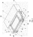
- a piece of furniture according to the invention is disclosed, which is generally indicated with reference numeral (M).
- the piece of furniture (M) comprises a frame (L) comprising a top (P), two sides (S), a bottom (N) and a compartment (V) defined by the top (P) in upper position, by the sides (S) in lateral position and by the bottom (N) in lower position.
- the piece of furniture (M) comprises a front lid (C) suitable for closing the compartment (V).
- the piece of furniture (M) comprises a pull-out unit (100) that is fixed to the frame (L) and is suitable for increasing the surface of the piece of furniture (M).
- the pull-out unit (100) comprises a worktop (1) suitable for acting as surface.
- the worktop (1) comprises a plurality of extensions (10). Said extensions (10) can be in an operating position, wherein the extensions (10) are outside the compartment (V) of the frame (L) in coplanar position, in order to act as surface, and in an idle position, wherein the extensions (10) are overlapped one on top of the other.
- the pull-out unit (100) comprises two guides (2) in parallel position.
- Each guide (2) comprises a first section (20) fixed to the frame (L), and a second section (21) that slides with respect to said first section (20), so that the sections (20, 21) can be in a contracted position, as shown in Fig. 1 , and in an extended position, as shown in Figs. 4 and 5 .
- said sections (20, 21) are disposed inside the compartment (V) of the frame (L).
- the second section (21) comes out of the compartment (V) of the frame (L).
- each guide (2) comprises an internal surface (21a) directed towards the other guide (2), and an external surface (21b) opposed to the internal surface (21a).
- the guides (2) comprise a plurality of intermediate sections (22), disposed between the first section (20) and the second section (21).
- the intermediate sections (22) are mounted with possibility of sliding mutually or with respect to the first section (20).
- the extension (10) in proximal position to the frame (L) is joined to one of the intermediate sections of each guide (2).
- the extensions (10) in idle position are disposed above said intermediate section. In view of the above, when said section comes out of the compartment (V) of the frame (L), also the extensions in idle position come out of the compartment (V).
- the extension (10) in proximal position to the frame (L) is joined to the third intermediate section of each guide (2).
- the pull-out unit (100) comprises two legs (3), which are disposed in parallel position and are connected to the second section (21) of the guide (2).
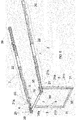
- Each leg (3) has an "L"-shape and comprises a first bar (30) having a longitudinal axis (X) and a second bar (31) having a longitudinal axis (Y), perpendicular to the longitudinal axis (X) of the first bar (30).
- the second bar (31) is telescopic and comprises an external tubular body (31a), and an internal body (31b), which are advantageously provided with a square section.
- the internal body (31b) is mounted with possibility of telescopically sliding inside the external tubular body (31a), in such a way to be in an extracted position, as shown in Figs. 4 and 5 , and in a retracted position.
- the pull-out unit (100) comprises stop means (8), as shown in Figs. 3 , 4 and 5 , to stop the sliding of the internal body (31b) inside the external tubular body (31a) when the internal body (31b) reaches its extracted position, so that the leg (3) acts as a firm support for the worktop (1).
- the external tubular body (31a) comprises a hole in transverse position with respect to the longitudinal axis (Y) of the second bar (31) of the leg (3)
- the internal body (31b) comprises a housing in transverse position with respect to the longitudinal axis (Y) of the second bar (31) of the leg (3).
- the stop means (8) comprise a plug (80) mounted inside the housing of the internal body (31b).
- the stop means (8) also comprise an elastic member (not shown in the enclosed figures) that pushes the plug (80) outside the housing of the internal body (31b).
- the plug (80) is inserted in the transverse hole of the external tubular body (31a) when the housing of the internal body (31b) is aligned with the transverse hole of the external tubular body (31a), i.e. when the internal body (31b) is in extracted position.
- the second bar (31) of each leg (3) comprises a first end, which is suitable for being in contact with the ground, and a second end, which is connected to the first bar (30) of the leg (3).
- the pull-out unit (100) comprises a transverse bar (35) connected to the first end of the second bar (31) of each leg (3) in order to join the two legs (3).
- the two legs (3) and the transverse bar (35) form a "U", as shown in Figs. 1 to 5 .
- the transverse bar (35) is suitable for being disposed in horizontal position in contact with the ground.
- the transverse bar (35) comprises two adjustable feet, which are suitable for being in contact with the ground.
- the first bar (30) of each guide (3) comprises an internal surface (30a) directed towards the internal surface (30a) of the first bar (30) of the other leg (3), and an external surface (30b) opposed to the internal surface (30a).
- the external surface (30b) of the first bar (30) of each leg (3) is suitable for being disposed in adjacent position to the internal surface (21a) of the second section (21) of the guide (2).
- the first bar (30) of each leg (3) comprises a free end that is connected to the second section (21) of the guide (2), a peg (32) that protrudes transversally from the internal surface (30a) of the first bar (30), and a hole (33), as shown in Fig. 7 , in transverse position with respect to the longitudinal axis (X) of the first bar (30).
- the pull-out unit (100) comprises connection means (7) connected to the leg (3) and to the second section (21) of the guide (2) to revolvingly connect the leg (3) with respect to the second section (21), so that the leg (3) make a rotation of at least 250°, more precisely 270°, rotating between an operating position, as shown in Figs. 3 , 4 and 5 , wherein the second bar (31) of the leg (3) is perpendicular to the second section (21) of the guide (2), and an idle position, as shown in Figs. 1 and 2 , wherein the second bar (31) of the leg (3) is horizontal and parallel to the worktop (1) and the first bar (30) is vertical and perpendicular to the extensions (10) of the worktop (1).
- the length of the first bar (30) is slightly higher than the height of the extensions (10) of the worktop (1) in idle position, so that when the legs (3) are in idle position, the second bar (31) of the leg (3) is disposed in horizontal position above the worktop (1), when the extensions (10) are in idle position, i.e. overlapped one on top of the other.
- the pull-out unit (G) comprises mechanical stops that block the second bar (31) of the leg (3) in horizontal position, without said second bar (31) being in contact with the extensions (10) of the worktop (1), thus allowing for disposing the legs (3) in idle position even if the guides (2) are still in extracted position.
- the legs (3) go from the operating position to the idle position, and vice versa, when the guides (2) are in extended position, the extensions (10) of the worktop (1) are in idle position and the second bar (31) of the legs (3) is in retracted position.
- the pull-out unit (G) comprises a crossbar (70) with length equal to the distance between the two guides (2), in such a way that said crossbar (70) is connected to both guides (2) and to both legs (3). It must be noted that the crossbar (70) is fixed and the legs (3) rotate around said crossbar (70).
- the legs (3) can be easily and rapidly moved from the operating position to the idle position and vice versa, without requiring a great physical effort and without causing any problem.
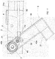
- the pull-out unit (100) also comprises two locking devices (4) to lock the leg (3) in operating position. Both locking devices (4) are connected to the crossbar (70) in such a way to move simultaneously. Each locking device (4) is connected to one of the two legs (3).
- each locking device (4) comprises a lever (40) that is hinged to the leg (3) in such a way to rotate with respect to the crossbar (70) along an axis that coincides with the axis of rotation of the leg (3).
- the lever (40) comprises a housing (40a) that is opened laterally and is defined by a curvilinear edge.
- the housing (40a) is intended to receive the peg (32) of the first bar (30) of the leg (3) during the rotation of the leg (3).
- the lever (40) comprises an opening (40b) in coaxial position to the hole (33) of the first bar (30) of the leg (3) when the leg (3) is in operating position.
- each locking device (4) comprises a cam-tappet assembly (50,51) comprising a cam (50) joined to the second section (21) of the guide (2).
- the cam (50) is disposed on the internal surface (21 a) of each second section (21), in such a way to be directed towards the first bar (30) of the leg (3).
- the cam-tappet assembly (50,51) comprises a tappet comprising a button (51) disposed inside the hole (33) of the first bar (30) of the leg (3), and a retention element (52) connected to the button (51) to push the button (51) towards the cam (50).
- the button (51) comprises a striker (51a) suitable for being disposed in the opening (40b) of the lever (40), and a head (51b) that cooperates with the cam (50) to push said striker (51a) in the opening (40b) of the lever (40).
- the pull-out unit (100) also comprises a shelf (M1) fixed above the second section (21) of one of the two guides (2).
- the shelf (M1) is configured in such a way to stop the legs (3) in operating position and prevent an additional rotation of the legs (3) above the guides (2).
- the pull-out unit (100) advantageously comprises dampening means (6) comprising a linear actuator (60) for each leg (3), connected to the second section (21) of the guide (2) and to the lever (40).
- the linear actuator (60) is a jack comprising a cylinder (61) that is provided with a free end hinged to the second bar (21) of the guide (2) in a first hinging point (P1), and a stem (62) that slides in the cylinder (61) and comprises a free end hinged to the lever (40) of the locking device (4) in a second hinging point (P2).
- the operating principle of the linear actuator (60) is such that, after drawing a straight line passing through the first hinging point (P1) and through the axis of rotation of the lever (40), three positions can be configured:
- the linear actuator (60) pushes the first bar (30) of the leg (3) upwards, stopping against the shelf (M1), in such a way to additionally lock the legs (3) in operating position, as shown in Fig. 4 .
- the second hinging point (P2) rotates, being disposed under the first hinging point (P1), in such a way that the linear actuator (60) pushes the first bar (30) of the leg (3) downwards, favoring the rotation of the leg (3) towards the idle position, as shown in Fig. 11 .
- the second hinging point (P2) rotates, being disposed above the first hinging point (P1) in the last portion of rotation, in such a way that the linear actuator (60) pushes the first bar (30) of the leg (3) upwards, preventing it from rotating by gravity towards the idle position.
- a force must be applied on the guides (2) towards the exterior of the compartment (V) of the piece of furniture (M), in such a way that said guides (2) go from the contracted position to the extended position, as shown in Fig. 2 .
- the crossbar (70) can be pulled towards the exterior of the compartment (V) of the piece of furniture (M), in such a way to permit the simultaneous extension of both guides (2).
- the legs (3) are folded over from the idle position to the operating position. It is simply necessary to rotate the legs (3) manually for a first portion of said rotation, because the dampening means (6) accompany the leg in the last portion of rotation.
- the first bar (30) of the legs (3) is disposed in vertical position under the guides (2), whereas the second bar (31) of the leg (3) is disposed in horizontal position, protruding from the guide (2).
- the internal body (31b) of the second bar (31) of the legs (3) slides inside the external tubular body (31a), so that the plug (80) is inserted in the transverse hole of the external tubular body (31a), disposing the leg (31) in extracted position.
- the peg (32) of the first bar (30) intercepts the lever (40) and is disposed inside the housing (40a) of the lever (40).
- the opening (40b) of the lever (4) is aligned with the transverse hole (33) of the first bar (30) of the leg (3).
- the leg (3) drives the lever (40) into rotation.
- the head (51b) of the button (51) cooperates with the cam (50), in such a way to push the striker (51a) in the opening (40b) of the lever (4) and to fix the lever (40) to the leg (3), so that, after reaching its operating position, the leg (3) does not make a rotation in opposite direction, rotating towards the idle position.
- the linear actuator (60) is driven into rotation by the lever (40).
- the linear actuator (60) accompanies and locks the legs (3) in operating position.
- the shelf (M1) stops the rotation of the legs (3), when the leg (3) has made a rotation of 270° from the idle position to the operating position.
- the legs (3) are in contact with the ground.
- the extensions (10) of the worktop (1) are disposed in operating position, above the guides (2).
- the extensions In order to replace the pull-out unit (100) inside the compartment (V) of the frame (L), the extensions must be disposed in idle position.
- the legs (3) are folded over from the operating position to the idle position. It is simply necessary to gently push the legs (3) in order to rotate said legs (3) by approximately 90° from the operating position to the idle position because the dampening means (6) accompany the legs (3) in said portion of rotation. It must be noted that such a push can be given manually or using one of the two feet, so that the user can make such an operation while standing straight.
- the lever (40) rotates.
- the linear actuator (60) is driven into rotation by the lever (40).
- the second hinging point (P2) is disposed under the first hinging point (P1). Consequently, the linear actuator (60) accompanies the legs (3) towards the idle position.
- the linear actuator (60) accompanies the legs (3) until when the first bar (30) is disposed in vertical position under the guides (2) and the second bar (31) is disposed in horizontal position.
- the head (51b) of the button (51) slides on the cam (50).
- the retention element (52) pushes the striker (51a) inside the transverse hole (33) of the first bar (30) of the lever (3).
- the leg (3) is moved manually to its idle position. Such a manual movement is very comfortable for the user because in view of the fact that, because of the action of the linear actuator (60), the leg (3) is brought from the linear actuator (60) to such a height that the user does not need to bend down or make a great physical effort to take the leg (3) and move it to its idle position.
- the guides (2) can be brought to the retracted position, as shown in Fig.1 .
Landscapes
- Legs For Furniture In General (AREA)
- Table Devices Or Equipment (AREA)
- Professional, Industrial, Or Sporting Protective Garments (AREA)
- Walking Sticks, Umbrellas, And Fans (AREA)
Applications Claiming Priority (1)
| Application Number | Priority Date | Filing Date | Title |
|---|---|---|---|
| IT102016000103184A IT201600103184A1 (it) | 2016-10-13 | 2016-10-13 | Mobile con gruppo estraibile avente una gamba ribaltabile. |
Publications (2)
| Publication Number | Publication Date |
|---|---|
| EP3308672A1 true EP3308672A1 (fr) | 2018-04-18 |
| EP3308672B1 EP3308672B1 (fr) | 2019-04-24 |
Family
ID=58159357
Family Applications (1)
| Application Number | Title | Priority Date | Filing Date |
|---|---|---|---|
| EP17195556.0A Not-in-force EP3308672B1 (fr) | 2016-10-13 | 2017-10-09 | Meuble avec une unite de tirage comprenant un pied pliable |
Country Status (2)
| Country | Link |
|---|---|
| EP (1) | EP3308672B1 (fr) |
| IT (1) | IT201600103184A1 (fr) |
Citations (3)
| Publication number | Priority date | Publication date | Assignee | Title |
|---|---|---|---|---|
| US2672384A (en) * | 1950-02-01 | 1954-03-16 | Russell T Richards | Fold-away cabinet table |
| FR1435131A (fr) * | 1965-03-03 | 1966-04-15 | Boulnois Et Cie Soc | Porte <abattante> avec pieds escamotables |
| EP1444922A2 (fr) * | 2003-01-08 | 2004-08-11 | Nicholas King | Surface de travail pliable |
-
2016
- 2016-10-13 IT IT102016000103184A patent/IT201600103184A1/it unknown
-
2017
- 2017-10-09 EP EP17195556.0A patent/EP3308672B1/fr not_active Not-in-force
Patent Citations (3)
| Publication number | Priority date | Publication date | Assignee | Title |
|---|---|---|---|---|
| US2672384A (en) * | 1950-02-01 | 1954-03-16 | Russell T Richards | Fold-away cabinet table |
| FR1435131A (fr) * | 1965-03-03 | 1966-04-15 | Boulnois Et Cie Soc | Porte <abattante> avec pieds escamotables |
| EP1444922A2 (fr) * | 2003-01-08 | 2004-08-11 | Nicholas King | Surface de travail pliable |
Also Published As
| Publication number | Publication date |
|---|---|
| IT201600103184A1 (it) | 2018-04-13 |
| EP3308672B1 (fr) | 2019-04-24 |
Similar Documents
| Publication | Publication Date | Title |
|---|---|---|
| US10806247B1 (en) | Slider, frame and table having same | |
| US4144822A (en) | Folding leg mechanism | |
| EP2413748B1 (fr) | Chaise haute équipée de pieds pliants | |
| US6547321B2 (en) | Folding chair | |
| US20080034506A1 (en) | Changing table for playard | |
| US7614097B1 (en) | Structure of a foldable mechanism of a baby mesh bed | |
| US20190090626A1 (en) | Folding table | |
| US8007378B2 (en) | Ping-pong table/locking with an indexing finger | |
| US9382730B1 (en) | Locking device for two-way travel drawer | |
| KR20220058539A (ko) | 접이식 높이 조절 테이블 | |
| US6609615B2 (en) | Supporting frame for a golf bag | |
| CN108348069B (zh) | 用于可运动的家具部件的拉入设备 | |
| CN101150972B (zh) | 用于在家具体内可移动地设置的家具件的伸缩式引导装置 | |
| KR101272310B1 (ko) | 테이블 상판의 각도조절장치 | |
| US9675169B1 (en) | Extendable table | |
| EP3308672B1 (fr) | Meuble avec une unite de tirage comprenant un pied pliable | |
| JP5905396B2 (ja) | ロック可能な引出ガイド | |
| CN103653891B (zh) | 滑轨总成及自我启闭式的滑轨总成 | |
| WO2010114458A1 (fr) | Chaise haute équipée de pieds pliants | |
| JP5970382B2 (ja) | 建具および突出維持部品 | |
| KR20110006306U (ko) | 다리의 폴딩 및 자동 언폴딩이 가능한 테이블 | |
| CN103767396A (zh) | 一种折叠高餐椅 | |
| EP3944787A1 (fr) | Table extensible | |
| EP1127516A1 (fr) | Chaise pliable | |
| CN209687107U (zh) | 自动插销装置 |
Legal Events
| Date | Code | Title | Description |
|---|---|---|---|
| PUAI | Public reference made under article 153(3) epc to a published international application that has entered the european phase |
Free format text: ORIGINAL CODE: 0009012 |
|
| STAA | Information on the status of an ep patent application or granted ep patent |
Free format text: STATUS: THE APPLICATION HAS BEEN PUBLISHED |
|
| AK | Designated contracting states |
Kind code of ref document: A1 Designated state(s): AL AT BE BG CH CY CZ DE DK EE ES FI FR GB GR HR HU IE IS IT LI LT LU LV MC MK MT NL NO PL PT RO RS SE SI SK SM TR |
|
| AX | Request for extension of the european patent |
Extension state: BA ME |
|
| STAA | Information on the status of an ep patent application or granted ep patent |
Free format text: STATUS: REQUEST FOR EXAMINATION WAS MADE |
|
| 17P | Request for examination filed |
Effective date: 20181009 |
|
| RBV | Designated contracting states (corrected) |
Designated state(s): AL AT BE BG CH CY CZ DE DK EE ES FI FR GB GR HR HU IE IS IT LI LT LU LV MC MK MT NL NO PL PT RO RS SE SI SK SM TR |
|
| GRAP | Despatch of communication of intention to grant a patent |
Free format text: ORIGINAL CODE: EPIDOSNIGR1 |
|
| STAA | Information on the status of an ep patent application or granted ep patent |
Free format text: STATUS: GRANT OF PATENT IS INTENDED |
|
| INTG | Intention to grant announced |
Effective date: 20181213 |
|
| GRAS | Grant fee paid |
Free format text: ORIGINAL CODE: EPIDOSNIGR3 |
|
| GRAA | (expected) grant |
Free format text: ORIGINAL CODE: 0009210 |
|
| STAA | Information on the status of an ep patent application or granted ep patent |
Free format text: STATUS: THE PATENT HAS BEEN GRANTED |
|
| AK | Designated contracting states |
Kind code of ref document: B1 Designated state(s): AL AT BE BG CH CY CZ DE DK EE ES FI FR GB GR HR HU IE IS IT LI LT LU LV MC MK MT NL NO PL PT RO RS SE SI SK SM TR |
|
| REG | Reference to a national code |
Ref country code: GB Ref legal event code: FG4D |
|
| REG | Reference to a national code |
Ref country code: CH Ref legal event code: EP |
|
| REG | Reference to a national code |
Ref country code: AT Ref legal event code: REF Ref document number: 1123084 Country of ref document: AT Kind code of ref document: T Effective date: 20190515 Ref country code: IE Ref legal event code: FG4D |
|
| REG | Reference to a national code |
Ref country code: DE Ref legal event code: R096 Ref document number: 602017003499 Country of ref document: DE |
|
| REG | Reference to a national code |
Ref country code: NL Ref legal event code: MP Effective date: 20190424 |
|
| REG | Reference to a national code |
Ref country code: LT Ref legal event code: MG4D |
|
| PG25 | Lapsed in a contracting state [announced via postgrant information from national office to epo] |
Ref country code: NL Free format text: LAPSE BECAUSE OF FAILURE TO SUBMIT A TRANSLATION OF THE DESCRIPTION OR TO PAY THE FEE WITHIN THE PRESCRIBED TIME-LIMIT Effective date: 20190424 |
|
| PG25 | Lapsed in a contracting state [announced via postgrant information from national office to epo] |
Ref country code: LT Free format text: LAPSE BECAUSE OF FAILURE TO SUBMIT A TRANSLATION OF THE DESCRIPTION OR TO PAY THE FEE WITHIN THE PRESCRIBED TIME-LIMIT Effective date: 20190424 Ref country code: FI Free format text: LAPSE BECAUSE OF FAILURE TO SUBMIT A TRANSLATION OF THE DESCRIPTION OR TO PAY THE FEE WITHIN THE PRESCRIBED TIME-LIMIT Effective date: 20190424 Ref country code: AL Free format text: LAPSE BECAUSE OF FAILURE TO SUBMIT A TRANSLATION OF THE DESCRIPTION OR TO PAY THE FEE WITHIN THE PRESCRIBED TIME-LIMIT Effective date: 20190424 Ref country code: ES Free format text: LAPSE BECAUSE OF FAILURE TO SUBMIT A TRANSLATION OF THE DESCRIPTION OR TO PAY THE FEE WITHIN THE PRESCRIBED TIME-LIMIT Effective date: 20190424 Ref country code: NO Free format text: LAPSE BECAUSE OF FAILURE TO SUBMIT A TRANSLATION OF THE DESCRIPTION OR TO PAY THE FEE WITHIN THE PRESCRIBED TIME-LIMIT Effective date: 20190724 Ref country code: SE Free format text: LAPSE BECAUSE OF FAILURE TO SUBMIT A TRANSLATION OF THE DESCRIPTION OR TO PAY THE FEE WITHIN THE PRESCRIBED TIME-LIMIT Effective date: 20190424 Ref country code: PT Free format text: LAPSE BECAUSE OF FAILURE TO SUBMIT A TRANSLATION OF THE DESCRIPTION OR TO PAY THE FEE WITHIN THE PRESCRIBED TIME-LIMIT Effective date: 20190824 Ref country code: HR Free format text: LAPSE BECAUSE OF FAILURE TO SUBMIT A TRANSLATION OF THE DESCRIPTION OR TO PAY THE FEE WITHIN THE PRESCRIBED TIME-LIMIT Effective date: 20190424 |
|
| PG25 | Lapsed in a contracting state [announced via postgrant information from national office to epo] |
Ref country code: BG Free format text: LAPSE BECAUSE OF FAILURE TO SUBMIT A TRANSLATION OF THE DESCRIPTION OR TO PAY THE FEE WITHIN THE PRESCRIBED TIME-LIMIT Effective date: 20190724 Ref country code: GR Free format text: LAPSE BECAUSE OF FAILURE TO SUBMIT A TRANSLATION OF THE DESCRIPTION OR TO PAY THE FEE WITHIN THE PRESCRIBED TIME-LIMIT Effective date: 20190725 Ref country code: PL Free format text: LAPSE BECAUSE OF FAILURE TO SUBMIT A TRANSLATION OF THE DESCRIPTION OR TO PAY THE FEE WITHIN THE PRESCRIBED TIME-LIMIT Effective date: 20190424 Ref country code: LV Free format text: LAPSE BECAUSE OF FAILURE TO SUBMIT A TRANSLATION OF THE DESCRIPTION OR TO PAY THE FEE WITHIN THE PRESCRIBED TIME-LIMIT Effective date: 20190424 Ref country code: RS Free format text: LAPSE BECAUSE OF FAILURE TO SUBMIT A TRANSLATION OF THE DESCRIPTION OR TO PAY THE FEE WITHIN THE PRESCRIBED TIME-LIMIT Effective date: 20190424 |
|
| PGFP | Annual fee paid to national office [announced via postgrant information from national office to epo] |
Ref country code: LU Payment date: 20191025 Year of fee payment: 3 |
|
| REG | Reference to a national code |
Ref country code: AT Ref legal event code: MK05 Ref document number: 1123084 Country of ref document: AT Kind code of ref document: T Effective date: 20190424 |
|
| PG25 | Lapsed in a contracting state [announced via postgrant information from national office to epo] |
Ref country code: IS Free format text: LAPSE BECAUSE OF FAILURE TO SUBMIT A TRANSLATION OF THE DESCRIPTION OR TO PAY THE FEE WITHIN THE PRESCRIBED TIME-LIMIT Effective date: 20190824 |
|
| REG | Reference to a national code |
Ref country code: DE Ref legal event code: R097 Ref document number: 602017003499 Country of ref document: DE |
|
| PG25 | Lapsed in a contracting state [announced via postgrant information from national office to epo] |
Ref country code: EE Free format text: LAPSE BECAUSE OF FAILURE TO SUBMIT A TRANSLATION OF THE DESCRIPTION OR TO PAY THE FEE WITHIN THE PRESCRIBED TIME-LIMIT Effective date: 20190424 Ref country code: RO Free format text: LAPSE BECAUSE OF FAILURE TO SUBMIT A TRANSLATION OF THE DESCRIPTION OR TO PAY THE FEE WITHIN THE PRESCRIBED TIME-LIMIT Effective date: 20190424 Ref country code: AT Free format text: LAPSE BECAUSE OF FAILURE TO SUBMIT A TRANSLATION OF THE DESCRIPTION OR TO PAY THE FEE WITHIN THE PRESCRIBED TIME-LIMIT Effective date: 20190424 Ref country code: CZ Free format text: LAPSE BECAUSE OF FAILURE TO SUBMIT A TRANSLATION OF THE DESCRIPTION OR TO PAY THE FEE WITHIN THE PRESCRIBED TIME-LIMIT Effective date: 20190424 Ref country code: SK Free format text: LAPSE BECAUSE OF FAILURE TO SUBMIT A TRANSLATION OF THE DESCRIPTION OR TO PAY THE FEE WITHIN THE PRESCRIBED TIME-LIMIT Effective date: 20190424 Ref country code: DK Free format text: LAPSE BECAUSE OF FAILURE TO SUBMIT A TRANSLATION OF THE DESCRIPTION OR TO PAY THE FEE WITHIN THE PRESCRIBED TIME-LIMIT Effective date: 20190424 |
|
| PGFP | Annual fee paid to national office [announced via postgrant information from national office to epo] |
Ref country code: IE Payment date: 20191021 Year of fee payment: 3 |
|
| PG25 | Lapsed in a contracting state [announced via postgrant information from national office to epo] |
Ref country code: SM Free format text: LAPSE BECAUSE OF FAILURE TO SUBMIT A TRANSLATION OF THE DESCRIPTION OR TO PAY THE FEE WITHIN THE PRESCRIBED TIME-LIMIT Effective date: 20190424 Ref country code: IT Free format text: LAPSE BECAUSE OF FAILURE TO SUBMIT A TRANSLATION OF THE DESCRIPTION OR TO PAY THE FEE WITHIN THE PRESCRIBED TIME-LIMIT Effective date: 20190424 |
|
| PGFP | Annual fee paid to national office [announced via postgrant information from national office to epo] |
Ref country code: BE Payment date: 20191025 Year of fee payment: 3 |
|
| PLBE | No opposition filed within time limit |
Free format text: ORIGINAL CODE: 0009261 |
|
| STAA | Information on the status of an ep patent application or granted ep patent |
Free format text: STATUS: NO OPPOSITION FILED WITHIN TIME LIMIT |
|
| PG25 | Lapsed in a contracting state [announced via postgrant information from national office to epo] |
Ref country code: TR Free format text: LAPSE BECAUSE OF FAILURE TO SUBMIT A TRANSLATION OF THE DESCRIPTION OR TO PAY THE FEE WITHIN THE PRESCRIBED TIME-LIMIT Effective date: 20190424 |
|
| 26N | No opposition filed |
Effective date: 20200127 |
|
| PG25 | Lapsed in a contracting state [announced via postgrant information from national office to epo] |
Ref country code: MC Free format text: LAPSE BECAUSE OF FAILURE TO SUBMIT A TRANSLATION OF THE DESCRIPTION OR TO PAY THE FEE WITHIN THE PRESCRIBED TIME-LIMIT Effective date: 20190424 Ref country code: SI Free format text: LAPSE BECAUSE OF FAILURE TO SUBMIT A TRANSLATION OF THE DESCRIPTION OR TO PAY THE FEE WITHIN THE PRESCRIBED TIME-LIMIT Effective date: 20190424 |
|
| PG25 | Lapsed in a contracting state [announced via postgrant information from national office to epo] |
Ref country code: CY Free format text: LAPSE BECAUSE OF FAILURE TO SUBMIT A TRANSLATION OF THE DESCRIPTION OR TO PAY THE FEE WITHIN THE PRESCRIBED TIME-LIMIT Effective date: 20190424 |
|
| REG | Reference to a national code |
Ref country code: CH Ref legal event code: PL |
|
| PG25 | Lapsed in a contracting state [announced via postgrant information from national office to epo] |
Ref country code: LU Free format text: LAPSE BECAUSE OF NON-PAYMENT OF DUE FEES Effective date: 20201009 Ref country code: CH Free format text: LAPSE BECAUSE OF FAILURE TO SUBMIT A TRANSLATION OF THE DESCRIPTION OR TO PAY THE FEE WITHIN THE PRESCRIBED TIME-LIMIT Effective date: 20201031 Ref country code: LI Free format text: LAPSE BECAUSE OF FAILURE TO SUBMIT A TRANSLATION OF THE DESCRIPTION OR TO PAY THE FEE WITHIN THE PRESCRIBED TIME-LIMIT Effective date: 20201031 |
|
| REG | Reference to a national code |
Ref country code: BE Ref legal event code: MM Effective date: 20201031 |
|
| PG25 | Lapsed in a contracting state [announced via postgrant information from national office to epo] |
Ref country code: HU Free format text: LAPSE BECAUSE OF FAILURE TO SUBMIT A TRANSLATION OF THE DESCRIPTION OR TO PAY THE FEE WITHIN THE PRESCRIBED TIME-LIMIT; INVALID AB INITIO Effective date: 20171009 Ref country code: MT Free format text: LAPSE BECAUSE OF FAILURE TO SUBMIT A TRANSLATION OF THE DESCRIPTION OR TO PAY THE FEE WITHIN THE PRESCRIBED TIME-LIMIT Effective date: 20190424 |
|
| PG25 | Lapsed in a contracting state [announced via postgrant information from national office to epo] |
Ref country code: BE Free format text: LAPSE BECAUSE OF NON-PAYMENT OF DUE FEES Effective date: 20201031 |
|
| PG25 | Lapsed in a contracting state [announced via postgrant information from national office to epo] |
Ref country code: IE Free format text: LAPSE BECAUSE OF NON-PAYMENT OF DUE FEES Effective date: 20201009 |
|
| PGFP | Annual fee paid to national office [announced via postgrant information from national office to epo] |
Ref country code: DE Payment date: 20211027 Year of fee payment: 5 Ref country code: GB Payment date: 20211026 Year of fee payment: 5 |
|
| PGFP | Annual fee paid to national office [announced via postgrant information from national office to epo] |
Ref country code: FR Payment date: 20211027 Year of fee payment: 5 |
|
| PG25 | Lapsed in a contracting state [announced via postgrant information from national office to epo] |
Ref country code: MK Free format text: LAPSE BECAUSE OF FAILURE TO SUBMIT A TRANSLATION OF THE DESCRIPTION OR TO PAY THE FEE WITHIN THE PRESCRIBED TIME-LIMIT Effective date: 20190424 |
|
| REG | Reference to a national code |
Ref country code: DE Ref legal event code: R119 Ref document number: 602017003499 Country of ref document: DE |
|
| GBPC | Gb: european patent ceased through non-payment of renewal fee |
Effective date: 20221009 |
|
| PG25 | Lapsed in a contracting state [announced via postgrant information from national office to epo] |
Ref country code: FR Free format text: LAPSE BECAUSE OF NON-PAYMENT OF DUE FEES Effective date: 20221031 Ref country code: DE Free format text: LAPSE BECAUSE OF NON-PAYMENT OF DUE FEES Effective date: 20230503 |
|
| PG25 | Lapsed in a contracting state [announced via postgrant information from national office to epo] |
Ref country code: GB Free format text: LAPSE BECAUSE OF NON-PAYMENT OF DUE FEES Effective date: 20221009 |