EP3308676A1 - Dispositif de support, ensemble support et dispositif formant poste de travail debout - Google Patents
Dispositif de support, ensemble support et dispositif formant poste de travail debout Download PDFInfo
- Publication number
- EP3308676A1 EP3308676A1 EP17186425.9A EP17186425A EP3308676A1 EP 3308676 A1 EP3308676 A1 EP 3308676A1 EP 17186425 A EP17186425 A EP 17186425A EP 3308676 A1 EP3308676 A1 EP 3308676A1
- Authority
- EP
- European Patent Office
- Prior art keywords
- standing
- support
- anchoring
- person
- bar table
- Prior art date
- Legal status (The legal status is an assumption and is not a legal conclusion. Google has not performed a legal analysis and makes no representation as to the accuracy of the status listed.)
- Withdrawn
Links
Images




Classifications
-
- A—HUMAN NECESSITIES
- A47—FURNITURE; DOMESTIC ARTICLES OR APPLIANCES; COFFEE MILLS; SPICE MILLS; SUCTION CLEANERS IN GENERAL
- A47B—TABLES; DESKS; OFFICE FURNITURE; CABINETS; DRAWERS; GENERAL DETAILS OF FURNITURE
- A47B19/00—Reading-desks; Lecterns; Pulpits, i.e. free-standing
- A47B19/10—Reading-desks; Lecterns; Pulpits, i.e. free-standing characterised by association with auxiliary devices, e.g. paper clamps, line indicators
-
- A—HUMAN NECESSITIES
- A47—FURNITURE; DOMESTIC ARTICLES OR APPLIANCES; COFFEE MILLS; SPICE MILLS; SUCTION CLEANERS IN GENERAL
- A47C—CHAIRS; SOFAS; BEDS
- A47C9/00—Stools for specified purposes
- A47C9/02—Office stools; Workshop stools
- A47C9/022—Office stools; Workshop stools movably mounted on a working-table or the like
-
- A—HUMAN NECESSITIES
- A47—FURNITURE; DOMESTIC ARTICLES OR APPLIANCES; COFFEE MILLS; SPICE MILLS; SUCTION CLEANERS IN GENERAL
- A47C—CHAIRS; SOFAS; BEDS
- A47C9/00—Stools for specified purposes
- A47C9/02—Office stools; Workshop stools
- A47C9/025—Stools for standing or leaning against, e.g. in a semi-standing or half-seated position
-
- A—HUMAN NECESSITIES
- A47—FURNITURE; DOMESTIC ARTICLES OR APPLIANCES; COFFEE MILLS; SPICE MILLS; SUCTION CLEANERS IN GENERAL
- A47B—TABLES; DESKS; OFFICE FURNITURE; CABINETS; DRAWERS; GENERAL DETAILS OF FURNITURE
- A47B2200/00—General construction of tables or desks
- A47B2200/0084—Accessories for tables or desks
- A47B2200/0085—Supplementary support fixed on the edge of a desk or table
Definitions
- the present invention relates to a support device for a standing workstation arrangement.
- the present invention further relates to a support assembly with such a support device and a standing workstation arrangement.
- standing desk and standing aids There are combinations of standing desk and standing aids.
- the document describes DE 298 18 890 U 1 is a standing workstation arrangement in which a standing aid is connected to a standing desk via a floor panel.
- the present invention has the object to provide an improved support device for a standing workstation arrangement and an improved standing workstation arrangement.
- this object is achieved by a support device having the features of patent claim 1 and / or a support arrangement having the features of patent claim 7 and / or stand-up workstation arrangement having the features of patent claim 8.
- the idea underlying the present invention is to provide a standing table instead of a standing desk and to anchor a supporting device instead of a base plate in the area of a table top of the bar table or to make it anchorable.
- a large work surface which is suitable for example for office work, such as PC work, paperwork, paperwork or the like.
- a standing workstation arrangement when not in use, advantageously saves space.
- a bar table usually has not only a larger work surface but also a greater depth than a standing desk.
- the standing table has a standing depth of at least 70% of the working surface depth. Greater depths of depth, in particular a depth corresponding to the depth of the working surface, are possible.
- a lever action transmitted to the area of the tabletop by the support device can be supported by the larger depth of a standing table with a larger lever.
- a standing desk according to the invention can be ensured that when attaching the support device in the area of the table top of the bar table does not tilt without the need for a space requirement of the table top floor plate or the like is necessary.
- An attachment in the region of the tabletop is in particular realized with an anchoring device which is not necessarily provided directly on the tabletop, but may also be provided on a tabletop support carrying a base of the bar table near the table top and / or approximately at the height of the table top ,
- the support device acts in particular as a standing aid and can be used for partial weight support or even only to relieve the lumbar spine or for easy leaning a standing person.
- An embodiment of the anchoring section for anchoring to an anchoring device arranged in the region of a table top of a bar table and a support section for supporting a standing person in a direction away from the anchoring section in the buttocks and / or lower back region presupposes that an appropriate orientation and force transmission of the anchored Anchoring portion and a person standing supportive supporting portion is made possible to the desired support effect in for a Standing workstation suitable ergonomic way to provide.
- the fastenability of an anchoring device to a bar table in the area of the table top is such that a person standing on the bar table can rest in the buttock and / or lower back area in the anchoring device anchored support device in a direction away from the bar table, that adapted to a table top fastening technology and a maximum strength of a standing person sufficiently strong, that is in particular designed for the body weight of the 95th percentile man, particularly durable, connection with a table top is possible.
- the anchoring section has a suspension device and a closure device for securing the suspension device in an anchoring device.
- the support device is securely anchored in an anchoring device.
- it is a releasable closure device, so that the support device is releasably anchored.
- the support portion is formed as a loop, wherein an anchoring portion is provided at both ends of the loop. Accordingly, the loop always has a course which ends with the two anchoring sections.
- it is a flexible loop, which in particular has a belt. It is therefore advantageous form variable and yet has a high tensile strength at low elongation.
- the loop may also be formed of an elastic material.
- a certain mobility ie, for example, a rocker or a dynamic change of the standing position allow.
- the support section has a power transmission area and a backrest area.
- the backrest area is designed to receive leaning forces of the standing person, while the power transmission area is designed to transmit the leaning forces to the anchoring section.
- the backrest area can be ergonomically shaped and possibly upholstered while the power transmission area can be designed purely for the desired power transmission.
- the force transmission region and the backrest region can be two elements which are connected to one another, run into one another in a form-fitting manner or are suspended in one another.
- a one-piece design is conceivable, in which case a different shape of the areas is provided, which is designed and adapted to the respective function.
- the backrest region has a first elasticity, while the power transmission region has a second elasticity different therefrom.
- the individual properties of the areas can be set particularly advantageous individually. For example, it may have a greater elasticity backrest area to provide so advantageously a good Anmulation to the person standing, while the power transmission section has a low elasticity to transmit the forces as directly as possible to the anchoring portion and so to ensure a particularly secure support.
- the anchoring portion has a third elasticity, wherein the third elasticity is smaller than the first elasticity and the second elasticity.
- the anchoring portion is a particularly stiff portion of very low elasticity and high strength. In this way a secure anchoring is guaranteed.
- the second elasticity is greater than the first elasticity.
- the backrest area is particularly dimensionally stable and so the person standing conveys a good ergonomic feedback
- the power transmission section may have a certain elasticity, so as to allow a mobility or a dynamic standing or optionally a rocking person.
- the backrest region has a lower buttock support area and an upper lumbar support area.
- the function of a conventional standing aid is also made possible in the manner according to the invention with a support device anchored in the region of a tabletop.
- an ergonomic support is provided.
- the support device has a loop anchored to the bar table at a first end and at a second end, which is arranged such that the person standing on the bar table can get in it.
- the loop has a belt.
- the belt is preferably flexible but not or only slightly stretchable provided.
- the loop is therefore flexible and adapts to a body shape of the standing on the bar table person. Nevertheless, a secure support effect is achieved.
- the flexible belt falls when not in use in the direction of gravity down, so not only no footprint but advantageously no additional projection or space for the support device is needed.
- the loop may also be provided, at least in sections, with stretchable and / or with regions of different elasticities.
- a predetermined spring constant is provided, with which the person in the loop can be mobile or teeter.
- the spring constant may be selected adapted to a weight of the person, with different weight interpretations are possible.
- the support device has a bracket with a first and a second end, which is arranged such that the person standing on the bar table can be hooked therein. It is in particular a rigid in itself.
- the bracket can be firmly or rotatably anchored to the bar table.
- a bracket can cushion in a support area, so that a pleasant and very safe support is provided.
- the first end of the floor is anchored to the bar table and the second end is free.
- a person can thus easily enter from the side for hanging in the bracket and there are no manipulations and no slipping into the bracket necessary.
- the first end and the second end are anchored to one another from the bar table.
- a standing on the bar table person is enclosed by the support device, so that a particularly secure state is guaranteed.
- the first and second ends may have an arm rest portion and thus simultaneously serve as an armrest.
- the support device is anchored to the table top of the bar table.
- This has the advantage that the anchoring can be arranged on or near a table edge, in particular on the front edge of the table or on a lateral edge of the table, and thus different inclinations of the table are possible without the support device being impaired thereby.
- an anchoring device for anchoring the support device is provided on an upper side of the table top.
- an anchoring point is thus arranged relatively high, so that the support device extends obliquely downward and a remote from the bar table support device also extends obliquely downwards.
- the support device can be used for partial weight support and support the person so obliquely down. It thus becomes an effect of the supporting device achieved as in a classic standing aid, with a certain buttocks support or seat effect is achieved.
- an anchoring device is provided on a lower side of the table top.
- the support device is detachable and / or detachable from the bar table.
- this is made possible by means of a releasable closure device of the support device.
- the standing workplace arrangement can thus be easily converted to a pure bar table.
- a person can thus easily hook into the support device by releasing at least one end of the support device, entering the region of the anchorage and anchoring the at least one released end again.
- the person does not have to slip into the support device in an uncomfortable manner.
- the anchoring device has adjusting means by means of which a height of an anchoring point is adjustable independently of a height and / or inclination of the table top.
- a height of an anchoring point is adjustable independently of a height and / or inclination of the table top.
- it may be a settable Stellkulisse, a detent adjustment or the like.
- the height of the anchoring point and thus an inclination or an angle of attack on the anatomy and / or preference of the person standing on the high table can thus be adapted in a simple manner.
- the support device on adjusting means whereby a depth and / or inclination of the support device is independent of the inclination of the table top adjustable.
- a depth and / or inclination of the support device is independent of the inclination of the table top adjustable.
- this can only be the length be changed, for example, with a conventional Gurtsteller.
- a fixable setting backdrop can be provided on the bracket, so that it can be set at different angles of inclination and different depth settings.
- Fig. 1 shows a perspective view of a standing workstation arrangement 1 shown schematically.
- the standing workplace arrangement 1 comprises a standing table 2, which has a table top 11.
- a dimensioning of the tabletop for example, have a width of at least 1 m and a depth of at least 70 cm. Preferably, a width is at least 1.20 m and a depth at least 80 cm.
- the available work surface is thus in particular larger than usually in a standing desk.
- the table has a base 15, which has a standing depth 17 in the region of the depth of the table top, in particular at least 70% of the depth of the table top.
- the substructure 15 is formed with two feet 16, which provide the Stehtiefe 17.
- the feet may be weighted for securing or secured in the ground with a fastener. It may in particular be a height-adjustable substructure 15.
- the feet 16 may therefore have a variable height.
- carriers 18 are provided which carry the tabletop.
- the substructure 15 may be designed to be pivotable, so that an inclination of the table top 11 is variable.
- the carriers 18 may thus have an articulated connection with the feet 16, which was pivotable and set at a desired inclination.
- a support device 3 is provided anchored. This is designed here as a loop 9, whose first end 7 is anchored at a distance from the second end 8.
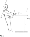
- Fig. 2 shows a side view of a standing workstation assembly 1 according to a first embodiment.
- a person 4 is also shown schematically, which stands on the bar table 2 and is supported in a direction away from the bar table 2 direction 5 in its lower back region 6 by a support device 3.
- the support device 3 is here as in relation to FIG Fig. 1 described, also provided as a loop 9.
- the loop 9 is formed here with a belt.
- an anchoring device 13 is provided on a surface 12 of the table top 11.
- the anchoring device 13 is here exemplified formed in the table top 11 spaced from each other attached ring hook.
- the strap has for anchoring a carabiner 19, which is hooked into the ring hook and secured therein.
- a carabiner 19 which is hooked into the ring hook and secured therein.
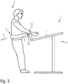
- Fig. 3 shows a side view of a standing workstation assembly 1 according to a second embodiment.
- a curved circumferential headband which extends from the surface of the table top 11 upwards.
- the table top 11 is here shown inclined, so that a front edge of the table is located further down than in Fig. 2 , Due to the curved headband, the effective anchoring point 20 is still considered at the same level as in absolute terms Fig. 1 arranged.
- the ergonomically most favorable height of the anchoring point 20 can thus be selected.
- the carabiner can be provided on the headband, for example, freely displaceable, in stages suspended or continuously, for example, with suitable locking means, durable to a desired height.
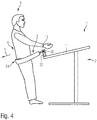
- Fig. 4 shows a side view of a standing workstation arrangement 1 according to a third embodiment.
- the height of the anchoring point 20 is not only changeable, but can also be fixed in a position to the course of the backdrop.
- the inclination angle of the support device 3, as shown here other than the inclination of the table top 11 are selected.
- the support device 3 runs obliquely downwards in comparison to the table top 11 and therefore the person 4 can support himself diagonally downwards.
- the support device 3 is preferably positioned in the buttocks area 24 of the person 4, so that the person 4 can support part of their weight on the support device 3 and thus, as in a conventional standing aid, a little way into the support device 3 ""can.
- Fig. 5 shows a side view of a standing workstation arrangement according to a fourth embodiment.
- a ring hook provided as anchoring means for anchoring, wherein the ring hook is arranged on an underside 14 of the table top 11. He is attached to a support 18 of the substructure 15.
- the person can be supported substantially horizontally to the rear, preferably in the lower back region 6, as shown here.
- the anchoring device 13 is thereby covered by the table top 11 and thus not visible.
- the range of motion and the work surface is not affected by the arranged on the underside of the table top 11 anchoring device 13.
- Fig. 6 shows a side view of a standing workstation assembly 1 according to a fifth embodiment.
- a curved circumferential headband provided as anchoring means wherein the headband is arranged here on the underside 14 of the table top 11.
- Such anchoring device 13 in particular leaves a great deal of leeway in the ergonomic design of small persons and so-called sitting giants, ie persons with comparatively short legs and long Upper body, too. In this case, a substantially horizontal is ensured even if the lower back region 6 of a person 4 is comparatively deep.
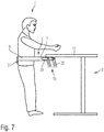
- Fig. 7 shows a side view of a standing workstation assembly 1 according to a sixth embodiment.
- the support device 3 is formed here with a rigid bracket 10 per se.
- the anchoring device 13 is formed here with a provided on the underside 14 of the table top 11 Doppelkulisse as adjusting means 22.
- the bracket 10 also has an adjusting means 23 in the form of a slot. Between the slot and the double gate two bolts are guided, which are non-positively detectable, especially on here for clarity, not shown locking means, such as wheel bolts, thumbscrews, lever screws, eccentric quick-release or the like.
- adjusting means 22, 23 for adjusting in two dimensions that is, in the height and depth direction, provided, which allow an adjustment of the height and the inclination of the bracket 10.
- the bracket 10 can be inclined relative to the table top 11. In addition, so the depth of the bracket 10 can be adjusted.
- the bracket 10 has in the area in which the person hangs 4, a pad 21.
- the bracket 10 can either, as in relation to Fig. 1 shown anchored at both ends 7, 8 or only at the first end 7 shown here in the manner shown. If the anchored only at the first end 7, the second end 8 is free and the person 4 can enter laterally without manipulation of the support device 3 in the bracket 10.
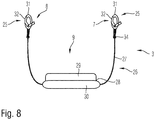
- Fig. 8 shows a schematic plan view of a support device 3 according to another embodiment.
- the support device 3 has two anchoring sections 25 and a support section 26.
- the anchoring portions 25 are each formed for anchoring to an anchoring device 13, not shown here.
- the support portion 26 is shown for supporting a standing person in a direction away from the anchoring portion 25 in the buttocks and / or lower back region, when the anchoring portions 25 are anchored in an anchoring device 13.
- An anchoring section 25 has in each case a suspension device 31 and a closure device 32.
- the closure device 32 By means of the closure device 32, the suspended in an anchoring device 13 hooking 31 is secured therein.
- the suspension device 31 is designed as an open hook and the closure device 32 as a karabiner closure closing the open hook.
- the support portion 26 is formed as a loop 9, which is provided so that a person standing in the anchored state can hang it.
- an anchoring portion 25 is provided in each case.
- the trained as a loop 9 support portion 26 has a backrest portion 28 and a power transmission area 27.
- the backrest region 28 is designed to accommodate the leaning forces of a standing person and has for this purpose a lower buttock support region 29 and an upper lumbar support region 30.
- the power transmission portion 27 transmits the leaning forces from the back portion 28 to the anchoring portion 25.
- the power transmission area 27 is designed as a belt.
- the backrest portion 28 may be formed in this case as threaded on the belt ergonomically shaped support and optionally provided with a cushion.
- each coupled pivot 34 is provided so as to provide a flexible orientation of the anchoring portion 25.
- Fig. 9 shows a schematic perspective view of the support device according to Fig. 8 .
- the ergonomic shape of the backrest region 28 with its lower buttock support region 29 and its upper lumbar support region 30 can be seen.
- the contour of the backrest area is curved so that the buttocks support area under the buttocks and thus a certain seating effect is generated. Further, the buttocks are partially enclosed by the back region 28, with support being provided to the lumbar support region 30 for lumbar support.
- the trained as a belt power transmission area 27 is performed through an opening 35 through the backrest portion 28.
- the backrest portion 28 can be moved along the belt, so that a dynamic support, for example, not only to the rear but also to one side, is possible.
- the power transmission region 27 may not be formed as, but as an elastic band. In this case, an elastic compliance is ensured, which is advantageous in a dynamic standing person.
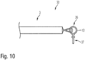
- Fig. 10 shows a schematic partial side view of a support assembly 33rd
- the support arrangement 33 has a support device 3 and an anchoring device 13.
- the support device 3 is in particular an embodiment of a loop 9, as in relation to the preceding one FIGS. 1 to 6 . 8th and 9 described, which is shown only schematically.
- the anchoring device 13 has a hooking section 36 and a fastening section 37. In the illustrated embodiment, by way of example, a threaded ring hook can be screwed into the table top.
- a loop 9 but also a bracket 10 can be pivotally anchored to the bar table 2, so that its height and inclination can be changed by pivoting.
Landscapes
- Rehabilitation Tools (AREA)
Applications Claiming Priority (1)
| Application Number | Priority Date | Filing Date | Title |
|---|---|---|---|
| DE202016006340.6U DE202016006340U1 (de) | 2016-10-13 | 2016-10-13 | Steharbeitsplatzanordnung |
Publications (1)
| Publication Number | Publication Date |
|---|---|
| EP3308676A1 true EP3308676A1 (fr) | 2018-04-18 |
Family
ID=57281680
Family Applications (1)
| Application Number | Title | Priority Date | Filing Date |
|---|---|---|---|
| EP17186425.9A Withdrawn EP3308676A1 (fr) | 2016-10-13 | 2017-08-16 | Dispositif de support, ensemble support et dispositif formant poste de travail debout |
Country Status (2)
| Country | Link |
|---|---|
| EP (1) | EP3308676A1 (fr) |
| DE (1) | DE202016006340U1 (fr) |
Cited By (1)
| Publication number | Priority date | Publication date | Assignee | Title |
|---|---|---|---|---|
| NL2037482B1 (en) * | 2024-04-17 | 2025-11-03 | Antonius Jozef Oudejans Erwin | Workspace unit for accommodating a person in a standing position |
Families Citing this family (1)
| Publication number | Priority date | Publication date | Assignee | Title |
|---|---|---|---|---|
| CN109602162A (zh) * | 2018-11-27 | 2019-04-12 | 杨旭 | 一种可调节式多功能讲桌 |
Citations (12)
| Publication number | Priority date | Publication date | Assignee | Title |
|---|---|---|---|---|
| US2603542A (en) * | 1949-03-23 | 1952-07-15 | Merle H Charters | Standing table for invalids |
| DE4304757A1 (de) * | 1993-02-17 | 1994-08-18 | Hans Peter Baranowski | Vorrichtung zum Anheben und Transportieren von Patienten sowie als Geh-, Steh- und/oder Aufstehhilfe |
| DE29818890U1 (de) | 1998-10-23 | 1998-12-24 | Herre, Hans-Werner, 75417 Mühlacker | Steharbeitsplatz mit einer Stehhilfe und einem Stehpult |
| DE19745295A1 (de) * | 1997-10-14 | 1999-04-15 | Richter Reha Design Gmbh | Stehpult mit integrierter Aufstehhilfe |
| DE102004053980A1 (de) * | 2004-11-09 | 2006-05-11 | Isko Koch Gmbh | Stehgerät zur Rehabilitation körperbeeinträchtigter Personen |
| DE102007039640A1 (de) * | 2007-08-22 | 2009-02-26 | Deckel Maho Pfronten Gmbh | Bedienpult für eine Werkzeugmaschine |
| SE532934C2 (sv) * | 2007-09-03 | 2010-05-11 | Aake Nilsson | Stödorgan för en stående användare |
| EP2468119A1 (fr) * | 2010-12-21 | 2012-06-27 | Consultiv AG | Veste de protection, notamment veste de protection contre l'incendie, dotée d'une ceinture intégrée |
| WO2013003369A2 (fr) | 2011-06-29 | 2013-01-03 | Equipois Inc. | Système de support pour le corps humain |
| FR3020750A1 (fr) | 2014-05-06 | 2015-11-13 | Prodergo | Dispositif de maintien corporel en position debout |
| FR3022443A1 (fr) * | 2014-06-20 | 2015-12-25 | Prodergo | Dispositif d'aide a la position debout ou assis-debout. |
| FR3032870A1 (fr) | 2015-02-20 | 2016-08-26 | Prodergo | Structure de mobilier repliable, en particulier de mobilier d'enseignement |
-
2016
- 2016-10-13 DE DE202016006340.6U patent/DE202016006340U1/de active Active
-
2017
- 2017-08-16 EP EP17186425.9A patent/EP3308676A1/fr not_active Withdrawn
Patent Citations (12)
| Publication number | Priority date | Publication date | Assignee | Title |
|---|---|---|---|---|
| US2603542A (en) * | 1949-03-23 | 1952-07-15 | Merle H Charters | Standing table for invalids |
| DE4304757A1 (de) * | 1993-02-17 | 1994-08-18 | Hans Peter Baranowski | Vorrichtung zum Anheben und Transportieren von Patienten sowie als Geh-, Steh- und/oder Aufstehhilfe |
| DE19745295A1 (de) * | 1997-10-14 | 1999-04-15 | Richter Reha Design Gmbh | Stehpult mit integrierter Aufstehhilfe |
| DE29818890U1 (de) | 1998-10-23 | 1998-12-24 | Herre, Hans-Werner, 75417 Mühlacker | Steharbeitsplatz mit einer Stehhilfe und einem Stehpult |
| DE102004053980A1 (de) * | 2004-11-09 | 2006-05-11 | Isko Koch Gmbh | Stehgerät zur Rehabilitation körperbeeinträchtigter Personen |
| DE102007039640A1 (de) * | 2007-08-22 | 2009-02-26 | Deckel Maho Pfronten Gmbh | Bedienpult für eine Werkzeugmaschine |
| SE532934C2 (sv) * | 2007-09-03 | 2010-05-11 | Aake Nilsson | Stödorgan för en stående användare |
| EP2468119A1 (fr) * | 2010-12-21 | 2012-06-27 | Consultiv AG | Veste de protection, notamment veste de protection contre l'incendie, dotée d'une ceinture intégrée |
| WO2013003369A2 (fr) | 2011-06-29 | 2013-01-03 | Equipois Inc. | Système de support pour le corps humain |
| FR3020750A1 (fr) | 2014-05-06 | 2015-11-13 | Prodergo | Dispositif de maintien corporel en position debout |
| FR3022443A1 (fr) * | 2014-06-20 | 2015-12-25 | Prodergo | Dispositif d'aide a la position debout ou assis-debout. |
| FR3032870A1 (fr) | 2015-02-20 | 2016-08-26 | Prodergo | Structure de mobilier repliable, en particulier de mobilier d'enseignement |
Cited By (1)
| Publication number | Priority date | Publication date | Assignee | Title |
|---|---|---|---|---|
| NL2037482B1 (en) * | 2024-04-17 | 2025-11-03 | Antonius Jozef Oudejans Erwin | Workspace unit for accommodating a person in a standing position |
Also Published As
| Publication number | Publication date |
|---|---|
| DE202016006340U1 (de) | 2016-10-26 |
Similar Documents
| Publication | Publication Date | Title |
|---|---|---|
| DE3879714T2 (de) | Ergonomischer stuhl mit einem verstellbaren sitz. | |
| DE69830610T2 (de) | Synchronstuhl mit verstellbarem sitz und rückenlehne | |
| DE60300064T2 (de) | Stuhl mit beweglichem Sitz und Rückenlehne | |
| DE69928538T2 (de) | Stuhl | |
| DE202004004800U1 (de) | Verstellbarer Büro-Lehnstuhl mit Gelenk zur synchronen Bewegung des Sitzes und der Rückenlehne | |
| DE10048781A1 (de) | Nackenstütze für einen Stuhl | |
| DE2001097A1 (de) | Kombinierter Buero- und Ruhestuhl | |
| DE202007013812U1 (de) | Sitzschale für Behinderte, insbesondere für behinderte Kinder und Jugendliche | |
| DE3779696T2 (de) | Verstellbare stuehle. | |
| EP3669849B1 (fr) | Aide au relèvement permettant de relever une personne | |
| DE3903388C2 (fr) | ||
| EP3308676A1 (fr) | Dispositif de support, ensemble support et dispositif formant poste de travail debout | |
| DE8019712U1 (de) | Ausschiebbare und neigbare fussstuetze fuer sitz- und liegemoebel | |
| DE2000172C3 (de) | Stuhl, insbesondere Arbeitsstuhl | |
| DE2438295A1 (de) | Sitzmoebel mit rueckenlehne | |
| DE3639474C2 (fr) | ||
| DE20307043U1 (de) | Stufenlos höhenverstellbarer universell anpaßbarer Stuhl | |
| AT395529B (de) | Behandlungsliege, insbesondere massageliege | |
| DE102013003746B4 (de) | Stuhl, Krafttrainingsgerät und Verwendung eines Stuhls als Krafttrainingsgerät | |
| DE1152232B (de) | Sitze, insbesondere Arbeitssitz, mit einer hinteren, keilartig ansteigenden Stuetzflaeche fuer Hocker, Stuehle od. dgl. | |
| DE19938334B4 (de) | Schaukelstuhl und/oder -liege | |
| AT411006B (de) | Sitzvorrichtung zur auflage auf einem sitzmöbel | |
| DE3138123A1 (de) | Sitzmoebel | |
| EP4056072B1 (fr) | Siège | |
| DE69216326T2 (de) | Steharbeitssitz |
Legal Events
| Date | Code | Title | Description |
|---|---|---|---|
| PUAI | Public reference made under article 153(3) epc to a published international application that has entered the european phase |
Free format text: ORIGINAL CODE: 0009012 |
|
| STAA | Information on the status of an ep patent application or granted ep patent |
Free format text: STATUS: THE APPLICATION HAS BEEN PUBLISHED |
|
| AK | Designated contracting states |
Kind code of ref document: A1 Designated state(s): AL AT BE BG CH CY CZ DE DK EE ES FI FR GB GR HR HU IE IS IT LI LT LU LV MC MK MT NL NO PL PT RO RS SE SI SK SM TR |
|
| AX | Request for extension of the european patent |
Extension state: BA ME |
|
| TPAC | Observations filed by third parties |
Free format text: ORIGINAL CODE: EPIDOSNTIPA |
|
| STAA | Information on the status of an ep patent application or granted ep patent |
Free format text: STATUS: REQUEST FOR EXAMINATION WAS MADE |
|
| 17P | Request for examination filed |
Effective date: 20181012 |
|
| RBV | Designated contracting states (corrected) |
Designated state(s): AL AT BE BG CH CY CZ DE DK EE ES FI FR GB GR HR HU IE IS IT LI LT LU LV MC MK MT NL NO PL PT RO RS SE SI SK SM TR |
|
| STAA | Information on the status of an ep patent application or granted ep patent |
Free format text: STATUS: EXAMINATION IS IN PROGRESS |
|
| 17Q | First examination report despatched |
Effective date: 20181204 |
|
| STAA | Information on the status of an ep patent application or granted ep patent |
Free format text: STATUS: THE APPLICATION IS DEEMED TO BE WITHDRAWN |
|
| 18D | Application deemed to be withdrawn |
Effective date: 20190416 |