EP3308687A1 - Collecteur de poussière portable ayant une structure de séparation poussière/air en tornade à deux étages en spirale - Google Patents
Collecteur de poussière portable ayant une structure de séparation poussière/air en tornade à deux étages en spirale Download PDFInfo
- Publication number
- EP3308687A1 EP3308687A1 EP15894802.6A EP15894802A EP3308687A1 EP 3308687 A1 EP3308687 A1 EP 3308687A1 EP 15894802 A EP15894802 A EP 15894802A EP 3308687 A1 EP3308687 A1 EP 3308687A1
- Authority
- EP
- European Patent Office
- Prior art keywords
- dust
- stage
- air
- air separation
- spiral
- Prior art date
- Legal status (The legal status is an assumption and is not a legal conclusion. Google has not performed a legal analysis and makes no representation as to the accuracy of the status listed.)
- Granted
Links
Images





Classifications
-
- A—HUMAN NECESSITIES
- A47—FURNITURE; DOMESTIC ARTICLES OR APPLIANCES; COFFEE MILLS; SPICE MILLS; SUCTION CLEANERS IN GENERAL
- A47L—DOMESTIC WASHING OR CLEANING; SUCTION CLEANERS IN GENERAL
- A47L9/00—Details or accessories of suction cleaners, e.g. mechanical means for controlling the suction or for effecting pulsating action; Storing devices specially adapted to suction cleaners or parts thereof; Carrying-vehicles specially adapted for suction cleaners
- A47L9/10—Filters; Dust separators; Dust removal; Automatic exchange of filters
- A47L9/16—Arrangement or disposition of cyclones or other devices with centrifugal action
- A47L9/1608—Cyclonic chamber constructions
-
- A—HUMAN NECESSITIES
- A47—FURNITURE; DOMESTIC ARTICLES OR APPLIANCES; COFFEE MILLS; SPICE MILLS; SUCTION CLEANERS IN GENERAL
- A47L—DOMESTIC WASHING OR CLEANING; SUCTION CLEANERS IN GENERAL
- A47L5/00—Structural features of suction cleaners
- A47L5/12—Structural features of suction cleaners with power-driven air-pumps or air-compressors, e.g. driven by motor vehicle engine vacuum
- A47L5/22—Structural features of suction cleaners with power-driven air-pumps or air-compressors, e.g. driven by motor vehicle engine vacuum with rotary fans
- A47L5/24—Hand-supported suction cleaners
-
- A—HUMAN NECESSITIES
- A47—FURNITURE; DOMESTIC ARTICLES OR APPLIANCES; COFFEE MILLS; SPICE MILLS; SUCTION CLEANERS IN GENERAL
- A47L—DOMESTIC WASHING OR CLEANING; SUCTION CLEANERS IN GENERAL
- A47L5/00—Structural features of suction cleaners
- A47L5/12—Structural features of suction cleaners with power-driven air-pumps or air-compressors, e.g. driven by motor vehicle engine vacuum
- A47L5/22—Structural features of suction cleaners with power-driven air-pumps or air-compressors, e.g. driven by motor vehicle engine vacuum with rotary fans
- A47L5/28—Suction cleaners with handles and nozzles fixed on the casings, e.g. wheeled suction cleaners with steering handle
-
- A—HUMAN NECESSITIES
- A47—FURNITURE; DOMESTIC ARTICLES OR APPLIANCES; COFFEE MILLS; SPICE MILLS; SUCTION CLEANERS IN GENERAL
- A47L—DOMESTIC WASHING OR CLEANING; SUCTION CLEANERS IN GENERAL
- A47L9/00—Details or accessories of suction cleaners, e.g. mechanical means for controlling the suction or for effecting pulsating action; Storing devices specially adapted to suction cleaners or parts thereof; Carrying-vehicles specially adapted for suction cleaners
- A47L9/10—Filters; Dust separators; Dust removal; Automatic exchange of filters
- A47L9/12—Dry filters
-
- A—HUMAN NECESSITIES
- A47—FURNITURE; DOMESTIC ARTICLES OR APPLIANCES; COFFEE MILLS; SPICE MILLS; SUCTION CLEANERS IN GENERAL
- A47L—DOMESTIC WASHING OR CLEANING; SUCTION CLEANERS IN GENERAL
- A47L9/00—Details or accessories of suction cleaners, e.g. mechanical means for controlling the suction or for effecting pulsating action; Storing devices specially adapted to suction cleaners or parts thereof; Carrying-vehicles specially adapted for suction cleaners
- A47L9/10—Filters; Dust separators; Dust removal; Automatic exchange of filters
- A47L9/16—Arrangement or disposition of cyclones or other devices with centrifugal action
- A47L9/1616—Multiple arrangement thereof
- A47L9/1625—Multiple arrangement thereof for series flow
- A47L9/1633—Concentric cyclones
-
- A—HUMAN NECESSITIES
- A47—FURNITURE; DOMESTIC ARTICLES OR APPLIANCES; COFFEE MILLS; SPICE MILLS; SUCTION CLEANERS IN GENERAL
- A47L—DOMESTIC WASHING OR CLEANING; SUCTION CLEANERS IN GENERAL
- A47L9/00—Details or accessories of suction cleaners, e.g. mechanical means for controlling the suction or for effecting pulsating action; Storing devices specially adapted to suction cleaners or parts thereof; Carrying-vehicles specially adapted for suction cleaners
- A47L9/10—Filters; Dust separators; Dust removal; Automatic exchange of filters
- A47L9/16—Arrangement or disposition of cyclones or other devices with centrifugal action
- A47L9/165—Construction of inlets
-
- A—HUMAN NECESSITIES
- A47—FURNITURE; DOMESTIC ARTICLES OR APPLIANCES; COFFEE MILLS; SPICE MILLS; SUCTION CLEANERS IN GENERAL
- A47L—DOMESTIC WASHING OR CLEANING; SUCTION CLEANERS IN GENERAL
- A47L9/00—Details or accessories of suction cleaners, e.g. mechanical means for controlling the suction or for effecting pulsating action; Storing devices specially adapted to suction cleaners or parts thereof; Carrying-vehicles specially adapted for suction cleaners
- A47L9/10—Filters; Dust separators; Dust removal; Automatic exchange of filters
- A47L9/16—Arrangement or disposition of cyclones or other devices with centrifugal action
- A47L9/1658—Construction of outlets
- A47L9/1666—Construction of outlets with filtering means
-
- A—HUMAN NECESSITIES
- A47—FURNITURE; DOMESTIC ARTICLES OR APPLIANCES; COFFEE MILLS; SPICE MILLS; SUCTION CLEANERS IN GENERAL
- A47L—DOMESTIC WASHING OR CLEANING; SUCTION CLEANERS IN GENERAL
- A47L9/00—Details or accessories of suction cleaners, e.g. mechanical means for controlling the suction or for effecting pulsating action; Storing devices specially adapted to suction cleaners or parts thereof; Carrying-vehicles specially adapted for suction cleaners
- A47L9/10—Filters; Dust separators; Dust removal; Automatic exchange of filters
- A47L9/16—Arrangement or disposition of cyclones or other devices with centrifugal action
- A47L9/1683—Dust collecting chambers; Dust collecting receptacles
Definitions
- the present application relates to the technical field of manufacturing of dust collectors, and in particular to a handheld dust collector having a spiral two-stage tornado dust-air separation structure.
- Dust collectors as articles for daily use, are widely used for the cleaning of indoor and outdoor.
- a dust collector is a cleaning appliance, in which air negative pressure is created in a sealed housing, by using vanes to rotate at a high speed with a motor, for sucking dust into a dust collecting device and discharging filtered air from a fan at an extremely high speed.
- the dust collectors are classified into dry type dust collectors and wet-dry type dust collectors according to their functions.
- the dry type dust collectors generally include dust-bag type dust collectors and machine-body type dust collectors.
- the dust collectors may be classified, according to their shapes, into horizontal dust collectors, vertical dust collectors and handheld dust collectors, and so on.
- the handheld dust collectors are convenient for cleaning articles such as a wall surface, a sofa, a windowsill, a desktop and an electrical appliance.
- a dust-air separation mode of a dust collecting part of a conventional handheld dust collector is generally of a first-stage centrifugal separation mode or a dust-bag filtering mode, and both of the two filtering modes have a low filtering efficiency and are apt to cause blockage.
- a conventional two-stage separation type machine body generally includes a two-stage dust-air separation structure.
- a first-stage structure is used for filtering large dirt in air
- a second-stage structure is used for separating and collecting small dirt such as dust particles.
- a second-stage cyclone is generally formed by cooperation between a cover plate for a filter of the machine body and a cyclone body having several cyclone openings.
- Such a structure requires a lot of parts and components, and further involves relatively more and complicated molds and assembly processes. Further, each link is difficult to be sealed, and it is apt to occur air leakage and dust leakage phenomena, which adversely affects comprehensive performance of the whole machine.
- Chinese Patent CN 200520102558.7 discloses an integrated two-stage separation type machine body.
- the structure of the machine body is laid out in an axial direction, in which an inner tube and an outer tube of a dust removal device are axially arranged for separating the dust from the air.
- a second-stage dust barrel since being arranged in a first-stage dust barrel, occupies space of the first-stage dust barrel, which occupies a most dust-collecting volume of the machine body, and causes a limited dust storage space and affected dust suction effect.
- an air return area of the second-stage dust barrel is small, resulting in a low air volume of the whole machine.
- this two-stage dust-air separation type machine body requires the machine body to have a relatively large height and a relatively large volume, and the shape of the machine body is not applicable for a portable handheld dust collector, and the application scope thereof is limited. Also, since the handheld dust collector has great flexibility and has its orientation changed at any time at work, the dust in the conventional machine body is prone to back flow.
- a handheld dust collector having a spiral two-stage tornado dust-air separation structure is provided according to the present application.
- a machine body of the handheld dust collector is provided therein with a spiral two-stage tornado dust-air separation structure which has a shape conforming to the handheld dust collector.
- the handheld dust collector has fewer components and is easy to assemble, and comprehensive performance of the whole machine is improved.
- the space of the machine body occupied by the two-stage dust-air separation structure is reduced effectively, and a maximum dust storage volume is achieved, and thus dust collection efficiency is improved and dust backflow is prevented effectively.
- an accommodating space is provided in a machine body of the handheld dust collector.
- a spiral two-stage tornado dust-air separation structure is provided in the accommodating space, and a portion of the accommodating space at a different side of the spiral two-stage tornado dust-air separation structure forms a first-stage dust barrel.
- a portion of the accommodating space at a same side of the spiral two-stage tornado dust-air separation structure constrain a first-stage cyclone barrel of the spiral two-stage tornado dust-air separation structure.
- the spiral two-stage tornado dust-air separation structure includes a first-stage cyclone barrel, a second-stage cyclone barrel, a spiral dust-air separation device and a cyclone cover.
- the second-stage cyclone barrel is arranged in the first-stage cyclone barrel.
- the spiral dust-air separation device is arranged at an upper end of the second-stage cyclone barrel.
- the cyclone cover is arranged between the first-stage cyclone barrel and the second-stage cyclone barrel.
- a gap is provided between the second-stage cyclone barrel and an inner wall of the cyclone cover. The gap forms second-stage dust-air separation air duct which is used after a first-stage dust-air separation.
- the first-stage cyclone barrel and the cyclone cover perform the first-stage dust-air separation on primary dusty air which enters the two-stage dust-air separation device. Dusty air, after being subjected to the first-stage dust-air separation, enters the second-stage cyclone barrel to be subjected to a second-stage dust-air separation.
- the handheld dust collector includes a machine body air inlet.
- the first-stage cyclone barrel includes a first-stage dust shedding opening.
- the dust enters the first-stage cyclone barrel via the machine body air inlet to be subjected to the first-stage dust-air separation.
- the dust enters the first-stage dust barrel via the first-stage dust shedding opening under a centrifugal force.
- a second-stage dust collecting device is arranged below the second-stage cyclone barrel.
- the bottom of the second cyclone barrel forms the top of the second-stage dust collecting device.
- a sidewall of the second-stage cyclone barrel is provided with a second-stage dust shedding opening at a position close to the bottom of the second-stage cyclone barrel.
- the second-stage dust collecting device includes a dust intake body and a dust channel.
- the dust channel extends to the bottom of the machine body to abut against the first-stage dust barrel.
- the dust intake body and the dust channel are hermetically connected or integrally molded.
- At least a part of the dust intake body or at least a part of the dust channel or at least part of each of the dust intake body and the dust channel has a side formed by an inner side of the machine body, or the dust intake body or the dust channel or each of the dust intake body and the dust channel forms an independent second-stage dust collecting space.
- a central portion of the bottom of the second-stage cyclone barrel is designed to project downward, thereby preventing the dust from back flowing.
- a dust retaining barrel is provided in the second-stage cyclone barrel.
- a gap is provided between the dust retaining barrel and the second-stage cyclone barrel, and the gap forms a second-stage dust-air separation air duct.
- An inner side wall of the dust retaining barrel constrains the dusty air from rotating in the dust retaining barrel to generate a centrifugal force for resisting suction of negative pressure.
- the dusty air is subjected to a first stage dust-air separation by the cyclone cover
- at least part of the dusty air is guided to the spiral dust-air separation device through the second-stage dust-air separation air duct, and forms, at an inner wall of the second-stage cyclone barrel, airflow rotating towards the bottom of the second-stage cyclone barrel under guidance of the spiral dust-air separation device.
- Dust in the airflow driven by a centrifugal force, rotates downward to the bottom of the second-stage cyclone barrel and is collected in the second-stage dust collecting space, and air in the rotating airflow is sucked out of an air outlet of the spiral two-stage tornado dust-air separation structure by the negative pressure, and thus the second-stage dust-air separation is realized.
- a filtering device is further provided at an upper end of an air outlet of the machine body.
- the filtering device may be a cotton filter.
- the dusty air having a small dust concentration is subjected to a final filtration by the cotton filter after passing through the air outlet of the machine body.
- the spiral dust-air separation device includes a spiral impeller for generating second-stage cyclone.
- the spiral impeller is provided with several downward-inclined vanes, and the vanes constrain the dusty air to swoop down obliquely.
- the spiral dust-air separation device further includes an inner ring arranged on an inner periphery of the spiral impeller.
- Multiple guidance tangent planes are provided on a side wall, corresponding to an air outlet of the spiral impeller, of the inner ring. The guidance tangent planes constrain the dusty air to flow to an outer periphery of the spiral impeller, and thus the dusty air begins to be in rotation.
- an overall air-intake area of the spiral impeller is less than an air-outgoing area of the spiral two-stage tornado dust-air separation structure, making the centrifugal force created by rotation of the dusty air sufficient to resist suction of the negative pressure.
- the handheld dust collector disclosed according to the present application has the following advantages.
- the handheld dust collector employs the spiral two-stage tornado dust-air separation structure, filtering efficiency is improved, parts and components of the structure are reduced, assembly process is simplified and comprehensive performance of the whole machine is improved with respect to employing a conventional dust collecting mode.
- the dust-air separation structure has a small volume, which reduces the space of the machine body occupied by the dust-air separation structure, achieves a maximum dust storage capacity and improves dust collecting efficiency.
- the spiral two-stage tornado dust-air separation structure and the dust barrel have shapes designed to conform to the shape of the handheld dust collector, and are therefore applicable for the handheld dust collector.
- the central part of the bottom of the second-stage cyclone barrel is designed to project downward, and thus the dust is not apt to back flow.
- the second-stage dust collecting device extends directly to the bottom of the machine body, and a part of the second-stage dust collecting device has a side formed by an inner side of the machine body, thereby saving materials and facilitating dumping dust.
- a filtering device is provided at the upper end of the air outlet of the machine body.
- the filtering device prevents the dust from being dumped out of the air outlet, and thus the final filtration is realized.
- a conventional two-stage dust-air separation structure requires a lot of parts and components, and further involves relatively more and complicated molds and assembly processes, and each link is difficult to be sealed, thus air leakage and dust leakage phenomena are apt to occur, which adversely affects comprehensive performance of a whole machine.
- the conventional two-stage dust-air separation type machine body structure is axially laid out, thus its filter structure occupies a large portion of the space of a machine body and occupies a most dust collecting volume of the machine body, and a dust storage space is limited.
- this two-stage dust-air separation machine body structure requires the machine body to have a relatively large height and a relatively large volume, thus the shape of the machine body structure is not applicable for a portable handheld dust collector, and the application scope thereof is limited.
- a handheld dust collector having a spiral two-stage tornado dust-air separation structure which reduces the number of the parts of the structure, simplifies the assembly process, improves the comprehensive performance of the whole machine and also effectively reduces space occupied by a two-stage dust-air separation structure, thereby achieving a maximum dust storage volume, improving dust collection efficiency.
- shapes of the spiral two-stage tornado dust-air separation structure and a dust barrel are designed to conform to the shape of the handheld dust collector, so as to be applicable for the handheld dust collector.
- a handheld dust collector is provided.
- An accommodating space is provided in a machine body.
- a spiral two-stage tornado dust-air separation structure is provided in the accommodating space.
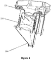
- a portion of the accommodating space at a different side of the spiral two-stage tornado dust-air separation structure forms a first-stage dust barrel 110, and a portion of the accommodating space at a same side of the spiral two-stage tornado dust-air separation structure constitutes a first-stage cyclone barrel 210 of the spiral two-stage tornado dust-air separation structure.
- the spiral two-stage tornado dust-air separation structure includes the first-stage cyclone barrel 210, a second-stage cyclone barrel 212 and a cyclone cover 211.
- the second-stage cyclone barrel 212 is arranged in the first-stage cyclone barrel 210, and the cyclone cover 211 is arranged between the first-stage cyclone barrel and the second-stage cyclone barrel.
- a gap is provided between the second-stage cyclone barrel and an inner wall of the cyclone cover. The gap forms a second-stage dust-air separation air duct 216, which is used after a first-stage dust-air separation.
- the first-stage cyclone barrel includes a first-stage dust shedding opening 111.
- the first-stage cyclone barrel 210 and the cyclone cover 211 carry out a first-stage dust-air separation on primary dusty air which enters the first-stage cyclone barrel.
- Dust enters the first-stage dust barrel 110 via the first-stage dust shedding opening 111 under a centrifugal force.
- the dusty air with a low dust concentration after being subjected to the first-stage separation, is sucked into the second-stage dust-air separation air duct 216 by a mesh screen of the cyclone cover, forming a second-stage cyclone under constraint of the second-stage cyclone barrel after passing through a spiral dust-air separation device.
- a spiral groove 231 is provided at an inner side of an upper end of the cyclone cover, which allows airflow to rotate at the upper end of the cyclone cover and create a centrifugal force, and is convenient for the airflow to rotate downward into the spiral dust-air separation device.
- a spiral dust-air separation device 220 is provided at an upper barrel opening of the second-stage cyclone barrel 212. After the dusty air is subjected to a first stage dust-air separation by the cyclone cover 211, at least a part of the dusty air is guided to the spiral dust-air separation device 220 through the second-stage dust-air separation air duct 216, and forms, at an inner wall of the second-stage cyclone barrel 212, airflow rotating towards the bottom of the second-stage cyclone barrel under guidance of the spiral dust-air separation device.
- a second-stage dust collecting device 214 is provided under the second-stage cyclone barrel 212. The bottom of the second-stage cyclone barrel forms the top of the second-stage dust collecting device.
- the second-stage cyclone barrel is hermetically connected to or integrally molded with the second-stage dust collecting device.
- a sidewall of the second-stage cyclone barrel 212 is provided with a second-stage dust shedding opening 217 at a position close to the bottom of the second-stage cyclone barrel 212, and a central portion of the bottom of the second-stage cyclone barrel 212 is designed to project downward at a position close to the second-stage dust shedding opening 217.
- Dust in secondary dusty air is driven by the centrifugal force to rotate downward to the bottom of the second-stage cyclone barrel, and enters the second-stage dust collecting device 214 via the second-stage dust shedding opening 217, and the air in rotating airflow is sucked by a negative pressure, thereby realizing the second-stage dust-air separation.
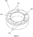
- the spiral dust-air separation device 220 includes a spiral impeller 221 for generating second-stage cyclone.
- the spiral impeller 221 is provided with several downward-inclined vanes, and the vanes can constrain the dusty air to swoop down obliquely to form spiral airflow.
- the spiral dust-air separation device 220 further includes an inner ring 222 arranged on an inner periphery of the spiral impeller 221.
- Several guidance tangent planes 223 are arranged on a side wall, corresponding to an air outlet of the spiral impeller 221, of the inner ring 222.
- the guidance tangent planes constrain the dusty air to flow to an outer periphery of the spiral impeller, and thus the dusty air begins to be in a rotating state.
- An outer ring is provided at an outer periphery of the spiral impeller. With the inner ring and the outer ring, the airflow is guided, and the structural strength and stability of the spiral impeller are improved.
- a wind shielding plate 224 extends downward from a wall of the inner ring of the spiral impeller.
- a dust retaining barrel 215 is provided in the second-state cyclone barrel 212.
- a gap is provided between the dust retaining barrel and the second-stage cyclone barrel, and the gap forms the second-stage dust-air separation air duct 216.
- the dusty air rotates spirally in the second-stage dust-air separation air duct to generate a centrifugal force, so as to enable the dust to fall down along the inner wall of the second-stage cyclone barrel.
- An inner side wall of the dust retaining barrel can constrain the dusty air to rotate in the dust retaining barrel, so as to generate a centrifugal force for resisting suction of the negative pressure, thereby realizing effective separation of dust from air.
- the second-stage dust collecting device includes a dust intake body 232 and a dust channel 233.
- the dust intake body 232 and the dust channel 233 are hermetically connected through a sealing ring.
- the dust channel 233 may take an inner side of the machine body as its side, and extend to a lower part of the machine body to abut against the first-stage dust barrel. In this case, when clearing the dust collector of dust, all the dust falls into the first-stage dust barrel and the dust channel.
- the dust intake body 232 may be separated from the dust channel 233, and the dust may be dumped.
- a filtering device 230 is further provided at an upper end of an air outlet of the machine body.
- the filtering device may be a cotton filter.
- the dusty air having a small dust concentration is subjected to a final filtration by the cotton filter after passing through the air outlet of the machine body.
- the second-stage cyclone barrel and the spiral dust-air separation device may each have an integrally formed structure. After being molded, the spiral dust-air separation device is mounted directly at a central position of the second-stage cyclone barrel to complete the assembly.
- the specific molding manner is not limited.
- spiral two-stage tornado dust-air separation structure may also be integrally molded.
- the specific molding and assembling manner is not limited.
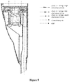
- an accommodating space is provided in a machine body 100.
- a spiral two-stage tornado dust-air separation structure is provided in the accommodating space.
- a portion of the accommodating space at a different side of the spiral two-stage tornado dust-air separation structure forms a first-stage dust barrel 110, and a portion of the accommodating space at a same side of the spiral two-stage tornado dust-air separation structure forms a first-stage cyclone barrel 210 of the spiral two-stage tornado dust-air separation structure.
- the spiral two-stage tornado dust-air separation structure includes the first-stage cyclone barrel 210, a second-stage cyclone barrel 212 and a cyclone cover 211.
- the second-stage cyclone barrel 212 is arranged in the first-stage cyclone barrel 210, and the cyclone cover 211 is arranged between the first-stage cyclone barrel and the second-stage cyclone barrel.
- a lower part of the machine body is provided with an air inlet 120, and an air outlet 130 is arranged on an upper side of the machine body.
- the dusty air is guided by the air inlet to the cyclone cover of the two-stage dust-air separation structure, and after the dusty air is subjected to a first stage dust-air separation by the cyclone cover 211, at least a part of the dusty air enters a second-stage cyclone barrel 212 through the cyclone cover, to be subjected to a second stage dust-air separation.
- An overall air-intake area of the spiral impeller 221 is less than an air-outgoing area of the machine body, enabling the dusty air to have a higher rotation speed to resist suction of negative pressure under same air volume.
- a partition plate 140 is arranged in the machine body, and an opening 150 extends downward from a center of the partition plate.
- the air subjected to the second stage dust-air separation is sucked by the negative pressure.
- the partition plate By providing the partition plate to shield an upper end of the cyclone cover, the dusty air after being filtered by the cyclone cover may be guided from an upper end of the second-stage dust-air separation air duct into the spiral dust-air separation device, which realizes guidance to ingoing air.
- a central part of the partition plate has a downward-inclined arc-shaped structure, which facilitates guiding the movement of the dusty air.
- a handheld dust collector which includes a spiral two-stage tornado dust-air separation structure and a first-stage dust barrel.
- the spiral two-stage tornado dust-air separation structure simply including a first-stage cyclone barrel, a second-stage cyclone barrel, a cyclone cover and a spiral dust-air separation device, may just achieve filtration and separation of the dusty air, which reduces the number of parts and components of the spiral two-stage tornado dust-air separation structure effectively and simplifies the assembly process, and facilitate improvement of the comprehensive performance of the whole machine.
- the spiral two-stage tornado dust-air separation structure has a small volume, which reduces space occupied by the two-stage separation structure effectively, realizes a maximum dust storage volume and improves the dust collection efficiency, and in particular makes the spiral two-stage tornado dust-air separation structure be applicable for the handheld dust collector.
- the second-stage dust collecting device extends directly to the bottom of the machine body, and takes the inner side of the machine body as its side, which saves materials and facilitates dumping dust.
Landscapes
- Engineering & Computer Science (AREA)
- Mechanical Engineering (AREA)
- Filters For Electric Vacuum Cleaners (AREA)
- Cyclones (AREA)
Applications Claiming Priority (2)
| Application Number | Priority Date | Filing Date | Title |
|---|---|---|---|
| CN201510313317.5A CN104840152A (zh) | 2015-06-09 | 2015-06-09 | 一种具有螺旋式二级龙卷风尘气分离结构的手持式吸尘器 |
| PCT/CN2015/094975 WO2016197546A1 (fr) | 2015-06-09 | 2015-11-19 | Collecteur de poussière portable ayant une structure de séparation poussière/air en tornade à deux étages en spirale |
Publications (3)
| Publication Number | Publication Date |
|---|---|
| EP3308687A1 true EP3308687A1 (fr) | 2018-04-18 |
| EP3308687A4 EP3308687A4 (fr) | 2019-02-20 |
| EP3308687B1 EP3308687B1 (fr) | 2023-03-22 |
Family
ID=53840435
Family Applications (1)
| Application Number | Title | Priority Date | Filing Date |
|---|---|---|---|
| EP15894802.6A Active EP3308687B1 (fr) | 2015-06-09 | 2015-11-19 | Collecteur de poussière portable ayant une structure de séparation poussière/air en tornade à deux étages en spirale |
Country Status (4)
| Country | Link |
|---|---|
| US (1) | US10568479B2 (fr) |
| EP (1) | EP3308687B1 (fr) |
| CN (1) | CN104840152A (fr) |
| WO (1) | WO2016197546A1 (fr) |
Families Citing this family (37)
| Publication number | Priority date | Publication date | Assignee | Title |
|---|---|---|---|---|
| CN104840152A (zh) | 2015-06-09 | 2015-08-19 | 莱克电气股份有限公司 | 一种具有螺旋式二级龙卷风尘气分离结构的手持式吸尘器 |
| GB2542387B (en) | 2015-09-17 | 2017-11-01 | Dyson Technology Ltd | Vacuum cleaner |
| GB2542385B (en) | 2015-09-17 | 2018-10-10 | Dyson Technology Ltd | Vacuum Cleaner |
| GB2542386B (en) | 2015-09-17 | 2018-10-10 | Dyson Technology Ltd | Vacuum Cleaner |
| CN105249891B (zh) * | 2015-11-03 | 2018-01-30 | 莱克电气股份有限公司 | 一种三级龙卷风尘杯过滤系统及包含该系统的吸尘器 |
| CN105266719B (zh) * | 2015-11-03 | 2016-08-31 | 莱克电气股份有限公司 | 一种多级龙卷风吸尘器尘杯结构 |
| US10786126B2 (en) | 2015-11-10 | 2020-09-29 | Techtronic Industries Co. Ltd. | Handheld vacuum cleaner |
| EP4413908A3 (fr) * | 2016-03-31 | 2024-11-27 | LG Electronics Inc. | Appareil de nettoyage |
| WO2017171496A1 (fr) | 2016-03-31 | 2017-10-05 | 엘지전자 주식회사 | Appareil de nettoyage |
| US11166607B2 (en) | 2016-03-31 | 2021-11-09 | Lg Electronics Inc. | Cleaner |
| KR102560970B1 (ko) | 2016-03-31 | 2023-07-31 | 엘지전자 주식회사 | 청소기 |
| WO2017177318A1 (fr) * | 2016-04-11 | 2017-10-19 | Omachron Intellectual Property Inc. | Appareil de nettoyage de surface |
| US10258210B2 (en) * | 2016-12-27 | 2019-04-16 | Omachron Intellectual Property Inc. | Multistage cyclone and surface cleaning apparatus having same |
| US10271704B2 (en) | 2016-12-27 | 2019-04-30 | Omachron Intellectual Property Inc. | Multistage cyclone and surface cleaning apparatus having same |
| US10405709B2 (en) | 2016-12-27 | 2019-09-10 | Omachron Intellectual Property Inc. | Multistage cyclone and surface cleaning apparatus having same |
| US10299643B2 (en) | 2016-12-27 | 2019-05-28 | Omachron Intellectual Property Inc. | Multistage cyclone and surface cleaning apparatus having same |
| US11285495B2 (en) | 2016-12-27 | 2022-03-29 | Omachron Intellectual Property Inc. | Multistage cyclone and surface cleaning apparatus having same |
| US10827891B2 (en) | 2016-12-27 | 2020-11-10 | Omachron Intellectual Property Inc. | Multistage cyclone and surface cleaning apparatus having same |
| WO2018119510A1 (fr) * | 2016-12-27 | 2018-07-05 | Omachron Intellectual Property Inc. | Cyclone à étages multiples et appareil de nettoyage de surface doté du cyclone à étages multiples |
| US10016106B1 (en) | 2016-12-27 | 2018-07-10 | Omachron Intellectual Property Inc. | Multistage cyclone and surface cleaning apparatus having same |
| CN106725092A (zh) * | 2017-01-24 | 2017-05-31 | 苏州市利飞特电器有限公司 | 一种挂靠式手持吸尘器 |
| US11745190B2 (en) | 2019-01-23 | 2023-09-05 | Omachron Intellectual Property Inc. | Surface cleaning apparatus |
| CN107343774A (zh) * | 2017-09-12 | 2017-11-14 | 苏州诚河清洁设备有限公司 | 手持式吸尘器 |
| US10820772B2 (en) | 2017-09-15 | 2020-11-03 | Omachron Intellectual Property Inc. | Surface cleaning apparatus |
| CN107595204B (zh) * | 2017-10-31 | 2022-10-25 | 卓力电器集团有限公司 | 一种可以吸水的二级尘气分离旋风式尘杯及其吸尘器 |
| CN109157159A (zh) * | 2018-08-29 | 2019-01-08 | 宁波富佳实业有限公司 | 具有灰尘分离结构的吸尘器 |
| CN109077661A (zh) * | 2018-09-26 | 2018-12-25 | 珠海格力电器股份有限公司 | 一种吸尘器 |
| US11751740B2 (en) | 2019-11-18 | 2023-09-12 | Omachron Intellectual Property Inc. | Multi-inlet cyclone |
| US11246462B2 (en) | 2019-11-18 | 2022-02-15 | Omachron Intellectual Property Inc. | Multi-inlet cyclone |
| CN111134566B (zh) * | 2020-01-15 | 2025-02-11 | 芜湖德埃普机械科技有限公司 | 真空吸尘器 |
| US11419467B2 (en) * | 2020-01-23 | 2022-08-23 | Oneida Air Systems, Inc. | Bucket lid for auxiliary cyclone dust collector |
| CN113796775B (zh) * | 2020-06-17 | 2023-06-20 | 莱克电气股份有限公司 | 手持吸尘器 |
| CN113080791B (zh) * | 2021-03-29 | 2023-08-11 | 深圳万拓科技创新有限公司 | 集尘基站 |
| CN115721205B (zh) * | 2021-08-31 | 2025-08-19 | 莱克电气股份有限公司 | 一种尘气分离件、气液分离器及清洁设备 |
| CN114522476B (zh) * | 2022-03-07 | 2023-08-25 | 广东石油化工学院 | 一种基于旋风分离原理的缩径螺旋除尘通道 |
| CN114847823B (zh) * | 2022-05-09 | 2024-08-27 | 深圳市无限动力发展有限公司 | 一种离心过滤装置及扫地机 |
| CN121263117A (zh) | 2024-03-04 | 2026-01-02 | 尚科宁家运营有限公司 | 手持表面清洁器 |
Family Cites Families (17)
| Publication number | Priority date | Publication date | Assignee | Title |
|---|---|---|---|---|
| KR100651291B1 (ko) * | 2005-05-17 | 2006-11-29 | 엘지전자 주식회사 | 진공청소기 |
| CN2801058Y (zh) | 2005-05-27 | 2006-08-02 | 王跃旦 | 一体式两次分离的吸尘器尘杯 |
| CN101032384A (zh) * | 2006-03-10 | 2007-09-12 | 苏州宝时得电动工具有限公司 | 便携式吸尘器 |
| KR100776402B1 (ko) | 2007-02-05 | 2007-11-16 | 삼성광주전자 주식회사 | 필터조립체를 구비한 멀티 사이클론 분리장치 |
| CN101411603B (zh) | 2008-11-15 | 2010-09-01 | 宁波富佳实业有限公司 | 吸尘器旋风式非圆桶形式二次分离尘杯 |
| CN201431420Y (zh) | 2009-05-22 | 2010-03-31 | 宁波富佳实业有限公司 | 吸尘器旋风式二次分离尘杯 |
| EP2581013B1 (fr) * | 2011-10-12 | 2016-11-23 | Black & Decker Inc. | Aspirateur manuel avec appareil de séparation cyclonique |
| CN202277306U (zh) | 2011-10-18 | 2012-06-20 | 广东新宝电器股份有限公司 | 旋风式吸尘器 |
| CN202365717U (zh) | 2011-12-02 | 2012-08-08 | 胡海荣 | 一种吸尘器的旋风分离尘杯 |
| CN202505268U (zh) * | 2011-12-19 | 2012-10-31 | 戴香明 | 一种多级旋风吸尘器的防涡流结构 |
| CN202681838U (zh) * | 2012-07-02 | 2013-01-23 | 胡海荣 | 吸尘器旋风分离尘杯 |
| CN203207967U (zh) * | 2013-04-19 | 2013-09-25 | 胡海荣 | 一种旋风分离式尘杯 |
| CN203724037U (zh) * | 2014-03-13 | 2014-07-23 | 光荣电业(东莞)有限公司 | 一种吸尘装置 |
| CN204049527U (zh) * | 2014-08-22 | 2014-12-31 | 宁波哲恺电器有限公司 | 吸尘器尘杯 |
| CN104545695B (zh) * | 2015-01-28 | 2016-08-31 | 莱克电气股份有限公司 | 一种二级尘气分离结构及包含该结构的尘杯 |
| CN204698456U (zh) * | 2015-06-09 | 2015-10-14 | 莱克电气股份有限公司 | 一种具有螺旋式二级龙卷风尘气分离结构的手持式吸尘器 |
| CN104840152A (zh) * | 2015-06-09 | 2015-08-19 | 莱克电气股份有限公司 | 一种具有螺旋式二级龙卷风尘气分离结构的手持式吸尘器 |
-
2015
- 2015-06-09 CN CN201510313317.5A patent/CN104840152A/zh active Pending
- 2015-11-19 US US15/580,052 patent/US10568479B2/en active Active
- 2015-11-19 WO PCT/CN2015/094975 patent/WO2016197546A1/fr not_active Ceased
- 2015-11-19 EP EP15894802.6A patent/EP3308687B1/fr active Active
Also Published As
| Publication number | Publication date |
|---|---|
| WO2016197546A1 (fr) | 2016-12-15 |
| US10568479B2 (en) | 2020-02-25 |
| US20180296047A1 (en) | 2018-10-18 |
| EP3308687B1 (fr) | 2023-03-22 |
| EP3308687A4 (fr) | 2019-02-20 |
| CN104840152A (zh) | 2015-08-19 |
Similar Documents
| Publication | Publication Date | Title |
|---|---|---|
| US10568479B2 (en) | Handheld dust collector having spiral two-stage tornado dust-air separation structure | |
| EP3251573B1 (fr) | Structure de séparation poussière/air à deux étages et réservoir à poussière la comprenant | |
| CN106388698B (zh) | 一种尘杯过滤器及设有该过滤器的吸尘器 | |
| EP3372137B1 (fr) | Système de filtrage de bac à poussière cyclonique à trois niveaux et aspirateur comprenant ce système | |
| US7815702B2 (en) | Multi cyclone collector | |
| CN107822563A (zh) | 一种吸尘器二级旋风过滤尘杯 | |
| CN204698456U (zh) | 一种具有螺旋式二级龙卷风尘气分离结构的手持式吸尘器 | |
| CN105266718B (zh) | 一种多级龙卷风旋风机构及尘杯结构 | |
| US20150096446A1 (en) | Dust-collecting device of a secondary dust-collecting machine | |
| CN204427938U (zh) | 一种二级尘气分离结构及包含该结构的尘杯 | |
| JP2016521185A (ja) | 掃除機 | |
| CN108125618B (zh) | 一种尘杯旋风结构及包含该结构的吸尘器 | |
| CN206543157U (zh) | 一种尘杯过滤器及设有该过滤器的吸尘器 | |
| CN203841621U (zh) | 吸尘器的集尘装置 | |
| CN110664318A (zh) | 吸尘器、尘杯装置及其分离锥 | |
| CN210749012U (zh) | 吸尘器的灰尘分离器 | |
| CN112021995A (zh) | 一种吸尘器的灰尘分离器 | |
| CN105266719B (zh) | 一种多级龙卷风吸尘器尘杯结构 | |
| CN206044523U (zh) | 吸尘器的主机及吸尘器 | |
| CN211487018U (zh) | 一种灰尘分离器 | |
| CN205181239U (zh) | 一种多级龙卷风吸尘器尘杯结构 | |
| CN108125619B (zh) | 一种尘气分离装置及采用该装置的吸尘器 | |
| CN205072789U (zh) | 一种低噪音卧式吸尘器 | |
| CN104068794B (zh) | 吸尘器 | |
| CN111156556B (zh) | 一种过滤装置及应用有该过滤装置的吸油烟机 |
Legal Events
| Date | Code | Title | Description |
|---|---|---|---|
| STAA | Information on the status of an ep patent application or granted ep patent |
Free format text: STATUS: THE INTERNATIONAL PUBLICATION HAS BEEN MADE |
|
| PUAI | Public reference made under article 153(3) epc to a published international application that has entered the european phase |
Free format text: ORIGINAL CODE: 0009012 |
|
| STAA | Information on the status of an ep patent application or granted ep patent |
Free format text: STATUS: REQUEST FOR EXAMINATION WAS MADE |
|
| 17P | Request for examination filed |
Effective date: 20171218 |
|
| AK | Designated contracting states |
Kind code of ref document: A1 Designated state(s): AL AT BE BG CH CY CZ DE DK EE ES FI FR GB GR HR HU IE IS IT LI LT LU LV MC MK MT NL NO PL PT RO RS SE SI SK SM TR |
|
| AX | Request for extension of the european patent |
Extension state: BA ME |
|
| DAV | Request for validation of the european patent (deleted) | ||
| DAX | Request for extension of the european patent (deleted) | ||
| A4 | Supplementary search report drawn up and despatched |
Effective date: 20190117 |
|
| RIC1 | Information provided on ipc code assigned before grant |
Ipc: A47L 5/24 20060101ALI20190111BHEP Ipc: A47L 9/16 20060101AFI20190111BHEP |
|
| STAA | Information on the status of an ep patent application or granted ep patent |
Free format text: STATUS: EXAMINATION IS IN PROGRESS |
|
| 17Q | First examination report despatched |
Effective date: 20220209 |
|
| GRAP | Despatch of communication of intention to grant a patent |
Free format text: ORIGINAL CODE: EPIDOSNIGR1 |
|
| STAA | Information on the status of an ep patent application or granted ep patent |
Free format text: STATUS: GRANT OF PATENT IS INTENDED |
|
| INTG | Intention to grant announced |
Effective date: 20221013 |
|
| GRAS | Grant fee paid |
Free format text: ORIGINAL CODE: EPIDOSNIGR3 |
|
| GRAA | (expected) grant |
Free format text: ORIGINAL CODE: 0009210 |
|
| STAA | Information on the status of an ep patent application or granted ep patent |
Free format text: STATUS: THE PATENT HAS BEEN GRANTED |
|
| AK | Designated contracting states |
Kind code of ref document: B1 Designated state(s): AL AT BE BG CH CY CZ DE DK EE ES FI FR GB GR HR HU IE IS IT LI LT LU LV MC MK MT NL NO PL PT RO RS SE SI SK SM TR |
|
| REG | Reference to a national code |
Ref country code: GB Ref legal event code: FG4D |
|
| REG | Reference to a national code |
Ref country code: CH Ref legal event code: EP |
|
| REG | Reference to a national code |
Ref country code: IE Ref legal event code: FG4D |
|
| REG | Reference to a national code |
Ref country code: DE Ref legal event code: R096 Ref document number: 602015082917 Country of ref document: DE |
|
| REG | Reference to a national code |
Ref country code: AT Ref legal event code: REF Ref document number: 1554781 Country of ref document: AT Kind code of ref document: T Effective date: 20230415 |
|
| REG | Reference to a national code |
Ref country code: LT Ref legal event code: MG9D |
|
| REG | Reference to a national code |
Ref country code: NL Ref legal event code: MP Effective date: 20230322 |
|
| PG25 | Lapsed in a contracting state [announced via postgrant information from national office to epo] |
Ref country code: RS Free format text: LAPSE BECAUSE OF FAILURE TO SUBMIT A TRANSLATION OF THE DESCRIPTION OR TO PAY THE FEE WITHIN THE PRESCRIBED TIME-LIMIT Effective date: 20230322 Ref country code: NO Free format text: LAPSE BECAUSE OF FAILURE TO SUBMIT A TRANSLATION OF THE DESCRIPTION OR TO PAY THE FEE WITHIN THE PRESCRIBED TIME-LIMIT Effective date: 20230622 Ref country code: LV Free format text: LAPSE BECAUSE OF FAILURE TO SUBMIT A TRANSLATION OF THE DESCRIPTION OR TO PAY THE FEE WITHIN THE PRESCRIBED TIME-LIMIT Effective date: 20230322 Ref country code: LT Free format text: LAPSE BECAUSE OF FAILURE TO SUBMIT A TRANSLATION OF THE DESCRIPTION OR TO PAY THE FEE WITHIN THE PRESCRIBED TIME-LIMIT Effective date: 20230322 Ref country code: HR Free format text: LAPSE BECAUSE OF FAILURE TO SUBMIT A TRANSLATION OF THE DESCRIPTION OR TO PAY THE FEE WITHIN THE PRESCRIBED TIME-LIMIT Effective date: 20230322 |
|
| REG | Reference to a national code |
Ref country code: AT Ref legal event code: MK05 Ref document number: 1554781 Country of ref document: AT Kind code of ref document: T Effective date: 20230322 |
|
| PG25 | Lapsed in a contracting state [announced via postgrant information from national office to epo] |
Ref country code: SE Free format text: LAPSE BECAUSE OF FAILURE TO SUBMIT A TRANSLATION OF THE DESCRIPTION OR TO PAY THE FEE WITHIN THE PRESCRIBED TIME-LIMIT Effective date: 20230322 Ref country code: NL Free format text: LAPSE BECAUSE OF FAILURE TO SUBMIT A TRANSLATION OF THE DESCRIPTION OR TO PAY THE FEE WITHIN THE PRESCRIBED TIME-LIMIT Effective date: 20230322 Ref country code: GR Free format text: LAPSE BECAUSE OF FAILURE TO SUBMIT A TRANSLATION OF THE DESCRIPTION OR TO PAY THE FEE WITHIN THE PRESCRIBED TIME-LIMIT Effective date: 20230623 Ref country code: FI Free format text: LAPSE BECAUSE OF FAILURE TO SUBMIT A TRANSLATION OF THE DESCRIPTION OR TO PAY THE FEE WITHIN THE PRESCRIBED TIME-LIMIT Effective date: 20230322 |
|
| PG25 | Lapsed in a contracting state [announced via postgrant information from national office to epo] |
Ref country code: SM Free format text: LAPSE BECAUSE OF FAILURE TO SUBMIT A TRANSLATION OF THE DESCRIPTION OR TO PAY THE FEE WITHIN THE PRESCRIBED TIME-LIMIT Effective date: 20230322 Ref country code: RO Free format text: LAPSE BECAUSE OF FAILURE TO SUBMIT A TRANSLATION OF THE DESCRIPTION OR TO PAY THE FEE WITHIN THE PRESCRIBED TIME-LIMIT Effective date: 20230322 Ref country code: PT Free format text: LAPSE BECAUSE OF FAILURE TO SUBMIT A TRANSLATION OF THE DESCRIPTION OR TO PAY THE FEE WITHIN THE PRESCRIBED TIME-LIMIT Effective date: 20230724 Ref country code: ES Free format text: LAPSE BECAUSE OF FAILURE TO SUBMIT A TRANSLATION OF THE DESCRIPTION OR TO PAY THE FEE WITHIN THE PRESCRIBED TIME-LIMIT Effective date: 20230322 Ref country code: EE Free format text: LAPSE BECAUSE OF FAILURE TO SUBMIT A TRANSLATION OF THE DESCRIPTION OR TO PAY THE FEE WITHIN THE PRESCRIBED TIME-LIMIT Effective date: 20230322 Ref country code: AT Free format text: LAPSE BECAUSE OF FAILURE TO SUBMIT A TRANSLATION OF THE DESCRIPTION OR TO PAY THE FEE WITHIN THE PRESCRIBED TIME-LIMIT Effective date: 20230322 |
|
| PG25 | Lapsed in a contracting state [announced via postgrant information from national office to epo] |
Ref country code: SK Free format text: LAPSE BECAUSE OF FAILURE TO SUBMIT A TRANSLATION OF THE DESCRIPTION OR TO PAY THE FEE WITHIN THE PRESCRIBED TIME-LIMIT Effective date: 20230322 Ref country code: PL Free format text: LAPSE BECAUSE OF FAILURE TO SUBMIT A TRANSLATION OF THE DESCRIPTION OR TO PAY THE FEE WITHIN THE PRESCRIBED TIME-LIMIT Effective date: 20230322 Ref country code: IS Free format text: LAPSE BECAUSE OF FAILURE TO SUBMIT A TRANSLATION OF THE DESCRIPTION OR TO PAY THE FEE WITHIN THE PRESCRIBED TIME-LIMIT Effective date: 20230722 Ref country code: AL Free format text: LAPSE BECAUSE OF FAILURE TO SUBMIT A TRANSLATION OF THE DESCRIPTION OR TO PAY THE FEE WITHIN THE PRESCRIBED TIME-LIMIT Effective date: 20230322 |
|
| REG | Reference to a national code |
Ref country code: DE Ref legal event code: R097 Ref document number: 602015082917 Country of ref document: DE |
|
| PLBE | No opposition filed within time limit |
Free format text: ORIGINAL CODE: 0009261 |
|
| STAA | Information on the status of an ep patent application or granted ep patent |
Free format text: STATUS: NO OPPOSITION FILED WITHIN TIME LIMIT |
|
| PG25 | Lapsed in a contracting state [announced via postgrant information from national office to epo] |
Ref country code: SI Free format text: LAPSE BECAUSE OF FAILURE TO SUBMIT A TRANSLATION OF THE DESCRIPTION OR TO PAY THE FEE WITHIN THE PRESCRIBED TIME-LIMIT Effective date: 20230322 Ref country code: DK Free format text: LAPSE BECAUSE OF FAILURE TO SUBMIT A TRANSLATION OF THE DESCRIPTION OR TO PAY THE FEE WITHIN THE PRESCRIBED TIME-LIMIT Effective date: 20230322 Ref country code: CZ Free format text: LAPSE BECAUSE OF FAILURE TO SUBMIT A TRANSLATION OF THE DESCRIPTION OR TO PAY THE FEE WITHIN THE PRESCRIBED TIME-LIMIT Effective date: 20230322 |
|
| 26N | No opposition filed |
Effective date: 20240102 |
|
| PG25 | Lapsed in a contracting state [announced via postgrant information from national office to epo] |
Ref country code: IT Free format text: LAPSE BECAUSE OF FAILURE TO SUBMIT A TRANSLATION OF THE DESCRIPTION OR TO PAY THE FEE WITHIN THE PRESCRIBED TIME-LIMIT Effective date: 20230322 |
|
| REG | Reference to a national code |
Ref country code: DE Ref legal event code: R119 Ref document number: 602015082917 Country of ref document: DE |
|
| REG | Reference to a national code |
Ref country code: CH Ref legal event code: PL |
|
| PG25 | Lapsed in a contracting state [announced via postgrant information from national office to epo] |
Ref country code: MC Free format text: LAPSE BECAUSE OF FAILURE TO SUBMIT A TRANSLATION OF THE DESCRIPTION OR TO PAY THE FEE WITHIN THE PRESCRIBED TIME-LIMIT Effective date: 20230322 |
|
| PG25 | Lapsed in a contracting state [announced via postgrant information from national office to epo] |
Ref country code: LU Free format text: LAPSE BECAUSE OF NON-PAYMENT OF DUE FEES Effective date: 20231119 |
|
| PG25 | Lapsed in a contracting state [announced via postgrant information from national office to epo] |
Ref country code: CH Free format text: LAPSE BECAUSE OF NON-PAYMENT OF DUE FEES Effective date: 20231130 |
|
| PG25 | Lapsed in a contracting state [announced via postgrant information from national office to epo] |
Ref country code: MC Free format text: LAPSE BECAUSE OF FAILURE TO SUBMIT A TRANSLATION OF THE DESCRIPTION OR TO PAY THE FEE WITHIN THE PRESCRIBED TIME-LIMIT Effective date: 20230322 Ref country code: LU Free format text: LAPSE BECAUSE OF NON-PAYMENT OF DUE FEES Effective date: 20231119 Ref country code: CH Free format text: LAPSE BECAUSE OF NON-PAYMENT OF DUE FEES Effective date: 20231130 |
|
| REG | Reference to a national code |
Ref country code: BE Ref legal event code: MM Effective date: 20231130 |
|
| REG | Reference to a national code |
Ref country code: IE Ref legal event code: MM4A |
|
| PG25 | Lapsed in a contracting state [announced via postgrant information from national office to epo] |
Ref country code: DE Free format text: LAPSE BECAUSE OF NON-PAYMENT OF DUE FEES Effective date: 20240601 Ref country code: IE Free format text: LAPSE BECAUSE OF NON-PAYMENT OF DUE FEES Effective date: 20231119 |
|
| PG25 | Lapsed in a contracting state [announced via postgrant information from national office to epo] |
Ref country code: BE Free format text: LAPSE BECAUSE OF NON-PAYMENT OF DUE FEES Effective date: 20231130 |
|
| PG25 | Lapsed in a contracting state [announced via postgrant information from national office to epo] |
Ref country code: FR Free format text: LAPSE BECAUSE OF NON-PAYMENT OF DUE FEES Effective date: 20231130 |
|
| PG25 | Lapsed in a contracting state [announced via postgrant information from national office to epo] |
Ref country code: IE Free format text: LAPSE BECAUSE OF NON-PAYMENT OF DUE FEES Effective date: 20231119 Ref country code: FR Free format text: LAPSE BECAUSE OF NON-PAYMENT OF DUE FEES Effective date: 20231130 Ref country code: DE Free format text: LAPSE BECAUSE OF NON-PAYMENT OF DUE FEES Effective date: 20240601 Ref country code: BE Free format text: LAPSE BECAUSE OF NON-PAYMENT OF DUE FEES Effective date: 20231130 |
|
| PG25 | Lapsed in a contracting state [announced via postgrant information from national office to epo] |
Ref country code: BG Free format text: LAPSE BECAUSE OF FAILURE TO SUBMIT A TRANSLATION OF THE DESCRIPTION OR TO PAY THE FEE WITHIN THE PRESCRIBED TIME-LIMIT Effective date: 20230322 |
|
| PG25 | Lapsed in a contracting state [announced via postgrant information from national office to epo] |
Ref country code: BG Free format text: LAPSE BECAUSE OF FAILURE TO SUBMIT A TRANSLATION OF THE DESCRIPTION OR TO PAY THE FEE WITHIN THE PRESCRIBED TIME-LIMIT Effective date: 20230322 |
|
| PG25 | Lapsed in a contracting state [announced via postgrant information from national office to epo] |
Ref country code: CY Free format text: LAPSE BECAUSE OF FAILURE TO SUBMIT A TRANSLATION OF THE DESCRIPTION OR TO PAY THE FEE WITHIN THE PRESCRIBED TIME-LIMIT; INVALID AB INITIO Effective date: 20151119 |
|
| PG25 | Lapsed in a contracting state [announced via postgrant information from national office to epo] |
Ref country code: HU Free format text: LAPSE BECAUSE OF FAILURE TO SUBMIT A TRANSLATION OF THE DESCRIPTION OR TO PAY THE FEE WITHIN THE PRESCRIBED TIME-LIMIT; INVALID AB INITIO Effective date: 20151119 |
|
| PG25 | Lapsed in a contracting state [announced via postgrant information from national office to epo] |
Ref country code: TR Free format text: LAPSE BECAUSE OF FAILURE TO SUBMIT A TRANSLATION OF THE DESCRIPTION OR TO PAY THE FEE WITHIN THE PRESCRIBED TIME-LIMIT Effective date: 20230322 |
|
| PGFP | Annual fee paid to national office [announced via postgrant information from national office to epo] |
Ref country code: GB Payment date: 20251126 Year of fee payment: 11 |