EP3308734A1 - Scalpel optique et dispositif de coupe chirurgical - Google Patents
Scalpel optique et dispositif de coupe chirurgical Download PDFInfo
- Publication number
- EP3308734A1 EP3308734A1 EP17195980.2A EP17195980A EP3308734A1 EP 3308734 A1 EP3308734 A1 EP 3308734A1 EP 17195980 A EP17195980 A EP 17195980A EP 3308734 A1 EP3308734 A1 EP 3308734A1
- Authority
- EP
- European Patent Office
- Prior art keywords
- scalpel
- light guide
- optical
- corner
- distal end
- Prior art date
- Legal status (The legal status is an assumption and is not a legal conclusion. Google has not performed a legal analysis and makes no representation as to the accuracy of the status listed.)
- Granted
Links
Images


Classifications
-
- A—HUMAN NECESSITIES
- A61—MEDICAL OR VETERINARY SCIENCE; HYGIENE
- A61B—DIAGNOSIS; SURGERY; IDENTIFICATION
- A61B18/00—Surgical instruments, devices or methods for transferring non-mechanical forms of energy to or from the body
- A61B18/18—Surgical instruments, devices or methods for transferring non-mechanical forms of energy to or from the body by applying electromagnetic radiation, e.g. microwaves
- A61B18/20—Surgical instruments, devices or methods for transferring non-mechanical forms of energy to or from the body by applying electromagnetic radiation, e.g. microwaves using laser
- A61B18/22—Surgical instruments, devices or methods for transferring non-mechanical forms of energy to or from the body by applying electromagnetic radiation, e.g. microwaves using laser the beam being directed along or through a flexible conduit, e.g. an optical fibre; Couplings or hand-pieces therefor
-
- A—HUMAN NECESSITIES
- A61—MEDICAL OR VETERINARY SCIENCE; HYGIENE
- A61B—DIAGNOSIS; SURGERY; IDENTIFICATION
- A61B17/00—Surgical instruments, devices or methods
- A61B17/32—Surgical cutting instruments
- A61B17/3209—Incision instruments
- A61B17/3211—Surgical scalpels, knives; Accessories therefor
-
- A—HUMAN NECESSITIES
- A61—MEDICAL OR VETERINARY SCIENCE; HYGIENE
- A61B—DIAGNOSIS; SURGERY; IDENTIFICATION
- A61B18/00—Surgical instruments, devices or methods for transferring non-mechanical forms of energy to or from the body
- A61B18/18—Surgical instruments, devices or methods for transferring non-mechanical forms of energy to or from the body by applying electromagnetic radiation, e.g. microwaves
- A61B18/20—Surgical instruments, devices or methods for transferring non-mechanical forms of energy to or from the body by applying electromagnetic radiation, e.g. microwaves using laser
- A61B2018/2015—Miscellaneous features
- A61B2018/2025—Miscellaneous features with a pilot laser
-
- A—HUMAN NECESSITIES
- A61—MEDICAL OR VETERINARY SCIENCE; HYGIENE
- A61B—DIAGNOSIS; SURGERY; IDENTIFICATION
- A61B18/00—Surgical instruments, devices or methods for transferring non-mechanical forms of energy to or from the body
- A61B18/18—Surgical instruments, devices or methods for transferring non-mechanical forms of energy to or from the body by applying electromagnetic radiation, e.g. microwaves
- A61B18/20—Surgical instruments, devices or methods for transferring non-mechanical forms of energy to or from the body by applying electromagnetic radiation, e.g. microwaves using laser
- A61B18/22—Surgical instruments, devices or methods for transferring non-mechanical forms of energy to or from the body by applying electromagnetic radiation, e.g. microwaves using laser the beam being directed along or through a flexible conduit, e.g. an optical fibre; Couplings or hand-pieces therefor
- A61B2018/2255—Optical elements at the distal end of probe tips
- A61B2018/2272—Optical elements at the distal end of probe tips with reflective or refractive surfaces for deflecting the beam
Definitions
- the present invention relates to an optical scalpel comprising at least one optical waveguide with a proximal end and a distal end facing away from the proximal end, wherein at least one processing light source can be connected to the proximal end thereof.
- the invention further relates to a surgical cutting device.
- high-energy radiation in particular of laser radiation
- the use of high-energy light, in particular laser radiation allows the application of photothermal or photoinduced properties.
- the partially desired tissue separation effect can thus be achieved alone as well as a combination with photoinduced chemical, physical or biological processes.
- additional properties can be added individually or in combination.
- Another great advantage of using laser radiation in the surgical sense is that blood vessels can be closed directly during the incision and thus virtually no bleeding occurs.
- the wound edge can be heated at the same time and disinfected so.
- laser scalpels are used.
- the known laser scalpel shows a structure in which the scalpel tip is removable, that is separable from the light guide executed. This makes possible a correspondingly simple and thorough cleaning.
- the scalpel tip is provided with a bore into which the light guide can be inserted.
- a disadvantage is the relatively complicated structure. Furthermore, it comes forcibly, by the coupling in the scalpel tip, corresponding power losses. Such a structure may further lead to an increased effort in cleaning.
- the DE 10 2009 011 587 A1 shows a scalpel body, which due to its geometry can provide a high proportion of the coupled laser radiation at the tip of the scalpel body.
- the main focus is on a defined coupling angle, via which the laser radiation is coupled into the scalpel body.
- the light guide, over which the laser radiation is passed, and the scalpel body are designed separately. This has the disadvantage that a correspondingly accurate positioning of the two to each other is necessary in order to use the geometric advantages accordingly. Again, it comes through the coupling to the already mentioned power losses.
- the present invention seeks to provide a surgical instrument based on a light guide, which acts similar to a scalpel, which can be optionally used as a cautery, as simple as possible in construction and inexpensive to manufacture.
- the distal end of the light guide is designed as a scalpel end having at least one outgoing from the distal end of the light guide, lateral cutting edge.
- the distal end of the light guide designed as a scalpel end is, the actual scalpel and the light guide are integrally formed.
- the one-piece design results in a conceivably simple construction.
- the distal end of the light guide designed as a scalpel end may comprise at least one corner arranged at the distal end of the light guide, in which at least three edges intersect, at least one of which is designed as a cutting edge extending from the corner at least in sections in the direction of the proximal end of the light guide extends. This ensures that the cutting edge is adequately supported over the entire length of the scalpel.
- the corner of the scalpel end is further away from the center of the light guide than from the outside of the light guide. This ensures that the cutting edge is underlaid in the opposite direction of the cutting direction with so much material that sufficient strength of the cutting edge is ensured.
- the corner of the scalpel end is in cross-section on the outside of the light guide.
- the corner of the scalpel end can be located in particular on the peripheral surface of the cylindrical basic shape of the light guide. As a result, the cutting edge has the maximum possible strength.
- a section chamfer emanating from the distal end of the light guide tapers in the cross section of the light guide towards the cutting edge. This results in an elongated, lateral cutting edge with which even cuts with a large depth of cut are possible.
- the scalpel end is formed by a wedge-shaped taper of the light guide.
- a chamfer at the distal end of the light guide is formed.
- This can already be formed by a two-sided processing of the light guide a correspondingly advantageous to use scalpel. In this respect, this embodiment is particularly easy to produce.
- an end face oriented transversely to the longitudinal axis of the light guide may be formed at the distal end of the light guide.
- the end face may in particular be oriented approximately at right angles to the longitudinal axis and / or occupy an area between the half and a third, quarter, fifth, sixth or eighth of the cross-sectional area of the light guide.
- the end face of the scalpel end located at the distal end of the light guide normal to its longitudinal extent is designed as a polygon.
- a wedge-shaped Thomasfase lying at the distal end of the light guide is formed.
- the cutting bevels are particularly long, so that deep cuts can be made.
- the at least one light guide has a constant polygonal cross section over its entire length. Through at least one corner of the polygonal cross section, a wedge-shaped chamfer bevel is formed, which extends at least approximately in the direction of the longitudinal extension of the light guide. In this way, a pre-selected form for the optical fiber form can be used advantageously. An additional processing of that area, by which the scalpel end and its polygonal end face is formed, is not necessary.
- a further embodiment provides that the polygonal cross section of the scalpel end is configured in such a way that at least two cutting bevels with at least approximately the same or different wedge angle are formed. With two identical wedge angles, for example, the advantage of bidirectional use may result.
- the wedge angle of a Thomasfase selected between 5 ° and 120 °, in particular between 25 ° and 50 ° is advantageously provided.
- this angular range allows for an advantageous focusing of the light energy.
- the mechanical cutting action is supported with appropriate angle selection.
- the optical scalpel may be part of a surgical cutting device in which the optical scalpel is connected to the processing light source.
- the one processing light source is formed by a laser.
- properties of the laser light such as high energy density and low divergence can be used to advantage.
- a further marking light source may be provided for marking a treatment area. This allows easier positioning of the scalpel end relative to the tissue to be treated.
- the marking light emanating from the marking light source can be fed to the light guide together with the laser radiation by means of a coupling device.
- the marking light emerges from the light guide essentially at the point at which the treatment light also leaves the light guide. In this respect, the area on which the laser radiation acts is reliably marked for the user.
- FIG. 1 shows an optical scalpel 1 of a surgical sheath device 2.
- the optical scalpel comprises a light guide 3, which is connected at its proximal end 4 to supply unit 5.
- the light guide 3 is usually a glass fiber or a partially or entirely made of plastic fiber.
- a processing light source 6 and a marker light source 7 are located in the supply unit 5.
- a laser radiation 8 emitted by the processing light source 6 and a marker light 9 emitted by the marker light source 7 are fed together via a suitable coupling device 10 to the light guide 3.
- the laser radiation 8 and the marker light 9 is guided by the light guide 3 to a distal end 11, which is designed as a scalpel end 12.
- the laser radiation 8 emerging at the scalpel end 12 acts on the tissue 13 to be treated.
- the marking light 9 serves to mark the area to be treated before supplying the laser radiation 8.
- the marking light 9 can therefore be supplied alternately with the laser radiation 8 or permanently, even during the application of the laser radiation 8, are supplied.
- a holding device 14 may be provided for guiding the optical scalpel 1.
- the optical scalpel 1 laser radiation 8 and 9 marker light are guided over the same optical fiber 3.
- the marker light 9 it is also conceivable for the marker light 9 to provide its own light guide 3, with which the marker light 9 is supplied to the treatment location
- the processing light source 6 generally comprises a laser radiation 8 emitting laser. But instead of such a laser can also incoherent Light emitting light source can be used. In this respect, the use of the laser radiation 8 is not absolutely necessary. Nevertheless, in a further consequence, only laser radiation 8 is used. However, this is by no means restrictive.
- the mode of action of the laser radiation 8 it should be noted that, as is known, with higher intensity of the laser radiation 8, the interaction with the tissue 13 to be treated increases. On the one hand, the light energy radiated by laser radiation 8 is converted into heat, so that, starting from a certain temperature, there is a structural change in the proteins in the tissue 13 (denaturation). As a result, in particular, a desired hemostatic effect occurs.
- the laser radiation 8 of the processing laser 6 By the action of the laser radiation 8 of the processing laser 6, it further leads to the effect that the water contained in the tissue 13 evaporates. This evaporation can be partly explosive. The remaining tissue 13 has a correspondingly smaller volume. Therefore, the described effect for separating tissue layers can be used, whereby it can come at the same time to the already mentioned coagulation effect (cauterization) in the wound area.
- the introduced energy or intensity and the irradiated application field other known effects, such as further photoablative, -disruptive, -dynamic, -biological or similar interactions conceivable.
- the use in a range between 30 nm and 50,000 nm is possible in principle, preferably a range between 150 nm and 10,600 nm and particularly advantageously a range between 400 nm and 2000 nm comes. Especially in the latter area, a high degree of absorption of the water contained in the blood plasma has a positive effect.
- the conceivable power range is between 0.1 W and 100 GW in the so-called "peak power pulsed mode".
- powers between 0.1 W and 10 MW are used.
- the scalpel end 12 Due to the scalpel end 12 also a mechanical cutting of the fabric 13 can be effected.
- the scalpel end 12 is shaped in particular in such a way that a mechanical separation of the fabric 13 with and without the laser radiation 8 is made possible.
- the additional use of the laser radiation 8 results in addition to the mechanical action of the scalpel end 12 to an additional interaction with the tissue 13 such as the closure, injured vessels.
- the used laser radiation 8 does not merely serve to heat the scalpel end 12. Rather, the laser radiation 8 is emitted at the scalpel end 12 and it comes to the already mentioned above interaction with the tissue thirteenth
- the light guide 3 and the scalpel end 12 are integrally formed. Unitary means here are that the light guide 3 and the scalpel end 12 are formed from one and the same workpiece or component. For example, it is conceivable that the scalpel end 12 is formed by corresponding processing or reshaping of the optical waveguide 3 used in the region of the scalpel end 12. Of course, very different, correspondingly known machining and forming techniques come into consideration, which are generally known to the person skilled in the art.
- the one-piece design results in a conceivably simple construction. Cleaning, disinfection and the like, are greatly simplified due to the one-piece. By saving a variety of fasteners, of course, results in a corresponding cost advantage.
- a in FIG. 1 not shown connecting element may be provided, which allows to connect the light guide 3 to the housing 15.
- At least one processing light source 6 is usually formed by at least one laser, of course, very different laser sources and wavelengths with different powers, depending on their desired medical properties, can be used.
- Examples are frequently used laser sources such as NdYAG, ErbYAG laser, GaAs diode laser, or CO 2 laser, which, depending on the desired Application and thus selected wavelength and power range for coagulation, sublimation or heating of the tissue to be treated 13 can be selected.
- laser sources such as NdYAG, ErbYAG laser, GaAs diode laser, or CO 2 laser, which, depending on the desired Application and thus selected wavelength and power range for coagulation, sublimation or heating of the tissue to be treated 13 can be selected.
- At least one further marking light source 7 is provided for marking a treatment area.
- this marker light source 7 may also be a laser, with the selected wavelength range and power range enabling optical marking on the tissue 13 to be treated. An interaction with the fabric 13, as described for the laser of the processing light source 6 is not provided.
- the marking light source 7 thus facilitates positioning of the scalpel end 12 relative to a surface of the tissue 13 to be treated.
- the marking light source 7 is selected in terms of its properties, in particular with regard to the beam divergence of the marking light 9 emitted by it, such that a formed marking has the same geometry as a laser beam 8 formed by FIG. 5 illustrated focal spot 29 on the surface of the fabric thirteenth
- the marking light 9 of the marking light source 7 can be emitted further to the surface of the tissue 13 during the delivery of the laser radiation 8, or the delivery of the marking light 9 can also be interrupted, in particular if the laser radiation 8 comprises light in the visible wavelength range. If, in contrast, the laser radiation 8 lies in a non-visible wavelength range, the marking light 9 can also be used for example to mark the emission of the laser radiation 8 and then emerge from the scalpel end 12, even if laser radiation 8 emerges from the scalpel end 12.
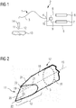
- FIG. 2 shows a perspective view of the scalpel end 12 of the optical scalpel 1.
- the scalpel end 12 is thereby by a wedge-shaped taper formed of the light guide 3.
- the optical waveguide 3 extends along a longitudinal axis 15.
- An outer side 16 of the optical waveguide 3 has a cylindrical basic shape 17 along a longitudinal axis 15.
- the basic shape 17 has, in particular, an at least approximately circular cross-section 18 FIG. 2 shown only by way of example, two-sided processing of the light guide 3 can already be formed a correspondingly advantageous to use scalpel 2.
- two wedge surfaces 19 are formed, which intersect in a pointed front edge 20.
- the wedge surfaces 19 are bounded in each case by a side edge 21 which runs at least approximately parabolically and delimits the respective wedge surface 19 from the outside 16.
- the front edge 20 extends over the entire cross section 18 of the light guide 3. At the two outer ends of the front edge 20 forms the front edge 20 with the side edges 21 corners 22. The corners 22 are thus on the outside 16 of the light guide 3. At least one of Corners 22 is formed at the distal end 11 of the light guide 3 Thomasfase 23, for example, where the side edges 21 are marked with the dashed lines circles. There, the side edges 21 exert the function of a cutting edge.
- FIGS. 3 and 4 another embodiment is shown.
- the distal end 11 of the optical fiber 3 has been processed only from one side.
- the original optical waveguide 3 the cylindrical basic shape 17, so its distal end 11 is bounded by the outer side 16 and a circular end face 24.
- a bevel 25 is formed at its distal end 11.
- the chamfering surface 25 is limited to the outer side 16 by side edges 26 and the end face 24 through the front edge 27.
- the end face 24 no longer has a circular outline, but has the shape of a circle segment which is limited to the outside 16 through an outer edge 28.
- a corner 22 is formed at that point in which the end face 24 of the light guide 3, the outer side 16 of the light guide 3 and the aforementioned bevel 25 meet.
- a scalpel end 12 according to the invention is formed at the distal end 11 of the light guide 3.
- FIG. 5 illustrates the operation of the optical scalpel 1 using an embodiment with two Abschrägungs vom 25, whose projected to the cross section 18 normals occupy an angle less than 180 °.
- Scalpel ending 12 has been formed, for example, by a double machining of the distal end 11 of an originally cylindrical optical waveguide 3.
- two chamfer surfaces 25 each having an associated front edge 20, an approximately circular segment-shaped outline of the end face 24 and three corners 22 as shown in particular arise FIG. 6 is recognizable.
- the laser radiation 8 acts as a primary tool, the laser radiation 8.
- the longitudinal axis 15 of the scalpel end 12 is aligned normal to the surface of the fabric 13, so that the end face 24 is parallel to the surface of the fabric 13.
- the end face 24 is further guided over the surface of the fabric 13 at a distance d.
- the dimensions of a focal spot 29 formed by the laser radiation 8 depend, on the one hand, on the dimensions of the end face 24 and on the other hand on the distance d of the end face 24 to the surface of the fabric 13. The reason for this is the known divergence of the laser radiation 8, which increases the focal spot 29 with increasing distance d.
- the beam exit occurs, as shown, over the entire end face 24.
- FIG. 5 results in a so-called coagulation zone 30, which includes both the cutting base 31 and the cutting edges 32.
- coagulation zone 30 includes both the cutting base 31 and the cutting edges 32.
- Karbonisationszone 33 which by selecting adjustment parameters of Processing light source 6 also can not occur.
- the tissue 13 located there can be removed by the laser radiation 8.
- a wedge-shaped Thomasfase 23 formed at the distal end 11 of the optical waveguide 3 is formed.
- wedge-shaped means any kind of a tapered to Thomasfase 23 shape.
- the size of the focal spot 29 also changes. In this way, a selection with regard to the focusing on the area to be treated can also be made.
- the optical scalpel 1 according to the invention thus also makes it possible to use the mechanical cutting action of the scalpel end 12. This thus permits a particularly advantageous use of the optical scalpel 1 according to the invention, in particular for surgical applications in which, on the one hand, a mechanical separation of tissue 13 is preferred and, on the other hand, immediate coagulation (coagulation) is desired.
- FIG. 7 Figure 1 illustrates a situation in which the aforementioned mechanical cutting action is utilized to adequately separate the fabric 13.
- a preferred cutting direction is marked with S.
- the scalpel end 12 is thus designed so that a mechanical cutting property, similar to that of a classical scalpel is achieved.
- the laser radiation 8 predominantly exits via the end face 24 and coagulates directly behind the cut through the chamfer 23 the bleeding of the wound.
- the laser radiation 8 and the heating of the scalpel end 12 by means of the laser radiation 8 is not only used for cauterization or coagulation (coagulation) of the blood emerging during cutting, so that only the cut edges in the tissue 13 are coagulated. Rather, the incision wound is completely coagulated even if it comes to a gaping incision gap and the cutting base 31 widened. The resulting surface is sufficiently coagulated when using the device described herein.
- the marking light 9 as well as the laser radiation 8 can predominantly exit via the end face 24 and thereby reliably mark the treatment location.
- the scalpel end 12, as has already been described in connection with Figure 5, as well as from a distance d from a tissue 13 can be used without contact as an irradiation applicator (for example for point and area coagulation or for heating a defined body area).
- an irradiation applicator for example for point and area coagulation or for heating a defined body area.
- the thus executed light guide 3 with the scalpel end 12 can also be produced inexpensively and has a simple structure by which energy losses are avoided by coupling with other materials.
- a light guide 3 has the circular cross-section 18.
- a polygonal cross-section 34 At an arbitrary distance from the distal end 11 of the light guide 3 and its end face 24, the polygonal cross section 34 of the scalpel end 12 merges into the, for example circular, cross section 18 of the light guide 3.
- the at least one light guide 3 has a constant polygonal cross-section 34 over its entire length.
- At least one corner 22 of the polygonal cross-section 34 forms a wedge-shaped cutting chamfer 23, which lies at least approximately in the direction of the longitudinal extension of the optical waveguide 3.
- the term "wedge-shaped” is understood to mean any type of tapered shape towards the chamfer 23.
- a form already preselected for the light guide 3 can be used for the scalpel end 12.
- An aforementioned additional processing of that area through which the scalpel end 12 is formed is not necessary.
- Such an embodiment further allows a shortening of the light guide 3, in particular at its second end, without the geometry described above being changed. This can be done, for example, during a surgical procedure, with a short interruption of the procedure.
- the shortened second end of the light guide 3 can also be used as a scalpel end 12, with the advantages mentioned above.
- the end face 24 of the scalpel end 12 is configured such that at least two wedge-shaped Thomasfasen 23 are formed with at least approximately the same or different wedge angle 35.
- the respective wedge angle 35 can be used on the scalpel end 12, for example for different methods.
- a polygonal cross-section 34 could also be designed such that a double chamfer 23 forms, in which two identical or different wedge angles 35 interact with the fabric 13.
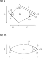
- FIG. 9 shows an embodiment whose end face 24 has a deltoid-shaped cross-section.
- FIG. 9 shows an embodiment whose end face 24 has a deltoid-shaped cross-section.
- wedge angle 35 of a wedge-shaped chamfer 23 is advantageously a range between 5 ° and 120 °, in particular between 25 ° and 50 ° into consideration. As can be appreciated, the appropriate selection of the wedge angle 35 assists in the aforementioned mechanical cutting action.
- the end faces 24 are each aligned at right angles to the longitudinal axis 15.
- the end faces 24 may be aligned so that the laser radiation 8 and the marker light 9 are broken when passing through the end face 24 to the chamfer 23 in order to achieve that the coagulation zone 30 comes closer to the scalpel end 12 to rest.
- angles of inclination of the end face 24 to the longitudinal axis 15 in the range of 45 ° to 90 ° are conceivable.
- the end face 24 but occupy an angle between 80 ° and 90 ° to the longitudinal axis 15.
- a surgical instrument based on a light guide 3 is formed.
- this can also be optionally used as a cautery.
- the simple construction allows a cost-effective production.
- the structure of the invention reduces Einkoppellage and cleaning and sterilization effort.
Landscapes
- Health & Medical Sciences (AREA)
- Surgery (AREA)
- Physics & Mathematics (AREA)
- Life Sciences & Earth Sciences (AREA)
- Engineering & Computer Science (AREA)
- Medical Informatics (AREA)
- Nuclear Medicine, Radiotherapy & Molecular Imaging (AREA)
- Electromagnetism (AREA)
- Optics & Photonics (AREA)
- Biomedical Technology (AREA)
- Heart & Thoracic Surgery (AREA)
- Otolaryngology (AREA)
- Molecular Biology (AREA)
- Animal Behavior & Ethology (AREA)
- General Health & Medical Sciences (AREA)
- Public Health (AREA)
- Veterinary Medicine (AREA)
- Laser Surgery Devices (AREA)
Applications Claiming Priority (1)
| Application Number | Priority Date | Filing Date | Title |
|---|---|---|---|
| DE102016119360.7A DE102016119360A1 (de) | 2016-10-11 | 2016-10-11 | Optisches Skalpell |
Publications (2)
| Publication Number | Publication Date |
|---|---|
| EP3308734A1 true EP3308734A1 (fr) | 2018-04-18 |
| EP3308734B1 EP3308734B1 (fr) | 2022-04-27 |
Family
ID=60119851
Family Applications (1)
| Application Number | Title | Priority Date | Filing Date |
|---|---|---|---|
| EP17195980.2A Active EP3308734B1 (fr) | 2016-10-11 | 2017-10-11 | Scalpel optique et dispositif de coupe chirurgical |
Country Status (2)
| Country | Link |
|---|---|
| EP (1) | EP3308734B1 (fr) |
| DE (1) | DE102016119360A1 (fr) |
Citations (6)
| Publication number | Priority date | Publication date | Assignee | Title |
|---|---|---|---|---|
| DE19803720A1 (de) * | 1997-01-31 | 1998-08-13 | Shinji Kokubu | Handstück für einen medizinischen Laser |
| WO2001087176A1 (fr) * | 2000-05-15 | 2001-11-22 | Clinicon Corporation | Systeme et procede chirurgical optique |
| US6673065B1 (en) * | 2000-07-31 | 2004-01-06 | Brookhaven Science Associates | Slender tip laser scalpel |
| DE102011122209A1 (de) * | 2011-12-23 | 2013-06-27 | Carl Zeiss Meditec Ag | Vorrichtung zur Homogenisierung eines Laserstrahlprofils |
| US20140180264A1 (en) * | 2012-12-21 | 2014-06-26 | Alcon Research, Ltd. | Grin fiber multi-spot laser probe |
| EP3067005A1 (fr) * | 2015-03-13 | 2016-09-14 | Max-Planck-Gesellschaft zur Förderung der Wissenschaften e.V. | Appareil de chirurgie laser pour chirurgie laser par contact |
Family Cites Families (3)
| Publication number | Priority date | Publication date | Assignee | Title |
|---|---|---|---|---|
| DE3840609A1 (de) | 1988-12-02 | 1990-06-07 | Maier Kg Andreas | Laserskalpell |
| DE102004007120B3 (de) * | 2004-02-12 | 2005-10-27 | Martin Pfeil Trawid-Gmbh | Laser-Skalpell |
| DE102009011587A1 (de) | 2009-03-06 | 2010-09-16 | A.R.C. Laser Gmbh | Laserskalpell |
-
2016
- 2016-10-11 DE DE102016119360.7A patent/DE102016119360A1/de not_active Withdrawn
-
2017
- 2017-10-11 EP EP17195980.2A patent/EP3308734B1/fr active Active
Patent Citations (6)
| Publication number | Priority date | Publication date | Assignee | Title |
|---|---|---|---|---|
| DE19803720A1 (de) * | 1997-01-31 | 1998-08-13 | Shinji Kokubu | Handstück für einen medizinischen Laser |
| WO2001087176A1 (fr) * | 2000-05-15 | 2001-11-22 | Clinicon Corporation | Systeme et procede chirurgical optique |
| US6673065B1 (en) * | 2000-07-31 | 2004-01-06 | Brookhaven Science Associates | Slender tip laser scalpel |
| DE102011122209A1 (de) * | 2011-12-23 | 2013-06-27 | Carl Zeiss Meditec Ag | Vorrichtung zur Homogenisierung eines Laserstrahlprofils |
| US20140180264A1 (en) * | 2012-12-21 | 2014-06-26 | Alcon Research, Ltd. | Grin fiber multi-spot laser probe |
| EP3067005A1 (fr) * | 2015-03-13 | 2016-09-14 | Max-Planck-Gesellschaft zur Förderung der Wissenschaften e.V. | Appareil de chirurgie laser pour chirurgie laser par contact |
Also Published As
| Publication number | Publication date |
|---|---|
| DE102016119360A1 (de) | 2018-04-12 |
| EP3308734B1 (fr) | 2022-04-27 |
Similar Documents
| Publication | Publication Date | Title |
|---|---|---|
| DE3686621T2 (de) | Infrarot laser-kathetergeraet. | |
| DE69514262T2 (de) | Katheter mit Lichtleitfaser | |
| DE19836649C2 (de) | Medizinisches Handstück | |
| DE69229128T2 (de) | Medizinische vorrichtung | |
| DE4228993C2 (de) | Chirurgisches Laser-Gerät | |
| DE68918068T2 (de) | Vorrichtung zum Schneiden oder Verdampfen von Material und verschiedenen Stoffen unter Anwendung der Laserwirkung. | |
| DE3242612C2 (de) | Laserstrahlvorrichtung | |
| DE19636265A1 (de) | Laserinstrument | |
| DE102006046370A1 (de) | Vorrichtung und Verfahren zur Materialverarbeitung unter Verwendung eines transparenten Kontaktelements | |
| DE69231402T2 (de) | Chirurgische lasersonde | |
| EP3265013B1 (fr) | Laser dentaire pour le traitement des tissus mous | |
| AT410055B (de) | Laserskalpell | |
| WO2018224210A1 (fr) | Dispositif de positionnement destiné à positionner une fibre conductrice de lumière dans un orifice d'étalonnage | |
| EP2341863B1 (fr) | Dispositif laser multifonction | |
| EP3308734B1 (fr) | Scalpel optique et dispositif de coupe chirurgical | |
| DE112017004470T5 (de) | Monopolare elektrochirurgische klinge und elektrochirurgische klingenanordnung | |
| WO2017005830A1 (fr) | Instrument d'électrochirurgie pour la coagulation au plasma argon et procédé pour faire fonctionner cet instrument | |
| DE69530328T2 (de) | Laservorrichtung mit pulsierender emission für die medizintechnik | |
| WO2009052847A1 (fr) | Dispositif de vaporisation de tissus par rayonnement laser | |
| DE102007040337A1 (de) | Laserbehandlungsgerät | |
| DE10021278B4 (de) | Handstück zur Abstrahlung von Licht auf eine Hautfläche bei einer medizinischen oder kosmetischen Hautbehandlung | |
| EP2334464B1 (fr) | Dispositif laser multifonction | |
| EP0893100A2 (fr) | Source lumineuse pulsée | |
| EP3634326B1 (fr) | Aiguille creuse pour un instrument de chirurgie oculaire | |
| DE102022129433A1 (de) | Steuerung eines augenchirurgischen Lasers einer Behandlungsvorrichtung zur Behandlung einer Fehlsichtigkeit |
Legal Events
| Date | Code | Title | Description |
|---|---|---|---|
| PUAI | Public reference made under article 153(3) epc to a published international application that has entered the european phase |
Free format text: ORIGINAL CODE: 0009012 |
|
| STAA | Information on the status of an ep patent application or granted ep patent |
Free format text: STATUS: THE APPLICATION HAS BEEN PUBLISHED |
|
| AK | Designated contracting states |
Kind code of ref document: A1 Designated state(s): AL AT BE BG CH CY CZ DE DK EE ES FI FR GB GR HR HU IE IS IT LI LT LU LV MC MK MT NL NO PL PT RO RS SE SI SK SM TR |
|
| AX | Request for extension of the european patent |
Extension state: BA ME |
|
| RIN1 | Information on inventor provided before grant (corrected) |
Inventor name: KLAMANN, KARL |
|
| STAA | Information on the status of an ep patent application or granted ep patent |
Free format text: STATUS: REQUEST FOR EXAMINATION WAS MADE |
|
| 17P | Request for examination filed |
Effective date: 20181018 |
|
| RBV | Designated contracting states (corrected) |
Designated state(s): AL AT BE BG CH CY CZ DE DK EE ES FI FR GB GR HR HU IE IS IT LI LT LU LV MC MK MT NL NO PL PT RO RS SE SI SK SM TR |
|
| STAA | Information on the status of an ep patent application or granted ep patent |
Free format text: STATUS: EXAMINATION IS IN PROGRESS |
|
| 17Q | First examination report despatched |
Effective date: 20190924 |
|
| GRAP | Despatch of communication of intention to grant a patent |
Free format text: ORIGINAL CODE: EPIDOSNIGR1 |
|
| STAA | Information on the status of an ep patent application or granted ep patent |
Free format text: STATUS: GRANT OF PATENT IS INTENDED |
|
| RIC1 | Information provided on ipc code assigned before grant |
Ipc: A61B 18/22 20060101AFI20210528BHEP Ipc: A61B 17/3211 20060101ALN20210528BHEP Ipc: A61B 18/20 20060101ALN20210528BHEP |
|
| INTG | Intention to grant announced |
Effective date: 20210621 |
|
| GRAJ | Information related to disapproval of communication of intention to grant by the applicant or resumption of examination proceedings by the epo deleted |
Free format text: ORIGINAL CODE: EPIDOSDIGR1 |
|
| STAA | Information on the status of an ep patent application or granted ep patent |
Free format text: STATUS: EXAMINATION IS IN PROGRESS |
|
| GRAS | Grant fee paid |
Free format text: ORIGINAL CODE: EPIDOSNIGR3 |
|
| STAA | Information on the status of an ep patent application or granted ep patent |
Free format text: STATUS: GRANT OF PATENT IS INTENDED |
|
| INTC | Intention to grant announced (deleted) | ||
| GRAP | Despatch of communication of intention to grant a patent |
Free format text: ORIGINAL CODE: EPIDOSNIGR1 |
|
| RIC1 | Information provided on ipc code assigned before grant |
Ipc: A61B 18/20 20060101ALN20211117BHEP Ipc: A61B 17/3211 20060101ALN20211117BHEP Ipc: A61B 18/22 20060101AFI20211117BHEP |
|
| INTG | Intention to grant announced |
Effective date: 20211203 |
|
| GRAA | (expected) grant |
Free format text: ORIGINAL CODE: 0009210 |
|
| STAA | Information on the status of an ep patent application or granted ep patent |
Free format text: STATUS: THE PATENT HAS BEEN GRANTED |
|
| AK | Designated contracting states |
Kind code of ref document: B1 Designated state(s): AL AT BE BG CH CY CZ DE DK EE ES FI FR GB GR HR HU IE IS IT LI LT LU LV MC MK MT NL NO PL PT RO RS SE SI SK SM TR |
|
| REG | Reference to a national code |
Ref country code: GB Ref legal event code: FG4D Free format text: NOT ENGLISH |
|
| REG | Reference to a national code |
Ref country code: CH Ref legal event code: EP |
|
| REG | Reference to a national code |
Ref country code: DE Ref legal event code: R096 Ref document number: 502017013063 Country of ref document: DE |
|
| REG | Reference to a national code |
Ref country code: AT Ref legal event code: REF Ref document number: 1486339 Country of ref document: AT Kind code of ref document: T Effective date: 20220515 |
|
| REG | Reference to a national code |
Ref country code: IE Ref legal event code: FG4D Free format text: LANGUAGE OF EP DOCUMENT: GERMAN |
|
| REG | Reference to a national code |
Ref country code: NL Ref legal event code: FP |
|
| REG | Reference to a national code |
Ref country code: LT Ref legal event code: MG9D |
|
| PG25 | Lapsed in a contracting state [announced via postgrant information from national office to epo] |
Ref country code: SE Free format text: LAPSE BECAUSE OF FAILURE TO SUBMIT A TRANSLATION OF THE DESCRIPTION OR TO PAY THE FEE WITHIN THE PRESCRIBED TIME-LIMIT Effective date: 20220427 Ref country code: PT Free format text: LAPSE BECAUSE OF FAILURE TO SUBMIT A TRANSLATION OF THE DESCRIPTION OR TO PAY THE FEE WITHIN THE PRESCRIBED TIME-LIMIT Effective date: 20220829 Ref country code: NO Free format text: LAPSE BECAUSE OF FAILURE TO SUBMIT A TRANSLATION OF THE DESCRIPTION OR TO PAY THE FEE WITHIN THE PRESCRIBED TIME-LIMIT Effective date: 20220727 Ref country code: LT Free format text: LAPSE BECAUSE OF FAILURE TO SUBMIT A TRANSLATION OF THE DESCRIPTION OR TO PAY THE FEE WITHIN THE PRESCRIBED TIME-LIMIT Effective date: 20220427 Ref country code: HR Free format text: LAPSE BECAUSE OF FAILURE TO SUBMIT A TRANSLATION OF THE DESCRIPTION OR TO PAY THE FEE WITHIN THE PRESCRIBED TIME-LIMIT Effective date: 20220427 Ref country code: GR Free format text: LAPSE BECAUSE OF FAILURE TO SUBMIT A TRANSLATION OF THE DESCRIPTION OR TO PAY THE FEE WITHIN THE PRESCRIBED TIME-LIMIT Effective date: 20220728 Ref country code: FI Free format text: LAPSE BECAUSE OF FAILURE TO SUBMIT A TRANSLATION OF THE DESCRIPTION OR TO PAY THE FEE WITHIN THE PRESCRIBED TIME-LIMIT Effective date: 20220427 Ref country code: BG Free format text: LAPSE BECAUSE OF FAILURE TO SUBMIT A TRANSLATION OF THE DESCRIPTION OR TO PAY THE FEE WITHIN THE PRESCRIBED TIME-LIMIT Effective date: 20220727 |
|
| PG25 | Lapsed in a contracting state [announced via postgrant information from national office to epo] |
Ref country code: RS Free format text: LAPSE BECAUSE OF FAILURE TO SUBMIT A TRANSLATION OF THE DESCRIPTION OR TO PAY THE FEE WITHIN THE PRESCRIBED TIME-LIMIT Effective date: 20220427 Ref country code: PL Free format text: LAPSE BECAUSE OF FAILURE TO SUBMIT A TRANSLATION OF THE DESCRIPTION OR TO PAY THE FEE WITHIN THE PRESCRIBED TIME-LIMIT Effective date: 20220427 Ref country code: LV Free format text: LAPSE BECAUSE OF FAILURE TO SUBMIT A TRANSLATION OF THE DESCRIPTION OR TO PAY THE FEE WITHIN THE PRESCRIBED TIME-LIMIT Effective date: 20220427 Ref country code: IS Free format text: LAPSE BECAUSE OF FAILURE TO SUBMIT A TRANSLATION OF THE DESCRIPTION OR TO PAY THE FEE WITHIN THE PRESCRIBED TIME-LIMIT Effective date: 20220827 |
|
| REG | Reference to a national code |
Ref country code: DE Ref legal event code: R097 Ref document number: 502017013063 Country of ref document: DE |
|
| PG25 | Lapsed in a contracting state [announced via postgrant information from national office to epo] |
Ref country code: SM Free format text: LAPSE BECAUSE OF FAILURE TO SUBMIT A TRANSLATION OF THE DESCRIPTION OR TO PAY THE FEE WITHIN THE PRESCRIBED TIME-LIMIT Effective date: 20220427 Ref country code: SK Free format text: LAPSE BECAUSE OF FAILURE TO SUBMIT A TRANSLATION OF THE DESCRIPTION OR TO PAY THE FEE WITHIN THE PRESCRIBED TIME-LIMIT Effective date: 20220427 Ref country code: RO Free format text: LAPSE BECAUSE OF FAILURE TO SUBMIT A TRANSLATION OF THE DESCRIPTION OR TO PAY THE FEE WITHIN THE PRESCRIBED TIME-LIMIT Effective date: 20220427 Ref country code: ES Free format text: LAPSE BECAUSE OF FAILURE TO SUBMIT A TRANSLATION OF THE DESCRIPTION OR TO PAY THE FEE WITHIN THE PRESCRIBED TIME-LIMIT Effective date: 20220427 Ref country code: EE Free format text: LAPSE BECAUSE OF FAILURE TO SUBMIT A TRANSLATION OF THE DESCRIPTION OR TO PAY THE FEE WITHIN THE PRESCRIBED TIME-LIMIT Effective date: 20220427 Ref country code: DK Free format text: LAPSE BECAUSE OF FAILURE TO SUBMIT A TRANSLATION OF THE DESCRIPTION OR TO PAY THE FEE WITHIN THE PRESCRIBED TIME-LIMIT Effective date: 20220427 Ref country code: CZ Free format text: LAPSE BECAUSE OF FAILURE TO SUBMIT A TRANSLATION OF THE DESCRIPTION OR TO PAY THE FEE WITHIN THE PRESCRIBED TIME-LIMIT Effective date: 20220427 |
|
| PLBE | No opposition filed within time limit |
Free format text: ORIGINAL CODE: 0009261 |
|
| STAA | Information on the status of an ep patent application or granted ep patent |
Free format text: STATUS: NO OPPOSITION FILED WITHIN TIME LIMIT |
|
| PG25 | Lapsed in a contracting state [announced via postgrant information from national office to epo] |
Ref country code: AL Free format text: LAPSE BECAUSE OF FAILURE TO SUBMIT A TRANSLATION OF THE DESCRIPTION OR TO PAY THE FEE WITHIN THE PRESCRIBED TIME-LIMIT Effective date: 20220427 |
|
| 26N | No opposition filed |
Effective date: 20230130 |
|
| PG25 | Lapsed in a contracting state [announced via postgrant information from national office to epo] |
Ref country code: SI Free format text: LAPSE BECAUSE OF FAILURE TO SUBMIT A TRANSLATION OF THE DESCRIPTION OR TO PAY THE FEE WITHIN THE PRESCRIBED TIME-LIMIT Effective date: 20220427 Ref country code: MC Free format text: LAPSE BECAUSE OF FAILURE TO SUBMIT A TRANSLATION OF THE DESCRIPTION OR TO PAY THE FEE WITHIN THE PRESCRIBED TIME-LIMIT Effective date: 20220427 |
|
| PG25 | Lapsed in a contracting state [announced via postgrant information from national office to epo] |
Ref country code: LU Free format text: LAPSE BECAUSE OF NON-PAYMENT OF DUE FEES Effective date: 20221011 |
|
| PG25 | Lapsed in a contracting state [announced via postgrant information from national office to epo] |
Ref country code: IE Free format text: LAPSE BECAUSE OF NON-PAYMENT OF DUE FEES Effective date: 20221011 |
|
| REG | Reference to a national code |
Ref country code: AT Ref legal event code: MM01 Ref document number: 1486339 Country of ref document: AT Kind code of ref document: T Effective date: 20221011 |
|
| PG25 | Lapsed in a contracting state [announced via postgrant information from national office to epo] |
Ref country code: AT Free format text: LAPSE BECAUSE OF NON-PAYMENT OF DUE FEES Effective date: 20221011 |
|
| PG25 | Lapsed in a contracting state [announced via postgrant information from national office to epo] |
Ref country code: HU Free format text: LAPSE BECAUSE OF FAILURE TO SUBMIT A TRANSLATION OF THE DESCRIPTION OR TO PAY THE FEE WITHIN THE PRESCRIBED TIME-LIMIT; INVALID AB INITIO Effective date: 20171011 |
|
| PG25 | Lapsed in a contracting state [announced via postgrant information from national office to epo] |
Ref country code: CY Free format text: LAPSE BECAUSE OF FAILURE TO SUBMIT A TRANSLATION OF THE DESCRIPTION OR TO PAY THE FEE WITHIN THE PRESCRIBED TIME-LIMIT Effective date: 20220427 |
|
| PG25 | Lapsed in a contracting state [announced via postgrant information from national office to epo] |
Ref country code: MK Free format text: LAPSE BECAUSE OF FAILURE TO SUBMIT A TRANSLATION OF THE DESCRIPTION OR TO PAY THE FEE WITHIN THE PRESCRIBED TIME-LIMIT Effective date: 20220427 |
|
| PG25 | Lapsed in a contracting state [announced via postgrant information from national office to epo] |
Ref country code: TR Free format text: LAPSE BECAUSE OF FAILURE TO SUBMIT A TRANSLATION OF THE DESCRIPTION OR TO PAY THE FEE WITHIN THE PRESCRIBED TIME-LIMIT Effective date: 20220427 |
|
| PG25 | Lapsed in a contracting state [announced via postgrant information from national office to epo] |
Ref country code: MT Free format text: LAPSE BECAUSE OF FAILURE TO SUBMIT A TRANSLATION OF THE DESCRIPTION OR TO PAY THE FEE WITHIN THE PRESCRIBED TIME-LIMIT Effective date: 20220427 |
|
| PG25 | Lapsed in a contracting state [announced via postgrant information from national office to epo] |
Ref country code: BG Free format text: LAPSE BECAUSE OF FAILURE TO SUBMIT A TRANSLATION OF THE DESCRIPTION OR TO PAY THE FEE WITHIN THE PRESCRIBED TIME-LIMIT Effective date: 20220427 |
|
| PG25 | Lapsed in a contracting state [announced via postgrant information from national office to epo] |
Ref country code: BG Free format text: LAPSE BECAUSE OF FAILURE TO SUBMIT A TRANSLATION OF THE DESCRIPTION OR TO PAY THE FEE WITHIN THE PRESCRIBED TIME-LIMIT Effective date: 20220427 |
|
| REG | Reference to a national code |
Ref country code: CH Ref legal event code: U11 Free format text: ST27 STATUS EVENT CODE: U-0-0-U10-U11 (AS PROVIDED BY THE NATIONAL OFFICE) Effective date: 20251101 |
|
| PGFP | Annual fee paid to national office [announced via postgrant information from national office to epo] |
Ref country code: NL Payment date: 20251023 Year of fee payment: 9 |
|
| PGFP | Annual fee paid to national office [announced via postgrant information from national office to epo] |
Ref country code: DE Payment date: 20251020 Year of fee payment: 9 |
|
| PGFP | Annual fee paid to national office [announced via postgrant information from national office to epo] |
Ref country code: GB Payment date: 20251024 Year of fee payment: 9 |
|
| PGFP | Annual fee paid to national office [announced via postgrant information from national office to epo] |
Ref country code: IT Payment date: 20251031 Year of fee payment: 9 |
|
| PGFP | Annual fee paid to national office [announced via postgrant information from national office to epo] |
Ref country code: FR Payment date: 20251027 Year of fee payment: 9 |
|
| PGFP | Annual fee paid to national office [announced via postgrant information from national office to epo] |
Ref country code: BE Payment date: 20251022 Year of fee payment: 9 |
|
| PGFP | Annual fee paid to national office [announced via postgrant information from national office to epo] |
Ref country code: CH Payment date: 20251101 Year of fee payment: 9 |