EP3308760B1 - Wundabdeckung und verfahren zur herstellung - Google Patents
Wundabdeckung und verfahren zur herstellung Download PDFInfo
- Publication number
- EP3308760B1 EP3308760B1 EP17198606.0A EP17198606A EP3308760B1 EP 3308760 B1 EP3308760 B1 EP 3308760B1 EP 17198606 A EP17198606 A EP 17198606A EP 3308760 B1 EP3308760 B1 EP 3308760B1
- Authority
- EP
- European Patent Office
- Prior art keywords
- web
- wound covering
- wound
- type element
- boundary surface
- Prior art date
- Legal status (The legal status is an assumption and is not a legal conclusion. Google has not performed a legal analysis and makes no representation as to the accuracy of the status listed.)
- Active
Links
Images

Classifications
-
- A—HUMAN NECESSITIES
- A61—MEDICAL OR VETERINARY SCIENCE; HYGIENE
- A61F—FILTERS IMPLANTABLE INTO BLOOD VESSELS; PROSTHESES; DEVICES PROVIDING PATENCY TO, OR PREVENTING COLLAPSING OF, TUBULAR STRUCTURES OF THE BODY, e.g. STENTS; ORTHOPAEDIC, NURSING OR CONTRACEPTIVE DEVICES; FOMENTATION; TREATMENT OR PROTECTION OF EYES OR EARS; BANDAGES, DRESSINGS OR ABSORBENT PADS; FIRST-AID KITS
- A61F13/00—Bandages or dressings; Absorbent pads
-
- A—HUMAN NECESSITIES
- A61—MEDICAL OR VETERINARY SCIENCE; HYGIENE
- A61F—FILTERS IMPLANTABLE INTO BLOOD VESSELS; PROSTHESES; DEVICES PROVIDING PATENCY TO, OR PREVENTING COLLAPSING OF, TUBULAR STRUCTURES OF THE BODY, e.g. STENTS; ORTHOPAEDIC, NURSING OR CONTRACEPTIVE DEVICES; FOMENTATION; TREATMENT OR PROTECTION OF EYES OR EARS; BANDAGES, DRESSINGS OR ABSORBENT PADS; FIRST-AID KITS
- A61F13/00—Bandages or dressings; Absorbent pads
- A61F13/00987—Apparatus or processes for manufacturing non-adhesive dressings or bandages
- A61F13/00991—Apparatus or processes for manufacturing non-adhesive dressings or bandages for treating webs, e.g. for moisturising, coating, impregnating or applying powder
- A61F13/00995—Apparatus or processes for manufacturing non-adhesive dressings or bandages for treating webs, e.g. for moisturising, coating, impregnating or applying powder for mechanical treatments
-
- A—HUMAN NECESSITIES
- A61—MEDICAL OR VETERINARY SCIENCE; HYGIENE
- A61F—FILTERS IMPLANTABLE INTO BLOOD VESSELS; PROSTHESES; DEVICES PROVIDING PATENCY TO, OR PREVENTING COLLAPSING OF, TUBULAR STRUCTURES OF THE BODY, e.g. STENTS; ORTHOPAEDIC, NURSING OR CONTRACEPTIVE DEVICES; FOMENTATION; TREATMENT OR PROTECTION OF EYES OR EARS; BANDAGES, DRESSINGS OR ABSORBENT PADS; FIRST-AID KITS
- A61F13/00—Bandages or dressings; Absorbent pads
- A61F13/02—Adhesive bandages or dressings
-
- A—HUMAN NECESSITIES
- A61—MEDICAL OR VETERINARY SCIENCE; HYGIENE
- A61F—FILTERS IMPLANTABLE INTO BLOOD VESSELS; PROSTHESES; DEVICES PROVIDING PATENCY TO, OR PREVENTING COLLAPSING OF, TUBULAR STRUCTURES OF THE BODY, e.g. STENTS; ORTHOPAEDIC, NURSING OR CONTRACEPTIVE DEVICES; FOMENTATION; TREATMENT OR PROTECTION OF EYES OR EARS; BANDAGES, DRESSINGS OR ABSORBENT PADS; FIRST-AID KITS
- A61F13/00—Bandages or dressings; Absorbent pads
- A61F13/02—Adhesive bandages or dressings
- A61F13/0203—Adhesive bandages or dressings with fluid retention members
- A61F13/0206—Adhesive bandages or dressings with fluid retention members with absorbent fibrous layers, e.g. woven or non-woven absorbent pads or island dressings
- A61F13/0209—Adhesive bandages or dressings with fluid retention members with absorbent fibrous layers, e.g. woven or non-woven absorbent pads or island dressings comprising superabsorbent material
-
- A—HUMAN NECESSITIES
- A61—MEDICAL OR VETERINARY SCIENCE; HYGIENE
- A61F—FILTERS IMPLANTABLE INTO BLOOD VESSELS; PROSTHESES; DEVICES PROVIDING PATENCY TO, OR PREVENTING COLLAPSING OF, TUBULAR STRUCTURES OF THE BODY, e.g. STENTS; ORTHOPAEDIC, NURSING OR CONTRACEPTIVE DEVICES; FOMENTATION; TREATMENT OR PROTECTION OF EYES OR EARS; BANDAGES, DRESSINGS OR ABSORBENT PADS; FIRST-AID KITS
- A61F13/00—Bandages or dressings; Absorbent pads
- A61F13/02—Adhesive bandages or dressings
- A61F13/0203—Adhesive bandages or dressings with fluid retention members
- A61F13/022—Adhesive bandages or dressings with fluid retention members having more than one layer with different fluid retention characteristics
-
- A—HUMAN NECESSITIES
- A61—MEDICAL OR VETERINARY SCIENCE; HYGIENE
- A61F—FILTERS IMPLANTABLE INTO BLOOD VESSELS; PROSTHESES; DEVICES PROVIDING PATENCY TO, OR PREVENTING COLLAPSING OF, TUBULAR STRUCTURES OF THE BODY, e.g. STENTS; ORTHOPAEDIC, NURSING OR CONTRACEPTIVE DEVICES; FOMENTATION; TREATMENT OR PROTECTION OF EYES OR EARS; BANDAGES, DRESSINGS OR ABSORBENT PADS; FIRST-AID KITS
- A61F13/00—Bandages or dressings; Absorbent pads
- A61F13/02—Adhesive bandages or dressings
- A61F13/0203—Adhesive bandages or dressings with fluid retention members
- A61F13/0223—Adhesive bandages or dressings with fluid retention members characterized by parametric properties of the fluid retention layer, e.g. absorbency, wicking capacity, liquid distribution
-
- A—HUMAN NECESSITIES
- A61—MEDICAL OR VETERINARY SCIENCE; HYGIENE
- A61F—FILTERS IMPLANTABLE INTO BLOOD VESSELS; PROSTHESES; DEVICES PROVIDING PATENCY TO, OR PREVENTING COLLAPSING OF, TUBULAR STRUCTURES OF THE BODY, e.g. STENTS; ORTHOPAEDIC, NURSING OR CONTRACEPTIVE DEVICES; FOMENTATION; TREATMENT OR PROTECTION OF EYES OR EARS; BANDAGES, DRESSINGS OR ABSORBENT PADS; FIRST-AID KITS
- A61F13/00—Bandages or dressings; Absorbent pads
- A61F13/05—Bandages or dressings; Absorbent pads specially adapted for use with sub-pressure or over-pressure therapy, wound drainage or wound irrigation, e.g. for use with negative-pressure wound therapy [NPWT]
-
- A—HUMAN NECESSITIES
- A61—MEDICAL OR VETERINARY SCIENCE; HYGIENE
- A61M—DEVICES FOR INTRODUCING MEDIA INTO, OR ONTO, THE BODY; DEVICES FOR TRANSDUCING BODY MEDIA OR FOR TAKING MEDIA FROM THE BODY; DEVICES FOR PRODUCING OR ENDING SLEEP OR STUPOR
- A61M1/00—Suction or pumping devices for medical purposes; Devices for carrying-off, for treatment of, or for carrying-over, body-liquids; Drainage systems
- A61M1/90—Negative pressure wound therapy devices, i.e. devices for applying suction to a wound to promote healing, e.g. including a vacuum dressing
- A61M1/91—Suction aspects of the dressing
- A61M1/915—Constructional details of the pressure distribution manifold
-
- A—HUMAN NECESSITIES
- A61—MEDICAL OR VETERINARY SCIENCE; HYGIENE
- A61F—FILTERS IMPLANTABLE INTO BLOOD VESSELS; PROSTHESES; DEVICES PROVIDING PATENCY TO, OR PREVENTING COLLAPSING OF, TUBULAR STRUCTURES OF THE BODY, e.g. STENTS; ORTHOPAEDIC, NURSING OR CONTRACEPTIVE DEVICES; FOMENTATION; TREATMENT OR PROTECTION OF EYES OR EARS; BANDAGES, DRESSINGS OR ABSORBENT PADS; FIRST-AID KITS
- A61F13/00—Bandages or dressings; Absorbent pads
- A61F2013/00361—Plasters
- A61F2013/00365—Plasters use
- A61F2013/00536—Plasters use for draining or irrigating wounds
-
- A—HUMAN NECESSITIES
- A61—MEDICAL OR VETERINARY SCIENCE; HYGIENE
- A61F—FILTERS IMPLANTABLE INTO BLOOD VESSELS; PROSTHESES; DEVICES PROVIDING PATENCY TO, OR PREVENTING COLLAPSING OF, TUBULAR STRUCTURES OF THE BODY, e.g. STENTS; ORTHOPAEDIC, NURSING OR CONTRACEPTIVE DEVICES; FOMENTATION; TREATMENT OR PROTECTION OF EYES OR EARS; BANDAGES, DRESSINGS OR ABSORBENT PADS; FIRST-AID KITS
- A61F13/00—Bandages or dressings; Absorbent pads
- A61F2013/00361—Plasters
- A61F2013/00365—Plasters use
- A61F2013/0054—Plasters use for deep wounds
-
- A—HUMAN NECESSITIES
- A61—MEDICAL OR VETERINARY SCIENCE; HYGIENE
- A61M—DEVICES FOR INTRODUCING MEDIA INTO, OR ONTO, THE BODY; DEVICES FOR TRANSDUCING BODY MEDIA OR FOR TAKING MEDIA FROM THE BODY; DEVICES FOR PRODUCING OR ENDING SLEEP OR STUPOR
- A61M1/00—Suction or pumping devices for medical purposes; Devices for carrying-off, for treatment of, or for carrying-over, body-liquids; Drainage systems
- A61M1/90—Negative pressure wound therapy devices, i.e. devices for applying suction to a wound to promote healing, e.g. including a vacuum dressing
- A61M1/91—Suction aspects of the dressing
- A61M1/916—Suction aspects of the dressing specially adapted for deep wounds
Definitions
- the invention relates to a wound covering with a first web-shaped element forming a first boundary surface and a second web-shaped element forming a second boundary surface facing away from the first boundary surface and running approximately parallel thereto and connected to the first web-shaped element, and to a method for producing wound coverings according to the invention.
- Such wound coverings are required for various illnesses or traumas, particularly in the area of the open abdomen, when temporary covering of the open wound or the open abdomen is necessary. This can be necessary, for example, if several interventions are required daily in order to enable rapid access to the internal organs on the one hand and to reduce the adverse effect of exudate formation in the wound area on the other. Temporary covering can achieve a significant reduction in mortality in some indications.
- wound coverings suitable for the above-mentioned purposes basically have to meet two main requirements. Firstly, a good Exudate management in the wound area, particularly when used in an open abdomen, should be achieved, ie suction in the entire wound area or the entire abdomen. In addition, friction between the organs and the peritoneum and the wound covering should be reduced, while at the same time the open wound is well shielded from the environment. In addition, it must be ensured that no contamination gets into the open wound or the open abdominal area through the wound covering.
- WO 2007/118652 A1 describes a wound spacer grid onto which absorbent secondary dressings can be applied without adhesive and which is equipped with a large number of three-dimensional perforations to form a first smooth surface and a second surface with a rough feel.
- the downstream absorption bodies are replaceable in order to ensure satisfactory wound care over a longer period of time.
- U1 describes a bandage for wrapping around a surgically placed line from a human or animal body opening, which has at least one slit that allows the bandage to be wrapped around the respective line on the patient's body.
- the object of the invention is to provide a wound covering which enables good exudate management over the entire wound area without contaminating the wound itself.
- the formation of the drainage space creates a capillary effect between the individual web-shaped elements, which on the one hand prevents body fluids, especially exudates, from flowing out of the drainage space and on the other hand allows the body fluids to be distributed over the entire drainage area without additional measures such as the provision of additional absorbent bodies being absolutely necessary. In this way, good exudate management is possible over the entire wound area, because there are no edge areas without a capillary function that would adversely affect exudate management. are required.
- the wound covering according to the invention can be easily cut to any size or structure of wounds, especially in the abdominal cavity, and ensures the desired drainage function over the entire wound covering surface.
- the wound covering can also be designed with a smooth surface that prevents tissue and cell wound base or the surrounding organs from adhering.
- the entry of body fluids into the drainage space can be ensured when using wound coverings according to the invention by the fact that the web-shaped elements themselves are made of a liquid-permeable material.
- exudate management can be improved particularly effectively if the cross-sectional area of the channel is reduced in a plane extending perpendicular to the depth direction, starting from the web-shaped element in the direction of the opposite inner boundary surface, in particular to maintain a capillary effect that promotes the entry of body fluids into the drainage space.
- the removal of exudate from the wound area is supported and, on the other hand, backflow from the drainage space into the wound space is prevented.
- the mouths of the openings arranged in one of the web-shaped elements are arranged in a projection along the depth direction between the mouths of the openings arranged in the other web-shaped element.
- This arrangement of the openings in wound coverings according to the invention can be used with particular advantage in the case of openings formed by channels when the wound covering is used in conjunction with a negative pressure source used to suck out the exudate from the wound area, in particular the abdominal cavity, in order to prevent the overall structure from collapsing when negative pressure is applied.
- at least one channel forming an opening in a web-shaped element extends in the depth direction over 50% or more of the total depth of the drainage space.
- the mouth area of the individual openings facing the drainage space in a plane running perpendicular to the depth direction is 0.1 mm 2 or more, in particular 0.5 mm 2 or more, particularly preferably 1 mm 2 or more.
- the desired capillary effect is achieved according to the invention while avoiding a backflow of liquid from the drainage space into the wound space, because the mouth area of the openings is 5 mm 2 or less, in particular 4 mm 2 or less, particularly preferably 3 mm 2 or less.
- the channels forming the openings in the web-shaped elements can be formed by perforations in the web-shaped elements.
- the channel wall is curved at least in sections in a cutting plane extending parallel to the depth direction and merges continuously into the boundary surface of the web-shaped element.
- the web-shaped elements are connected via point-shaped fastening areas, preferably designed in a grid arrangement, while simultaneously ensuring the drainage space that produces the drainage effect.
- the fastening can be done by welding, gluing or other fixed types of connection.
- the connection should not hinder the removal of exudates, but rather support it.
- the individual fastening areas have an area of 5 mm 2 or less, in particular 3 mm 2 or less, particularly preferably 2 mm 2 or less, in a cutting plane extending perpendicular to the depth direction, wherein the distance between individual fastening areas or individual grid points of the fastening areas designed in a grid arrangement is 2 mm or more, in particular 3 mm or more, particularly preferably 5 mm or more.
- a material bridge can be formed in the fastening areas that connects the inner boundary surfaces of the web-shaped elements to one another.
- the distance between the inner boundary surfaces of the web-shaped elements in the inventive Wound coverings 5 mm or less, preferably 4 mm or less, particularly preferably 2 mm or less.
- the distribution of the exudates over the entire surface of the wound covering can be ensured by utilizing the capillary effect in the drainage space if the distance between the inner boundary surfaces of the web-shaped elements is 0.05 mm or more, in particular 0.1 mm or more, particularly preferably 0.3 mm or more.
- At least one web-shaped element has a preferably perforated plastic film and is in particular formed overall in the form of a perforated plastic film.
- the wound covering according to the invention can be used with particular advantage in combination with negative pressure therapy for wound care.
- the wound covering according to the invention is used as a wound dressing or as a direct interface between the wound base (tissue, cells) and the wound filler or the area of exudate removal.
- the wound covering according to the invention is particularly suitable for use on wounds in the open abdomen.
- the wound covering according to the invention is placed over the organs (intestines) in the entire abdominal cavity, whereby the wound covering offers a drainage function and a very smooth surface in order to prevent adhesion or friction of the tissue and film.
- the wound covering according to the invention can be anatomically pre-shaped, but can also be cut to size to suit specific conditions.
- a filling medium such as gauze or foam is filled onto the wound covering according to the invention until the area is covered up to the skin border.
- a tubular wound drain can be inserted into this wound filler if necessary.
- the tube used to drain the exudates or for wound drainage is led out of the abdominal cavity and connected to a negative pressure source, which can be provided by a pump or, in the hospital, by a central home supply.
- the wound is sealed occlusively with an adhesive film.
- the negative pressure source can then be used to transport the exudate from the entire abdominal cavity using the wound covering according to the invention, thereby achieving good exudate management.
- the film for the occlusive covering of the wound is responsible for shielding the internal organs from the outside world and regulates moisture and temperature. It is also a barrier against bacteria, viruses and germs, comparable to the skin.
- a method for producing wound coverings according to the invention is essentially characterized in that a web-shaped material is perforated, for example using a punching roller, to form funnel-shaped openings, two perforated Sections of the web-shaped material are placed one on top of the other with the funnel openings facing each other and then connected to each other, for example by means of a spot welding process, as precisely defined in claim 11.
- the desired distance between the inner boundary surfaces can be ensured by the depth of the funnel-shaped openings.
- the perforation process can only be carried out with limited accuracy, so that even if some funnel openings are in contact with the opposite inner boundary surface of the opposite web-shaped element, other funnel openings still open freely into the drainage space.
- At least one material web can have a hydrophilic or hydrophobic finish. Furthermore, the application of swellable materials is also considered.
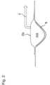
- the wound covering shown comprises a first web-shaped element 10 having an outer boundary surface 12 and a second web-shaped element 20 having an outer boundary surface 22.
- a drainage space 40 is formed between an inner boundary surface 14 of the first web-shaped element 10 facing the second web-shaped element 20 and an inner boundary surface 24 of the second web-shaped element 20 facing the first web-shaped element 10.
- the depth of the drainage space 40 in a direction perpendicular to the main surfaces of the web-shaped elements 10 and 20 is between 0.1 and 4 mm in the embodiment of the invention shown in the drawing.
- the first web-shaped element 10 has a plurality of channel-shaped perforations 16 arranged in a grid.
- the channel walls of the channels 16 are curved in a cutting plane running parallel to the depth direction and merge smoothly into the outer boundary surface 12 of the first web-shaped element 10.
- the second web-shaped element 20 has a number of perforations 26 arranged in a grid, also channel-shaped.
- the channels 16 and 26 each extend over more than half of the total depth T of the drainage space 40.
- the channels 12 and 16 are arranged such that a projection of the channel mouths of the channels 16 in the depth direction comes to lie between the channel mouths of the channels 26.
- the conical channels 16 and 26 in the embodiment of the invention explained with reference to the drawing have a diameter of 0.2 to 1 mm.
- the web-shaped elements 10 and 20 are connected to one another via material bridges 30 arranged in a grid pattern. The distance between the inner boundary surfaces 14 and 24 is set by the material bridges 30.
- the connecting areas 30 can be implemented by welding, gluing or other fixed types of connection.
- the web-shaped elements 10 and 20 can be implemented in the form of plastic films. At least one web-shaped element (10, 20) has a preferably perforated plastic film.
- both synthetic plastics such as PE, PP, PET, polyurethane (PUR), Teflon (PTFE) and films based on biological plastics or renewable plastics such as polyhydroxybutyrate (PHB), polylactate (PLA), polylactic acid, raw materials based on cellulose (CMC), etc.
- PUR polyurethane
- PTFE Teflon
- films based on biological plastics or renewable plastics such as polyhydroxybutyrate (PHB), polylactate (PLA), polylactic acid, raw materials based on cellulose (CMC), etc.
- PHB polyhydroxybutyrate
- PLA polylactate
- polylactic acid raw materials based on cellulose
- CMC raw materials based on cellulose
- the structure of the perforated material webs can be produced using a non-woven manufacturing process. Synthetic and natural (e.g. silk, cotton) fibers, as well as inorganic fibers (glass ceramic%) or metal (silver fibers) can be used to produce the non-wovens or fabrics.
- the material webs 10, 20 or the drainage space 40 are equipped with an antibacterial or bacteriostatic layer.
- the antibacterial or bacteriostatic effect can be achieved, for example, by PHMB, silver, chlorhexidine, etc.
- the wound covering 2 is placed on the wound bed, the wound is then filled with a filling material, such as foam, gauze or the like, and covered with an occlusive film 50.
- the occlusive film 50 is penetrated by an exudate line 6, which can be connected to a negative pressure source to suck the exudate out of the wound space.
Landscapes
- Health & Medical Sciences (AREA)
- Heart & Thoracic Surgery (AREA)
- Engineering & Computer Science (AREA)
- Public Health (AREA)
- Vascular Medicine (AREA)
- Life Sciences & Earth Sciences (AREA)
- Animal Behavior & Ethology (AREA)
- General Health & Medical Sciences (AREA)
- Biomedical Technology (AREA)
- Veterinary Medicine (AREA)
- Anesthesiology (AREA)
- Hematology (AREA)
- Manufacturing & Machinery (AREA)
- Media Introduction/Drainage Providing Device (AREA)
- Materials For Medical Uses (AREA)
- External Artificial Organs (AREA)
Description
- Die Erfindung betrifft eine Wundabdeckung mit einem eine erste Begrenzungsfläche bildenden ersten bahnförmigen Element und einem eine der ersten Begrenzungsfläche abgewandte und etwa parallel dazu verlaufende zweite Begrenzungsfläche bildenden und mit dem ersten bahnförmigen Element verbundenen zweiten bahnförmigen Element und ein Verfahren zum Herstellen erfindungsgemäßer Wundabdeckungen.
- Derartige Wundabdeckungen werden bei verschiedenartigen Krankheitsbildern bzw. Traumata, insbes. im Bereich des offenen Abdomens benötigt, wenn eine temporäre Abdeckung der offenen Wunde bzw. des offenen Abdomens notwendig ist. Das kann bspw. notwendig sein, wenn mehrere Eingriffe täglich erforderlich sind, um einerseits einen schnellen Zugang zu den inneren Organen zu ermöglichen und andererseits einen nachteilhaften Einfluß der Exsudatbildung im Wundbereich zu vermindern. Durch eine temporäre Abdeckung kann ein deutlicher Rückgang der Mortalität bei einigen Indikationen erreicht werden.
- Als für die genannten Einsatzzwecke geeignete Wundabdeckungen werden grundsätzlich aus medizinischer Sicht zwei Hauptanforderungen gestellt. Zum einen muß ein gutes Exsudatmanagement im Wundbereich, insbes. bei Einsatz im offenen Abdomen, erreicht werden, d. h. eine Absaugung im gesamten Wundbereich bzw. im gesamten Abdomen. Darüber hinaus sollte eine Friktionsminderung zwischen Organen und Bauchfell und der Wundabdeckung erreicht werden, während gleichzeitig die offene Wunde von der Umwelt gut abgeschirmt ist. Darüber hinaus muß sichergestellt werden, daß durch die Wundabdeckung keine Verunreinigungen in die offene Wunde bzw. den offenen Abdominalbereich gelangen.
- In der
EP 0 261 167 B1 ist eine flüssigkeitsdurchlässige und für den direkten Kontakt mit dem Wundgrund vorgesehene Wundabdeckung beschrieben, welche eine hydrophobe Schicht aufweist, um das Anhaften der Wundabdeckung am Wundbereich und eine dadurch ggf. verursachte Verunreinigung der Wunde zu verhindern. Mit der in dieser Schrift beschriebenen Wundabdeckung kann jedoch kein zufriedenstellendes Exsudatmanagement im Wundbereich erhalten werden. - Zur Verbesserung des Exsudatmanagements im Wundbereich wird in der
US 7,381,859 B2 eine Wundabdeckung vorgeschlagen, bei der zwischen zwei flüssigkeitsdurchlässigen, folienartigen, bahnförmigen Elementen, die in Form von Kunststofffilmen ausgeführt sein können, eine schaumartige Schicht aufgenommen ist, in der Exsudate absorbiert werden können. Bei der aus dieser Schrift bekannten Wundabdeckung hat es sich jedoch als problematisch erwiesen, daß in Randbereichen der Wundabdeckung keine zufriedenstellende Absaugung von Exsudaten erfolgen kann, so daß es in diesen Randbereichen zu Komplikationen bei der Wundversorgung kommt. - In der
WO 2007/118652 A1 ist ein Wunddistanzgitter beschrieben, auf das saugfähige Sekundärverbände kleblos auflegbar sind und welches zur Bildung einer ersten glatten Oberfläche und einer zweiten Oberfläche mit einem rauhen Griff mit einer Vielzahl von dreidimensionalen Perforationen ausgestattet ist. Bei Einsatz dieser bekannten Wundabdeckung sind die nachgeschalteten Absorptionskörper auswechselbar, um so über einen längeren Zeitraum eine zufriedenstellende Wundversorgung zu gewährleisten. Allerdings hat es sich auch bei Einsatz der in der genannten Schrift beschriebenen Wundabdeckungssysteme als problematisch erwiesen, daß ein zufriedenstellendes Exsudatmanagement über den gesamten Wundbereich, insbes. im Abdominalbereich, nicht erreichbar ist. - In der
US 4,341,217 ist eine Binde mit einem in einer äußeren Hülle aufgenommenen Absorptionskörper angegeben, bei dem die äußere Hülle kanalförmige Öffnungen aufweist. In derDE 10 2006 017 194 ist ein Primärverband zur Wundabdeckung unter Vermeidung von Verklebungen und Adhäsion mit dem Wundexsudat mit einer Vielzahl von dreidimensionalen Perforationen beschrieben. - In der
DE 20 2006 015 547 U1 ist ein Verband zur Umlage um eine chirurgisch angelegte Leitung aus einer menschlichen oder tierischen Körperöffnung beschrieben, die wenigstens einen Schlitz aufweist, der es ermöglicht, den Verband am Körper des Patienten um die jeweilige Leitung umzulegen. - In der
DE 10 2007 049 428 A1 ist ein Wundpflegeartikel mit einer superabsorbierende Polymere aufweisenden Lage beschrieben, die in einer aus Polyesterfolie gefertigten Innenhülle untergebracht sein kann. - In der
US 2004/0030304 A1 ist ein System und ein Verfahren zum temporären Verschließen einer Wunde, insbesondere einer Abdominalwunde, beschrieben, bei dem ein Verband zum Einsatz kommt, der eine Lage aus einem porösen Schaum umfasst, welche von Lagen aus einem elastomeren Material eingeschlossen ist, die von einer Anzahl geeignet angeordneter Löcher durchsetzt sind. - Wundabdeckungen nach dem Oberbegriff des Patentanspruchs 1 sind in der
DE 10 2008 034 362 A1 angegeben. - Angesichts der vorstehend beschriebenen Probleme im Stand der Technik liegt der Erfindung die Aufgabe zugrunde, eine Wundabdeckung bereitzustellen, mit der ohne Verunreinigung der Wunde selbst ein gutes Exsudatmanagement über den gesamten Wundbereich möglich ist.
- Erfindungsgemäß wird diese Aufgabe durch die im Patentanspruch 1 angegebene Weiterbildung der bekannten Wundabdeckungen gelöst.
- Bei der erfindungsgemäßen Wundabdeckung wird durch die Bildung des Drainageraums eine kapillare Wirkung zwischen den einzelnen bahnförmigen Elementen erreicht, mit der einerseits ein Abfließen von Körperflüssigkeiten, insbes. Exsudaten, aus dem Drainageraum verhindert und andererseits eine Verteilung der Körperflüssigkeiten über die gesamte Drainagefläche möglich ist, ohne daß dazu zusätzliche Maßnahmen, wie etwa die Bereitstellung zusätzlicher Absorptionskörper, zwingend erforderlich sind. Auf diese Weise wird ein gutes Exsudatmanagement über den gesamten Wundbereich ermöglicht, weil auch keine das Exsudatmanagement nachteilhaft beeinflussenden Randbereiche ohne Kapillarfunktion erforderlich sind. Die erfindungsgemäße Wundabdeckung läßt sich problemfrei auf jede Größe bzw. jede Struktur von Wunden, im besonderen im Bauchraum, zuschneiden und gewährleistet über die gesamte Wundabdeckungsfläche die gewünschte Drainagefunktion. Dabei kann die Wundabdeckung auch mit einer glatten Oberfläche ausgeführt sein, die ein Anhaften von Geweben und Zellwundgrund bzw. bei den umliegenden Organen verhindert. Der Eintritt von Körperflüssigkeiten in den Drainageraum kann bei Einsatz erfindungsgemäßer Wundabdeckungen bereits dadurch sichergestellt werden, daß die bahnförmigen Elemente selbst aus einem flüssigkeitsdurchlässigen Material gebildet sind.
- Im Rahmen der Erfindung ist vorgesehen, wie unter anderem in Anspruch 1 definiert, dass mindestens eines der bahnförmigen Elemente eine den Durchtritt von Körperflüssigkeiten in den Drainageraum ermöglichende Öffnung aufweist. Dabei wird die Stabilität der Gesamtstruktur erfindungsgemäßer Wundabdeckungen verbessert, weil mindestens eine Öffnung durch einen sich ausgehend von einem bahnförmigen Element in Richtung auf die gegenüberliegende innere Begrenzungsfläche des anderen bahnförmigen Elements erstreckenden und in den Drainageraum mündenden Kanal gebildet ist, dessen Kanalwand vorzugsweise einstückig mit dem bahnförmigen Element ausgeführt, insbes. durch Perforation des bahnförmigen Elements, gebildet ist.
- Im Rahmen der Erfindung kann das Exsudatmanagement besonders wirkungsvoll verbessert werden, wenn sich die Querschnittsfläche des Kanals in einer sich senkrecht zur Tiefenrichtung erstreckenden Ebene ausgehend von dem bahnförmigen Element in Richtung auf die gegenüberliegende innere Begrenzungsfläche, insbes. zum Erhalt einer den Eintritt von Körperflüssigkeiten in den Drainageraum begünstigenden kapillaren Wirkung, verringert. Auf diese Art und Weise wird einerseits der Abtransport von Exsudat aus dem Wundbereich unterstützt und andererseits ein Zurückfließen aus dem Drainageraum in den Wundraum verhindert.
- Im Hinblick auf die gewünschte Gesamtstabilität erfindungsgemäßer Wundabdeckungen ist erfindungsgemäß vorgesehen, dass die Mündungen der in einem der bahnförmigen Elemente angeordneten Öffnungen in einer Projektion längs der Tiefenrichtung zwischen den Mündungen der in dem anderen bahnförmigen Element angeordneten Öffnungen angeordnet sind.
- Diese Anordnung der Öffnungen in erfindungsgemäßen Wundabdeckungen kann mit besonderem Vorteil bei durch Kanäle gebildeten Öffnungen eingesetzt werden, wenn die Wundabdeckung in Verbindung mit einer zum Absaugen des Exsudats aus dem Wundbereich, insbes. Bauchraum, eingesetzten Unterdruckquelle verwendet wird, um so ein Kollabieren der Gesamtstruktur bei Anlegen von Unterdruck zu verhindern. In diesem Zusammenhang ist erfindungsgemäß vorgesehen, dass sich mindestens ein eine Öffnung in einem bahnförmigen Element bildender Kanal in Tiefenrichtung über 50 % oder mehr der gesamten Tiefe des Drainageraums erstreckt.
- Zur Sicherstellung der gewünschten Durchlässigkeit der bahnförmigen Elemente hat es sich als zweckmäßig erwiesen, wenn die dem Drainageraum zugewandte Mündungsfläche der einzelnen Öffnungen in einer senkrecht zur Tiefenrichtung verlaufenden Ebene 0,1 mm2 oder mehr, insbes. 0,5 mm2 oder mehr, besonders bevorzugt 1 mm2 oder mehr, beträgt. Die gewünschte Kapillarwirkung wird erfindungsgemäß unter Vermeidung eines Rückflusses von Flüssigkeit aus dem Drainageraum in den Wundraum erreicht, weil die Mündungsfläche der Öffnungen 5 mm2 oder weniger, insbes. 4 mm2 oder weniger, besonders bevorzugt 3 mm2 oder weniger, beträgt.
- Wie vorstehend bereits erläutert, können die die Öffnungen in den bahnförmige Elemente bildenden Kanäle durch Perforationen in den bahnförmigen Elementen gebildet sein. In diesem Zusammenhang hat es sich zum Erhalt einer glatten Oberfläche, mit der ein Anhaften von Gewebe bzw. Zellen am Wundgrund bzw. bei den umliegenden Organen wirkungsvoll unterdrückt werden kann, als günstig erwiesen, wenn die Kanalwand in einer sich parallel zur Tiefenrichtung erstreckenden Schnittebene zumindest abschnittweise bogenförmig ausgeführt ist und stetig in die Begrenzungsfläche des bahnförmigen Elements übergeht. Die Verbindung der bahnförmigen Elemente erfolgt erfindungsgemäß unter gleichzeitiger Sicherstellung des die Drainagewirkung hervorbringenden Drainageraums über punktförmige und vorzugsweise in einer Rasteranordnung ausgebildete Befestigungsbereiche erfolgen. Die Befestigung kann dabei mittels Schweißen, Kleben oder anderen festen Verbindungsarten geschehen. Dabei sollte durch die Verbindung der Abtransport von Exsudaten jedoch nicht behindert, sondern unterstützt werden. In diesem Zusammenhang hat es sich als günstig erwiesen, wenn die einzelnen Befestigungsbereiche in einer sich senkrecht zur Tiefenrichtung erstreckenden Schnittebene eine Fläche von 5 mm2 oder weniger, insbes. 3 mm2 oder weniger, besonders bevorzugt 2 mm2 oder weniger, aufweisen, wobei der Abstand zwischen einzelnen Befestigungsbereichen bzw. einzelnen Rasterpunkten der in einer Rasteranordnung ausgeführten Befestigungsbereiche 2 mm oder mehr, im besonderen 3 mm oder mehr, besonders bevorzugt 5 mm oder mehr, beträgt.
- Unabhängig davon, ob die Befestigung durch Schweißen, Kleben oder andere Verbindungsarten erfolgt, kann in den Befestigungsbereichen eine die inneren Begrenzungsflächen der bahnförmigen Elemente miteinander verbindenden Materialbrücke gebildet sein. Zum Erhalt der gewünschten Kapillarwirkung im Drainageraum beträgt der Abstand zwischen den inneren Begrenzungsflächen der bahnförmigen Elemente bei erfindungsgemäßen Wundabdeckungen 5 mm oder weniger, vorzugsweise 4 mm oder weniger, besonders bevorzugt 2 mm oder weniger. Dabei kann die Verteilung der Exsudate über die Gesamtfläche der Wundabdeckung unter Ausnutzung der Kapillarwirkung im Drainageraum sichergestellt werden, wenn der Abstand zwischen den inneren Begrenzungsflächen der bahnförmigen Elemente 0,05 mm oder mehr, insbes. 0,1 mm oder mehr, besonders bevorzugt 0,3 mm oder mehr, beträgt.
- Bei erfindungsgemäßen Wundabdeckungen weist mindestens ein bahnförmiges Element eine vorzugsweise perforierte Kunststofffolie auf und ist insbes. insgesamt in Form einer perforierten Kunststofffolie gebildet.
- Die erfindungsgemäße Wundabdeckung ist mit besonderem Vorteil in Kombination mit der Unterdrucktherapie zur Wundversorgung einsetzbar. Dabei wird die erfindungsgemäße Wundabdeckung als Wundauflage bzw. als direktes Interface zwischen dem Wundgrund (Gewebe, Zellen) und dem Wundfüller bzw. dem Bereich des Exsudatabtransports eingesetzt. Mit besonderem Vorteil ist die erfindungsgemäße Wundabdeckung für den Einsatz bei Wunden im offenen Abdomen geeignet. Dabei wird die erfindungsgemäße Wundabdeckung in dem gesamten Bauchraum über die Organe (Eingeweide) gelegt, wobei die Wundabdeckung eine Drainagefunktion und eine sehr glatte Oberfläche bietet, um ein Anhaften bzw. eine Friktion von Gewebe und Folie zu verhindern. Die erfindungsgemäße Wundabdeckung kann anatomisch vorgeformt, aber auch auf spezielle Gegebenheiten zuschneidbar ausgeführt sein. Auf die erfindungsgemäße Wundabdeckung wird bei Einsatz in Kombination mit der Unterdrucktherapie ein Füllmedium wie Gaze oder Schaum aufgefüllt, bis der Bereich bis zur Hautgrenze abgedeckt ist. In diesen Wundfüller kann eine ggf. schlauchförmige Wunddrainage eingelegt werden. Der zur Ableitung der Exsudate bzw. zur Wunddrainage eingesetzte Schlauch wird aus dem Bauchraum herausgeführt und an eine Unterdruckquelle angeschlossen, die durch eine Pumpe bzw. im Krankenhaus durch eine zentrale Hausversorgung sichergestellt werden kann. Abschließend wird die Wunde okklusiv mit einer adhäsiven Folie abgedichtet. Mit der Unterdruckquelle kann dann das Exsudat aus dem gesamten Bauchraum mittels der erfindungsgemäßen Wundabdeckung abtransportiert werden, wodurch ein gutes Exsudatmanagement erreicht wird. Die Folie für die okklusive Abdeckung der Wunde ist für die Abschirmung der inneren Organe von der Außenwelt verantwortlich und regelt Feuchtigkeit und Temperatur. Ferner ist sie eine mit der Haut vergleichbare Barriere gegen Bakterien, Viren und Keime.
- Ein Verfahren zur Herstellung erfindungsgemäßer Wundabdeckungen ist im wesentlichen dadurch gekennzeichnet, daß ein bahnförmiges Material, bspw. unter Verwendung einer Stanzwalze, zur Bildung trichterförmiger Öffnungen perforiert wird, zwei perforierte Abschnitte des bahnförmigen Materials mit einander zugewandten Trichteröffnungen übereinandergelegt und anschließend bspw. mittels eines Punktschweißverfahrens miteinander verbunden werden, wie genau definiert in Anspruch 11.
- Bei diesem Verfahren kann der gewünschte Abstand zwischen den inneren Begrenzungsflächen durch die Tiefe der trichterförmigen Öffnungen sichergestellt werden. Dabei kann der Perforationsvorgang allerdings nur mit begrenzter Genauigkeit erfolgen, so daß selbst dann, wenn einige Trichteröffnungen an der gegenüberliegenden inneren Begrenzungsfläche des gegenüberliegenden bahnförmigen Elements anliegen, andere Trichteröffnungen noch frei in den Drainageraum münden.
- Im Hinblick auf die Vermeidung der Verklebungsneigung erfindungsgemäßer Wundabdeckungen kann mindestens eine Materialbahn eine hydrophile oder hydrophobe Ausrüstung aufweisen. Ferner ist auch an den Auftrag von quellbaren Materialen gedacht.
- Nachstehend wird die Erfindung unter Bezugnahme auf die Zeichnung, auf die hinsichtlich aller erfindungswesentlichen und in der Beschreibung nicht näher herausgestellten Einzelheiten ausdrücklich verwiesen wird, erläutert. In der Zeichnung zeigt:
- Fig. 1
- eine schematische Darstellung einer erfindungsgemäßen Wundabdeckung und
- Fig. 2
- ein Anwendungsbeispiel
- Die in
Fig. 1 dargestellte Wundabdeckung umfaßt ein erstes, eine äußere Begrenzungsfläche 12 aufweisendes, bahnförmiges Element 10 sowie ein zweites, eine äußere Begrenzungsfläche 22 aufweisendes, bahnförmiges Element 20. Zwischen einer dem zweiten bahnförmigen Element 20 zugewandten inneren Begrenzungsfläche 14 des ersten bahnförmigen Elements 10 und einer dem ersten bahnförmigen Element 10 zugewandten inneren Begrenzungsfläche 24 des zweiten bahnförmigen Elements 20 ist ein Drainageraum 40 gebildet. Die Tiefe des Drainageraums 40 in einer senkrecht zu den Hauptflächen der bahnförmigen Elemente 10 und 20 verlaufenden Richtung beträgt bei der in der Zeichnung dargestellten Ausführungsform der Erfindung zwischen 0,1 und 4 mm. - Das erste bahnförmige Element 10 weist eine Mehrzahl von rasterförmig angeordneten, kanalförmigen Perforationen 16 auf. Die Kanalwände der Kanäle 16 sind in einer parallel zur Tiefenrichtung verlaufenden Schnittebene bogenförmig ausgeführt und gehen glatt in die äußere Begrenzungsfläche 12 des ersten bahnförmigen Elements 10 über. Ebenso weist das zweite bahnförmige Element 20 eine Anzahl von rasterförmig angeordneten, ebenfalls kanalförmigen Perforationen 26 auf. Die Kanäle 16 und 26 erstrecken sich jeweils über mehr als die Hälfte der Gesamttiefe T des Drainageraums 40. Dabei sind die Kanäle 12 und 16 derart angeordnet, daß eine Projektion der Kanalmündungen der Kanäle 16 in der Tiefenrichtung zwischen den Kanalmündungen der Kanäle 26 zu liegen kommt.
- Im Mündungsbereich weisen die bei der anhand der Zeichnung erläuterten Ausführungsform der Erfindung kegelförmig ausgeführten Kanäle 16 bzw. 26 einen Durchmesser von 0,2 bis 1 mm auf. Die bahnförmigen Elemente 10 und 20 sind über rasterförmig angeordnete Materialbrücken 30 miteinander verbunden. Durch die Materialbrücken 30 wird der Abstand zwischen den inneren Begrenzungsflächen 14 und 24 eingestellt. Die Verbindungsbereiche 30 können durch Schweißen, Kleben oder andere feste Verbindungsarten verwirklicht werden. Die bahnförmigen Elemente 10 und 20 können in Form von Kunststofffolien verwirklicht werden. Mindestens ein bahnförmiges Element (10, 20) weist eine vorzugsweise perforierte Kunststofffolie auf.
- In diesem Zusammenhang können sowohl synthetische Kunststoffe, wie etwa PE, PP, PET, Polyurethan (PUR), Teflon (PTFE), als auch Folien auf Basis biologischer Kunststoffe bzw. nachwachsender Kunststoffe, wie etwa Polyhydroxybutyrat (PHB), Polylactat (PLA), Polymilchsäure, Rohstoffe auf Basis von Cellulose (CMC) usw. zum Einsatz kommen. Die Struktur der perforierten Materialbahnen kann mittels eines non woven Herstellungsprozesses erzeugt werden. Dabei können zur Herstellung der non wovens oder auch Gewebe synthetische wie auch natürliche (z. B. Seide, Baumwolle) Fasern, wie auch anorganische Fasern (Glaskeramik...) bzw. Metall (Silberfasern) verwendet werden. Im Rahmen der Erfindung ist ferner daran gedacht, daß die Materialbahnen 10, 20 bzw. der Drainageraum 40 mit einer antibakteriellen bzw. bakteriostatischen Schicht ausgestattet werden. Die antibakterielle bzw. bakertiostatische Wirkung kann bspw. durch PHMB, Silber, Chlorhexidin usw. verwirklicht werden.
- Gemäß dem anhand der
Figur 2 erläuterten Anwendungsbeispiel wird die Wundabdeckung 2 auf dem Wundgrund aufgelegt, die Wunde danach mit einem Füllmaterial, wie etwa einem Schaum, Gaze od. dgl., aufgefüllt und mit einer okklusiven Folie 50 abgedeckt. Die okklusive Folie 50 wird von einer Exsudatleitung 6 durchsetzt, welche zum Absaugen des Exsudats aus dem Wundraum an eine Unterdruckquelle angeschlossen werden kann. - Bei Einsatz erfindungsgemäßer Wundabdeckungen ergeben sich, wie vorstehend erläutert, die folgenden Vorteile:
- Die Poren mit deren nach innen sich erhebenden Struktur unterstützen den Abtransport von Exsudat und verhindern das Zurückfließen des Exsudats in den Wundraum (Kapillarwirkung).
- Die offenen Drainagekammern geben der Drainageschicht 40 eine kapillare Wirkung und lassen somit kein Abfließen aus der Wundabdeckung zu.
- Die durch den glatten Übergang zwischen den Kanälen 16 bzw. 26 und den äußeren Begrenzungsflächen 12 bzw. 24 der bahnförmigen Elemente erhaltene glatte Oberfläche verhindert ein Anhaften von Gewebe bzw. Zellen am Wundgrund bzw. bei den umliegenden Organen.
- Die Kombination aus Porengröße und Glattheit der Folie verhindert ein Einwachsen bzw. Anhaften von Gewebe.
- Der Drainageraum 40 bietet immer einen offenen Raum für den Abtransport von Exsudat.
- Die Wundabdeckung ist ohne Beeinträchtigung der Drainagefunktion auf jede Grö-ße bzw. Struktur im Wund- bzw. Abdominalraum zuschneidbar.
- Abschließend wird darauf hingewiesen, daß der Abstand zwischen den Zentrumsachsen der Kanäle 16 bzw. 26, wie in
Figur 1 bei a und b angedeutet, der anhand der Zeichnung erläuterten Ausführungsform der Erfindung mindestens 0,1 mm und maximal 4 mm beträgt.
Claims (11)
- Wundabdeckung mit einem eine erste Begrenzungsfläche (12) bildenden ersten bahnförmigen Element (10) und einem eine der ersten Begrenzungsfläche (12) abgewandte und etwa parallel dazu verlaufende zweite Begrenzungsfläche (22) bildenden und mit dem ersten bahnförmigen Element (10) verbundenen zweiten bahnförmigen Element (20), wobei zwischen der der ersten Begrenzungsfläche (12) abgewandten ersten inneren Begrenzungsfläche (14) des ersten bahnförmigen Elements (10) und einer der zweiten Begrenzungsfläche (22) abgewandten zweiten inneren Begrenzungsfläche (24) des zweiten bahnförmigen Elements (20) mindestens ein Drainageraum (40) gebildet ist, dessen Tiefe (T) in einer sich senkrecht zu den Begrenzungsflächen (12, 22) erstreckenden Tiefenrichtung eine Kapillarwirkung auf in dem Drainageraum (40) aufgenommene Körperflüssigkeiten, insbes. Exsudate, gewährleistet, wobei mindestens eines der bahnförmigen Elemente (10, 20) eine den Durchtritt von Körperflüssigkeiten in den Drainageraum (40) ermöglichende Öffnung aufweist, welche Öffnung durch einen sich ausgehend von einem bahnförmigen Element (10, 20) in Richtung auf die gegenüberliegende innere Begrenzungsfläche (14, 24) des anderen bahnförmigen Elements (10, 20) erstreckenden und in den Drainageraum (40) mündenden Kanal (16, 26) gebildet ist, dessen Kanalwand vorzugsweise einstückig mit dem bahnförmigen Element (10, 20) ausgeführt, insbes. durch Perforation des bahnförmigen Elements (10, 20), gebildet ist, wobei die Mündungen der in einem bahnförmigen Element (10, 20) angeordneten Öffnungen in einer Projektion längs der Tiefenrichtung zwischen den Mündungen der in dem anderen bahnförmigen Element (10, 20) angeordneten Öffnungen angeordnet sind, wobei sich mindestens ein Kanal (16, 26) in Tiefenrichtung über 50 % oder mehr der gesamten Tiefe (T) des Drainageraums (40) erstreckt, dadurch gekennzeichnet, dass die dem Drainageraum (40) zugewandte Mündungsfläche der einzelnen Öffnungen in einer senkrecht zur Tiefenrichtung verlaufenden Ebene 5 mm2 oder weniger, insbes. 4 mm2 oder weniger, besonders bevorzugt 3 mm2 oder weniger, beträgt, die bahnförmigen Elemente (10, 20) über punktförmige und vorzugsweise in einer Rasteranordnung ausgeführte Befestigungsbereiche (30) miteinander verbunden sind und mindestens ein bahnförmiges Element (10, 20) eine vorzugsweise perforierte Kunststofffolie aufweist.
- Wundabdeckung nach Anspruch 1, dadurch gekennzeichnet, daß sich die Querschnittsfläche des Kanals (16, 26) in einer sich senkrecht zur Tiefenrichtung erstreckenden Ebene ausgehend von dem bahnförmigen Element (10, 20) in Richtung auf die gegenüberliegende andere Begrenzungsfläche (14, 24), insbes. zum Erhalt einer den Eintritt von Körperflüssigkeiten in den Drainageraum (40) begünstigenden Kapillarwirkung, verringert.
- Wundabdeckung nach einem der vorhergehenden Ansprüche, dadurch gekennzeichnet, daß die dem Drainageraum (40) zugewandte Mündungsfläche der einzelnen Öffnungen in einer senkrecht zur Tiefenrichtung verlaufenden Ebene 0,1 mm2 oder mehr, insbes. 0,5 mm2 oder mehr, besonders bevorzugt 1 mm2 oder mehr, beträgt.
- Wundabdeckung nach Anspruch 2 oder 3, dadurch gekennzeichnet, daß die Kanalwand in einer sich parallel zur Tiefenrichtung erstreckenden Schnittebene zumindest abschnittweise bogenförmig ausgeführt ist und stetig in die Begrenzungsfläche (12, 22) übergeht.
- Wundabdeckung nach einem der vorhergehenden Ansprüche, dadurch gekennzeichnet, daß die einzelnen Befestigungsbereiche (30) in einer sich senkrecht zur Tiefenrichtung erstreckenden Schnittebene eine Fläche von 5 mm2 oder weniger, insbes. 3 mm2 oder weniger, besonders bevorzugt 2 mm2 oder weniger, aufweisen.
- Wundabdeckung nach einem der vorhergehenden Ansprüche, dadurch gekennzeichnet, daß in den Befestigungsbereichen (30) eine die inneren Begrenzungsflächen (14, 24) der Materialbahnen (10, 20) verbindende Materialbrücke gebildet ist.
- Wundabdeckung nach einem der vorhergehenden Ansprüche, dadurch gekennzeichnet, daß der Abstand zwischen den inneren Begrenzungsflächen (14, 24) 5 mm oder weniger, insbes. 4 mm oder weniger, besonders bevorzugt 2 mm oder weniger, beträgt.
- Wundabdeckung nach einem der vorhergehenden Ansprüche, dadurch gekennzeichnet, daß der Abstand zwischen den inneren Begrenzungsflächen (14, 24) 0,05 mm oder mehr, insbes. 0,1 mm oder mehr, besonders bevorzugt 0,3 mm oder mehr, beträgt.
- Wundabdeckung nach einem der vorhergehenden Ansprüche, dadurch gekennzeichnet, daß mindestens ein bahnförmiges Element (10, 20) ein antibakterielles bzw. bakteriostatisches Material, wie etwa PHMB, Silber, Chlorhexidin od. dgl., insbes. in Form einer Oberflächenschicht, aufweist.
- Wundabdeckung nach einem der vorhergehenden Ansprüche, dadurch gekennzeichnet, daß mindestens ein bahnförmiges Element ein der Verklebungsneigung der Wundabdeckung entgegenwirkendes Mittel, wie etwa eine hydrophile oder hydrophobe Ausrüstung oder den Auftrag von quellbaren Materialien aufweist.
- Verfahren zum Herstellen einer Wundabdeckung nach einem der vorhergehenden Ansprüche, bei dem ein bahnförmiges Material bspw. unter Verwendung einer Stanzwalze zur Bildung trichterförmiger Öffnungen perforiert wird, zwei perforierte Abschnitte des bahnförmigen Materials mit einander zugewandten Trichteröffnungen übereinandergelegt und anschließend bspw. mittels eines Punktschweißverfahrens miteinander verbunden werden.
Applications Claiming Priority (3)
| Application Number | Priority Date | Filing Date | Title |
|---|---|---|---|
| DE200910019646 DE102009019646B4 (de) | 2009-04-30 | 2009-04-30 | Wundabdeckung und Verfahren zum Herstellen |
| EP10716300.8A EP2424477B1 (de) | 2009-04-30 | 2010-04-27 | Folie für wundabdeckung |
| PCT/EP2010/002576 WO2010124844A1 (de) | 2009-04-30 | 2010-04-27 | Folie für wundabdeckung |
Related Parent Applications (2)
| Application Number | Title | Priority Date | Filing Date |
|---|---|---|---|
| EP10716300.8A Division-Into EP2424477B1 (de) | 2009-04-30 | 2010-04-27 | Folie für wundabdeckung |
| EP10716300.8A Division EP2424477B1 (de) | 2009-04-30 | 2010-04-27 | Folie für wundabdeckung |
Publications (2)
| Publication Number | Publication Date |
|---|---|
| EP3308760A1 EP3308760A1 (de) | 2018-04-18 |
| EP3308760B1 true EP3308760B1 (de) | 2024-09-04 |
Family
ID=42634959
Family Applications (2)
| Application Number | Title | Priority Date | Filing Date |
|---|---|---|---|
| EP10716300.8A Active EP2424477B1 (de) | 2009-04-30 | 2010-04-27 | Folie für wundabdeckung |
| EP17198606.0A Active EP3308760B1 (de) | 2009-04-30 | 2010-04-27 | Wundabdeckung und verfahren zur herstellung |
Family Applications Before (1)
| Application Number | Title | Priority Date | Filing Date |
|---|---|---|---|
| EP10716300.8A Active EP2424477B1 (de) | 2009-04-30 | 2010-04-27 | Folie für wundabdeckung |
Country Status (8)
| Country | Link |
|---|---|
| US (1) | US8853486B2 (de) |
| EP (2) | EP2424477B1 (de) |
| CN (1) | CN102387765B (de) |
| AT (1) | AT15617U3 (de) |
| BR (1) | BRPI1016199B8 (de) |
| DE (2) | DE102009019646B4 (de) |
| RU (1) | RU2506064C2 (de) |
| WO (1) | WO2010124844A1 (de) |
Families Citing this family (33)
| Publication number | Priority date | Publication date | Assignee | Title |
|---|---|---|---|---|
| DE202019107105U1 (de) | 2019-12-19 | 2020-01-21 | Lohmann & Rauscher Gmbh | Therapieanordnung |
| US8469935B2 (en) | 2010-03-11 | 2013-06-25 | Kci Licensing, Inc. | Abdominal treatment systems, delivery devices, and methods |
| US8721606B2 (en) | 2010-03-11 | 2014-05-13 | Kci Licensing, Inc. | Dressings, systems, and methods for treating a tissue site |
| US9421132B2 (en) | 2011-02-04 | 2016-08-23 | University Of Massachusetts | Negative pressure wound closure device |
| EP2495009A1 (de) * | 2011-03-02 | 2012-09-05 | Lohmann & Rauscher GmbH | Wundversorgungsanordnung und Sauganschluss für eine Wundversorgungsanordnung |
| US8579990B2 (en) * | 2011-03-30 | 2013-11-12 | Ethicon, Inc. | Tissue repair devices of rapid therapeutic absorbency |
| PL2567682T5 (pl) | 2011-09-09 | 2018-06-29 | Paul Hartmann Ag | Opatrunek na rany jamy brzusznej z narzędziem do aplikacji |
| EP2567681B1 (de) | 2011-09-09 | 2014-11-12 | Paul Hartmann AG | Wundauflage für den Abdominalbereich |
| PL2628500T3 (pl) | 2012-02-16 | 2014-10-31 | Lohmann & Rauscher Gmbh | System zaopatrywania ran |
| EP2636417B1 (de) | 2012-03-05 | 2017-04-26 | Lohmann & Rauscher GmbH | Wundversorgungsanordnung und Abdeckeinrichtung dafür |
| BR112014029100A2 (pt) * | 2012-05-23 | 2017-06-27 | Smith & Nephew | aparelhos e métodos para terapia de ferida por pressão negativa |
| WO2013175309A1 (en) | 2012-05-24 | 2013-11-28 | Smith & Nephew Plc | Devices and methods for treating and closing wounds with negative pressure |
| DK2674186T3 (da) * | 2012-06-11 | 2022-03-21 | Freudenberg Carl Kg | Fisteladapteranordning |
| JP6278477B2 (ja) * | 2012-07-10 | 2018-02-14 | バイオ・メッド・サイエンシーズ・インコーポレイテッドBio Med Sciences, Inc. | 初動対応者が火傷に使用する新規な医学的措置 |
| EP2872085A1 (de) | 2012-07-16 | 2015-05-20 | Smith&Nephew, Inc. | Unterdruck-wundverschlussvorrichtung |
| WO2014044400A1 (de) | 2012-09-20 | 2014-03-27 | Lohmann & Rauscher Gmbh | Unterdruckbehandlungsanordnung und folie zur herstellung einer unterdruckbehandlungsanordnung |
| CA2902776C (en) | 2013-03-13 | 2023-03-07 | Smith & Nephew Inc. | Wound treatment apparatus and use thereof |
| JP6723917B2 (ja) | 2013-10-21 | 2020-07-15 | スミス アンド ネフュー インコーポレイテッド | 陰圧創傷閉鎖デバイス |
| DE202014002888U1 (de) | 2014-04-03 | 2014-05-02 | Norbert Neubauer | Vorrichtung zur Wundabsaugung |
| US9970303B2 (en) | 2014-05-13 | 2018-05-15 | Entrotech, Inc. | Erosion protection sleeve |
| DE202015001600U1 (de) | 2015-02-28 | 2015-04-02 | Norbert Neubauer | Wunddrainage und Wundversorgung |
| EP4209201A1 (de) | 2015-04-29 | 2023-07-12 | Smith & Nephew, Inc. | Unterdruckwundverschlussvorrichtung |
| EP3117806B1 (de) | 2015-07-16 | 2020-06-10 | Lohmann & Rauscher GmbH | Wundversorgungsanordnung |
| EP3120817B1 (de) | 2015-07-22 | 2020-07-01 | Lohmann & Rauscher GmbH | Wundversorgungsanordnung |
| DE202016002928U1 (de) | 2016-05-04 | 2016-06-08 | Norbert Neubauer | Wunddrainage-Wundabdeckung |
| DE102016014942A1 (de) | 2016-12-14 | 2018-06-14 | Lohmann & Rauscher Gmbh | Vorrichtung zur human- und tiermedizinischen Behandlung und Applikationseinrichtung dafür |
| CN108498856A (zh) * | 2018-05-23 | 2018-09-07 | 浙江大学 | 一种可定制的伤口敷料及其制作方法 |
| WO2020124038A1 (en) | 2018-12-13 | 2020-06-18 | University Of Massachusetts | Negative pressure wound closure devices and methods |
| DE202019101382U1 (de) * | 2019-03-12 | 2020-06-15 | Lohmann & Rauscher Gmbh | Unterdruckbehandlungsanordnung |
| DE202020100710U1 (de) * | 2020-02-11 | 2021-05-12 | Lohmann & Rauscher Gmbh | Wundbehandlungsanordnung |
| CN114767384A (zh) * | 2022-04-12 | 2022-07-22 | 王风燕 | 伤口感染护理装置 |
| DE102022120423A1 (de) | 2022-08-12 | 2024-02-15 | Lohmann & Rauscher Gmbh | Verfahren zur Herstellung von Drainagefolien, schlauchförmige Drainagefolie und Wundversorgungskit |
| DE102022133930A1 (de) * | 2022-12-19 | 2024-06-20 | Paul Hartmann Ag | Wundverband zur Verwendung in der Unterdrucktherapie von Wunden, Unterdruck-Wundtherapiekit und Unterdruck-Wundtherapiesystem |
Citations (4)
| Publication number | Priority date | Publication date | Assignee | Title |
|---|---|---|---|---|
| US3929135A (en) * | 1974-12-20 | 1975-12-30 | Procter & Gamble | Absorptive structure having tapered capillaries |
| GB2085305A (en) * | 1980-10-22 | 1982-04-28 | Johnson & Johnson | Absorbent products |
| DE102006017194B4 (de) * | 2006-04-12 | 2010-11-04 | Birgit Riesinger | Flüssigkeitsdurchlässiger Primärverband |
| EP2309961B1 (de) * | 2008-08-08 | 2017-12-06 | Smith & Nephew, Inc. | Wundverband aus durchgehenden fasern |
Family Cites Families (24)
| Publication number | Priority date | Publication date | Assignee | Title |
|---|---|---|---|---|
| US4341217A (en) * | 1980-11-17 | 1982-07-27 | The Procter & Gamble Company | Barrierless disposable absorbent article having an absorbent core encased in a homogeneous outer wrap |
| US4649909A (en) * | 1981-12-11 | 1987-03-17 | Johnson & Johnson Products, Inc. | Composite surgical dressing |
| SE455466C (sv) | 1986-03-10 | 1993-07-05 | Moelnlycke Ab | Foerband foer vaetskande saar |
| DK0710095T3 (da) * | 1993-07-21 | 1999-11-08 | Smith & Nephew | Kirurgisk forbinding |
| CN1122096C (zh) * | 1995-02-17 | 2003-09-24 | 麦克尼尔-Ppc公司 | 用后可废弃处理的降解热封性膜 |
| US6420625B1 (en) * | 1997-09-12 | 2002-07-16 | Kimberly-Clark Worldwide, Inc. | Breathable, liquid-impermeable, apertured film/nonwoven laminate and process for making same |
| AU1664099A (en) * | 1997-09-18 | 1999-04-05 | Tyco Group S.A.R.L. | Hydrogel wound dressing and the method of making and using the same |
| EP0934736A1 (de) * | 1998-02-04 | 1999-08-11 | The Procter & Gamble Company | Mit schräg ausgeführten Kapilarperforationen vorgesehene atmungsaktive untere Schicht für absorbierende Wegwerfartikel |
| US6566575B1 (en) * | 2000-02-15 | 2003-05-20 | 3M Innovative Properties Company | Patterned absorbent article for wound dressing |
| GB0011202D0 (en) | 2000-05-09 | 2000-06-28 | Kci Licensing Inc | Abdominal wound dressing |
| GB2375485B (en) * | 2001-05-14 | 2005-02-02 | Johnson & Johnson Medical Ltd | A wound dressing |
| US7323615B2 (en) * | 2001-12-18 | 2008-01-29 | Sca Hygiene Products Ab | Absorbent article and method of production |
| JP2004024724A (ja) * | 2002-06-28 | 2004-01-29 | Biopol Co Ltd | 多層構造の微細多孔性フォームドレッシング材及びその製造方法 |
| NZ543643A (en) * | 2003-06-23 | 2007-09-28 | Beiersdorf Ag | Antimicrobial wound dressing with two layers and antimicrobial metal between layers but not on exterior |
| WO2005065604A1 (en) * | 2004-01-07 | 2005-07-21 | Biopol Co., Ltd. | Wound dressing |
| DE202005010653U1 (de) * | 2005-07-05 | 2007-03-08 | Riesinger, Birgit | Absorptionskörper zur Auflage auf Wunden an Körperoberflächen |
| DE202006015547U1 (de) * | 2006-04-12 | 2007-01-18 | Riesinger, Birgit | Schlitzkompresse |
| DE102006017149A1 (de) * | 2006-04-12 | 2007-10-18 | Bayerische Motoren Werke Ag | Abgasrückführsystem für eine Brennkraftmaschine |
| US7758947B2 (en) * | 2006-12-06 | 2010-07-20 | Tredegar Film Products Corporation | Web having apertures with convex sides |
| DE102007019622B4 (de) * | 2007-04-24 | 2010-07-01 | Birgit Riesinger | Expandierbarer Wundverband |
| DE202007007379U1 (de) * | 2007-05-23 | 2007-07-26 | Neubauer, Norbert | Wundauflagen |
| DE102008034362A1 (de) * | 2007-08-03 | 2009-02-05 | Birgit Riesinger | Wundpflegeartikel mit unmittelbar anliegender Kaschierung |
| DE102007049428A1 (de) * | 2007-10-14 | 2009-04-16 | Birgit Riesinger | Wundpflegeartikel, aufweisend mindestens eine Lage aufweisend superabsorbierende Polymere, sowie eine Lage aufweisend einen Weichschaumstoff |
| CN103948977B (zh) * | 2008-10-29 | 2016-12-07 | 凯希特许有限公司 | 减压深组织闭合系统和方法 |
-
2009
- 2009-04-30 DE DE200910019646 patent/DE102009019646B4/de active Active
-
2010
- 2010-04-27 RU RU2011142018/12A patent/RU2506064C2/ru active
- 2010-04-27 EP EP10716300.8A patent/EP2424477B1/de active Active
- 2010-04-27 CN CN201080014973.0A patent/CN102387765B/zh active Active
- 2010-04-27 US US13/318,121 patent/US8853486B2/en active Active
- 2010-04-27 AT ATGM50191/2017U patent/AT15617U3/de not_active IP Right Cessation
- 2010-04-27 EP EP17198606.0A patent/EP3308760B1/de active Active
- 2010-04-27 BR BRPI1016199A patent/BRPI1016199B8/pt active IP Right Grant
- 2010-04-27 WO PCT/EP2010/002576 patent/WO2010124844A1/de not_active Ceased
- 2010-04-27 DE DE202010018077U patent/DE202010018077U1/de not_active Expired - Lifetime
Patent Citations (4)
| Publication number | Priority date | Publication date | Assignee | Title |
|---|---|---|---|---|
| US3929135A (en) * | 1974-12-20 | 1975-12-30 | Procter & Gamble | Absorptive structure having tapered capillaries |
| GB2085305A (en) * | 1980-10-22 | 1982-04-28 | Johnson & Johnson | Absorbent products |
| DE102006017194B4 (de) * | 2006-04-12 | 2010-11-04 | Birgit Riesinger | Flüssigkeitsdurchlässiger Primärverband |
| EP2309961B1 (de) * | 2008-08-08 | 2017-12-06 | Smith & Nephew, Inc. | Wundverband aus durchgehenden fasern |
Also Published As
| Publication number | Publication date |
|---|---|
| AT15617U2 (de) | 2017-12-15 |
| DE102009019646B4 (de) | 2015-04-30 |
| EP2424477A1 (de) | 2012-03-07 |
| EP2424477B1 (de) | 2018-08-15 |
| AT15617U3 (de) | 2018-05-15 |
| BRPI1016199B1 (pt) | 2020-04-28 |
| WO2010124844A1 (de) | 2010-11-04 |
| RU2506064C2 (ru) | 2014-02-10 |
| BRPI1016199B8 (pt) | 2021-06-22 |
| HK1165981A1 (en) | 2012-10-19 |
| CN102387765A (zh) | 2012-03-21 |
| CN102387765B (zh) | 2014-09-24 |
| US20120046587A1 (en) | 2012-02-23 |
| RU2011142018A (ru) | 2013-06-10 |
| EP3308760A1 (de) | 2018-04-18 |
| DE202010018077U1 (de) | 2013-12-09 |
| DE102009019646A1 (de) | 2010-11-25 |
| BRPI1016199A2 (pt) | 2016-04-19 |
| US8853486B2 (en) | 2014-10-07 |
Similar Documents
| Publication | Publication Date | Title |
|---|---|---|
| EP2424477B1 (de) | Folie für wundabdeckung | |
| EP3011978B1 (de) | Wundauflagematerial und Verfahren zu seiner Herstellung | |
| EP2146759B1 (de) | Flachdrainage für wundbehandlungen | |
| EP1411874B2 (de) | Absorptionskörper zum anschluss an haut- und schleimhautoberflächen | |
| DE69216170T3 (de) | Saubere trockene Deckschicht aus genadeltem Verbundstoff | |
| EP2358424A1 (de) | Wundverband für die unterdrucktherapie | |
| EP2701646A1 (de) | Wundpflegeartikel mit einem muster aus inzisionen und/oder stanzungen | |
| WO2011121127A1 (de) | Wundpflegeartikel, angepasst an unterschiedliche durchflussgeschwindigkeiten des wundexsudats | |
| EP2822613A1 (de) | Wundversorgungsanordnung und abdeckeinrichtung dafür | |
| EP2338449A1 (de) | Absorptionskörper zur Auflage auf Wunden | |
| DE69220339T2 (de) | Seilartiger Wundverband | |
| EP3400920B1 (de) | Verband zur behandlung einer wunde | |
| EP3068456B1 (de) | Wundversorgungssystem mit einer matte aus kapillarmembranen | |
| WO2015185652A1 (de) | Bandage zur behandlung von lymphödemen | |
| EP3100748B1 (de) | Wundauflage | |
| EP2401992A1 (de) | Verband | |
| EP4568626B1 (de) | Verfahren zur herstellung von drainagefolien, schlauchförmige drainagefolie und wundversorgungskit | |
| EP1561486B1 (de) | Vorrichtung zur Unterfütterung, Ummantelung und Lagesicherung von Trachealkanülen | |
| DE202021000349U1 (de) | Drainagestrip - Matte | |
| DE102022133930A1 (de) | Wundverband zur Verwendung in der Unterdrucktherapie von Wunden, Unterdruck-Wundtherapiekit und Unterdruck-Wundtherapiesystem | |
| DE202004019016U1 (de) | Vorrichtung zur Unterfütterung, Ummantelung und Lagesicherung von Trachealkanülen |
Legal Events
| Date | Code | Title | Description |
|---|---|---|---|
| PUAI | Public reference made under article 153(3) epc to a published international application that has entered the european phase |
Free format text: ORIGINAL CODE: 0009012 |
|
| STAA | Information on the status of an ep patent application or granted ep patent |
Free format text: STATUS: REQUEST FOR EXAMINATION WAS MADE |
|
| 17P | Request for examination filed |
Effective date: 20171026 |
|
| AC | Divisional application: reference to earlier application |
Ref document number: 2424477 Country of ref document: EP Kind code of ref document: P |
|
| AK | Designated contracting states |
Kind code of ref document: A1 Designated state(s): AT BE BG CH CY CZ DE DK EE ES FI FR GB GR HR HU IE IS IT LI LT LU LV MC MK MT NL NO PL PT RO SE SI SK SM TR |
|
| STAA | Information on the status of an ep patent application or granted ep patent |
Free format text: STATUS: EXAMINATION IS IN PROGRESS |
|
| 17Q | First examination report despatched |
Effective date: 20200511 |
|
| GRAP | Despatch of communication of intention to grant a patent |
Free format text: ORIGINAL CODE: EPIDOSNIGR1 |
|
| STAA | Information on the status of an ep patent application or granted ep patent |
Free format text: STATUS: GRANT OF PATENT IS INTENDED |
|
| INTG | Intention to grant announced |
Effective date: 20240506 |
|
| RIC1 | Information provided on ipc code assigned before grant |
Ipc: A61F 13/05 20240101ALI20240419BHEP Ipc: A61F 13/0203 20240101ALI20240419BHEP Ipc: A61F 13/0206 20240101ALI20240419BHEP Ipc: A61M 1/00 20060101ALI20240419BHEP Ipc: A61F 13/02 20060101ALI20240419BHEP Ipc: A61F 13/00 20060101AFI20240419BHEP |
|
| GRAS | Grant fee paid |
Free format text: ORIGINAL CODE: EPIDOSNIGR3 |
|
| GRAA | (expected) grant |
Free format text: ORIGINAL CODE: 0009210 |
|
| STAA | Information on the status of an ep patent application or granted ep patent |
Free format text: STATUS: THE PATENT HAS BEEN GRANTED |
|
| P01 | Opt-out of the competence of the unified patent court (upc) registered |
Free format text: CASE NUMBER: APP_43224/2024 Effective date: 20240724 |
|
| AC | Divisional application: reference to earlier application |
Ref document number: 2424477 Country of ref document: EP Kind code of ref document: P |
|
| AK | Designated contracting states |
Kind code of ref document: B1 Designated state(s): AT BE BG CH CY CZ DE DK EE ES FI FR GB GR HR HU IE IS IT LI LT LU LV MC MK MT NL NO PL PT RO SE SI SK SM TR |
|
| REG | Reference to a national code |
Ref country code: GB Ref legal event code: FG4D Free format text: NOT ENGLISH |
|
| REG | Reference to a national code |
Ref country code: CH Ref legal event code: EP |
|
| REG | Reference to a national code |
Ref country code: IE Ref legal event code: FG4D Free format text: LANGUAGE OF EP DOCUMENT: GERMAN |
|
| REG | Reference to a national code |
Ref country code: DE Ref legal event code: R096 Ref document number: 502010017097 Country of ref document: DE |
|
| REG | Reference to a national code |
Ref country code: LT Ref legal event code: MG9D |
|
| REG | Reference to a national code |
Ref country code: NL Ref legal event code: MP Effective date: 20240904 |
|
| PG25 | Lapsed in a contracting state [announced via postgrant information from national office to epo] |
Ref country code: NO Free format text: LAPSE BECAUSE OF FAILURE TO SUBMIT A TRANSLATION OF THE DESCRIPTION OR TO PAY THE FEE WITHIN THE PRESCRIBED TIME-LIMIT Effective date: 20241204 |
|
| PG25 | Lapsed in a contracting state [announced via postgrant information from national office to epo] |
Ref country code: PL Free format text: LAPSE BECAUSE OF FAILURE TO SUBMIT A TRANSLATION OF THE DESCRIPTION OR TO PAY THE FEE WITHIN THE PRESCRIBED TIME-LIMIT Effective date: 20240904 Ref country code: GR Free format text: LAPSE BECAUSE OF FAILURE TO SUBMIT A TRANSLATION OF THE DESCRIPTION OR TO PAY THE FEE WITHIN THE PRESCRIBED TIME-LIMIT Effective date: 20241205 Ref country code: FI Free format text: LAPSE BECAUSE OF FAILURE TO SUBMIT A TRANSLATION OF THE DESCRIPTION OR TO PAY THE FEE WITHIN THE PRESCRIBED TIME-LIMIT Effective date: 20240904 |
|
| PG25 | Lapsed in a contracting state [announced via postgrant information from national office to epo] |
Ref country code: BG Free format text: LAPSE BECAUSE OF FAILURE TO SUBMIT A TRANSLATION OF THE DESCRIPTION OR TO PAY THE FEE WITHIN THE PRESCRIBED TIME-LIMIT Effective date: 20240904 |
|
| PG25 | Lapsed in a contracting state [announced via postgrant information from national office to epo] |
Ref country code: LV Free format text: LAPSE BECAUSE OF FAILURE TO SUBMIT A TRANSLATION OF THE DESCRIPTION OR TO PAY THE FEE WITHIN THE PRESCRIBED TIME-LIMIT Effective date: 20240904 |
|
| PG25 | Lapsed in a contracting state [announced via postgrant information from national office to epo] |
Ref country code: HR Free format text: LAPSE BECAUSE OF FAILURE TO SUBMIT A TRANSLATION OF THE DESCRIPTION OR TO PAY THE FEE WITHIN THE PRESCRIBED TIME-LIMIT Effective date: 20240904 |
|
| PG25 | Lapsed in a contracting state [announced via postgrant information from national office to epo] |
Ref country code: ES Free format text: LAPSE BECAUSE OF FAILURE TO SUBMIT A TRANSLATION OF THE DESCRIPTION OR TO PAY THE FEE WITHIN THE PRESCRIBED TIME-LIMIT Effective date: 20240904 |
|
| PG25 | Lapsed in a contracting state [announced via postgrant information from national office to epo] |
Ref country code: PL Free format text: LAPSE BECAUSE OF FAILURE TO SUBMIT A TRANSLATION OF THE DESCRIPTION OR TO PAY THE FEE WITHIN THE PRESCRIBED TIME-LIMIT Effective date: 20240904 Ref country code: NO Free format text: LAPSE BECAUSE OF FAILURE TO SUBMIT A TRANSLATION OF THE DESCRIPTION OR TO PAY THE FEE WITHIN THE PRESCRIBED TIME-LIMIT Effective date: 20241204 Ref country code: LV Free format text: LAPSE BECAUSE OF FAILURE TO SUBMIT A TRANSLATION OF THE DESCRIPTION OR TO PAY THE FEE WITHIN THE PRESCRIBED TIME-LIMIT Effective date: 20240904 Ref country code: HR Free format text: LAPSE BECAUSE OF FAILURE TO SUBMIT A TRANSLATION OF THE DESCRIPTION OR TO PAY THE FEE WITHIN THE PRESCRIBED TIME-LIMIT Effective date: 20240904 Ref country code: GR Free format text: LAPSE BECAUSE OF FAILURE TO SUBMIT A TRANSLATION OF THE DESCRIPTION OR TO PAY THE FEE WITHIN THE PRESCRIBED TIME-LIMIT Effective date: 20241205 Ref country code: FI Free format text: LAPSE BECAUSE OF FAILURE TO SUBMIT A TRANSLATION OF THE DESCRIPTION OR TO PAY THE FEE WITHIN THE PRESCRIBED TIME-LIMIT Effective date: 20240904 Ref country code: ES Free format text: LAPSE BECAUSE OF FAILURE TO SUBMIT A TRANSLATION OF THE DESCRIPTION OR TO PAY THE FEE WITHIN THE PRESCRIBED TIME-LIMIT Effective date: 20240904 Ref country code: BG Free format text: LAPSE BECAUSE OF FAILURE TO SUBMIT A TRANSLATION OF THE DESCRIPTION OR TO PAY THE FEE WITHIN THE PRESCRIBED TIME-LIMIT Effective date: 20240904 |
|
| PG25 | Lapsed in a contracting state [announced via postgrant information from national office to epo] |
Ref country code: NL Free format text: LAPSE BECAUSE OF FAILURE TO SUBMIT A TRANSLATION OF THE DESCRIPTION OR TO PAY THE FEE WITHIN THE PRESCRIBED TIME-LIMIT Effective date: 20240904 |
|
| PG25 | Lapsed in a contracting state [announced via postgrant information from national office to epo] |
Ref country code: IS Free format text: LAPSE BECAUSE OF FAILURE TO SUBMIT A TRANSLATION OF THE DESCRIPTION OR TO PAY THE FEE WITHIN THE PRESCRIBED TIME-LIMIT Effective date: 20250104 Ref country code: PT Free format text: LAPSE BECAUSE OF FAILURE TO SUBMIT A TRANSLATION OF THE DESCRIPTION OR TO PAY THE FEE WITHIN THE PRESCRIBED TIME-LIMIT Effective date: 20250106 |
|
| PG25 | Lapsed in a contracting state [announced via postgrant information from national office to epo] |
Ref country code: RO Free format text: LAPSE BECAUSE OF FAILURE TO SUBMIT A TRANSLATION OF THE DESCRIPTION OR TO PAY THE FEE WITHIN THE PRESCRIBED TIME-LIMIT Effective date: 20240904 Ref country code: SM Free format text: LAPSE BECAUSE OF FAILURE TO SUBMIT A TRANSLATION OF THE DESCRIPTION OR TO PAY THE FEE WITHIN THE PRESCRIBED TIME-LIMIT Effective date: 20240904 |
|
| PG25 | Lapsed in a contracting state [announced via postgrant information from national office to epo] |
Ref country code: EE Free format text: LAPSE BECAUSE OF FAILURE TO SUBMIT A TRANSLATION OF THE DESCRIPTION OR TO PAY THE FEE WITHIN THE PRESCRIBED TIME-LIMIT Effective date: 20240904 |
|
| PG25 | Lapsed in a contracting state [announced via postgrant information from national office to epo] |
Ref country code: CZ Free format text: LAPSE BECAUSE OF FAILURE TO SUBMIT A TRANSLATION OF THE DESCRIPTION OR TO PAY THE FEE WITHIN THE PRESCRIBED TIME-LIMIT Effective date: 20240904 |
|
| PG25 | Lapsed in a contracting state [announced via postgrant information from national office to epo] |
Ref country code: SK Free format text: LAPSE BECAUSE OF FAILURE TO SUBMIT A TRANSLATION OF THE DESCRIPTION OR TO PAY THE FEE WITHIN THE PRESCRIBED TIME-LIMIT Effective date: 20240904 |
|
| REG | Reference to a national code |
Ref country code: DE Ref legal event code: R097 Ref document number: 502010017097 Country of ref document: DE |
|
| PGFP | Annual fee paid to national office [announced via postgrant information from national office to epo] |
Ref country code: DE Payment date: 20250417 Year of fee payment: 16 |
|
| PG25 | Lapsed in a contracting state [announced via postgrant information from national office to epo] |
Ref country code: DK Free format text: LAPSE BECAUSE OF FAILURE TO SUBMIT A TRANSLATION OF THE DESCRIPTION OR TO PAY THE FEE WITHIN THE PRESCRIBED TIME-LIMIT Effective date: 20240904 |
|
| PLBE | No opposition filed within time limit |
Free format text: ORIGINAL CODE: 0009261 |
|
| STAA | Information on the status of an ep patent application or granted ep patent |
Free format text: STATUS: NO OPPOSITION FILED WITHIN TIME LIMIT |
|
| PGFP | Annual fee paid to national office [announced via postgrant information from national office to epo] |
Ref country code: IT Payment date: 20250430 Year of fee payment: 16 |
|
| PGFP | Annual fee paid to national office [announced via postgrant information from national office to epo] |
Ref country code: FR Payment date: 20250422 Year of fee payment: 16 |
|
| PGFP | Annual fee paid to national office [announced via postgrant information from national office to epo] |
Ref country code: CH Payment date: 20250501 Year of fee payment: 16 |
|
| PGFP | Annual fee paid to national office [announced via postgrant information from national office to epo] |
Ref country code: AT Payment date: 20250416 Year of fee payment: 16 |
|
| 26N | No opposition filed |
Effective date: 20250605 |
|
| PG25 | Lapsed in a contracting state [announced via postgrant information from national office to epo] |
Ref country code: SE Free format text: LAPSE BECAUSE OF FAILURE TO SUBMIT A TRANSLATION OF THE DESCRIPTION OR TO PAY THE FEE WITHIN THE PRESCRIBED TIME-LIMIT Effective date: 20240904 |
|
| PG25 | Lapsed in a contracting state [announced via postgrant information from national office to epo] |
Ref country code: LU Free format text: LAPSE BECAUSE OF NON-PAYMENT OF DUE FEES Effective date: 20250427 |
|
| PG25 | Lapsed in a contracting state [announced via postgrant information from national office to epo] |
Ref country code: MC Free format text: LAPSE BECAUSE OF FAILURE TO SUBMIT A TRANSLATION OF THE DESCRIPTION OR TO PAY THE FEE WITHIN THE PRESCRIBED TIME-LIMIT Effective date: 20240904 |
|
| REG | Reference to a national code |
Ref country code: BE Ref legal event code: MM Effective date: 20250430 |
|
| PG25 | Lapsed in a contracting state [announced via postgrant information from national office to epo] |
Ref country code: BE Free format text: LAPSE BECAUSE OF NON-PAYMENT OF DUE FEES Effective date: 20250430 |
|
| PGFP | Annual fee paid to national office [announced via postgrant information from national office to epo] |
Ref country code: GB Payment date: 20260327 Year of fee payment: 17 |
|
| PG25 | Lapsed in a contracting state [announced via postgrant information from national office to epo] |
Ref country code: IE Free format text: LAPSE BECAUSE OF NON-PAYMENT OF DUE FEES Effective date: 20250427 |
|
| REG | Reference to a national code |
Ref country code: CH Ref legal event code: U11 Free format text: ST27 STATUS EVENT CODE: U-0-0-U10-U11 (AS PROVIDED BY THE NATIONAL OFFICE) Effective date: 20260501 |