EP3308844B1 - Schlackenkonzentrationsvorrichtung - Google Patents
Schlackenkonzentrationsvorrichtung Download PDFInfo
- Publication number
- EP3308844B1 EP3308844B1 EP16891008.1A EP16891008A EP3308844B1 EP 3308844 B1 EP3308844 B1 EP 3308844B1 EP 16891008 A EP16891008 A EP 16891008A EP 3308844 B1 EP3308844 B1 EP 3308844B1
- Authority
- EP
- European Patent Office
- Prior art keywords
- scum
- floating oil
- plate
- floating
- concentration
- Prior art date
- Legal status (The legal status is an assumption and is not a legal conclusion. Google has not performed a legal analysis and makes no representation as to the accuracy of the status listed.)
- Active
Links
Images


Classifications
-
- B—PERFORMING OPERATIONS; TRANSPORTING
- B01—PHYSICAL OR CHEMICAL PROCESSES OR APPARATUS IN GENERAL
- B01D—SEPARATION
- B01D21/00—Separation of suspended solid particles from liquids by sedimentation
- B01D21/02—Settling tanks with single outlets for the separated liquid
-
- B—PERFORMING OPERATIONS; TRANSPORTING
- B01—PHYSICAL OR CHEMICAL PROCESSES OR APPARATUS IN GENERAL
- B01D—SEPARATION
- B01D17/00—Separation of liquids, not provided for elsewhere, e.g. by thermal diffusion
- B01D17/02—Separation of non-miscible liquids
- B01D17/0208—Separation of non-miscible liquids by sedimentation
- B01D17/0211—Separation of non-miscible liquids by sedimentation with baffles
-
- B—PERFORMING OPERATIONS; TRANSPORTING
- B01—PHYSICAL OR CHEMICAL PROCESSES OR APPARATUS IN GENERAL
- B01D—SEPARATION
- B01D17/00—Separation of liquids, not provided for elsewhere, e.g. by thermal diffusion
- B01D17/02—Separation of non-miscible liquids
- B01D17/0208—Separation of non-miscible liquids by sedimentation
- B01D17/0214—Separation of non-miscible liquids by sedimentation with removal of one of the phases
-
- B—PERFORMING OPERATIONS; TRANSPORTING
- B01—PHYSICAL OR CHEMICAL PROCESSES OR APPARATUS IN GENERAL
- B01D—SEPARATION
- B01D17/00—Separation of liquids, not provided for elsewhere, e.g. by thermal diffusion
- B01D17/02—Separation of non-miscible liquids
- B01D17/04—Breaking emulsions
- B01D17/045—Breaking emulsions with coalescers
-
- B—PERFORMING OPERATIONS; TRANSPORTING
- B01—PHYSICAL OR CHEMICAL PROCESSES OR APPARATUS IN GENERAL
- B01D—SEPARATION
- B01D21/00—Separation of suspended solid particles from liquids by sedimentation
- B01D21/0039—Settling tanks provided with contact surfaces, e.g. baffles, particles
- B01D21/0045—Plurality of essentially parallel plates
-
- B—PERFORMING OPERATIONS; TRANSPORTING
- B01—PHYSICAL OR CHEMICAL PROCESSES OR APPARATUS IN GENERAL
- B01D—SEPARATION
- B01D21/00—Separation of suspended solid particles from liquids by sedimentation
- B01D21/24—Feed or discharge mechanisms for settling tanks
-
- B—PERFORMING OPERATIONS; TRANSPORTING
- B01—PHYSICAL OR CHEMICAL PROCESSES OR APPARATUS IN GENERAL
- B01D—SEPARATION
- B01D21/00—Separation of suspended solid particles from liquids by sedimentation
- B01D21/24—Feed or discharge mechanisms for settling tanks
- B01D21/2433—Discharge mechanisms for floating particles
-
- B—PERFORMING OPERATIONS; TRANSPORTING
- B01—PHYSICAL OR CHEMICAL PROCESSES OR APPARATUS IN GENERAL
- B01D—SEPARATION
- B01D21/00—Separation of suspended solid particles from liquids by sedimentation
- B01D21/24—Feed or discharge mechanisms for settling tanks
- B01D21/2433—Discharge mechanisms for floating particles
- B01D21/2438—Discharge mechanisms for floating particles provided with scrapers on the liquid surface for removing floating particles
Definitions
- the present invention relates to a scum or floating oil treatment device, in particular to a scum or floating oil or tramp oil concentration device.
- Scum or floating oil or floating oil separation device has been widely used in liquid separation industry, such as grease trap, oil water separator, etc.
- the scum or floating oil or floating oil separated by these devices will be discharged through a skimming pipe or by a scum or floating oil scraper.
- a large amount of raw liquid constituents are contained in the scum or floating oil or floating oil discharged from these scum or floating oil or floating oil separation devices in current application.
- a relatively high percentage of raw liquid content is contained in the scum or floating oil or floating oil, which cannot return to original system for recycling, hence causing a significant waste of raw liquid.
- the scum or floating oil containing a large amount of raw liquid increases the workload of the next step.
- the scum or floating oil is easily deteriorated during the process of being gathered and concentrated on the surface of these separation devices, giving out an odor to the surrounding environment, causing pollution.
- the main causes for above defects include: 1) unreasonable design of concentration device; scum or floating oil cannot be concentrated for a long period of time in the device, so as to reduce the liquid content of the scum or floating oil; 2) during the scum or floating oil collection process, a conventional skimming pipe or scum or floating oil scraper relies on scum or floating oil gravity or the scum or floating oil scraper pushes the scum or floating oil to the scum or floating oil receiving mouth; the process when the scum or floating oil moves laterally on the liquid surface interferes with the normal separation, and scum or floating oil movement will cause loss of buoyancy by a part of scum or floating oil, allowing it to fall into the raw liquid, thus negatively affecting the separation.
- the present invention provides a scum or floating oil concentration device which can effectively collect and discharge high concentration, high viscosity and low fluidity scum or floating oil, and said scum or floating oil concentration device can reduce discharge of raw liquid to half of that in prior art.
- a scum or floating oil concentration device comprising a scum or floating oil conveyor and a scum or floating oil concentration cone; said scum or floating oil conveyor is arranged above said scum or floating oil concentration cone; said scum or floating oil conveyor comprises a conveying helix rotating around a shaft, a scum or floating oil conveying pipe and a skimmer; said conveying helix is arranged inside said scum or floating oil conveying pipe; an opening is arranged on said scum or floating oil conveying pipe; a skimmer is arranged at said opening of said scum or floating oil conveying pipe.
- said skimmer is fan-shaped; the skimmer scoops scum or floating oil into the skimmer; the scooping action will disturb the scum or floating oil to a minimum extent, and reduce the amount of scum or floating oil falling into the raw liquid due to loss of buoyancy.
- said scum or floating oil concentration cone is narrow on the upper side and wide on the lower side; a trapezium or a vertebral column which is narrow on the upper side and wide on the lower side is acceptable.
- Such structure having narrow upper side and wide lower side causes scum or floating oil more easily to be gathered in the concentration cone; during the gathering and rising process of the scum or floating oil, the extruding effect among scum or floating oil will remove the raw liquid and achieve concentration; when the scum or floating oil concentration reaches the level required the skimmer, the scooping action of the skimmer can realize skimming.
- the structure having narrow upper side and wide lower side can significantly reduce the raw liquid content of the scum or floating oil, thus increasing the concentration of the scum or floating oil.
- a separation device is arranged under the scum or floating oil concentration cone; said separation device may also be other separation devices or storage devices in this field, which is not specifically limited in the present invention; a fluid inlet and a clear liquid outlet are arranged on the separation device.
- an inclined separation plate is arranged inside the separation device.
- the scum or floating oil needs to be gathered to a certain concentration so that it can be skimmed, so there will be very long time of accumulation; but naturally a quite long time of the accumulation will see bacterial growth and other related issues.
- a disinfecting device is arranged between the scum or floating oil concentration cone and the scum or floating oil conveyor.
- the disinfecting device can not only eliminate the bacterial flora in the scum or floating oil, but also kill the bacterial flora in the raw liquid, achieving dual-disinfection effect for raw liquid and scum or floating oil at the same time.
- said disinfecting device is a UV disinfecting device, an ozone disinfecting device or a sterilizing-solution disinfecting device.
- a second objective of the present invention is to provide an inclined separation plate used for the above-mentioned separation device.
- Said inclined separation plate is of a clamping structure with uniform liquid-gathering clamping plate; a sloping plate assembly is arranged inside the separation device; said sloping plate assembly includes a supporting plate, a multi-opening clamping plate, a sloping plate, a fastening plate and a collector pipe; both sides of said multi-opening clamping plate are fixed on the supporting plate; parallel sloping plate grooves are defined on said multi-opening clamping plate; said sloping plate is fixed on said multi-opening clamping plate by said sloping plate grooves; fluid passages are formed between sloping plates; a collector pipe is arranged at the end of said fluid passage; a hole is arranged on the surface of said collector pipe for fluid passing through; said multi-opening clamping plates are installed in parallel; the top of said multi-opening clamping plate is fixed by said fastening plate; the
- the cross section of said sloping plate in the perpendicular direction has the same shape as the sloping plate groove; said sloping plate groove can be straight-line shaped, zigzag or wavelike, which is not specifically qualified by the present invention; said collector pipes are installed in the vicinity of each or every two fluid passage ends, so as to achieve uniform liquid-gathering purpose; the liquid collected by said collector pipes will be gathered to and discharged from the outlet.
- a third objective of the present invention is to provide a scum or floating oil collection and concentration system.
- Said scum or floating oil collection and concentration system includes: a scum or floating oil concentration device comprising a scum or floating oil concentration cone and a scum or floating oil conveyor fixed on said scum or floating oil concentration cone, and an emulsion scum or floating oil collection device comprising a emulsion device and a floating weir skimmer;
- said scum or floating oil conveyor includes a conveying helix rotating around a shaft, a scum or floating oil conveying pipe and a skimmer, said conveying helix is arranged inside said scum or floating oil conveying pipe, an opening is arranged on said scum or floating oil conveying pipe, said skimmer is arranged at said opening of said scum or floating oil conveying pipe;
- a separation device is arranged under said scum or floating oil concentration cone; a fluid inlet and a clear liquid outlet are
- the number of said emulsion scum or floating oil collection device is at least one set, said emulsion scum or floating oil collection device is connected with said scum or floating oil concentration device through a pipeline, and a pump is arranged on said pipeline.
- the scum or floating oil concentration device in the present invention can achieve more than double scum or floating oil content in the skimmed scum or floating oil and less than half raw liquid discharge, which cannot be achieved by prior art in this field.
- Said scum or floating oil concentration device can be stably used for collection and conveying of high-concentration and high-viscosity scum or floating oil, and no problem of scum or floating oil deterioration will be seen after a long time of use.
- the purposes for both raw liquid separation and scum or floating oil concentration and collection can be achieved at the same time.
- the separation device in the scum or floating oil concentration device in the present invention is of a clamping structure with a uniform liquid-gathering clamping plate, which can reduce the workload in bonding or welding of the sloping plate, and avoid defects such as deformation produced in the welding or bonding or process of the sloping plate, complicated installation, high percentage of damage, etc.
- the uniform liquid-gathering structure can make liquid flow of every fluid passage the same, achieving the purpose of high-efficiency and high-precision separation of different density substances.
- the scum or floating oil concentration device in the present invention has a simple, economical and practical structure, with a wide scope of applications, suitable for large-scale promotion.
- the combination of the scum or floating oil concentration device and the emulsion scum or floating oil collection device is a scum or floating oil collection and concentration system, which can achieve continuous treatment of scum or floating oil gathering and discharge, reduce the waste of emulsion, lower down the labor costs and increase utilization of emulsion, showing a high system stability and high production efficiency.
- 1 conveying helix; 2. scum or floating oil conveying pipe; 3. skimmer; 4. scum or floating oil outlet; 5. clear liquid outlet; 6. separation device; 7. discharge pipe; 8. fluid inlet; 9. opening; 10. disinfecting device; 11. scum or floating oil concentration cone; 12. scum or floating oil conveyor; 13. inclined separation plate; 14. emulsion device; 15. floating weir skimmer; 16. Pump; 61. supporting plate; 62. multi-opening clamping plate; 63. sloping plate; 64. bolt; 65. fastening plate; 66. collector pipe; 150. collecting box; 151. weir plate; 152. inner buoy; 153. baffle plate; 154. trough; 155. guide rail; 156. guide pulley; 157. liquid outlet.
- the scum or floating oil concentration device includes a disinfecting device 10, a scum or floating oil concentration cone 11 and a scum or floating oil conveyor 12.
- the scum or floating oil concentration cone 11 is of a trapezium where the upper side is narrow and the lower side is wide, and the scum or floating oil conveyor 12 is arranged above the scum or floating oil concentration cone 11.
- the scum or floating oil conveyor 12 includes a conveying helix 1 rotating around a shaft, a scum or floating oil conveying pipe 2 and a skimmer 3.
- the conveying helix 1 is arranged inside the scum or floating oil conveying pipe 2.
- the opening 9 is arranged on the scum or floating oil conveying pipe 2.
- the fan-shaped skimmer 3 is arranged at the opening 9 on the scum or floating oil conveying pipe 2.
- the scum or floating oil outlet 4 is arranged on the scum or floating oil conveyor 12.
- the conveying helix 1 rotates and pushes dense scum or floating oil to and discharges the same from the outlet 4.
- a disinfecting device 10 is arranged between the scum or floating oil concentration cone 11 and the scum or floating oil conveyor 12.
- Said disinfecting device 10 can be any type of disinfection and sterilization equipment in this field, such as UV disinfecting device, ozone disinfecting device or sterilizing-solution disinfecting device; UV disinfecting device is preferred in this embodiment.
- a separation device 6 is provided under the scum or floating oil concentration cone 11. Said separation device 6 may be other separation devices or storage devices in this field.
- This embodiment employs a separation device 6 in which an inclined separation plate 13 is provided.
- a fluid inlet 8, a discharge pipe 7 and a clear liquid outlet 5 are arranged on the separation device 6.
- the operating principle of said scum or floating oil concentration device is as follows: the raw liquid containing scum or floating oil enters from the fluid inlet 8, the scum or floating oil is concentrated by the scum or floating oil concentration cone 11, and the concentrated scum or floating oil will be disinfected and sterilized by the disinfecting device 10 and then discharged by the scum or floating oil conveyor 12. The raw liquid enters the separation device, which will be separated by the inclined separation plate 13, collected by the discharge pipe 7, and then discharged from the clear liquid outlet 5.
- a skimmer 3 is welded on the scum or floating oil conveying pipe 2, said skimmer 3 rotates with the scum or floating oil conveying pipe 2 and dumps the scooped scum or floating oil into the scum or floating oil conveying pipe 2 through the opening 9 on the scum or floating oil conveying pipe 2; then the scum or floating oil entering the scum or floating oil conveying pipe 2 through the opening 9 on the scum or floating oil conveying pipe 2 will be pushed by the rotating conveying helix 1 to and discharged from the scum or floating oil outlet 4.
- the rotation speed of the skimmer 3 and the conveying helix 1 will be determined by the amount and viscosity of the scum or floating oil.
- a sloping plate separation assembly with a clamping structure with a uniform liquid-gathering clamping plate is provided in Embodiment 2.
- Said sloping plate assembly may replace the inclined separation plate 13 in Embodiment 1, installed in the separation device 6.
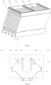
- Said sloping plate assembly includes a supporting plate 61, a multi-opening clamping plate 62, a sloping plate 63, a fastening plate 65 and a collector pipe 66. Both sides of the multi-opening clamping plate 62 are fixed on the supporting plate 61.
- the angle between the multi-opening clamping plate 62 and the perpendicular direction is 30°.
- the multi-opening clamping plates 62 are installed in parallel.
- More than one multi-opening clamping plate 62 may be arranged in parallel according to the strength of the sloping plate.
- Parallel sloping plate grooves are defined on the multi-opening clamping plate 62.
- the sloping plate 63 is fixed on the multi-opening clamping plate 62 by the sloping plate grooves.
- Fluid passages are formed between sloping plates 63.
- a collector pipe 66 is arranged at the end of said fluid passage.
- the top of the multi-opening clamping plate 62 is tightly held by the fastening plate 65 and fixed by bolt 64.
- the collector pipe 66 is a perforated pipe; each said collector pipe has the same number and aperture of holes, so as to achieve the purpose of uniform liquid gathering.
- Said collector pipes 66 are installed in the vicinity of each or every two fluid passage ends, so as to make the amount of liquid collected by each fluid passage the same, and also make the separate load reaching each sloping plate the same.
- the liquid collected by said collector pipes 66 may be gathered to and discharged from the collecting and discharging pipe 7.
- a scum or floating oil collection and concentration system comprises a scum or floating oil concentration device comprising a scum or floating oil concentration cone 11 and a scum or floating oil conveyor 12 fixed on said scum or floating oil concentration cone 11, and an emulsion scum or floating oil collection device comprising a emulsion device 14 and a floating weir skimmer 15.
- the scum or floating oil concentration cone 11 is of a trapezium where the upper side is narrow and the lower side is wide.
- Said scum or floating oil conveyor 12 includes a conveying helix 1 rotating around a shaft, a scum or floating oil conveying pipe 2 and a skimmer 3.
- Said conveying helix 1 is arranged inside said scum or floating oil conveying pipe 2.
- An opening 9 is arranged on said scum or floating oil conveying pipe 2.
- Said fan-shaped skimmer 3 is arranged at said opening 9 of said scum or floating oil conveying pipe 2.
- a scum or floating oil outlet 4 is arranged on said scum or floating oil conveyor 12.
- the conveying helix 1 rotates and pushes the scum or floating oil to and discharges the same from said scum or floating oil outlet 4.
- a separation device 6 is arranged under said scum or floating oil concentration cone 11.
- An inclined separation plate 13 is arranged inside said separation device 6.
- a fluid inlet 8, a discharge pipe 7 and a clear liquid outlet 5 are arranged on said separation device 6.
- a disinfecting device 10 may also be arranged between said scum or floating oil concentration cone 11 and said scum or floating oil conveyor 12.
- Said disinfecting device 10 can be any type of disinfection and sterilization equipment in this field, such as UV disinfecting device, ozone disinfecting device or sterilizing-solution disinfecting device; UV disinfecting device is preferred in this embodiment.
- Said emulsion device 14 may be an emulsion storage tank or a vacuum filter, etc.
- Said floating weir skimmer 15 is arranged inside said emulsion device 14. The skimmer may be fixed on said emulsion device 14, or float on the liquid surface of said emulsion device 14 with the help of a floater.
- Said floating weir skimmer 15 comprises a collecting box 150, a weir plate 151 and an inner buoy 152.
- Said collecting box 150 comprises two baffle plates 153 and one trough 154.
- Said trough 154 is provided with a guide rail 155.
- An inner buoy 152 is arranged inside said collecting box 150.
- a guide pulley 156 is arranged on both ends of said inner buoy 152 enabling said inner buoy 152 to slide on said guide rail 155.
- Said inner buoy 152 floats with the help by the liquid buoyancy in said collecting box 150.
- the level changes in said collecting box 150 enables said inner buoy 152 to float along said guide rail 155 relying on said guide pulley 156.
- a supporting member is also provided on said inner buoy 152.
- One end of said weir plate 151 is supported by a supporting member, and the other end is connected to said trough 154.
- Said supporting member includes an adjustable bolt and a carrying block. Said carrying block is fixed on said adjustable bolt.
- Said carrying block can reach a certain height by adjusting the bolt, so as to determine the initial weir crest height.
- said weir plate 151 is double-side weir plate; namely, both sides of said inner buoy 152 are provided with said weir plate 151.
- Said weir plate 151 is in rotation connection with said trough 154.
- Said rotation connection may also be other connection methods conventionally used in this field, as long as the rotation of said weir plate 151 can be achieved. Hinge connection is preferred in this embodiment.
- Said weir plate 151 presses on the carrying block relying on its own gravity and moves with said carrying block moving up and down. Weir crest and weir are arranged on said weir plate 151 with an interval.
- the weir crest height on both sides of the double-side weir plate may vary with the amounts of scum or floating oil on both sides.
- Said weir plate 151 may also be a single-side weir plate, with the other side being enclosed, collecting scum or floating oil on a single side.
- a liquid outlet 157 is also arranged under said collecting box 150. Said liquid outlet 157 is connected with the fluid inlet 8 of the scum or floating oil concentration device.
- Said emulsion scum or floating oil collection device which may be field storage tank or vacuum filter, may be one set or more than one set. This embodiment provides two sets of emulsion scum or floating oil collection device, which are connected with the scum or floating oil concentration device through a pipeline.
- a pump 16 may be installed on said pipeline.
- the operating principle of the scum or floating oil collection and concentration system is as follows: during the collection process of the emulsion scum or floating oil, the scum or floating oil inside the emulsion device 14 will be collected by the floating weir skimmer 15; open the liquid outlet 157, the liquid level in the collecting box 150 will decrease; the inner buoy 152 will float due to changes of liquid level in the collecting box 150; the inner buoy 152 moves downwards, driving the adjustable bolt and the carrying block to also move downwards, further driving the weir plate 151 to rotate; the scum or floating oil outside the trough 154 will enter the collecting box 150 through the crest of weir; after finishing collection, close the liquid outlet 157, the inner buoy 152 and the weir plate 151 will return to their original positions.
- the liquid level of the floating weir skimmer 15 in the emulsion device 14 is higher than the scum or floating oil concentration device, the liquid can flow automatically into the scum or floating oil concentration device; when the liquid level of the floating weir skimmer 15 in the emulsion device 14 is lower than the scum or floating oil concentration device, a pump 16 may be used for pumping the liquid into the scum or floating oil concentration device.
- the scum or floating oil entering through the fluid inlet 8 of the separation device 6 will be separated by the inclined separation plate 13, and the clear liquid after separation will be discharged from the clear liquid outlet 5 and then recycled.
- scum or floating oil is accumulated in the scum or floating oil concentration cone 11; when the scum or floating oil becomes concentrated, it may be deteriorated and moldy; at this time, the disinfecting device 10 needs to be engaged for disinfection and sterilization of the scum or floating oil, as well as for disinfection and sterilization of the liquid in the separation device 6; when the concentration of scum or floating oil reaches a certain level, the skimmer 3 needs to be engaged to scoop out the dense scum or floating oil and dump the same into the scum or floating oil conveying pipe 2, and at the same time, open the screw conveyer 1 to push the dense scum or floating oil dumped into the conveying pipe to the outlet 4 for discharge.
- the dense scum or floating oil has a low liquid content but a high scum or floating oil concentration, thus saving a large amount of raw liquid.
Landscapes
- Chemical & Material Sciences (AREA)
- Chemical Kinetics & Catalysis (AREA)
- Physics & Mathematics (AREA)
- Thermal Sciences (AREA)
- Removal Of Floating Material (AREA)
Claims (6)
- Eine Konzentrationsvorrichtung für Schaum oder schwimmendes Öl, die einen Konzentrationskegel (11) für Schaum oder schwimmendes Öl und ein Fördermittel (12) für Schaum oder schwimmendes Öl beinhaltet, wobei das Fördermittel (12) für Schaum oder schwimmendes Öl über dem Konzentrationskegel (11) für Schaum oder schwimmendes Öl eingerichtet ist; das Fördermittel (12) für Schaum oder schwimmendes Öl Folgendes beinhaltet: eine Förderschnecke (1), die sich um eine Welle dreht, ein Förderrohr (2) für Schaum oder schwimmendes Öl und einen Abschöpfer (3); die Förderschnecke (1) innerhalb des Förderrohrs (2) für Schaum oder schwimmendes Öl eingerichtet ist; eine Öffnung (9) auf dem Förderrohr (2) für Schaum oder schwimmendes Öl eingerichtet ist; der Abschöpfer (3) an der Öffnung (9) des Förderrohrs (2) für Schaum oder schwimmendes Öl eingerichtet ist; wobei der Konzentrationskegel (11) für Schaum oder schwimmendes Öl an der Oberseite schmal und an der Unterseite breit ist; wobei sich die Förderschnecke (1) gänzlich über dem Konzentrationskegel (11) für Schaum oder schwimmendes Öl befindet; und wobei eine Trennvorrichtung (6) unter dem Konzentrationskegel (11) für Schaum oder schwimmendes Öl eingerichtet ist und ein Fluideinlass (8) und ein Auslass (5) für klare Flüssigkeit an der Trennvorrichtung (6) eingerichtet sind; wobei eine geneigte Trennplatte (13) innerhalb der Trennvorrichtung (6) unter dem Konzentrationskegel (11) für Schaum oder schwimmendes Öl und über dem Fluideinlass (8) eingerichtet ist; und dadurch gekennzeichnet, dass der Abschöpfer an das Förderrohr (2) für Schaum oder schwimmendes Öl geschweißt ist, wobei der Abschöpfer (3) eingerichtet ist, um sich mit dem Förderrohr (2) für Schaum oder schwimmendes Öl zu drehen und geschöpften Schaum oder geschöpftes schwimmendes Öl durch die Öffnung (9) auf dem Förderrohr (2) für Schaum oder schwimmendes Öl in das Förderrohr (2) für Schaum oder schwimmendes Öl einzuleiten, und wobei der Abschöpfer (3) fächerförmig ist.
- Konzentrationsvorrichtung für Schaum oder schwimmendes Öl gemäß Anspruch 1, wobei zwischen dem Konzentrationskegel (11) für Schaum oder schwimmendes Öl und dem Fördermittel (12) für Schaum oder schwimmendes Öl eine Desinfektionsvorrichtung (10) eingerichtet ist.
- Konzentrationsvorrichtung für Schaum oder schwimmendes Öl gemäß Anspruch 2, wobei die Desinfektionsvorrichtung (10) eine UV-Desinfektionsvorrichtung, eine Ozondesinfektionsvorrichtung oder eine Desinfektionsvorrichtung mit Sterilisierungslösung ist.
- Konzentrationsvorrichtung für Schaum oder schwimmendes Öl gemäß Anspruch 1, wobei innerhalb der Trennvorrichtung (6) zwischen dem Fluideinlass (8) und dem Auslass (5) für klare Flüssigkeit eine Anordnung schräger Platten eingerichtet ist; die Anordnung schräger Platten eine Stützplatte (61), eine Klemmplatte (62) mit mehreren Öffnungen, eine schräge Platte (63), eine Befestigungsplatte (65) und ein Sammlerrohr (66) umfasst; beide Seiten der Klemmplatte (62) mit mehreren Öffnungen an der Stützplatte (61) fixiert sind; parallele Rillen für schräge Platten auf der Klemmplatte (62) mit mehreren Öffnungen definiert sind; die schräge Platte (63) durch die Rillen für schräge Platten an der Klemmplatte (62) mit mehreren Öffnungen fixiert ist; zwischen schrägen Platten (63) Fluiddurchgänge gebildet sind; ein Sammlerrohr (66) an dem Ende des Fluiddurchgangs eingerichtet ist; ein Loch auf der Oberfläche des Sammlerrohrs (66) für den Durchgang von Fluid eingerichtet ist; die Klemmplatten (62) mit mehreren Öffnungen parallel installiert sind; das obere Ende der Klemmplatte (62) mit mehreren Öffnungen durch die Befestigungsplatte (65) fixiert ist.
- Ein Sammel- und Konzentrationssystem für Schaum oder schwimmendes Öl, das eine Konzentrationsvorrichtung für Schaum oder schwimmendes Öl gemäß Anspruch 1 aufweist und ferner Folgendes beinhaltet:
eine Sammelvorrichtung für Emulsionsschaum oder schwimmendes Öl, die eine Emulsionsvorrichtung (14) und einen schwimmenden Überlaufplatten-Abschöpfer (15) beinhaltet, wobei der schwimmende Überlaufplatten-Abschöpfer (15) innerhalb der Emulsionsvorrichtung (14) eingerichtet ist; der schwimmende Überlaufplatten-Abschöpfer (15) einen Sammelkasten (150), eine Überlaufplatte (151) und einen inneren Schwimmkörper (152) umfasst; der Sammelkasten (150) eine Ablenkplatte (153) und eine Wanne (154) umfasst; die Wanne (154) mit einer Führungsschiene (155) versehen ist; ein innerer Schwimmkörper (152) innerhalb des Sammelkastens (150) eingerichtet ist; eine Führungsrolle (156) an dem inneren Schwimmkörper (152) eingerichtet ist, die ermöglicht, dass der innere Schwimmkörper (152) an der Führungsschiene (155) gleitet; ein Stützelement ebenfalls an dem inneren Schwimmkörper (152) eingerichtet ist; ein Ende der Überlaufplatte (151) durch das Stützelement gestützt wird und das andere Ende in Drehverbindung mit der Wanne (154) steht; ein Flüssigkeitsauslass (157) unter dem Sammelkasten (150) eingerichtet ist; und der Flüssigkeitsauslass (157) durch eine Rohrleitung mit dem Fluideinlass (8) der Konzentrationsvorrichtung für Schaum oder schwimmendes Öl verbunden ist. - Sammel- und Konzentrationssystem für Schaum oder schwimmendes Öl gemäß Anspruch 5, wobei die Anzahl der Sammelvorrichtungen für Emulsionsschaum oder schwimmendes Öl mindestens ein Satz ist, die Sammelvorrichtung für Emulsionsschaum oder schwimmendes Öl durch eine Rohrleitung mit der Konzentrationsvorrichtung für Schaum oder schwimmendes Öl verbunden ist und eine Pumpe (16) an der Rohrleitung eingerichtet ist.
Applications Claiming Priority (1)
| Application Number | Priority Date | Filing Date | Title |
|---|---|---|---|
| PCT/CN2016/074534 WO2017143554A1 (zh) | 2016-02-25 | 2016-02-25 | 浮渣浓缩装置 |
Publications (3)
| Publication Number | Publication Date |
|---|---|
| EP3308844A1 EP3308844A1 (de) | 2018-04-18 |
| EP3308844A4 EP3308844A4 (de) | 2018-07-04 |
| EP3308844B1 true EP3308844B1 (de) | 2023-07-05 |
Family
ID=59684829
Family Applications (1)
| Application Number | Title | Priority Date | Filing Date |
|---|---|---|---|
| EP16891008.1A Active EP3308844B1 (de) | 2016-02-25 | 2016-02-25 | Schlackenkonzentrationsvorrichtung |
Country Status (3)
| Country | Link |
|---|---|
| US (1) | US10413848B2 (de) |
| EP (1) | EP3308844B1 (de) |
| WO (1) | WO2017143554A1 (de) |
Families Citing this family (8)
| Publication number | Priority date | Publication date | Assignee | Title |
|---|---|---|---|---|
| EP3308843B1 (de) * | 2016-02-25 | 2019-09-11 | Dalian Yooqi Water Treatment Technology Co., Ltd. | Schwimmender überlauf zur abschöpfung |
| CN107758853B (zh) * | 2017-11-24 | 2020-10-27 | 山东高速环保科技有限公司 | 一种污水处理用曝气池 |
| CN108483569B (zh) * | 2018-05-30 | 2021-06-08 | 广东知识城运营服务有限公司 | 一种污水处理池浮泥渣集边去除装置 |
| CN109179548A (zh) * | 2018-11-12 | 2019-01-11 | 新乡市绿丰环保工程有限公司 | 涡凹气浮机及其运行方法 |
| US12611621B2 (en) | 2019-03-27 | 2026-04-28 | Battelle Memorial Institute | Separator assemblies and methods |
| US12544799B2 (en) | 2019-03-27 | 2026-02-10 | Battelle Memorial Institute | Separator assemblies and methods |
| CN111252850B (zh) * | 2020-03-17 | 2024-08-23 | 大连起泰环保科技有限公司 | 一种前置分离装置 |
| CN113457223B (zh) * | 2021-08-06 | 2022-11-25 | 安徽华安食品有限公司 | 一种芝麻油生产用震荡分油装置及其实施方法 |
Citations (1)
| Publication number | Priority date | Publication date | Assignee | Title |
|---|---|---|---|---|
| EP1193342A1 (de) * | 2000-09-27 | 2002-04-03 | Meri Entsorgungstechnik für die Papierindustrie GmbH | Säulen-Flotationsvorrichtung |
Family Cites Families (23)
| Publication number | Priority date | Publication date | Assignee | Title |
|---|---|---|---|---|
| DE658300C (de) * | 1934-03-11 | 1938-03-26 | I G Farbenindustrie Akt Ges | Vorrichtung zur Trennung miteinander vermischter Fluessigkeiten von verschiedenem spezifischem Gewicht |
| US2955714A (en) * | 1956-11-19 | 1960-10-11 | Phillips Petroleum Co | Apparatus for separating solids and liquids |
| US3447683A (en) * | 1967-05-15 | 1969-06-03 | Laval Turbine | Separation apparatus and method for mixed impurities on the exposed surface of a liquid body |
| DE3600952A1 (de) * | 1986-01-15 | 1987-07-16 | Piepho Abwassertech Ralf F | Vorrichtung zur entfernung von schwimmschlamm auf fluessigkeitsoberflaechen |
| US5188729A (en) * | 1988-09-07 | 1993-02-23 | Lenox Institute For Research, Inc. | Sludge collection apparatus for a water clarifier |
| US5028333A (en) * | 1990-02-23 | 1991-07-02 | Mercer International, Inc. | Phase separator module |
| SE468158B (sv) * | 1990-07-19 | 1992-11-16 | Spirac Engineering Ab | Saett och anordning foer avskiljning och avlaegsnande av kroppar ur en vaetska |
| US5538631A (en) * | 1995-03-08 | 1996-07-23 | Yeh; George C. | Method and apparatus for dissolved air flotation and related waste water treatments |
| FR2775968B1 (fr) * | 1998-03-16 | 2000-07-13 | Degremont | Dispositif assurant la recuperation des flottants dans des bassins de decantation |
| US6277273B1 (en) * | 1999-06-22 | 2001-08-21 | U.S. Hydrex, Inc. | Floating decanter for supernatant liquid |
| US6267877B1 (en) * | 2000-02-25 | 2001-07-31 | Anthony J. Bianco | Separation of a waste phase from a water based emulsion |
| FI116715B (fi) * | 2004-06-29 | 2006-02-15 | Finnketju Invest Oy | Menetelmä ja järjestely pintalietteen poistoon |
| KR100712962B1 (ko) * | 2007-01-26 | 2007-05-02 | 뮤러아시아(주) | 경사판 침전설비 |
| US8277652B2 (en) * | 2007-02-13 | 2012-10-02 | Urquhart Gordon T | Oil-sludge filtration system with aeration pump |
| FI119758B (fi) * | 2007-08-13 | 2009-03-13 | Finnketju Invest Oy | Menetelmä ja poistojärjestely pintalietteen poistossa |
| US7850860B2 (en) * | 2009-03-25 | 2010-12-14 | Jim Myers & Sons, Inc. | Plate settler with angular support members |
| US8585896B2 (en) * | 2011-06-10 | 2013-11-19 | Roberts Marketing De, Inc. | Apparatus and method for removing impurities from water of wastewater |
| CN105174366A (zh) * | 2015-08-14 | 2015-12-23 | 昌邑海洋水业有限公司 | 浮渣清理装置 |
| CN205007709U (zh) * | 2015-08-31 | 2016-02-03 | 江苏天雨环保集团有限公司 | 新型内进式旋转滤网格栅除污机 |
| CN105521625A (zh) * | 2016-02-25 | 2016-04-27 | 大连涌清水处理技术有限公司 | 一种均匀集液斜板组件 |
| CN205391805U (zh) * | 2016-02-25 | 2016-07-27 | 大连涌清水处理技术有限公司 | 一种均匀集液斜板组件 |
| EP3308843B1 (de) * | 2016-02-25 | 2019-09-11 | Dalian Yooqi Water Treatment Technology Co., Ltd. | Schwimmender überlauf zur abschöpfung |
| CN205516682U (zh) * | 2016-02-25 | 2016-08-31 | 大连涌清水处理技术有限公司 | 浮渣浓缩装置 |
-
2016
- 2016-02-25 EP EP16891008.1A patent/EP3308844B1/de active Active
- 2016-02-25 WO PCT/CN2016/074534 patent/WO2017143554A1/zh not_active Ceased
-
2017
- 2017-12-17 US US15/844,545 patent/US10413848B2/en active Active
Patent Citations (1)
| Publication number | Priority date | Publication date | Assignee | Title |
|---|---|---|---|---|
| EP1193342A1 (de) * | 2000-09-27 | 2002-04-03 | Meri Entsorgungstechnik für die Papierindustrie GmbH | Säulen-Flotationsvorrichtung |
Also Published As
| Publication number | Publication date |
|---|---|
| EP3308844A1 (de) | 2018-04-18 |
| EP3308844A4 (de) | 2018-07-04 |
| WO2017143554A1 (zh) | 2017-08-31 |
| US10413848B2 (en) | 2019-09-17 |
| US20180104621A1 (en) | 2018-04-19 |
Similar Documents
| Publication | Publication Date | Title |
|---|---|---|
| US10413848B2 (en) | Scum concentration device | |
| DE112011100234B4 (de) | Selbstreinigendes Zulaufeinspeisungssystem für ein Abwasseraufbereitungssystem | |
| CN102674580B (zh) | 自动刮渣收油式渣油泥水四相分离设备 | |
| CN103570151A (zh) | 自动型餐饮污水处理设备及其处理方法 | |
| JP2010131503A (ja) | 油水分離回収装置 | |
| CN207031098U (zh) | 一种废水隔油槽 | |
| CN107619122B (zh) | 带集油回流装置的餐饮污水处理设备及其工作方法 | |
| CN202555013U (zh) | 一种旋液浮油收集排油装置 | |
| CN102397712B (zh) | 带浮油吸收器的移动式油水分离装置 | |
| CN203568912U (zh) | 自动型餐饮污水处理设备 | |
| RU2372295C1 (ru) | Установка для очистки нефтесодержащих жидкостей | |
| US8182700B2 (en) | Method and exhaust arrangement in the removal of surface scum | |
| CN201596381U (zh) | 一种除油装置 | |
| CN105457346B (zh) | 一种带沉淀墙的沉淀池装置 | |
| CN205340235U (zh) | 一种带沉淀墙的沉淀池装置 | |
| CN205516682U (zh) | 浮渣浓缩装置 | |
| CN110655147A (zh) | 餐厨油水分离装置及餐厨垃圾处理系统 | |
| KR200343484Y1 (ko) | 수처리장치의 협잡물 분리 제거장치 | |
| CN214653795U (zh) | 一种免维护隔油池 | |
| CN116589031A (zh) | 一种油水分离装置及方法 | |
| RU2465944C2 (ru) | Устройство разделения фаз в водонефтяной смеси - наклонный отстойник | |
| KR100543079B1 (ko) | 분뇨, 하수, 축산 폐수 등의 전처리 방법 | |
| RU2827609C1 (ru) | Пластинчатый сгуститель | |
| RU2628376C1 (ru) | Комплекс для очистки промышленных сбросов и сточных вод | |
| CN221836790U (zh) | 无动力自调节的油水分离设备 |
Legal Events
| Date | Code | Title | Description |
|---|---|---|---|
| STAA | Information on the status of an ep patent application or granted ep patent |
Free format text: STATUS: THE INTERNATIONAL PUBLICATION HAS BEEN MADE |
|
| PUAI | Public reference made under article 153(3) epc to a published international application that has entered the european phase |
Free format text: ORIGINAL CODE: 0009012 |
|
| STAA | Information on the status of an ep patent application or granted ep patent |
Free format text: STATUS: REQUEST FOR EXAMINATION WAS MADE |
|
| 17P | Request for examination filed |
Effective date: 20180115 |
|
| AK | Designated contracting states |
Kind code of ref document: A1 Designated state(s): AL AT BE BG CH CY CZ DE DK EE ES FI FR GB GR HR HU IE IS IT LI LT LU LV MC MK MT NL NO PL PT RO RS SE SI SK SM TR |
|
| AX | Request for extension of the european patent |
Extension state: BA ME |
|
| A4 | Supplementary search report drawn up and despatched |
Effective date: 20180605 |
|
| RIC1 | Information provided on ipc code assigned before grant |
Ipc: B01D 21/24 20060101AFI20180529BHEP Ipc: B01D 17/02 20060101ALI20180529BHEP Ipc: B01D 21/02 20060101ALI20180529BHEP Ipc: B01D 21/00 20060101ALI20180529BHEP |
|
| DAV | Request for validation of the european patent (deleted) | ||
| DAX | Request for extension of the european patent (deleted) | ||
| STAA | Information on the status of an ep patent application or granted ep patent |
Free format text: STATUS: EXAMINATION IS IN PROGRESS |
|
| 17Q | First examination report despatched |
Effective date: 20210219 |
|
| REG | Reference to a national code |
Ref country code: DE Ref legal event code: R079 Free format text: PREVIOUS MAIN CLASS: B01D0021240000 Ipc: B01D0017040000 Ref document number: 602016080887 Country of ref document: DE |
|
| RIC1 | Information provided on ipc code assigned before grant |
Ipc: B01D 21/24 20060101ALI20230130BHEP Ipc: B01D 17/02 20060101ALI20230130BHEP Ipc: B01D 21/02 20060101ALI20230130BHEP Ipc: B01D 21/00 20060101ALI20230130BHEP Ipc: B01D 17/04 20060101AFI20230130BHEP |
|
| GRAP | Despatch of communication of intention to grant a patent |
Free format text: ORIGINAL CODE: EPIDOSNIGR1 |
|
| STAA | Information on the status of an ep patent application or granted ep patent |
Free format text: STATUS: GRANT OF PATENT IS INTENDED |
|
| INTG | Intention to grant announced |
Effective date: 20230331 |
|
| GRAS | Grant fee paid |
Free format text: ORIGINAL CODE: EPIDOSNIGR3 |
|
| GRAA | (expected) grant |
Free format text: ORIGINAL CODE: 0009210 |
|
| STAA | Information on the status of an ep patent application or granted ep patent |
Free format text: STATUS: THE PATENT HAS BEEN GRANTED |
|
| AK | Designated contracting states |
Kind code of ref document: B1 Designated state(s): AL AT BE BG CH CY CZ DE DK EE ES FI FR GB GR HR HU IE IS IT LI LT LU LV MC MK MT NL NO PL PT RO RS SE SI SK SM TR |
|
| REG | Reference to a national code |
Ref country code: CH Ref legal event code: EP |
|
| REG | Reference to a national code |
Ref country code: AT Ref legal event code: REF Ref document number: 1584297 Country of ref document: AT Kind code of ref document: T Effective date: 20230715 |
|
| REG | Reference to a national code |
Ref country code: DE Ref legal event code: R096 Ref document number: 602016080887 Country of ref document: DE |
|
| REG | Reference to a national code |
Ref country code: IE Ref legal event code: FG4D |
|
| P01 | Opt-out of the competence of the unified patent court (upc) registered |
Effective date: 20230711 |
|
| REG | Reference to a national code |
Ref country code: LT Ref legal event code: MG9D |
|
| REG | Reference to a national code |
Ref country code: NL Ref legal event code: MP Effective date: 20230705 |
|
| PG25 | Lapsed in a contracting state [announced via postgrant information from national office to epo] |
Ref country code: NL Free format text: LAPSE BECAUSE OF FAILURE TO SUBMIT A TRANSLATION OF THE DESCRIPTION OR TO PAY THE FEE WITHIN THE PRESCRIBED TIME-LIMIT Effective date: 20230705 |
|
| PG25 | Lapsed in a contracting state [announced via postgrant information from national office to epo] |
Ref country code: GR Free format text: LAPSE BECAUSE OF FAILURE TO SUBMIT A TRANSLATION OF THE DESCRIPTION OR TO PAY THE FEE WITHIN THE PRESCRIBED TIME-LIMIT Effective date: 20231006 |
|
| PG25 | Lapsed in a contracting state [announced via postgrant information from national office to epo] |
Ref country code: ES Free format text: LAPSE BECAUSE OF FAILURE TO SUBMIT A TRANSLATION OF THE DESCRIPTION OR TO PAY THE FEE WITHIN THE PRESCRIBED TIME-LIMIT Effective date: 20230705 |
|
| PG25 | Lapsed in a contracting state [announced via postgrant information from national office to epo] |
Ref country code: IS Free format text: LAPSE BECAUSE OF FAILURE TO SUBMIT A TRANSLATION OF THE DESCRIPTION OR TO PAY THE FEE WITHIN THE PRESCRIBED TIME-LIMIT Effective date: 20231105 |
|
| PG25 | Lapsed in a contracting state [announced via postgrant information from national office to epo] |
Ref country code: SE Free format text: LAPSE BECAUSE OF FAILURE TO SUBMIT A TRANSLATION OF THE DESCRIPTION OR TO PAY THE FEE WITHIN THE PRESCRIBED TIME-LIMIT Effective date: 20230705 Ref country code: RS Free format text: LAPSE BECAUSE OF FAILURE TO SUBMIT A TRANSLATION OF THE DESCRIPTION OR TO PAY THE FEE WITHIN THE PRESCRIBED TIME-LIMIT Effective date: 20230705 Ref country code: PT Free format text: LAPSE BECAUSE OF FAILURE TO SUBMIT A TRANSLATION OF THE DESCRIPTION OR TO PAY THE FEE WITHIN THE PRESCRIBED TIME-LIMIT Effective date: 20231106 Ref country code: NO Free format text: LAPSE BECAUSE OF FAILURE TO SUBMIT A TRANSLATION OF THE DESCRIPTION OR TO PAY THE FEE WITHIN THE PRESCRIBED TIME-LIMIT Effective date: 20231005 Ref country code: LV Free format text: LAPSE BECAUSE OF FAILURE TO SUBMIT A TRANSLATION OF THE DESCRIPTION OR TO PAY THE FEE WITHIN THE PRESCRIBED TIME-LIMIT Effective date: 20230705 Ref country code: LT Free format text: LAPSE BECAUSE OF FAILURE TO SUBMIT A TRANSLATION OF THE DESCRIPTION OR TO PAY THE FEE WITHIN THE PRESCRIBED TIME-LIMIT Effective date: 20230705 Ref country code: IS Free format text: LAPSE BECAUSE OF FAILURE TO SUBMIT A TRANSLATION OF THE DESCRIPTION OR TO PAY THE FEE WITHIN THE PRESCRIBED TIME-LIMIT Effective date: 20231105 Ref country code: HR Free format text: LAPSE BECAUSE OF FAILURE TO SUBMIT A TRANSLATION OF THE DESCRIPTION OR TO PAY THE FEE WITHIN THE PRESCRIBED TIME-LIMIT Effective date: 20230705 Ref country code: GR Free format text: LAPSE BECAUSE OF FAILURE TO SUBMIT A TRANSLATION OF THE DESCRIPTION OR TO PAY THE FEE WITHIN THE PRESCRIBED TIME-LIMIT Effective date: 20231006 Ref country code: FI Free format text: LAPSE BECAUSE OF FAILURE TO SUBMIT A TRANSLATION OF THE DESCRIPTION OR TO PAY THE FEE WITHIN THE PRESCRIBED TIME-LIMIT Effective date: 20230705 Ref country code: ES Free format text: LAPSE BECAUSE OF FAILURE TO SUBMIT A TRANSLATION OF THE DESCRIPTION OR TO PAY THE FEE WITHIN THE PRESCRIBED TIME-LIMIT Effective date: 20230705 |
|
| REG | Reference to a national code |
Ref country code: AT Ref legal event code: UEP Ref document number: 1584297 Country of ref document: AT Kind code of ref document: T Effective date: 20230705 |
|
| PG25 | Lapsed in a contracting state [announced via postgrant information from national office to epo] |
Ref country code: PL Free format text: LAPSE BECAUSE OF FAILURE TO SUBMIT A TRANSLATION OF THE DESCRIPTION OR TO PAY THE FEE WITHIN THE PRESCRIBED TIME-LIMIT Effective date: 20230705 |
|
| REG | Reference to a national code |
Ref country code: DE Ref legal event code: R097 Ref document number: 602016080887 Country of ref document: DE |
|
| PG25 | Lapsed in a contracting state [announced via postgrant information from national office to epo] |
Ref country code: SM Free format text: LAPSE BECAUSE OF FAILURE TO SUBMIT A TRANSLATION OF THE DESCRIPTION OR TO PAY THE FEE WITHIN THE PRESCRIBED TIME-LIMIT Effective date: 20230705 Ref country code: RO Free format text: LAPSE BECAUSE OF FAILURE TO SUBMIT A TRANSLATION OF THE DESCRIPTION OR TO PAY THE FEE WITHIN THE PRESCRIBED TIME-LIMIT Effective date: 20230705 Ref country code: EE Free format text: LAPSE BECAUSE OF FAILURE TO SUBMIT A TRANSLATION OF THE DESCRIPTION OR TO PAY THE FEE WITHIN THE PRESCRIBED TIME-LIMIT Effective date: 20230705 Ref country code: DK Free format text: LAPSE BECAUSE OF FAILURE TO SUBMIT A TRANSLATION OF THE DESCRIPTION OR TO PAY THE FEE WITHIN THE PRESCRIBED TIME-LIMIT Effective date: 20230705 Ref country code: CZ Free format text: LAPSE BECAUSE OF FAILURE TO SUBMIT A TRANSLATION OF THE DESCRIPTION OR TO PAY THE FEE WITHIN THE PRESCRIBED TIME-LIMIT Effective date: 20230705 Ref country code: SK Free format text: LAPSE BECAUSE OF FAILURE TO SUBMIT A TRANSLATION OF THE DESCRIPTION OR TO PAY THE FEE WITHIN THE PRESCRIBED TIME-LIMIT Effective date: 20230705 |
|
| PLBE | No opposition filed within time limit |
Free format text: ORIGINAL CODE: 0009261 |
|
| STAA | Information on the status of an ep patent application or granted ep patent |
Free format text: STATUS: NO OPPOSITION FILED WITHIN TIME LIMIT |
|
| PG25 | Lapsed in a contracting state [announced via postgrant information from national office to epo] |
Ref country code: IT Free format text: LAPSE BECAUSE OF FAILURE TO SUBMIT A TRANSLATION OF THE DESCRIPTION OR TO PAY THE FEE WITHIN THE PRESCRIBED TIME-LIMIT Effective date: 20230705 |
|
| 26N | No opposition filed |
Effective date: 20240408 |
|
| PG25 | Lapsed in a contracting state [announced via postgrant information from national office to epo] |
Ref country code: SI Free format text: LAPSE BECAUSE OF FAILURE TO SUBMIT A TRANSLATION OF THE DESCRIPTION OR TO PAY THE FEE WITHIN THE PRESCRIBED TIME-LIMIT Effective date: 20230705 |
|
| PG25 | Lapsed in a contracting state [announced via postgrant information from national office to epo] |
Ref country code: MC Free format text: LAPSE BECAUSE OF FAILURE TO SUBMIT A TRANSLATION OF THE DESCRIPTION OR TO PAY THE FEE WITHIN THE PRESCRIBED TIME-LIMIT Effective date: 20230705 |
|
| PG25 | Lapsed in a contracting state [announced via postgrant information from national office to epo] |
Ref country code: LU Free format text: LAPSE BECAUSE OF NON-PAYMENT OF DUE FEES Effective date: 20240225 |
|
| PG25 | Lapsed in a contracting state [announced via postgrant information from national office to epo] |
Ref country code: LU Free format text: LAPSE BECAUSE OF NON-PAYMENT OF DUE FEES Effective date: 20240225 |
|
| PG25 | Lapsed in a contracting state [announced via postgrant information from national office to epo] |
Ref country code: BG Free format text: LAPSE BECAUSE OF FAILURE TO SUBMIT A TRANSLATION OF THE DESCRIPTION OR TO PAY THE FEE WITHIN THE PRESCRIBED TIME-LIMIT Effective date: 20230705 |
|
| PG25 | Lapsed in a contracting state [announced via postgrant information from national office to epo] |
Ref country code: BG Free format text: LAPSE BECAUSE OF FAILURE TO SUBMIT A TRANSLATION OF THE DESCRIPTION OR TO PAY THE FEE WITHIN THE PRESCRIBED TIME-LIMIT Effective date: 20230705 |
|
| REG | Reference to a national code |
Ref country code: BE Ref legal event code: MM Effective date: 20240229 |
|
| PG25 | Lapsed in a contracting state [announced via postgrant information from national office to epo] |
Ref country code: BE Free format text: LAPSE BECAUSE OF NON-PAYMENT OF DUE FEES Effective date: 20240229 |
|
| PG25 | Lapsed in a contracting state [announced via postgrant information from national office to epo] |
Ref country code: FR Free format text: LAPSE BECAUSE OF NON-PAYMENT OF DUE FEES Effective date: 20240229 |
|
| PG25 | Lapsed in a contracting state [announced via postgrant information from national office to epo] |
Ref country code: IE Free format text: LAPSE BECAUSE OF NON-PAYMENT OF DUE FEES Effective date: 20240225 |
|
| PG25 | Lapsed in a contracting state [announced via postgrant information from national office to epo] |
Ref country code: IE Free format text: LAPSE BECAUSE OF NON-PAYMENT OF DUE FEES Effective date: 20240225 Ref country code: FR Free format text: LAPSE BECAUSE OF NON-PAYMENT OF DUE FEES Effective date: 20240229 Ref country code: BE Free format text: LAPSE BECAUSE OF NON-PAYMENT OF DUE FEES Effective date: 20240229 |
|
| PG25 | Lapsed in a contracting state [announced via postgrant information from national office to epo] |
Ref country code: CY Free format text: LAPSE BECAUSE OF FAILURE TO SUBMIT A TRANSLATION OF THE DESCRIPTION OR TO PAY THE FEE WITHIN THE PRESCRIBED TIME-LIMIT; INVALID AB INITIO Effective date: 20160225 |
|
| PG25 | Lapsed in a contracting state [announced via postgrant information from national office to epo] |
Ref country code: HU Free format text: LAPSE BECAUSE OF FAILURE TO SUBMIT A TRANSLATION OF THE DESCRIPTION OR TO PAY THE FEE WITHIN THE PRESCRIBED TIME-LIMIT; INVALID AB INITIO Effective date: 20160225 |
|
| PG25 | Lapsed in a contracting state [announced via postgrant information from national office to epo] |
Ref country code: TR Free format text: LAPSE BECAUSE OF FAILURE TO SUBMIT A TRANSLATION OF THE DESCRIPTION OR TO PAY THE FEE WITHIN THE PRESCRIBED TIME-LIMIT Effective date: 20230705 |
|
| REG | Reference to a national code |
Ref country code: CH Ref legal event code: U11 Free format text: ST27 STATUS EVENT CODE: U-0-0-U10-U11 (AS PROVIDED BY THE NATIONAL OFFICE) Effective date: 20260301 |
|
| PGFP | Annual fee paid to national office [announced via postgrant information from national office to epo] |
Ref country code: GB Payment date: 20260226 Year of fee payment: 11 |
|
| PGFP | Annual fee paid to national office [announced via postgrant information from national office to epo] |
Ref country code: DE Payment date: 20260226 Year of fee payment: 11 |
|
| PGFP | Annual fee paid to national office [announced via postgrant information from national office to epo] |
Ref country code: AT Payment date: 20260227 Year of fee payment: 11 |
|
| PGFP | Annual fee paid to national office [announced via postgrant information from national office to epo] |
Ref country code: CH Payment date: 20260301 Year of fee payment: 11 |