EP3308865B1 - Générateur d'aérosol - Google Patents
Générateur d'aérosol Download PDFInfo
- Publication number
- EP3308865B1 EP3308865B1 EP17197100.5A EP17197100A EP3308865B1 EP 3308865 B1 EP3308865 B1 EP 3308865B1 EP 17197100 A EP17197100 A EP 17197100A EP 3308865 B1 EP3308865 B1 EP 3308865B1
- Authority
- EP
- European Patent Office
- Prior art keywords
- support member
- generating element
- vibration generating
- aerosol generator
- film
- Prior art date
- Legal status (The legal status is an assumption and is not a legal conclusion. Google has not performed a legal analysis and makes no representation as to the accuracy of the status listed.)
- Active
Links
Images



Classifications
-
- B—PERFORMING OPERATIONS; TRANSPORTING
- B05—SPRAYING OR ATOMISING IN GENERAL; APPLYING FLUENT MATERIALS TO SURFACES, IN GENERAL
- B05B—SPRAYING APPARATUS; ATOMISING APPARATUS; NOZZLES
- B05B17/00—Apparatus for spraying or atomising liquids or other fluent materials, not covered by the preceding groups
- B05B17/04—Apparatus for spraying or atomising liquids or other fluent materials, not covered by the preceding groups operating with special methods
- B05B17/06—Apparatus for spraying or atomising liquids or other fluent materials, not covered by the preceding groups operating with special methods using ultrasonic or other kinds of vibrations
- B05B17/0607—Apparatus for spraying or atomising liquids or other fluent materials, not covered by the preceding groups operating with special methods using ultrasonic or other kinds of vibrations generated by electrical means, e.g. piezoelectric transducers
- B05B17/0638—Apparatus for spraying or atomising liquids or other fluent materials, not covered by the preceding groups operating with special methods using ultrasonic or other kinds of vibrations generated by electrical means, e.g. piezoelectric transducers spray being produced by discharging the liquid or other fluent material through a plate comprising a plurality of orifices
- B05B17/0646—Vibrating plates, i.e. plates being directly subjected to the vibrations, e.g. having a piezoelectric transducer attached thereto
-
- A—HUMAN NECESSITIES
- A61—MEDICAL OR VETERINARY SCIENCE; HYGIENE
- A61M—DEVICES FOR INTRODUCING MEDIA INTO, OR ONTO, THE BODY; DEVICES FOR TRANSDUCING BODY MEDIA OR FOR TAKING MEDIA FROM THE BODY; DEVICES FOR PRODUCING OR ENDING SLEEP OR STUPOR
- A61M11/00—Sprayers or atomisers specially adapted for therapeutic purposes
- A61M11/001—Particle size control
-
- A—HUMAN NECESSITIES
- A61—MEDICAL OR VETERINARY SCIENCE; HYGIENE
- A61M—DEVICES FOR INTRODUCING MEDIA INTO, OR ONTO, THE BODY; DEVICES FOR TRANSDUCING BODY MEDIA OR FOR TAKING MEDIA FROM THE BODY; DEVICES FOR PRODUCING OR ENDING SLEEP OR STUPOR
- A61M11/00—Sprayers or atomisers specially adapted for therapeutic purposes
- A61M11/005—Sprayers or atomisers specially adapted for therapeutic purposes using ultrasonics
-
- A—HUMAN NECESSITIES
- A61—MEDICAL OR VETERINARY SCIENCE; HYGIENE
- A61M—DEVICES FOR INTRODUCING MEDIA INTO, OR ONTO, THE BODY; DEVICES FOR TRANSDUCING BODY MEDIA OR FOR TAKING MEDIA FROM THE BODY; DEVICES FOR PRODUCING OR ENDING SLEEP OR STUPOR
- A61M15/00—Inhalators
- A61M15/0085—Inhalators using ultrasonics
-
- B—PERFORMING OPERATIONS; TRANSPORTING
- B05—SPRAYING OR ATOMISING IN GENERAL; APPLYING FLUENT MATERIALS TO SURFACES, IN GENERAL
- B05B—SPRAYING APPARATUS; ATOMISING APPARATUS; NOZZLES
- B05B17/00—Apparatus for spraying or atomising liquids or other fluent materials, not covered by the preceding groups
- B05B17/04—Apparatus for spraying or atomising liquids or other fluent materials, not covered by the preceding groups operating with special methods
- B05B17/06—Apparatus for spraying or atomising liquids or other fluent materials, not covered by the preceding groups operating with special methods using ultrasonic or other kinds of vibrations
- B05B17/0607—Apparatus for spraying or atomising liquids or other fluent materials, not covered by the preceding groups operating with special methods using ultrasonic or other kinds of vibrations generated by electrical means, e.g. piezoelectric transducers
- B05B17/0623—Apparatus for spraying or atomising liquids or other fluent materials, not covered by the preceding groups operating with special methods using ultrasonic or other kinds of vibrations generated by electrical means, e.g. piezoelectric transducers coupled with a vibrating horn
- B05B17/063—Apparatus for spraying or atomising liquids or other fluent materials, not covered by the preceding groups operating with special methods using ultrasonic or other kinds of vibrations generated by electrical means, e.g. piezoelectric transducers coupled with a vibrating horn having an internal channel for supplying the liquid or other fluent material
-
- B—PERFORMING OPERATIONS; TRANSPORTING
- B05—SPRAYING OR ATOMISING IN GENERAL; APPLYING FLUENT MATERIALS TO SURFACES, IN GENERAL
- B05B—SPRAYING APPARATUS; ATOMISING APPARATUS; NOZZLES
- B05B17/00—Apparatus for spraying or atomising liquids or other fluent materials, not covered by the preceding groups
- B05B17/04—Apparatus for spraying or atomising liquids or other fluent materials, not covered by the preceding groups operating with special methods
- B05B17/06—Apparatus for spraying or atomising liquids or other fluent materials, not covered by the preceding groups operating with special methods using ultrasonic or other kinds of vibrations
- B05B17/0607—Apparatus for spraying or atomising liquids or other fluent materials, not covered by the preceding groups operating with special methods using ultrasonic or other kinds of vibrations generated by electrical means, e.g. piezoelectric transducers
- B05B17/0653—Details
Definitions
- This invention relates to aerosol generators.
- Aerosol generators of the type comprising a vibratable apertured membrane, a vibration generator such as a piezo element, and a support are known.
- An aerosol generator of this type is illustrated in Figs. 1 and 2 .
- a membrane 201 is supported by a metal washer 203 on top of which there is an annular piezo 202.
- the piezo 202 When the piezo 202 is electrically excited it moves in a radial direction as shown by the arrow A. This causes the apertured plate or membrane to move in a vertical direction as shown by the arrow B. This, in turn, causes liquid on the apertured plate to pass through the holes in the membrane 1 and thus delivering a fine mist of aerosol to the underside of the membrane 1.
- US5,435,282 also describes a nebulizer.
- the membrane is supported by a housing having a downwardly-depending skirt.
- the piezo is a discrete element on one side of the housing.
- a contact pin contacts the top surface of the piezo and another two pins contact the underside of the housing.
- the invention is directed towards providing an improved aerosol generator, in which soldered contacts are minimized or eliminated while also achieving a simple arrangement of parts.
- WO01/76762 describes a method of maximizing the mechanical displacement of a piezoelectric nebulizer apparatus.
- an aerosol generator as set out in claim 1.
- the film is cured adhesive.
- the adhesive comprises an epoxy
- the film has a hardness in the range of 70 to 85 Shore D.
- the film has a tensile modulus in the range of 2,000 - 7,000 MPa.
- the vibration generating element is secured to the support member by an adhesive, and the film is of the same material as said adhesive.
- the second conducting pin contacts an extension tab of the support member and said film is in the form of a discrete pad on the extension tab.
- said adhesive is spaced apart from adhesive under the vibration generating element.
- the generator further comprises a retainer supporting an assembly of the support member, the vibration generation element, and the vibratable member; wherein the retainer engages an underside of the support member via an annular seal and engages a top surface of the support member via a top counter-balancing annular seal.
- the top annular seal is adjacent the edge of the vibratable member and has a smaller radial dimension then the bottom annular seal.
- the bottom annular seal contacts the support member at a location underneath the vibration generating element, and the top annular seal contacts the support member laterally inside of the vibration generating element.
- an aerosol generator comprising:-
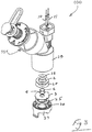
- the aerosol generator comprises a vibratable member such as a vibratable aperture plate 1, a vibration generator 2, and a support washer 3.
- the vibration generator 2 in this case comprises an annular piezoelectric element ("piezo") 2 having a first or upper surface and a second or lower surface.
- the piezo 2 is supported by the washer 3.
- the aperture plate 1 is supported by the support washer 3.
- a braze ring 4 is also provided.
- liquid to be aerosolised is received at a first upper surface of the aperture plate 1 and the piezo 2 is activated. Aerosolised liquid is generated at the second or lower surface of the aperture plate 1 by ejecting droplets of liquid upon activation of the piezo 2.
- the apertures in the aperture plate 1 are sized to aerosolise the liquid such that the majority of the droplets have a size of less than 6 micrometers.
- the vibratable member could be non-planar, and may be dome-shaped in geometry.
- first conducting pin 10 is in direct contact with the upper surface of the piezo 2.
- the second conducting pin 11 is in electrical contact with the upper surface of the support washer 3 via conductive adhesive 20 on a tab 103 of the support washer 3.
- the washer 3 and the conductive adhesive 20 are in turn is in electrical contact with the lower surface of the piezo 2. This arrangement is best illustrated in Figs. 4 to 6 .
- the support washer 3 in turn engages against a lower O-ring 25 which is housed in a groove 26 of a support housing 27.
- the support washer 3 also engages against an upper O-ring 28 in the upper part 29 of the main housing.
- the washer 3 is sandwiched between the upper O ring 28 and the lower O ring 25.
- This subassembly is in turn sandwiched between the upper housing 29 and the lower retainer clip 27.
- the arrangement of the lower retaining clip 27 provided uniform support around the support member 3, counter-balanced by the support forces applied via the O-ring 28 and the pins 10 and 11. This helps to achieve consistent operation of the aerosol generator 100, with reduced risk of fatigue in the seal between the plate 1 and the support washer 2, and a predictable plate vibration response to the applied electrical drive.
- both spring pins 10, 11 are the same and are placed in the same direction of orientation.
- the second spring pin 11 By attaching the piezo 2 to the support washer 3 using an electrically conductive means, the second spring pin 11 provides electrical communication to the underside of the piezo 2 through the top surface of the washer 3.
- the first spring pin 10 provides electrical conduction through the top surface of the piezo 2.
- electrical spring pins 10, 11 are used to connect directly between the female end of a detachable cable and the electrical surfaces of the piezoelectric generator 2. No soldering is required and the use of such pins facilitates assembly by automatic means.
- the electrically conductive liquid adhesive 20 is used to attach the underside of the piezo 2 to the washer 3. This is applied by automatic means.
- the viscosity, rheology, application rate, bead thickness, pressure of support washer/piezo contact are optimised to facilitate application of the conductive liquid adhesive by automatic means, both in the annular pattern and as a pad on the tab 103.
- Such adhesives may be cured at normal temperature or may require exposure to higher predetermined temperatures for a preset period of time to form a strong bonding attachment. The optimum bonding attachment is achieved when the adhesive is cured to provide optimum strength condition.
- Epoxies are particularly suited for this application and more particularly those with tensile moduli in the range of 300 to 10,000 MPa and more typically in the range of 2,000 - 7,000 MPa. Such materials have resistances in the order of 1 milliohm/cm2, but could be higher up to 100milliohm/cm2. Optimum mechanical properties are achieved when such adhesives are cured in the ranges of 3 minutes at 175 degrees centigrade to 240 minutes at 100 degrees centigrade. Typical hardness are in the range of 70 - 85 Shore D (ASTM D2240).
- the piezo 2 may alternatively be attached to the washer 3 by means of soldering by automatic means to provide an electrically conductive path between the top of the washer and the bottom of the piezo 2.
- this solution is not part of the invention.
- the interfacial electrical connection between the spring contact surface and the surface of the support washer 3 and the piezo 2 will be in pressure contact rather than mechanically connected together as with soldered joints.
- the interfacial connection between the spring pin contact area and the surface of the washer and piezo are critical.
- Nebulisers incorporating the aerosol generator of the invention must be able to perform in a wide range of modes of use. Such nebulizers are often used intermittently over a 28 day period or can be used continuously for up to 7 days.
- a number of undesirable mechanisms can occur such as oxidisation, corrosion mechanism, galvanic corrosion, mechanical vibrations, fretting wear to cause loss of electrical contact at the interface.
- each pin 10, 11 comprises a plunger 30, a spring 31 and a barrel 32.
- the spring contact force exerted by the spring pin is approximately between 1.3 and 3 Newtons which helps to reduce fretting wear as there is less pin bounce on the surface.
- Choosing pin materials of a low electrical resistivity such as Beryllium Copper alloy (BeCu), Nickel (Ni), or Copper Zinc alloy (CuZn) and stainless steel (SS 303) contributes to increased electrical conductivity.
- Barrel materials such as copper, brass and bronze alloys exhibit good electrical conductivity as well as good corrosion resistance and mechanical strength and are suitable for this application.
- Metallic coatings to prevent oxidisation of the interfacial surfaces such as Gold (Ag) over Nickel (Ni), also contribute to increased electrical conductivity. Coatings of 1 - 3 microns of gold over 3 microns of Nickel undercoat are particularly suitable.
- Spring parent materials can consist of Music Wire (ASTM A 228) and 304 Stainless Steel.
- Metallic coatings such as .05 microns of Gold over a 0.05 micron Nickel undercoat are especially suitable
- a conventional semi-hemispherical pin head has the disadvantage of not being able to expose new effective contacting surfaces.
- a vibrating multipoint contact pin head 50 as illustrated in Fig. 9 has the considerable advantage of being able to mechanically expose new areas for good electrical connection thus breaking down any oxidisation layers which can cause an insulation barrier.
- the multipoint contact pin increases the potential electrical contact surface area.
- the increased number of contact points, (which can vary in some embodiments from 7 - 14) act as a fail safe, if one contact becomes compromised the other contacts will form the required electrical contact.
- the addition of the multipoints rather than a semi-hemispherical or flat contacting spring pin surface increases the specific force at these interfacial points, reducing the potential for undesirable fretting wear, and causing the multipoints to engage new micro surfaces.
- Fig 10 shows another multipoint head 60 having seven points 61, with a V angle between of 55°, giving a point angle of 62.5°.
- the retainer and sealing arrangement also contribute to the above features to help ensure reliable operation.
- the retainer 27 and O-ring 25 provide comprehensive and uniform support directly below the piezo 2, while the smaller-diameter O-ring 28 transmits support forces from above closer to the circumference of the membrane 1 where it is supported by the support member 3.
- the elevated temperatures to effect a good joint bond can have an undesirable effect on any plating applied to the washer 3, which is typically Stainless Steel or Hastelloy. It is not possible to apply plating afterwards as it is difficult to mask off the aperture plate to prevent the ingress of conductive plating materials such as silver, gold, nickel or such like into the apertures.
- One way of overcoming this is to apply a conductive adhesive similar to the adhesive 20 that bonds the piezo 2 to the support washer 3. This can be applied by automatic means as part of the process of application to attach the piezo 2. It is not required on top of the piezo 2 to maintain conductivity with the spring pin 10 as such elements are typically silver coated.
- a particular current and voltage is required to drive the nebulizer 100 at the desired frequency to generate the optimum aerosol range [2.5- 6.5 ⁇ m particle size and flow rates between 0.1 and 2 ml/min] Voltages are typically 12V and the nebulizer is driven at 128 kHz.
- the multipointed spring pin 50 makes excellent electrical contact with the piezo 2 and the washer 3, achieving a uniform performance in which an aerosol plume has the desired characteristics of particle size and flow rate.
- the piezo is annular it ensures uniform radial vibration, which allows the core to work at its optimum mode of vibration.
- This symmetrical arrangement allows the aperture plate to move perpendicular to the piezo in a uniform and consistent manner, with a uniform forces applied around its circumference.
- the pins do not interfere with the mode of vibration.
- Their springs act as dampeners which ensure that these electrical connectors do not impact on the core's natural frequency. They add additional mass through a normal reaction to the core's movement, this normal reaction being absorbed via the pogo pin spring.
- the pin 11 has conductive glue between itself and the main body of the support washer 3, fretting and resulting intermittency issues are avoided, and there is improved electrical connection.
- the use of a conductive glue reduces the potential of increased contact resistance which is a known indicator to electrical contact fatigue. Also, the use of multiple contact points 50 increases the potential electrical contact area.
- the invention is used in the manufacture of aerosol generators which require electrical connection which have demanding requirements and which are required to be manufactured in high volumes without the use of laborious hand soldering.
Landscapes
- Health & Medical Sciences (AREA)
- Engineering & Computer Science (AREA)
- Life Sciences & Earth Sciences (AREA)
- Animal Behavior & Ethology (AREA)
- Anesthesiology (AREA)
- Biomedical Technology (AREA)
- Heart & Thoracic Surgery (AREA)
- Hematology (AREA)
- Veterinary Medicine (AREA)
- Public Health (AREA)
- General Health & Medical Sciences (AREA)
- Pulmonology (AREA)
- Bioinformatics & Cheminformatics (AREA)
- Special Spraying Apparatus (AREA)
- Apparatuses For Generation Of Mechanical Vibrations (AREA)
- Manipulator (AREA)
Claims (11)
- Générateur d'aérosol (100) comprenant :un élément apte à vibrer (1) ayant des ouvertures dans celui-ci ;un élément générateur de vibration (2), ce par quoi l'excitation de l'élément générateur de vibration (2) entraîne un mouvement de l'élément apte à vibrer (1) ;un élément de support (3), l'élément générateur de vibration (2) et l'élément apte à vibrer (1) étant montés sur l'élément de support ;une première broche conductrice de courant électrique (10) qui vient en prise avec une première surface de l'élément générateur de vibration (2) ;une deuxième broche conductrice de courant électrique (11) pour conduire du courant électrique vers une deuxième surface de l'élément générateur de vibration (2) ;où chacune des broches conductrices (10, 11) comprend une broche-ressort ;où l'élément générateur de vibration (2) et l'élément de support (3) sont annulaires,où la deuxième surface de l'élément générateur de vibration (2) est montée sur l'élément de support (3), et la deuxième broche conductrice (11) vient en prise avec l'élément de support (3), etl'élément générateur de vibration (2) est monté sur l'élément de support (3) au moyen d'un adhésif électriquement conducteur (20),caractérisé en ce quel'élément de support (3) inclut un substrat et un film (21) et la deuxième broche conductrice (11) est en contact avec ledit film (21), etle substrat de l'élément de support (3) comprend une rondelle en acier.
- Générateur d'aérosol selon la revendication 1, où le film (21) est un adhésif durci.
- Générateur d'aérosol selon la revendication 2, où l'adhésif (20) comprend un époxy.
- Générateur d'aérosol selon l'une quelconque des revendications 1 à 3, où le film (21) a une dureté comprise dans la plage de 70 à 85 Shore D.
- Générateur d'aérosol selon l'une quelconque des revendications 1 à 4, où le film (21) a un module de traction compris dans la plage de 2 000 à 7 000 MPa.
- Générateur d'aérosol selon l'une quelconque des revendications 1 à 5, où le film (21) est du même matériau que ledit adhésif (20) au moyen duquel l'élément générateur de vibration (2) est monté sur l'élément de support (3).
- Générateur d'aérosol selon l'une quelconque des revendications précédentes, où ledit film (21) est sous la forme d'un tampon discret sur une languette d'extension (103) du substrat d'élément de support.
- Générateur d'aérosol selon la revendication 7, où ledit film (21) sur la languette d'extension (103) est espacé dudit adhésif (20) sous l'élément générateur de vibration (2) qui fixe l'élément générateur de vibration à l'élément de support (3).
- Générateur d'aérosol selon l'une quelconque des revendications précédentes, comprenant en outre un dispositif de retenue supportant un ensemble de l'élément de support (3), de l'élément générateur de vibration (2) et de l'élément apte à vibrer (1) ; où le dispositif de retenue vient en prise avec un côté inférieur de l'élément de support (3) par le biais d'un joint annulaire (25) et vient en prise avec une surface supérieure de l'élément de support par le biais d'un joint annulaire d'équilibrage supérieur (28).
- Générateur d'aérosol selon la revendication 9, où le joint annulaire supérieur (28) est adjacent au bord de l'élément apte à vibrer (1) et a une dimension radiale plus petite que le joint annulaire inférieur (25).
- Générateur d'aérosol selon l'une ou l'autre des revendications 9 ou 10, où le joint annulaire inférieur (25) est en contact avec l'élément de support (3) au niveau d'un emplacement situé sous l'élément générateur de vibration (2), et le joint annulaire supérieur (28) est en contact avec l'élément de support latéralement à l'intérieur de l'élément générateur de vibration (2).
Priority Applications (3)
| Application Number | Priority Date | Filing Date | Title |
|---|---|---|---|
| EP20207577.6A EP3797874B1 (fr) | 2010-10-04 | 2011-10-03 | Générateur d'aérosol |
| PL17197100T PL3308865T3 (pl) | 2010-10-04 | 2011-10-03 | Generator aerozolu |
| EP25215387.9A EP4672508A3 (fr) | 2010-10-04 | 2011-10-03 | Générateur d'aérosol |
Applications Claiming Priority (5)
| Application Number | Priority Date | Filing Date | Title |
|---|---|---|---|
| US38950210P | 2010-10-04 | 2010-10-04 | |
| EP11770168.0A EP2624967B1 (fr) | 2010-10-04 | 2011-10-03 | Générateur d'aérosol |
| PCT/IE2011/000054 WO2012046220A1 (fr) | 2010-10-04 | 2011-10-03 | Générateur d'aérosol |
| EP15186028.5A EP2982445B1 (fr) | 2010-10-04 | 2011-10-03 | Générateur d'aérosol |
| EP17155020.5A EP3181243B1 (fr) | 2010-10-04 | 2011-10-03 | Générateur d'aérosol |
Related Parent Applications (5)
| Application Number | Title | Priority Date | Filing Date |
|---|---|---|---|
| EP11770168.0A Division EP2624967B1 (fr) | 2010-10-04 | 2011-10-03 | Générateur d'aérosol |
| EP17155020.5A Division EP3181243B1 (fr) | 2010-10-04 | 2011-10-03 | Générateur d'aérosol |
| EP17155020.5A Division-Into EP3181243B1 (fr) | 2010-10-04 | 2011-10-03 | Générateur d'aérosol |
| EP15186028.5A Division EP2982445B1 (fr) | 2010-10-04 | 2011-10-03 | Générateur d'aérosol |
| EP15186028.5A Division-Into EP2982445B1 (fr) | 2010-10-04 | 2011-10-03 | Générateur d'aérosol |
Related Child Applications (2)
| Application Number | Title | Priority Date | Filing Date |
|---|---|---|---|
| EP20207577.6A Division EP3797874B1 (fr) | 2010-10-04 | 2011-10-03 | Générateur d'aérosol |
| EP25215387.9A Division EP4672508A3 (fr) | 2010-10-04 | 2011-10-03 | Générateur d'aérosol |
Publications (2)
| Publication Number | Publication Date |
|---|---|
| EP3308865A1 EP3308865A1 (fr) | 2018-04-18 |
| EP3308865B1 true EP3308865B1 (fr) | 2020-12-16 |
Family
ID=44801045
Family Applications (7)
| Application Number | Title | Priority Date | Filing Date |
|---|---|---|---|
| EP17197100.5A Active EP3308865B1 (fr) | 2010-10-04 | 2011-10-03 | Générateur d'aérosol |
| EP17197095.7A Active EP3308864B1 (fr) | 2010-10-04 | 2011-10-03 | Générateur d'aérosol |
| EP25215387.9A Pending EP4672508A3 (fr) | 2010-10-04 | 2011-10-03 | Générateur d'aérosol |
| EP15186028.5A Active EP2982445B1 (fr) | 2010-10-04 | 2011-10-03 | Générateur d'aérosol |
| EP20207577.6A Active EP3797874B1 (fr) | 2010-10-04 | 2011-10-03 | Générateur d'aérosol |
| EP17155020.5A Active EP3181243B1 (fr) | 2010-10-04 | 2011-10-03 | Générateur d'aérosol |
| EP11770168.0A Revoked EP2624967B1 (fr) | 2010-10-04 | 2011-10-03 | Générateur d'aérosol |
Family Applications After (6)
| Application Number | Title | Priority Date | Filing Date |
|---|---|---|---|
| EP17197095.7A Active EP3308864B1 (fr) | 2010-10-04 | 2011-10-03 | Générateur d'aérosol |
| EP25215387.9A Pending EP4672508A3 (fr) | 2010-10-04 | 2011-10-03 | Générateur d'aérosol |
| EP15186028.5A Active EP2982445B1 (fr) | 2010-10-04 | 2011-10-03 | Générateur d'aérosol |
| EP20207577.6A Active EP3797874B1 (fr) | 2010-10-04 | 2011-10-03 | Générateur d'aérosol |
| EP17155020.5A Active EP3181243B1 (fr) | 2010-10-04 | 2011-10-03 | Générateur d'aérosol |
| EP11770168.0A Revoked EP2624967B1 (fr) | 2010-10-04 | 2011-10-03 | Générateur d'aérosol |
Country Status (7)
| Country | Link |
|---|---|
| US (9) | US9289792B2 (fr) |
| EP (7) | EP3308865B1 (fr) |
| DE (2) | DE202011110785U1 (fr) |
| ES (1) | ES3059859T3 (fr) |
| NO (1) | NO3181243T3 (fr) |
| PL (3) | PL3308864T3 (fr) |
| WO (1) | WO2012046220A1 (fr) |
Families Citing this family (44)
| Publication number | Priority date | Publication date | Assignee | Title |
|---|---|---|---|---|
| EP3308865B1 (fr) * | 2010-10-04 | 2020-12-16 | Stamford Devices Limited | Générateur d'aérosol |
| JP5984359B2 (ja) * | 2010-11-09 | 2016-09-06 | 住友化学株式会社 | 超音波霧化ユニット |
| ES2602318T3 (es) | 2011-12-29 | 2017-02-20 | Sumitomo Chemical Company Limited | Dispositivo de atomización ultrasónica y método de control de plagas |
| JP5981194B2 (ja) | 2012-03-30 | 2016-08-31 | 住友化学株式会社 | 霧化装置 |
| WO2013164253A1 (fr) | 2012-05-03 | 2013-11-07 | Stamford Devices Limited | Nébuliseur |
| GB201312263D0 (en) * | 2013-07-09 | 2013-08-21 | The Technology Partnership Plc | Separable membrane improvements |
| CN105592935B (zh) | 2013-07-24 | 2018-10-16 | 斯坦福设备有限公司 | 喷雾器振动孔板驱动频率控制及监测 |
| US20150053786A1 (en) * | 2013-08-21 | 2015-02-26 | Trimble Navigation Limited | Intelligent precision irrigation system |
| US10092712B2 (en) | 2013-11-04 | 2018-10-09 | Stamford Devices Limited | Aerosol delivery system |
| EP2868339B1 (fr) | 2013-11-04 | 2016-10-19 | Stamford Devices Limited | Système d'administration d'un aérosol |
| TWI527629B (zh) * | 2014-02-14 | 2016-04-01 | 德技股份有限公司 | 霧化器噴頭 |
| TWI595930B (zh) * | 2014-06-25 | 2017-08-21 | 達爾生技股份有限公司 | 霧化裝置及霧化模組 |
| DE102014114009A1 (de) * | 2014-09-26 | 2016-03-31 | Stefan Kern | Vorrichtung zur Befeuchtung der Atemluft eines Benutzers und dessen Verwendung |
| US9476603B2 (en) * | 2014-12-12 | 2016-10-25 | Dong Guan Song Wei Electric Technology Co., Ltd | Heater with humidifying device |
| US20170043106A1 (en) * | 2015-03-23 | 2017-02-16 | Stamford Devices Limited | Aerosol generator |
| EP3127616B1 (fr) * | 2015-08-03 | 2017-10-18 | PARI Pharma GmbH | Procédé de fabrication d'une tête vibrante pour un générateur d'aérosol et tête vibrante pour un générateur d'aérosol |
| CA3003056C (fr) * | 2015-11-02 | 2023-09-26 | Philip Morris Products S.A. | Systeme de generation d'aerosol comprenant un element pouvant etre mis en vibration |
| US11376375B2 (en) * | 2016-02-08 | 2022-07-05 | Koninklijke Philips N.V. | Aerosol generator |
| WO2018007245A1 (fr) | 2016-07-04 | 2018-01-11 | Stamford Devices Limited | Générateur d'aérosol |
| US10987474B2 (en) | 2017-03-23 | 2021-04-27 | Stamford Devices Ltd. | Retrofit aerosol delivery system and method |
| EP3672734B1 (fr) | 2017-08-25 | 2021-09-22 | Stamford Devices Limited | Protection d'une plaque munie d'orifice durant la génération d'un aérosol |
| DE102017124742A1 (de) * | 2017-10-23 | 2019-04-25 | Nebu-Tec Med. Produkte Eike Kern Gmbh | Automatische Medikamentendosierung bei Verneblern |
| EP3723912B1 (fr) | 2017-12-14 | 2022-08-24 | Stamford Devices Limited | Montage d'une plaque d'ouverture de générateur d'aérosol sur un support |
| CN110394268B (zh) * | 2018-04-25 | 2021-07-02 | 微邦科技股份有限公司 | 微雾生成装置及微雾产生器 |
| CN110393837B (zh) | 2018-04-25 | 2022-03-29 | 微邦科技股份有限公司 | 微雾产生器及雾化模块 |
| CN108379702B (zh) * | 2018-05-11 | 2019-10-15 | 泰安大陆医疗器械有限公司 | 医用雾化器 |
| CN217014957U (zh) | 2019-08-02 | 2022-07-22 | 斯坦福设备有限公司 | 雾化器控制装置和雾化器 |
| CA3146251A1 (fr) * | 2019-08-02 | 2021-02-11 | Stamford Devices Limited | Administration buccale d'aerosol |
| USD899584S1 (en) * | 2019-08-13 | 2020-10-20 | Convexity Scientific Inc. | Reservoir piezo disk assembly for a nebulizer |
| MX2022003715A (es) * | 2019-09-26 | 2022-07-11 | Vapotherm Inc | Nebulizador montado en cánula interna. |
| EP4126390B1 (fr) | 2020-03-24 | 2025-09-24 | Stamford Devices Limited | Nébuliseur à plaque perforée vibrante |
| US12138382B2 (en) | 2020-07-14 | 2024-11-12 | Stamford Devices Limited | Vaccine administration apparatus and method |
| JP7543558B2 (ja) | 2020-10-12 | 2024-09-02 | ヴェクトュラ・デリヴァリー・ディヴァイスィズ・リミテッド | 吸入装置のためのエアロゾル発生器 |
| CA3197062A1 (fr) | 2020-10-16 | 2022-04-21 | Vectura Delivery Devices Limited | Methode de detection de la presence de liquide dans un nebuliseur a membrane vibrante |
| CN116600842B (zh) | 2020-12-16 | 2025-11-25 | 维克多瑞传送设备有限公司 | 用于检测振动膜喷雾器中液体的存在的方法 |
| EP4015094A1 (fr) | 2020-12-16 | 2022-06-22 | Vectura Delivery Devices Limited | Nébuliseur à membrane vibrante |
| TWI747773B (zh) * | 2021-03-25 | 2021-11-21 | 心誠鎂行動醫電股份有限公司 | 給藥容器以及霧化裝置 |
| USD1062035S1 (en) | 2021-05-21 | 2025-02-11 | Stamford Devices Limited | Aerosol delivery device with mouthpiece |
| EP4355397B1 (fr) | 2021-06-16 | 2025-06-25 | Stamford Devices Limited | Système de ventilateur |
| EP4197646A1 (fr) | 2021-12-17 | 2023-06-21 | Stamford Devices Limited | Pulvérisateur avec détection de panache |
| WO2023110407A1 (fr) | 2021-12-17 | 2023-06-22 | Stamford Devices Limited | Nébuliseur à détection de panache |
| CN114190596A (zh) * | 2021-12-21 | 2022-03-18 | 深圳摩尔雾化健康医疗科技有限公司 | 微孔雾化组件及超声雾化装置 |
| EP4612346A1 (fr) | 2022-11-03 | 2025-09-10 | Stamford Devices Limited | Procédé de fabrication de plaques à ouvertures de nébuliseur |
| ES2973682B2 (es) * | 2022-11-10 | 2025-10-01 | Zobele Espana Sa | Dispositivo para la difusión de sustancias volátiles |
Family Cites Families (36)
| Publication number | Priority date | Publication date | Assignee | Title |
|---|---|---|---|---|
| DE3533227A1 (de) | 1984-09-27 | 1986-04-03 | Feinmetall Gmbh, 7033 Herrenberg | Federkontaktstift |
| US4976259A (en) * | 1986-12-22 | 1990-12-11 | Mountain Medical Equipment, Inc. | Ultrasonic nebulizer |
| DE3820795A1 (de) | 1988-06-20 | 1989-12-21 | Ingun Pruefmittelbau Gmbh | Gefederter kontaktstift zum pruefen von prueflingen |
| EP0480615B1 (fr) * | 1990-10-11 | 1996-02-14 | Kohji Toda | Pulvérisateur à ultrasons |
| US5435282A (en) | 1994-05-19 | 1995-07-25 | Habley Medical Technology Corporation | Nebulizer |
| US6205999B1 (en) * | 1995-04-05 | 2001-03-27 | Aerogen, Inc. | Methods and apparatus for storing chemical compounds in a portable inhaler |
| AU1820900A (en) * | 1998-11-25 | 2000-06-13 | Rika Electronics International, Inc. | Electrical contact system |
| US6530370B1 (en) * | 1999-09-16 | 2003-03-11 | Instrumentation Corp. | Nebulizer apparatus |
| US6539937B1 (en) * | 2000-04-12 | 2003-04-01 | Instrumentarium Corp. | Method of maximizing the mechanical displacement of a piezoelectric nebulizer apparatus |
| US8336545B2 (en) * | 2000-05-05 | 2012-12-25 | Novartis Pharma Ag | Methods and systems for operating an aerosol generator |
| US6769626B1 (en) * | 2000-10-30 | 2004-08-03 | Instrumentarium Corp. | Device and method for detecting and controlling liquid supply to an apparatus discharging liquids |
| US6554201B2 (en) * | 2001-05-02 | 2003-04-29 | Aerogen, Inc. | Insert molded aerosol generator and methods |
| US6732944B2 (en) * | 2001-05-02 | 2004-05-11 | Aerogen, Inc. | Base isolated nebulizing device and methods |
| DE10122065B4 (de) | 2001-05-07 | 2007-10-04 | Pari GmbH Spezialisten für effektive Inhalation | Vorrichtung zur Erzeugung von Flüssigkeitströpfchen mit einer in Schwingungen versetzten Membran |
| DE60227277D1 (de) * | 2001-09-24 | 2008-08-07 | Rika Denshi America Inc | Elektrische testsonden und verfahren zu ihrer herstellung |
| DE50102690D1 (de) | 2001-10-18 | 2004-07-29 | Pari Gmbh | Inhalationstherapievorrichtung |
| MXPA04006629A (es) * | 2002-01-07 | 2004-11-10 | Aerogen Inc | Aparatos y metodos para nebulizar fluidos para inhalacion. |
| US6978779B2 (en) * | 2002-04-19 | 2005-12-27 | Instrumentarium Corp. | Vibrating element liquid discharging apparatus having gas pressure sensing |
| AU2003256253A1 (en) * | 2002-05-20 | 2003-12-02 | Aerogen, Inc. | Aerosol for medical treatment and methods |
| US20070044792A1 (en) * | 2005-08-30 | 2007-03-01 | Aerogen, Inc. | Aerosol generators with enhanced corrosion resistance |
| US6843430B2 (en) * | 2002-05-24 | 2005-01-18 | S. C. Johnson & Son, Inc. | Low leakage liquid atomization device |
| JP4089976B2 (ja) | 2004-05-17 | 2008-05-28 | リーノ アイエヌディー.インコーポレイテッド | 大電流用プローブ |
| DE102005006375B4 (de) | 2005-02-11 | 2007-10-11 | Pari GmbH Spezialisten für effektive Inhalation | Aerosolerzeugungsvorrichtung für Inhalationstherapiegeräte |
| DE102005006374B3 (de) | 2005-02-11 | 2006-07-20 | Pari GmbH Spezialisten für effektive Inhalation | Aerosolerzeugungsvorrichtung und Inhalationstherapiegerät mit einer derartigen Vorrichtung |
| US7954730B2 (en) * | 2005-05-02 | 2011-06-07 | Hong Kong Piezo Co. Ltd. | Piezoelectric fluid atomizer apparatuses and methods |
| DE102006030833A1 (de) | 2006-07-04 | 2008-01-10 | Pari GmbH Spezialisten für effektive Inhalation | Verfahren und Vorrichtung für die Reinigung der Verneblermembran in einem Inhalationstherapiegerät |
| KR100843203B1 (ko) * | 2006-09-08 | 2008-07-02 | 삼성전자주식회사 | 포고 핀 및 그 포고 핀을 포함한 반도체 소자 테스트용콘택터 |
| US20090235925A1 (en) * | 2007-03-28 | 2009-09-24 | John Sylvester Power | Aerosolisation system |
| US20090242660A1 (en) * | 2008-03-25 | 2009-10-01 | Quatek Co., Ltd. | Medical liquid droplet apparatus |
| US20090261851A1 (en) | 2008-04-18 | 2009-10-22 | Antares Advanced Test Technologies, Inc. | Spring probe |
| TWM365789U (en) * | 2009-02-25 | 2009-10-01 | Health & Amp Life Co Ltd | Droplet generation apparatus |
| DE102009026636B4 (de) | 2009-06-02 | 2011-04-14 | Pari Pharma Gmbh | Verfahren zum Verschweißen einer Membran mit einem Träger bei der Herstellung eines Membranverneblers |
| AU2010320709B2 (en) * | 2009-11-18 | 2015-04-09 | Reckitt Benckiser Llc | Ultrasonic surface treatment device and method |
| CN102711880B (zh) * | 2010-01-11 | 2015-11-25 | 皇家飞利浦电子股份有限公司 | 用于气雾剂产生器械的磁力联接 |
| EP2569033B1 (fr) * | 2010-05-13 | 2017-11-15 | Nortev Limited | Système générateur d'aérosol |
| EP3308865B1 (fr) * | 2010-10-04 | 2020-12-16 | Stamford Devices Limited | Générateur d'aérosol |
-
2011
- 2011-10-03 EP EP17197100.5A patent/EP3308865B1/fr active Active
- 2011-10-03 EP EP17197095.7A patent/EP3308864B1/fr active Active
- 2011-10-03 EP EP25215387.9A patent/EP4672508A3/fr active Pending
- 2011-10-03 PL PL17197095T patent/PL3308864T3/pl unknown
- 2011-10-03 EP EP15186028.5A patent/EP2982445B1/fr active Active
- 2011-10-03 NO NO17155020A patent/NO3181243T3/no unknown
- 2011-10-03 EP EP20207577.6A patent/EP3797874B1/fr active Active
- 2011-10-03 ES ES20207577T patent/ES3059859T3/es active Active
- 2011-10-03 EP EP17155020.5A patent/EP3181243B1/fr active Active
- 2011-10-03 PL PL20207577.6T patent/PL3797874T3/pl unknown
- 2011-10-03 US US13/251,924 patent/US9289792B2/en active Active
- 2011-10-03 EP EP11770168.0A patent/EP2624967B1/fr not_active Revoked
- 2011-10-03 DE DE202011110785.3U patent/DE202011110785U1/de not_active Expired - Lifetime
- 2011-10-03 WO PCT/IE2011/000054 patent/WO2012046220A1/fr not_active Ceased
- 2011-10-03 PL PL17197100T patent/PL3308865T3/pl unknown
- 2011-10-03 DE DE202011111143.5U patent/DE202011111143U1/de not_active Expired - Lifetime
-
2016
- 2016-02-19 US US15/048,358 patent/US10092924B2/en active Active
-
2017
- 2017-03-31 US US15/476,461 patent/US10399109B2/en active Active
- 2017-03-31 US US15/476,242 patent/US10322432B2/en active Active
- 2017-03-31 US US15/476,369 patent/US10695787B2/en active Active
-
2019
- 2019-04-22 US US16/390,750 patent/US11904340B2/en active Active
-
2021
- 2021-04-12 US US17/227,559 patent/US11446695B2/en active Active
-
2022
- 2022-08-15 US US17/888,334 patent/US11648580B2/en active Active
-
2024
- 2024-01-16 US US18/413,487 patent/US20250229286A1/en active Pending
Non-Patent Citations (1)
| Title |
|---|
| None * |
Also Published As
Similar Documents
| Publication | Publication Date | Title |
|---|---|---|
| US11648580B2 (en) | Aerosol generator with electrical power conducting pins | |
| EP2568175B1 (fr) | Dispositif de contrôle de fluides | |
| CN113909844B (zh) | 气雾剂产生器孔板到支撑件的安装 | |
| JPWO2008041484A1 (ja) | 弾性接触子を用いた金属端子間の接合方法 | |
| JP4793203B2 (ja) | 異方導電性コネクターおよびこの異方導電性コネクターを用いた被検査体の検査方法 | |
| CN106448642B (zh) | 压电发声体 | |
| JP2000331726A (ja) | 電気コネクタ | |
| JP2000091051A (ja) | 半導体試験装置 | |
| HK40066789A (zh) | 气雾剂产生器孔板到支撑件的安装 | |
| HK40066789B (zh) | 气雾剂产生器孔板到支撑件的安装 | |
| JP2002058263A (ja) | 圧電アクチュエータ |
Legal Events
| Date | Code | Title | Description |
|---|---|---|---|
| PUAI | Public reference made under article 153(3) epc to a published international application that has entered the european phase |
Free format text: ORIGINAL CODE: 0009012 |
|
| STAA | Information on the status of an ep patent application or granted ep patent |
Free format text: STATUS: THE APPLICATION HAS BEEN PUBLISHED |
|
| AC | Divisional application: reference to earlier application |
Ref document number: 3181243 Country of ref document: EP Kind code of ref document: P Ref document number: 2982445 Country of ref document: EP Kind code of ref document: P Ref document number: 2624967 Country of ref document: EP Kind code of ref document: P |
|
| AK | Designated contracting states |
Kind code of ref document: A1 Designated state(s): AL AT BE BG CH CY CZ DE DK EE ES FI FR GB GR HR HU IE IS IT LI LT LU LV MC MK MT NL NO PL PT RO RS SE SI SK SM TR |
|
| STAA | Information on the status of an ep patent application or granted ep patent |
Free format text: STATUS: REQUEST FOR EXAMINATION WAS MADE |
|
| 17P | Request for examination filed |
Effective date: 20180815 |
|
| RBV | Designated contracting states (corrected) |
Designated state(s): AL AT BE BG CH CY CZ DE DK EE ES FI FR GB GR HR HU IE IS IT LI LT LU LV MC MK MT NL NO PL PT RO RS SE SI SK SM TR |
|
| STAA | Information on the status of an ep patent application or granted ep patent |
Free format text: STATUS: EXAMINATION IS IN PROGRESS |
|
| 17Q | First examination report despatched |
Effective date: 20200120 |
|
| GRAP | Despatch of communication of intention to grant a patent |
Free format text: ORIGINAL CODE: EPIDOSNIGR1 |
|
| STAA | Information on the status of an ep patent application or granted ep patent |
Free format text: STATUS: GRANT OF PATENT IS INTENDED |
|
| INTG | Intention to grant announced |
Effective date: 20200707 |
|
| GRAS | Grant fee paid |
Free format text: ORIGINAL CODE: EPIDOSNIGR3 |
|
| GRAA | (expected) grant |
Free format text: ORIGINAL CODE: 0009210 |
|
| STAA | Information on the status of an ep patent application or granted ep patent |
Free format text: STATUS: THE PATENT HAS BEEN GRANTED |
|
| AC | Divisional application: reference to earlier application |
Ref document number: 2624967 Country of ref document: EP Kind code of ref document: P Ref document number: 3181243 Country of ref document: EP Kind code of ref document: P Ref document number: 2982445 Country of ref document: EP Kind code of ref document: P |
|
| AK | Designated contracting states |
Kind code of ref document: B1 Designated state(s): AL AT BE BG CH CY CZ DE DK EE ES FI FR GB GR HR HU IE IS IT LI LT LU LV MC MK MT NL NO PL PT RO RS SE SI SK SM TR |
|
| REG | Reference to a national code |
Ref country code: GB Ref legal event code: FG4D |
|
| REG | Reference to a national code |
Ref country code: DE Ref legal event code: R096 Ref document number: 602011069697 Country of ref document: DE |
|
| REG | Reference to a national code |
Ref country code: IE Ref legal event code: FG4D |
|
| REG | Reference to a national code |
Ref country code: AT Ref legal event code: REF Ref document number: 1345107 Country of ref document: AT Kind code of ref document: T Effective date: 20210115 |
|
| REG | Reference to a national code |
Ref country code: NL Ref legal event code: FP |
|
| REG | Reference to a national code |
Ref country code: SE Ref legal event code: TRGR |
|
| REG | Reference to a national code |
Ref country code: NO Ref legal event code: T2 Effective date: 20201216 |
|
| PG25 | Lapsed in a contracting state [announced via postgrant information from national office to epo] |
Ref country code: RS Free format text: LAPSE BECAUSE OF FAILURE TO SUBMIT A TRANSLATION OF THE DESCRIPTION OR TO PAY THE FEE WITHIN THE PRESCRIBED TIME-LIMIT Effective date: 20201216 Ref country code: FI Free format text: LAPSE BECAUSE OF FAILURE TO SUBMIT A TRANSLATION OF THE DESCRIPTION OR TO PAY THE FEE WITHIN THE PRESCRIBED TIME-LIMIT Effective date: 20201216 Ref country code: GR Free format text: LAPSE BECAUSE OF FAILURE TO SUBMIT A TRANSLATION OF THE DESCRIPTION OR TO PAY THE FEE WITHIN THE PRESCRIBED TIME-LIMIT Effective date: 20210317 |
|
| REG | Reference to a national code |
Ref country code: AT Ref legal event code: MK05 Ref document number: 1345107 Country of ref document: AT Kind code of ref document: T Effective date: 20201216 |
|
| PG25 | Lapsed in a contracting state [announced via postgrant information from national office to epo] |
Ref country code: LV Free format text: LAPSE BECAUSE OF FAILURE TO SUBMIT A TRANSLATION OF THE DESCRIPTION OR TO PAY THE FEE WITHIN THE PRESCRIBED TIME-LIMIT Effective date: 20201216 Ref country code: BG Free format text: LAPSE BECAUSE OF FAILURE TO SUBMIT A TRANSLATION OF THE DESCRIPTION OR TO PAY THE FEE WITHIN THE PRESCRIBED TIME-LIMIT Effective date: 20210316 |
|
| PG25 | Lapsed in a contracting state [announced via postgrant information from national office to epo] |
Ref country code: HR Free format text: LAPSE BECAUSE OF FAILURE TO SUBMIT A TRANSLATION OF THE DESCRIPTION OR TO PAY THE FEE WITHIN THE PRESCRIBED TIME-LIMIT Effective date: 20201216 |
|
| REG | Reference to a national code |
Ref country code: LT Ref legal event code: MG9D |
|
| PG25 | Lapsed in a contracting state [announced via postgrant information from national office to epo] |
Ref country code: SM Free format text: LAPSE BECAUSE OF FAILURE TO SUBMIT A TRANSLATION OF THE DESCRIPTION OR TO PAY THE FEE WITHIN THE PRESCRIBED TIME-LIMIT Effective date: 20201216 Ref country code: LT Free format text: LAPSE BECAUSE OF FAILURE TO SUBMIT A TRANSLATION OF THE DESCRIPTION OR TO PAY THE FEE WITHIN THE PRESCRIBED TIME-LIMIT Effective date: 20201216 Ref country code: CZ Free format text: LAPSE BECAUSE OF FAILURE TO SUBMIT A TRANSLATION OF THE DESCRIPTION OR TO PAY THE FEE WITHIN THE PRESCRIBED TIME-LIMIT Effective date: 20201216 Ref country code: EE Free format text: LAPSE BECAUSE OF FAILURE TO SUBMIT A TRANSLATION OF THE DESCRIPTION OR TO PAY THE FEE WITHIN THE PRESCRIBED TIME-LIMIT Effective date: 20201216 Ref country code: RO Free format text: LAPSE BECAUSE OF FAILURE TO SUBMIT A TRANSLATION OF THE DESCRIPTION OR TO PAY THE FEE WITHIN THE PRESCRIBED TIME-LIMIT Effective date: 20201216 Ref country code: PT Free format text: LAPSE BECAUSE OF FAILURE TO SUBMIT A TRANSLATION OF THE DESCRIPTION OR TO PAY THE FEE WITHIN THE PRESCRIBED TIME-LIMIT Effective date: 20210416 Ref country code: SK Free format text: LAPSE BECAUSE OF FAILURE TO SUBMIT A TRANSLATION OF THE DESCRIPTION OR TO PAY THE FEE WITHIN THE PRESCRIBED TIME-LIMIT Effective date: 20201216 |
|
| PG25 | Lapsed in a contracting state [announced via postgrant information from national office to epo] |
Ref country code: AT Free format text: LAPSE BECAUSE OF FAILURE TO SUBMIT A TRANSLATION OF THE DESCRIPTION OR TO PAY THE FEE WITHIN THE PRESCRIBED TIME-LIMIT Effective date: 20201216 |
|
| REG | Reference to a national code |
Ref country code: DE Ref legal event code: R097 Ref document number: 602011069697 Country of ref document: DE |
|
| PG25 | Lapsed in a contracting state [announced via postgrant information from national office to epo] |
Ref country code: IS Free format text: LAPSE BECAUSE OF FAILURE TO SUBMIT A TRANSLATION OF THE DESCRIPTION OR TO PAY THE FEE WITHIN THE PRESCRIBED TIME-LIMIT Effective date: 20210416 |
|
| PLBE | No opposition filed within time limit |
Free format text: ORIGINAL CODE: 0009261 |
|
| STAA | Information on the status of an ep patent application or granted ep patent |
Free format text: STATUS: NO OPPOSITION FILED WITHIN TIME LIMIT |
|
| PG25 | Lapsed in a contracting state [announced via postgrant information from national office to epo] |
Ref country code: IT Free format text: LAPSE BECAUSE OF FAILURE TO SUBMIT A TRANSLATION OF THE DESCRIPTION OR TO PAY THE FEE WITHIN THE PRESCRIBED TIME-LIMIT Effective date: 20201216 Ref country code: AL Free format text: LAPSE BECAUSE OF FAILURE TO SUBMIT A TRANSLATION OF THE DESCRIPTION OR TO PAY THE FEE WITHIN THE PRESCRIBED TIME-LIMIT Effective date: 20201216 |
|
| 26N | No opposition filed |
Effective date: 20210917 |
|
| PG25 | Lapsed in a contracting state [announced via postgrant information from national office to epo] |
Ref country code: DK Free format text: LAPSE BECAUSE OF FAILURE TO SUBMIT A TRANSLATION OF THE DESCRIPTION OR TO PAY THE FEE WITHIN THE PRESCRIBED TIME-LIMIT Effective date: 20201216 |
|
| PG25 | Lapsed in a contracting state [announced via postgrant information from national office to epo] |
Ref country code: ES Free format text: LAPSE BECAUSE OF FAILURE TO SUBMIT A TRANSLATION OF THE DESCRIPTION OR TO PAY THE FEE WITHIN THE PRESCRIBED TIME-LIMIT Effective date: 20201216 |
|
| PG25 | Lapsed in a contracting state [announced via postgrant information from national office to epo] |
Ref country code: SI Free format text: LAPSE BECAUSE OF FAILURE TO SUBMIT A TRANSLATION OF THE DESCRIPTION OR TO PAY THE FEE WITHIN THE PRESCRIBED TIME-LIMIT Effective date: 20201216 |
|
| PG25 | Lapsed in a contracting state [announced via postgrant information from national office to epo] |
Ref country code: IS Free format text: LAPSE BECAUSE OF FAILURE TO SUBMIT A TRANSLATION OF THE DESCRIPTION OR TO PAY THE FEE WITHIN THE PRESCRIBED TIME-LIMIT Effective date: 20210416 |
|
| REG | Reference to a national code |
Ref country code: BE Ref legal event code: MM Effective date: 20211031 |
|
| PG25 | Lapsed in a contracting state [announced via postgrant information from national office to epo] |
Ref country code: MC Free format text: LAPSE BECAUSE OF FAILURE TO SUBMIT A TRANSLATION OF THE DESCRIPTION OR TO PAY THE FEE WITHIN THE PRESCRIBED TIME-LIMIT Effective date: 20201216 |
|
| PG25 | Lapsed in a contracting state [announced via postgrant information from national office to epo] |
Ref country code: LU Free format text: LAPSE BECAUSE OF NON-PAYMENT OF DUE FEES Effective date: 20211003 Ref country code: BE Free format text: LAPSE BECAUSE OF NON-PAYMENT OF DUE FEES Effective date: 20211031 |
|
| PG25 | Lapsed in a contracting state [announced via postgrant information from national office to epo] |
Ref country code: HU Free format text: LAPSE BECAUSE OF FAILURE TO SUBMIT A TRANSLATION OF THE DESCRIPTION OR TO PAY THE FEE WITHIN THE PRESCRIBED TIME-LIMIT; INVALID AB INITIO Effective date: 20111003 Ref country code: CY Free format text: LAPSE BECAUSE OF FAILURE TO SUBMIT A TRANSLATION OF THE DESCRIPTION OR TO PAY THE FEE WITHIN THE PRESCRIBED TIME-LIMIT Effective date: 20201216 |
|
| P01 | Opt-out of the competence of the unified patent court (upc) registered |
Effective date: 20230427 |
|
| PG25 | Lapsed in a contracting state [announced via postgrant information from national office to epo] |
Ref country code: MK Free format text: LAPSE BECAUSE OF FAILURE TO SUBMIT A TRANSLATION OF THE DESCRIPTION OR TO PAY THE FEE WITHIN THE PRESCRIBED TIME-LIMIT Effective date: 20201216 |
|
| PG25 | Lapsed in a contracting state [announced via postgrant information from national office to epo] |
Ref country code: MT Free format text: LAPSE BECAUSE OF FAILURE TO SUBMIT A TRANSLATION OF THE DESCRIPTION OR TO PAY THE FEE WITHIN THE PRESCRIBED TIME-LIMIT Effective date: 20201216 |
|
| PGFP | Annual fee paid to national office [announced via postgrant information from national office to epo] |
Ref country code: NO Payment date: 20250813 Year of fee payment: 15 |
|
| PGFP | Annual fee paid to national office [announced via postgrant information from national office to epo] |
Ref country code: PL Payment date: 20250812 Year of fee payment: 15 |
|
| PGFP | Annual fee paid to national office [announced via postgrant information from national office to epo] |
Ref country code: GB Payment date: 20250808 Year of fee payment: 15 |
|
| PGFP | Annual fee paid to national office [announced via postgrant information from national office to epo] |
Ref country code: SE Payment date: 20250812 Year of fee payment: 15 |
|
| PGFP | Annual fee paid to national office [announced via postgrant information from national office to epo] |
Ref country code: IE Payment date: 20250808 Year of fee payment: 15 |
|
| REG | Reference to a national code |
Ref country code: CH Ref legal event code: U11 Free format text: ST27 STATUS EVENT CODE: U-0-0-U10-U11 (AS PROVIDED BY THE NATIONAL OFFICE) Effective date: 20251101 |
|
| PGFP | Annual fee paid to national office [announced via postgrant information from national office to epo] |
Ref country code: NL Payment date: 20251022 Year of fee payment: 15 |
|
| PGFP | Annual fee paid to national office [announced via postgrant information from national office to epo] |
Ref country code: DE Payment date: 20250915 Year of fee payment: 15 |
|
| PGFP | Annual fee paid to national office [announced via postgrant information from national office to epo] |
Ref country code: FR Payment date: 20251028 Year of fee payment: 15 |
|
| PGFP | Annual fee paid to national office [announced via postgrant information from national office to epo] |
Ref country code: TR Payment date: 20251001 Year of fee payment: 15 |
|
| PGFP | Annual fee paid to national office [announced via postgrant information from national office to epo] |
Ref country code: CH Payment date: 20251101 Year of fee payment: 15 |