EP3309078B1 - Luftfahrzeuggondel, die eine verbindung zwischen einer luftleitung und einer motorisierungsleitung umfasst - Google Patents
Luftfahrzeuggondel, die eine verbindung zwischen einer luftleitung und einer motorisierungsleitung umfasst Download PDFInfo
- Publication number
- EP3309078B1 EP3309078B1 EP17194690.8A EP17194690A EP3309078B1 EP 3309078 B1 EP3309078 B1 EP 3309078B1 EP 17194690 A EP17194690 A EP 17194690A EP 3309078 B1 EP3309078 B1 EP 3309078B1
- Authority
- EP
- European Patent Office
- Prior art keywords
- conduit
- sleeve
- rigidly connected
- nacelle
- linking
- Prior art date
- Legal status (The legal status is an assumption and is not a legal conclusion. Google has not performed a legal analysis and makes no representation as to the accuracy of the status listed.)
- Active
Links
Images

Classifications
-
- B—PERFORMING OPERATIONS; TRANSPORTING
- B64—AIRCRAFT; AVIATION; COSMONAUTICS
- B64D—EQUIPMENT FOR FITTING IN OR TO AIRCRAFT; FLIGHT SUITS; PARACHUTES; ARRANGEMENT OR MOUNTING OF POWER PLANTS OR PROPULSION TRANSMISSIONS IN AIRCRAFT
- B64D33/00—Arrangement in aircraft of power plant parts or auxiliaries not otherwise provided for
- B64D33/02—Arrangement in aircraft of power plant parts or auxiliaries not otherwise provided for of combustion air intakes
-
- B—PERFORMING OPERATIONS; TRANSPORTING
- B64—AIRCRAFT; AVIATION; COSMONAUTICS
- B64D—EQUIPMENT FOR FITTING IN OR TO AIRCRAFT; FLIGHT SUITS; PARACHUTES; ARRANGEMENT OR MOUNTING OF POWER PLANTS OR PROPULSION TRANSMISSIONS IN AIRCRAFT
- B64D29/00—Power-plant nacelles, fairings or cowlings
- B64D29/06—Attaching of nacelles, fairings or cowlings
-
- B—PERFORMING OPERATIONS; TRANSPORTING
- B64—AIRCRAFT; AVIATION; COSMONAUTICS
- B64D—EQUIPMENT FOR FITTING IN OR TO AIRCRAFT; FLIGHT SUITS; PARACHUTES; ARRANGEMENT OR MOUNTING OF POWER PLANTS OR PROPULSION TRANSMISSIONS IN AIRCRAFT
- B64D29/00—Power-plant nacelles, fairings or cowlings
- B64D29/02—Power-plant nacelles, fairings or cowlings associated with wings
-
- B—PERFORMING OPERATIONS; TRANSPORTING
- B64—AIRCRAFT; AVIATION; COSMONAUTICS
- B64D—EQUIPMENT FOR FITTING IN OR TO AIRCRAFT; FLIGHT SUITS; PARACHUTES; ARRANGEMENT OR MOUNTING OF POWER PLANTS OR PROPULSION TRANSMISSIONS IN AIRCRAFT
- B64D33/00—Arrangement in aircraft of power plant parts or auxiliaries not otherwise provided for
- B64D33/02—Arrangement in aircraft of power plant parts or auxiliaries not otherwise provided for of combustion air intakes
- B64D2033/0206—Arrangement in aircraft of power plant parts or auxiliaries not otherwise provided for of combustion air intakes comprising noise reduction means, e.g. acoustic liners
-
- B—PERFORMING OPERATIONS; TRANSPORTING
- B64—AIRCRAFT; AVIATION; COSMONAUTICS
- B64D—EQUIPMENT FOR FITTING IN OR TO AIRCRAFT; FLIGHT SUITS; PARACHUTES; ARRANGEMENT OR MOUNTING OF POWER PLANTS OR PROPULSION TRANSMISSIONS IN AIRCRAFT
- B64D33/00—Arrangement in aircraft of power plant parts or auxiliaries not otherwise provided for
- B64D33/02—Arrangement in aircraft of power plant parts or auxiliaries not otherwise provided for of combustion air intakes
- B64D2033/0266—Arrangement in aircraft of power plant parts or auxiliaries not otherwise provided for of combustion air intakes specially adapted for particular type of power plants
- B64D2033/0286—Arrangement in aircraft of power plant parts or auxiliaries not otherwise provided for of combustion air intakes specially adapted for particular type of power plants for turbofan engines
Definitions
- the present invention relates to an aircraft nacelle comprising a connection between a conduit of an air inlet and a conduit of an engine.
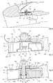
- an aircraft nacelle comprises at the front an air inlet 10 for channeling a flow of air towards a motorization 12.
- the longitudinal direction corresponds to the direction of the axis of the engine.
- a longitudinal plane is a plane that contains the axis of the engine.
- a transverse plane is a plane perpendicular to the axis of the engine.
- a radial direction is a direction perpendicular to the axis of the engine.
- the terms front and back refer to the flow direction of the airflow in the nacelle.
- the front is an area where the air flow enters the basket and the back to an area where the air flow out of the nacelle.
- the air inlet 10 comprises a lip 14 which is extended inside the nacelle by a first conduit 16 of substantially circular sections, and outside the nacelle by an outer wall 18 of substantially circular sections.
- the motorization comprises a second duct 20 capable of being arranged in the extension of the inner duct 16.
- the first duct 16 is delimited by acoustic panels 22 juxtaposed over the entire circumference of the first duct 16 and which each comprise, in the radial direction, away from the axis of the motorization, a layer acoustically resistive 24, at least one cellular layer 26 and a reflective layer 28.
- a layer is understood to mean both a layer and a plurality of superimposed layers.
- the second duct 20 is also delimited by panels 30 juxtaposed all around the circumference of the second duct 20.
- the air inlet 10 is connected to the actuator 12 by a link which comprises a first annular flange 32 connected to the first duct 16 and a second annular flange 34 secured to the second duct 20.
- the two annular flanges 32 and 34 are pressed against one another at a junction plane 36 substantially perpendicular to the longitudinal direction and thus held by connecting elements 38 , for example bolts or rivets, which pass through the annular flanges 32, 34 and whose axes are parallel to the longitudinal direction.
- the first flange 32 corresponds to a first flange of a first L-shaped flange 40, the second flange of which is connected to the reflective layer 28. Only the first L-shaped flange 40 is metallic.
- the acoustic panel, and in particular the reflective layer 28, is made of composite material which makes it possible to reduce the embedded mass.
- the connection between the air intake and the engine comprises a first series of connecting elements 38 connecting the first and second annular flanges 32 and 34 and a second series of connecting elements 42 connecting the first flange 40 L and the acoustic panels 22 of the first duct 16.
- the panels 30 of the second duct 20 may also be made of composite material.
- the second annular flange 34 is integrated with a second metal L-flange.
- the connection between the air intake and the engine comprises a first series of connecting elements connecting the first and second L-shaped flanges, a second series of connecting elements connecting the first L-flange and the acoustic panels of the first duct 16 and a third series of connecting elements connecting the second L-shaped flange and the panels 30 of the second duct 20.
- the weight gain generated by the use of the composite materials for the panels 30 second duct 20 is reduced due to the presence of three sets of connecting elements.
- connecting elements 38, 42 are accessible only from outside the nacelle, which requires the provision of removable covers at the outer wall 38 to access said elements. link 38, 42.
- a duct is equipped with a lining composed of a plurality of panels which are juxtaposed on the circumference of the duct and which are connected to the duct by bolts which each pass through a spacer and a washer.
- Each bolt includes a head accessible from inside the conduit, a nut and a brake washer. This lock washer prevents the bolt from unscrewing during operation. To ensure the tightening of each bolt, it is necessary to have access to the head and the nut so that removable covers are necessary to access the nuts of the bolts.
- the present invention proposes to overcome the disadvantages of the prior art.
- the invention relates to an aircraft nacelle according to claim 1.
- the air inlet and the motor are connected by a single series of connecting elements and the duct of the air inlet, the conduit of the motorization and the sleeve are made of composite material.
- the connecting elements can be set up and tightened from inside the ducts only, which makes it possible to eliminate the mobile covers provided on the outer wall of the nacelle thus contributing to reducing the on-board weight.
- the first conduit comprises at least one acoustic panel which comprises in the radial direction, away from the axis of the motorization, an acoustically resistive layer, at least one cellular layer and a reflective layer and for each connecting element, at least the acoustically resistive layer and the cellular layer comprise a recess configured to house the head of the connecting element.
- each acoustic panel comprises, for each recess, a plug connected to the acoustic panel and provided with a surface positioned in the extension of an inner surface of the acoustic panel.
- each recess comprises a peripheral edge with a section substantially equal to a section of the head of the connecting element, the head of the connecting element comprising a surface positioned in the extension of an inner surface of the acoustic panel, an O-ring being interposed between the connecting element and the peripheral edge of the recess.
- connection comprises at least one bonding blade configured to connect the first conduit and the sleeve and disposed between the first conduit and the sleeve, each connecting blade comprising at least a first junction zone configured to connect the blade. connection and the sleeve and which is spaced from the first duct in the radial direction and at least a second junction zone configured to connect the connecting blade and the first duct and which is offset in the longitudinal direction relative to the first zone of junction.
- each connecting blade is configured to deform in operation elastically in the radial direction.
- each connecting blade comprises a third junction zone configured to connect the connecting blade and the first conduit, the second and third junction zones being disposed on either side of the first junction zone.
- the second junction zones are arranged at the front of the nacelle with respect to the first junction zones and each connecting blade comprises a rearward facing edge of the nacelle which is free.
- each connecting blade comprises an edge oriented towards the second curved conduit.
- the invention also relates to an aircraft comprising a nacelle according to the invention.
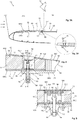
- an aircraft nacelle comprises, at the front, an air inlet 50 with a first duct 52 configured to channel a flow of air towards a second duct 54.
- a motor 56 disposed in the extension of the first conduit.
- the first duct 52 comprises at least one acoustic panel 60, generally several acoustic panels 60 juxtaposed on the circumference of the first duct 52.
- Each acoustic panel 60 comprises in the radial direction, away from the axis of the actuator, a layer acoustically resistive 62, at least one alveolar layer 64 and a reflective layer 66.
- Each acoustic panel 60 includes an inner surface 60Si in contact with the flow of air flowing in the first conduit 52 and an outer surface 60Se opposite the inner surface 60Si.
- the second duct 54 comprises at least one panel 68, generally several panels 68 juxtaposed on the circumference of the second duct 54.
- the panels 68 are acoustic panels which each comprise in the radial direction, away from the axis of the motorization, an acoustically resistive layer 70, at least one cellular layer 72 and a reflective layer 74 also called thereafter outer wall 74.
- Each panel 68 includes an inner surface 68Si in contact with the flow of air flowing in the second conduit 54 and an outer surface 68Se opposite the inner surface 68Si.
- Acoustic panels 62 are not more detailed because they are known to those skilled in the art. It is the same for the panels 68 of the second conduit 54 which are known under the name "Fan case" in English.
- the air inlet 50 and the motor 56 are connected by a link 76 which comprises a sleeve 78 secured to the second conduit 54, configured to receive an end of the first conduit 52 as well as connecting elements 80 which connect the sleeve 78 and the first conduit 52, which are distributed over the entire circumference of the nacelle and which comprise rods which are oriented radially.
- the sleeve 78 is integral with the first conduit 52, the second conduit 54 engages in the sleeve 78 and the connecting elements 80 connect the sleeve 78 and the second conduit 54.
- the sleeve 78 is made in one piece with the first or second conduit 52 or 54 or with at least one of the layers of the first or second conduit 52 or 54.
- the first duct 52 of the air inlet 50 and the second duct 54 of the motorization 56 are connected by only a series of connecting elements 80.
- the first duct 52, the second duct 54 and the sleeve 78 may be made of composite material insofar as the sleeve 78 is oriented longitudinally in the extension of one of the two conduits 52, 54.
- the outer wall 74 of each panel 68 extends forwardly of the nacelle relative to the rest of the panel 68.
- the outer walls 74 of the panels 68 form a sleeve 78 configured to receive the end 52E of the acoustic panels 60 of the first conduit 52.
- the sleeve 78 is spaced from the inner surface 68Si of each panel 68 by a distance greater than or equal to the height (distance measured in the radial direction) of the end 52E of the panels Acoustic 60 of the first conduit 52 so that the inner surfaces 68Si of the panels 68 of the second conduit 54 are in the extension of the inner surfaces 60Se of the acoustic panels 60 of the first conduit 52.
- Each connecting element 80 is a bolt which comprises on the one hand a screw 82 with a threaded rod 84 oriented in the radial direction and a head 86, and on the other hand, a nut 88 configured to allow screwing of the threaded rod 84.
- the nut 88 is connected to the sleeve 78 by a system for immobilizing in rotation said nut 88 around a radial axis of rotation, to allow screwing and tightening of the screw 82 without having need to immobilize in rotation the nut 88 with a tool.
- the nut 88 is connected directly to the outer surface of the sleeve 78, for example by riveting, crimping or the like.
- the nut 88 is a sleeve nut (of the "barrel nut” type) and is immobilized in rotation in a support 90 which is itself connected to the outer surface of the sleeve 78.
- the connecting elements 80 may each comprise a sleeve 91 deformable in compression positioned around the threaded rod 84.
- each connecting element 80 is embedded in the acoustically resistive layer 62 and / or the cellular layer 64 of the acoustic panels 60.
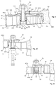
- the acoustically resistive layer 62 and the cellular layer 64 comprise a recess 92 configured to house the head 86.
- the reflective layer 66 comprises a through hole 94 with a lower section at the head 86 of the connecting element 80.
- the acoustic panel 60 comprises a recess 92 which passes through the panel 60 and which has substantially the same section over the entire height of the acoustic panel 60.
- the recesses 92 are disjoint and have a smallest possible section so as not to alter the acoustic treatment too much.
- each acoustic panel 60 comprises, for each recess 92, a plug 94 provided with a surface 94S flush with the inner surface 60Si of the acoustic panel 60 and connected by any suitable means to the panel acoustic 60.
- each cap 94 is connected to the acoustic panel 60 by gluing, riveting.
- each plug 94 is connected to the acoustic panel 60 by a support C 96 having a first flange 96.1 connected to the reflective layer 66 by screws or rivets 98 and a second flange 96.2 connected to the cap 94 by screws or rivets 100 .
- each recess 92 comprises a peripheral edge 102 with a section substantially equal to that of the head 86 of the connecting element 80.
- the head 86 of the element of link 80 comprises a surface 104 in the extension of the inner surface 60Si of the acoustic panel 60.
- an O-ring 106 is interposed between the connecting element 80 and the peripheral edge 102 of the recess 92.
- the plug 94 is a cap with a cylindrical side wall that fits into the recess 92.
- the first duct 52 is connected directly to the sleeve 78 by the connecting elements 80.
- the first duct 52 is connected to the sleeve 78 via at least one connecting blade 108 disposed between the first duct 52 and the sleeve 78.
- blade By blade is meant a part which has a thickness (dimension taken in the radial direction) significantly smaller than its width (dimension taken along the circumference) and / or its length (dimension taken in the longitudinal direction).
- connection 76 between the air inlet 50 and the motorization 56 comprises a plurality of connecting blades 108 which are distributed over the entire circumference of the first duct 52.
- the connecting strips 108 extend over identical angular sectors ⁇ to balance the forces.
- the link 76 comprises three connecting blades 108 which each extend over an angular sector of approximately 120 °.
- Each link blade 108 comprises at least a first junction zone 110 spaced from the first conduit 52 in the radial direction and configured to connect the connecting blade 108 and the sleeve 78 and at least a second junction zone 114, shifted in the direction longitudinal to the first junction zone 110, configured to connect the connecting blade 108 and the first conduit 52.
- Each first junction zone comprises a through hole 112 configured to house the threaded rod 84 of the connecting element 80.
- Each second junction zone 114 comprises at least one fastening element 116, for example a rivet, for connecting the connecting blade 108 and the first conduit 52.
- Each connecting blade 108 is configured to deform in operation elastically in the radial direction.
- the first junction zone 110 can move in the radial direction with respect to the second junction zone 114 when a force, oriented in the radial direction and not exceeding a given threshold, is exercised between the first and second conduits 52, 54.
- each connecting blade 108 comprises a third junction zone 118 which is connected to the first conduit 52 by at least one fastening element 120 (shown schematically by a center line), such as for example a rivet, the second and third zones junction 114 and 118 being disposed on either side of the first junction zone 110.
- each connecting blade 108 includes a rearwardly directed edge 122 of the nacelle which is free and not connected to the first conduit 52.
- the connecting blade 108 ensures only the connection 76 between the first conduit 52 and the sleeve 78.
- the connecting blade 108 comprises an extension 124 connected to a frame 126.
- the connecting blade 108 is not dedicated to the connection 76 between the first conduit 52 and the sleeve 78.
- the connecting blades 108 are fixed to the first conduit 52.
- the first conduit 52 provided with the connecting blades 108 is fitted into the sleeve 78.
- the edge 122 oriented to the second duct 54 is curved to promote the introduction of connecting strips 108 fixed to the first conduit 52.
- the screws 82 are placed and tightened from inside the first and second ducts 52 and 54.
- connection strips 108 deformingly limit the propagation of stresses between the first and second conduits 52, 54.
- the link 76 comprises a centralizer 130 connected to the duct 52 which promotes the centering of the first duct 52 with respect to the sleeve 78.
- the centralizer 130 comprises a plurality of elastic blades distributed over the periphery of the first duct 52.
Landscapes
- Engineering & Computer Science (AREA)
- Aviation & Aerospace Engineering (AREA)
- Chemical & Material Sciences (AREA)
- Combustion & Propulsion (AREA)
- Structures Of Non-Positive Displacement Pumps (AREA)
- Soundproofing, Sound Blocking, And Sound Damping (AREA)
Claims (11)
- Gondel eines Luftfahrzeugs, die einen mit einem Lufteinlass (50) verbundenen Kanal und einen mit einer Motorisierung (56) verbundenen Kanal aufweist, wobei der mit dem Lufteinlass (50) verbundene Kanal dazu eingerichtet ist, eine Luftströmung zu dem mit der Motorisierung (56) verbundenen Kanal zu kanalisieren, der in der Verlängerung des mit dem Lufteinlass (50) verbundenen Kanals angeordnet ist, und eine Verbindung (76) zwischen dem mit dem Lufteinlass (50) verbundenen Kanal und dem mit der Motorisierung (56) verbundenen Kanal aufweist, wobei die Verbindung (76) einen Stutzen (78) aufweist, in den ein Ende eines ersten Kanals (52) zwischen dem mit dem Lufteinlass (50) verbundenen Kanal und dem mit der Motorisierung (56) verbundenen Kanal eingesetzt ist, wobei der Stutzen (78) mit einem zweiten Kanal (54) verbunden ist, der zwischen dem mit dem Lufteinlass (50) verbundenen Kanal und dem mit der Motorisierung (56) verbundenen Kanal liegt, und wobei der Stutzen (78) in Längsrichtung entlang der Verlängerung eines der beiden Kanäle (52, 54) ausgerichtet ist, und die Verbindungselemente (80) aufweist, die den Stutzen (78) und den ersten Kanal (52) verbinden und die über den gesamten Umfang der Gondel verteilt sind, dadurch gekennzeichnet, dass jedes Verbindungselement (80) einerseits eine Schraube (82) mit einem in radiale Richtung ausgerichteten Gewindeschaft (84) und einen vom Inneren des ersten Kanals (52) zugänglichen Kopf (86) und andererseits eine Mutter (88) aufweist, die auf den Gewindeschaft (84) aufgeschraubt ist und die mit dem Stutzen (78) durch ein System verbunden ist, das eine Drehung der Mutter (88) um eine radiale Drehachse verhindert.
- Gondel eines Luftfahrzeugs nach Anspruch 1, dadurch gekennzeichnet, dass die Mutter (88) unmittelbar mit einer äußeren Oberfläche des Stutzens (78) verbunden ist.
- Gondel eines Luftfahrzeugs nach Anspruch 1, dadurch gekennzeichnet, dass die Mutter (88) eine Hülsenmutter ist, deren Drehung durch eine Halterung (90) verhindert ist, die mit einer äußeren Oberfläche des Stutzens (78) verbunden ist.
- Gondel eines Luftfahrzeugs nach einem der vorhergehenden Ansprüche, dadurch gekennzeichnet, dass der erste Kanal (52) wenigstens eine akustische Platte (60) aufweist, die in radiale Richtung mit zunehmendem Abstand von der Achse der Motorisierung (56) eine schalldämpfende Schicht (62), wenigstens eine kammerartige Schicht (64) und eine reflektierende Schicht (66) aufweist und dass für jedes Verbindungselement (80) wenigstens die schalldämpfende Schicht (62) und die kammerartige Schicht (64) eine Ausnehmung (92) aufweisen, die zur Aufnahme des Kopfs (86) des Verbindungselements (80) eingerichtet ist.
- Gondel eines Luftfahrzeugs nach Anspruch 4, dadurch gekennzeichnet, dass jede akustische Platte (60) für jede Ausnehmung (92) eine Abdeckung (94) aufweist, die mit der akustischen Platte (60) verbunden ist und mit einer Oberfläche (94S) versehen ist, die in der Verlängerung einer inneren Oberfläche (60Si) der akustischen Platte (60) angeordnet ist.
- Gondel eines Luftfahrzeugs nach Anspruch 4, dadurch gekennzeichnet, dass jede Ausnehmung (92) eine Umfangskante (102) aufweist, deren Querschnitt im Wesentlichen gleich dem Querschnitt des Kopfs (86) des Verbindungselements (80) ist, wobei der Kopf (86) des Verbindungselements (80) eine Oberfläche (104) aufweist, die in der Verlängerung einer inneren Oberfläche (60Si) der akustischen Platte (60) angeordnet ist und wobei ein O-Ring (106) zwischen das Verbindungselement (80) und die Umfangskante (102) der Ausnehmung (92) eingebracht ist.
- Gondel eines Luftfahrzeugs nach einem der vorhergehenden Ansprüche, dadurch gekennzeichnet, dass die Verbindung (76) wenigstens einen Verbindungsstreifen (108) aufweist, der dazu eingerichtet ist, den ersten Kanal (52) und den Stutzen (78) zu verbinden und zwischen dem ersten Kanal (52) und dem Stutzen (78) angeordnet ist, wobei jeder Verbindungsstreifen (108) wenigstens einen ersten Verbindungsbereich (110) aufweist, der dazu eingerichtet ist, den Verbindungsstreifen (108) und den Stutzen (78) zu verbinden, und der in radiale Richtung vom ersten Kanal (52) entfernt ist, und wenigstens einen zweiten Verbindungsbereich (114) aufweist, der dazu eingerichtet ist, den Verbindungsstreifen (108) und den ersten Kanal (52) zu verbinden und der in longitudinale Richtung bezüglich des ersten Verbindungsbereichs (110) versetzt ist.
- Gondel eines Luftfahrzeugs nach dem vorhergehenden Anspruch, dadurch gekennzeichnet, dass jeder Verbindungsstreifen (108) dazu eingerichtet ist, sich beim Betrieb in radiale Richtung auf elastische Weise zu verformen.
- Gondel eines Luftfahrzeugs nach Anspruch 7 oder 8, dadurch gekennzeichnet, dass jeder Verbindungsstreifen (108) einen dritten Verbindungsbereich (118) aufweist, der dazu eingerichtet ist, den Verbindungsstreifen (108) und den ersten Kanal (52) zu verbinden, wobei der zweite und dritte Verbindungsbereich (114, 118) beiderseits des ersten Verbindungsbereichs (110) angeordnet sind.
- Gondel eines Luftfahrzeugs nach Anspruch 7 oder 8, dadurch gekennzeichnet, dass die zweiten Verbindungsbereiche (114) bezüglich der ersten Verbindungsbereiche (110) im vorderen Bereich der Gondel angeordnet sind und dass jeder Verbindungsstreifen (108) einen Rand (122) aufweist, der dem hinteren Bereich der Gondel zugewandt ist und frei ist.
- Gondel eines Luftfahrzeugs nach einem der Ansprüche 7 bis 10, dadurch gekennzeichnet, dass jeder Verbindungsstreifen (108) einen dem zweiten Kanal (54) zugewandten gekrümmten Rand aufweist.
Applications Claiming Priority (1)
| Application Number | Priority Date | Filing Date | Title |
|---|---|---|---|
| FR1659899A FR3057545A1 (fr) | 2016-10-13 | 2016-10-13 | Nacelle d'aeronef comprenant une liaison entre un conduit d'une entree d'air et un conduit d'une motorisation |
Publications (2)
| Publication Number | Publication Date |
|---|---|
| EP3309078A1 EP3309078A1 (de) | 2018-04-18 |
| EP3309078B1 true EP3309078B1 (de) | 2019-06-05 |
Family
ID=58162714
Family Applications (1)
| Application Number | Title | Priority Date | Filing Date |
|---|---|---|---|
| EP17194690.8A Active EP3309078B1 (de) | 2016-10-13 | 2017-10-04 | Luftfahrzeuggondel, die eine verbindung zwischen einer luftleitung und einer motorisierungsleitung umfasst |
Country Status (3)
| Country | Link |
|---|---|
| EP (1) | EP3309078B1 (de) |
| CN (1) | CN107985612B (de) |
| FR (1) | FR3057545A1 (de) |
Families Citing this family (2)
| Publication number | Priority date | Publication date | Assignee | Title |
|---|---|---|---|---|
| FR3128444A1 (fr) | 2021-10-26 | 2023-04-28 | Airbus Operations (S.A.S.) | Nacelle d’aéronef comprenant une liaison entre des conduits comportant des collerettes orientées vers l’intérieur et aéronef comprenant au moins une telle nacelle |
| FR3142454B1 (fr) * | 2022-11-28 | 2024-10-18 | Safran Nacelles | Entree d’air de nacelle de turboreacteur a montage ameliore |
Family Cites Families (5)
| Publication number | Priority date | Publication date | Assignee | Title |
|---|---|---|---|---|
| FR2498793A1 (fr) * | 1981-01-29 | 1982-07-30 | Snecma | Garniture insonorisante pour conduit de gaz notamment pour veine de soufflante de turboreacteur et outillage pour sa fabrication |
| FR2926791B1 (fr) * | 2008-01-29 | 2010-05-28 | Aircelle Sa | Entree d'air pour nacelle d'aeronef, et ensemble propulsif comprenant une telle entree d'air |
| FR2926789B1 (fr) * | 2008-01-29 | 2010-05-28 | Aircelle Sa | Nacelle pour turboreacteur |
| US8197191B2 (en) * | 2009-04-14 | 2012-06-12 | Rohr, Inc. | Inlet section of an aircraft engine nacelle |
| FR2954282B1 (fr) * | 2009-12-22 | 2012-02-17 | Airbus Operations Sas | Nacelle incorporant un element de jonction entre une levre et un panneau d'attenuation acoustique |
-
2016
- 2016-10-13 FR FR1659899A patent/FR3057545A1/fr not_active Withdrawn
-
2017
- 2017-10-04 EP EP17194690.8A patent/EP3309078B1/de active Active
- 2017-10-10 CN CN201710936530.0A patent/CN107985612B/zh active Active
Non-Patent Citations (1)
| Title |
|---|
| None * |
Also Published As
| Publication number | Publication date |
|---|---|
| CN107985612B (zh) | 2022-10-18 |
| EP3309078A1 (de) | 2018-04-18 |
| CN107985612A (zh) | 2018-05-04 |
| FR3057545A1 (fr) | 2018-04-20 |
Similar Documents
| Publication | Publication Date | Title |
|---|---|---|
| EP2516271B1 (de) | Triebwerksgondel mit einem element zur verbindung einer umkantung mit einer schalldämmungsplatte | |
| EP2554822B1 (de) | Speziell angepasste Verbindungsvorrichtung zur Sicherstellung der Verbindung zwischen einem Lufteinlass und der Motorisierung einer Luftfahrzeuggondel | |
| EP2318679B1 (de) | Gondel einer turbomaschine | |
| EP3309075B1 (de) | Luftfahrzeuggondel, die eine verbindung zwischen einem lufteinlass und einer motorisierung umfasst | |
| FR2936223A1 (fr) | Dispositif de liaison entre une entree d'air et une motorisation d'une nacelle d'aeronef | |
| FR3005100A1 (fr) | Carter de turbomachine | |
| US11325717B2 (en) | Aircraft nacelle including a link between a conduit of an air inlet and a conduit of an engine | |
| FR2954281A1 (fr) | Panneau pour le traitement acoustique a epaisseur evolutive | |
| EP2554480B1 (de) | Speziell angepasste Verbindungsvorrichtung zur Sicherstellung der Verbindung zwischen einem Lufteinlass und der Motorisierung einer Luftfahrzeuggondel | |
| EP3309078B1 (de) | Luftfahrzeuggondel, die eine verbindung zwischen einer luftleitung und einer motorisierungsleitung umfasst | |
| FR2998547A1 (fr) | Nacelle d'aeronef comprenant une liaison deformable entre une entree d'air et une motorisation | |
| FR2998545A1 (fr) | Nacelle d'aeronef comprenant une liaison renforcee entre une entree d'air et une motorisation | |
| EP2554481B1 (de) | Speziell angepasste Verbindungsvorrichtung zur Sicherstellung der Verbindung zwischen einem Lufteinlass und der Motorisierung einer Luftfahrzeuggondel | |
| FR2966125A1 (fr) | Ensemble d'accrochage d'une suspension d'un ensemble propulsif d'aeronef | |
| EP2441676B1 (de) | Luftfahrzeuggondel, die eine fortlaufende Verbindungszone zwischen einer Außenwand und einem Vorderrahmen umfasst und Herstellungsverfahren | |
| FR3055885A1 (fr) | Nacelle d'aeronef comprenant une liaison entre une entree d'air et une motorisation qui comporte une bride | |
| EP4173961B1 (de) | Flugzeuggondel mit einer verbindung zwischen durchgängen mit nach innen gerichteten flanschen und flugzeug mit mindestens einer solchen gondel | |
| FR2922588A1 (fr) | Disque ou tambour de rotor d'une turbomachine | |
| EP2554479B1 (de) | Speziell angepasste Verbindungsvorrichtung zur Sicherstellung der Verbindung zwischen einem Lufteinlass und der Motorisierung einer Luftfahrzeuggondel | |
| EP3653268A1 (de) | Brandschutzwand, die eine anschlussvorrichtung einer kanalisation sowie ein wärmeschutzschild umfasst, und luftfahrzeug, das mindestens eine solche brandschutzwand umfasst | |
| EP4375192B1 (de) | Flugzeug mit mindestens einer zur begrenzung des auftretens von aerodynamischem geräusch konfigurierten lufteinlassvorrichtung | |
| FR3101855A1 (fr) | Dispositif d’évacuation de fluide pour aéronef, ensemble propulseur d’aéronef comprenant un tel dispositif d’évacuation de fluide et aéronef comprenant au moins un tel dispositif d’évacuation de fluide | |
| FR3111332A1 (fr) | Mât d’aéronef comportant au moins un joint d’étanchéité intercalé entre une structure fixe et un panneau démontable d’un carénage | |
| EP4613645A1 (de) | Flugzeug-lufteinlass mit einer lippe, einem innenkanal sowie mindestens einer radialen versteifung, die mit dem innenkanal verbunden und von der lippe beabstandet ist | |
| WO2026033184A1 (fr) | Systeme d'etancheite pour ensemble propulsif d'aeronef |
Legal Events
| Date | Code | Title | Description |
|---|---|---|---|
| PUAI | Public reference made under article 153(3) epc to a published international application that has entered the european phase |
Free format text: ORIGINAL CODE: 0009012 |
|
| STAA | Information on the status of an ep patent application or granted ep patent |
Free format text: STATUS: THE APPLICATION HAS BEEN PUBLISHED |
|
| AK | Designated contracting states |
Kind code of ref document: A1 Designated state(s): AL AT BE BG CH CY CZ DE DK EE ES FI FR GB GR HR HU IE IS IT LI LT LU LV MC MK MT NL NO PL PT RO RS SE SI SK SM TR |
|
| AX | Request for extension of the european patent |
Extension state: BA ME |
|
| STAA | Information on the status of an ep patent application or granted ep patent |
Free format text: STATUS: REQUEST FOR EXAMINATION WAS MADE |
|
| 17P | Request for examination filed |
Effective date: 20181008 |
|
| RBV | Designated contracting states (corrected) |
Designated state(s): AL AT BE BG CH CY CZ DE DK EE ES FI FR GB GR HR HU IE IS IT LI LT LU LV MC MK MT NL NO PL PT RO RS SE SI SK SM TR |
|
| RIC1 | Information provided on ipc code assigned before grant |
Ipc: B64D 33/02 20060101AFI20190123BHEP |
|
| GRAP | Despatch of communication of intention to grant a patent |
Free format text: ORIGINAL CODE: EPIDOSNIGR1 |
|
| STAA | Information on the status of an ep patent application or granted ep patent |
Free format text: STATUS: GRANT OF PATENT IS INTENDED |
|
| INTG | Intention to grant announced |
Effective date: 20190305 |
|
| GRAS | Grant fee paid |
Free format text: ORIGINAL CODE: EPIDOSNIGR3 |
|
| GRAA | (expected) grant |
Free format text: ORIGINAL CODE: 0009210 |
|
| STAA | Information on the status of an ep patent application or granted ep patent |
Free format text: STATUS: THE PATENT HAS BEEN GRANTED |
|
| AK | Designated contracting states |
Kind code of ref document: B1 Designated state(s): AL AT BE BG CH CY CZ DE DK EE ES FI FR GB GR HR HU IE IS IT LI LT LU LV MC MK MT NL NO PL PT RO RS SE SI SK SM TR |
|
| REG | Reference to a national code |
Ref country code: GB Ref legal event code: FG4D Free format text: NOT ENGLISH |
|
| REG | Reference to a national code |
Ref country code: CH Ref legal event code: EP |
|
| REG | Reference to a national code |
Ref country code: AT Ref legal event code: REF Ref document number: 1139753 Country of ref document: AT Kind code of ref document: T Effective date: 20190615 |
|
| REG | Reference to a national code |
Ref country code: IE Ref legal event code: FG4D Free format text: LANGUAGE OF EP DOCUMENT: FRENCH |
|
| REG | Reference to a national code |
Ref country code: DE Ref legal event code: R096 Ref document number: 602017004309 Country of ref document: DE |
|
| REG | Reference to a national code |
Ref country code: NL Ref legal event code: MP Effective date: 20190605 |
|
| REG | Reference to a national code |
Ref country code: LT Ref legal event code: MG4D |
|
| PG25 | Lapsed in a contracting state [announced via postgrant information from national office to epo] |
Ref country code: HR Free format text: LAPSE BECAUSE OF FAILURE TO SUBMIT A TRANSLATION OF THE DESCRIPTION OR TO PAY THE FEE WITHIN THE PRESCRIBED TIME-LIMIT Effective date: 20190605 Ref country code: LT Free format text: LAPSE BECAUSE OF FAILURE TO SUBMIT A TRANSLATION OF THE DESCRIPTION OR TO PAY THE FEE WITHIN THE PRESCRIBED TIME-LIMIT Effective date: 20190605 Ref country code: FI Free format text: LAPSE BECAUSE OF FAILURE TO SUBMIT A TRANSLATION OF THE DESCRIPTION OR TO PAY THE FEE WITHIN THE PRESCRIBED TIME-LIMIT Effective date: 20190605 Ref country code: ES Free format text: LAPSE BECAUSE OF FAILURE TO SUBMIT A TRANSLATION OF THE DESCRIPTION OR TO PAY THE FEE WITHIN THE PRESCRIBED TIME-LIMIT Effective date: 20190605 Ref country code: NO Free format text: LAPSE BECAUSE OF FAILURE TO SUBMIT A TRANSLATION OF THE DESCRIPTION OR TO PAY THE FEE WITHIN THE PRESCRIBED TIME-LIMIT Effective date: 20190905 Ref country code: AL Free format text: LAPSE BECAUSE OF FAILURE TO SUBMIT A TRANSLATION OF THE DESCRIPTION OR TO PAY THE FEE WITHIN THE PRESCRIBED TIME-LIMIT Effective date: 20190605 Ref country code: SE Free format text: LAPSE BECAUSE OF FAILURE TO SUBMIT A TRANSLATION OF THE DESCRIPTION OR TO PAY THE FEE WITHIN THE PRESCRIBED TIME-LIMIT Effective date: 20190605 |
|
| PG25 | Lapsed in a contracting state [announced via postgrant information from national office to epo] |
Ref country code: BG Free format text: LAPSE BECAUSE OF FAILURE TO SUBMIT A TRANSLATION OF THE DESCRIPTION OR TO PAY THE FEE WITHIN THE PRESCRIBED TIME-LIMIT Effective date: 20190905 Ref country code: GR Free format text: LAPSE BECAUSE OF FAILURE TO SUBMIT A TRANSLATION OF THE DESCRIPTION OR TO PAY THE FEE WITHIN THE PRESCRIBED TIME-LIMIT Effective date: 20190906 Ref country code: RS Free format text: LAPSE BECAUSE OF FAILURE TO SUBMIT A TRANSLATION OF THE DESCRIPTION OR TO PAY THE FEE WITHIN THE PRESCRIBED TIME-LIMIT Effective date: 20190605 Ref country code: LV Free format text: LAPSE BECAUSE OF FAILURE TO SUBMIT A TRANSLATION OF THE DESCRIPTION OR TO PAY THE FEE WITHIN THE PRESCRIBED TIME-LIMIT Effective date: 20190605 |
|
| REG | Reference to a national code |
Ref country code: AT Ref legal event code: MK05 Ref document number: 1139753 Country of ref document: AT Kind code of ref document: T Effective date: 20190605 |
|
| PG25 | Lapsed in a contracting state [announced via postgrant information from national office to epo] |
Ref country code: EE Free format text: LAPSE BECAUSE OF FAILURE TO SUBMIT A TRANSLATION OF THE DESCRIPTION OR TO PAY THE FEE WITHIN THE PRESCRIBED TIME-LIMIT Effective date: 20190605 Ref country code: AT Free format text: LAPSE BECAUSE OF FAILURE TO SUBMIT A TRANSLATION OF THE DESCRIPTION OR TO PAY THE FEE WITHIN THE PRESCRIBED TIME-LIMIT Effective date: 20190605 Ref country code: SK Free format text: LAPSE BECAUSE OF FAILURE TO SUBMIT A TRANSLATION OF THE DESCRIPTION OR TO PAY THE FEE WITHIN THE PRESCRIBED TIME-LIMIT Effective date: 20190605 Ref country code: PT Free format text: LAPSE BECAUSE OF FAILURE TO SUBMIT A TRANSLATION OF THE DESCRIPTION OR TO PAY THE FEE WITHIN THE PRESCRIBED TIME-LIMIT Effective date: 20191007 Ref country code: RO Free format text: LAPSE BECAUSE OF FAILURE TO SUBMIT A TRANSLATION OF THE DESCRIPTION OR TO PAY THE FEE WITHIN THE PRESCRIBED TIME-LIMIT Effective date: 20190605 Ref country code: NL Free format text: LAPSE BECAUSE OF FAILURE TO SUBMIT A TRANSLATION OF THE DESCRIPTION OR TO PAY THE FEE WITHIN THE PRESCRIBED TIME-LIMIT Effective date: 20190605 Ref country code: CZ Free format text: LAPSE BECAUSE OF FAILURE TO SUBMIT A TRANSLATION OF THE DESCRIPTION OR TO PAY THE FEE WITHIN THE PRESCRIBED TIME-LIMIT Effective date: 20190605 |
|
| PG25 | Lapsed in a contracting state [announced via postgrant information from national office to epo] |
Ref country code: SM Free format text: LAPSE BECAUSE OF FAILURE TO SUBMIT A TRANSLATION OF THE DESCRIPTION OR TO PAY THE FEE WITHIN THE PRESCRIBED TIME-LIMIT Effective date: 20190605 Ref country code: IS Free format text: LAPSE BECAUSE OF FAILURE TO SUBMIT A TRANSLATION OF THE DESCRIPTION OR TO PAY THE FEE WITHIN THE PRESCRIBED TIME-LIMIT Effective date: 20191005 Ref country code: IT Free format text: LAPSE BECAUSE OF FAILURE TO SUBMIT A TRANSLATION OF THE DESCRIPTION OR TO PAY THE FEE WITHIN THE PRESCRIBED TIME-LIMIT Effective date: 20190605 |
|
| REG | Reference to a national code |
Ref country code: DE Ref legal event code: R097 Ref document number: 602017004309 Country of ref document: DE |
|
| PG25 | Lapsed in a contracting state [announced via postgrant information from national office to epo] |
Ref country code: TR Free format text: LAPSE BECAUSE OF FAILURE TO SUBMIT A TRANSLATION OF THE DESCRIPTION OR TO PAY THE FEE WITHIN THE PRESCRIBED TIME-LIMIT Effective date: 20190605 |
|
| PLBE | No opposition filed within time limit |
Free format text: ORIGINAL CODE: 0009261 |
|
| STAA | Information on the status of an ep patent application or granted ep patent |
Free format text: STATUS: NO OPPOSITION FILED WITHIN TIME LIMIT |
|
| PG25 | Lapsed in a contracting state [announced via postgrant information from national office to epo] |
Ref country code: DK Free format text: LAPSE BECAUSE OF FAILURE TO SUBMIT A TRANSLATION OF THE DESCRIPTION OR TO PAY THE FEE WITHIN THE PRESCRIBED TIME-LIMIT Effective date: 20190605 Ref country code: PL Free format text: LAPSE BECAUSE OF FAILURE TO SUBMIT A TRANSLATION OF THE DESCRIPTION OR TO PAY THE FEE WITHIN THE PRESCRIBED TIME-LIMIT Effective date: 20190605 |
|
| 26N | No opposition filed |
Effective date: 20200306 |
|
| PG25 | Lapsed in a contracting state [announced via postgrant information from national office to epo] |
Ref country code: SI Free format text: LAPSE BECAUSE OF FAILURE TO SUBMIT A TRANSLATION OF THE DESCRIPTION OR TO PAY THE FEE WITHIN THE PRESCRIBED TIME-LIMIT Effective date: 20190605 Ref country code: MC Free format text: LAPSE BECAUSE OF FAILURE TO SUBMIT A TRANSLATION OF THE DESCRIPTION OR TO PAY THE FEE WITHIN THE PRESCRIBED TIME-LIMIT Effective date: 20190605 |
|
| PG25 | Lapsed in a contracting state [announced via postgrant information from national office to epo] |
Ref country code: LU Free format text: LAPSE BECAUSE OF NON-PAYMENT OF DUE FEES Effective date: 20191004 |
|
| REG | Reference to a national code |
Ref country code: BE Ref legal event code: MM Effective date: 20191031 |
|
| PG25 | Lapsed in a contracting state [announced via postgrant information from national office to epo] |
Ref country code: BE Free format text: LAPSE BECAUSE OF NON-PAYMENT OF DUE FEES Effective date: 20191031 |
|
| PG25 | Lapsed in a contracting state [announced via postgrant information from national office to epo] |
Ref country code: IE Free format text: LAPSE BECAUSE OF NON-PAYMENT OF DUE FEES Effective date: 20191004 |
|
| PG25 | Lapsed in a contracting state [announced via postgrant information from national office to epo] |
Ref country code: CY Free format text: LAPSE BECAUSE OF FAILURE TO SUBMIT A TRANSLATION OF THE DESCRIPTION OR TO PAY THE FEE WITHIN THE PRESCRIBED TIME-LIMIT Effective date: 20190605 |
|
| REG | Reference to a national code |
Ref country code: CH Ref legal event code: PL |
|
| PG25 | Lapsed in a contracting state [announced via postgrant information from national office to epo] |
Ref country code: LI Free format text: LAPSE BECAUSE OF FAILURE TO SUBMIT A TRANSLATION OF THE DESCRIPTION OR TO PAY THE FEE WITHIN THE PRESCRIBED TIME-LIMIT Effective date: 20201031 Ref country code: CH Free format text: LAPSE BECAUSE OF FAILURE TO SUBMIT A TRANSLATION OF THE DESCRIPTION OR TO PAY THE FEE WITHIN THE PRESCRIBED TIME-LIMIT Effective date: 20201031 |
|
| PG25 | Lapsed in a contracting state [announced via postgrant information from national office to epo] |
Ref country code: MT Free format text: LAPSE BECAUSE OF FAILURE TO SUBMIT A TRANSLATION OF THE DESCRIPTION OR TO PAY THE FEE WITHIN THE PRESCRIBED TIME-LIMIT Effective date: 20190605 Ref country code: HU Free format text: LAPSE BECAUSE OF FAILURE TO SUBMIT A TRANSLATION OF THE DESCRIPTION OR TO PAY THE FEE WITHIN THE PRESCRIBED TIME-LIMIT; INVALID AB INITIO Effective date: 20171004 |
|
| PG25 | Lapsed in a contracting state [announced via postgrant information from national office to epo] |
Ref country code: MK Free format text: LAPSE BECAUSE OF FAILURE TO SUBMIT A TRANSLATION OF THE DESCRIPTION OR TO PAY THE FEE WITHIN THE PRESCRIBED TIME-LIMIT Effective date: 20190605 |
|
| PGFP | Annual fee paid to national office [announced via postgrant information from national office to epo] |
Ref country code: DE Payment date: 20231020 Year of fee payment: 7 |
|
| REG | Reference to a national code |
Ref country code: DE Ref legal event code: R119 Ref document number: 602017004309 Country of ref document: DE |
|
| PG25 | Lapsed in a contracting state [announced via postgrant information from national office to epo] |
Ref country code: DE Free format text: LAPSE BECAUSE OF NON-PAYMENT OF DUE FEES Effective date: 20250501 |
|
| PGFP | Annual fee paid to national office [announced via postgrant information from national office to epo] |
Ref country code: GB Payment date: 20251024 Year of fee payment: 9 |
|
| PGFP | Annual fee paid to national office [announced via postgrant information from national office to epo] |
Ref country code: FR Payment date: 20251030 Year of fee payment: 9 |