EP3309108B1 - Trottoir roulant et procédé de fonctionnement d'un trottoir roulant - Google Patents
Trottoir roulant et procédé de fonctionnement d'un trottoir roulant Download PDFInfo
- Publication number
- EP3309108B1 EP3309108B1 EP16193910.3A EP16193910A EP3309108B1 EP 3309108 B1 EP3309108 B1 EP 3309108B1 EP 16193910 A EP16193910 A EP 16193910A EP 3309108 B1 EP3309108 B1 EP 3309108B1
- Authority
- EP
- European Patent Office
- Prior art keywords
- handrail
- people conveyor
- human body
- sensor
- touching
- Prior art date
- Legal status (The legal status is an assumption and is not a legal conclusion. Google has not performed a legal analysis and makes no representation as to the accuracy of the status listed.)
- Active
Links
Images


Classifications
-
- B—PERFORMING OPERATIONS; TRANSPORTING
- B66—HOISTING; LIFTING; HAULING
- B66B—ELEVATORS; ESCALATORS OR MOVING WALKWAYS
- B66B29/00—Safety devices of escalators or moving walkways
- B66B29/005—Applications of security monitors
-
- B—PERFORMING OPERATIONS; TRANSPORTING
- B66—HOISTING; LIFTING; HAULING
- B66B—ELEVATORS; ESCALATORS OR MOVING WALKWAYS
- B66B29/00—Safety devices of escalators or moving walkways
- B66B29/02—Safety devices of escalators or moving walkways responsive to, or preventing, jamming by foreign objects
- B66B29/04—Safety devices of escalators or moving walkways responsive to, or preventing, jamming by foreign objects for balustrades or handrails
-
- B—PERFORMING OPERATIONS; TRANSPORTING
- B66—HOISTING; LIFTING; HAULING
- B66B—ELEVATORS; ESCALATORS OR MOVING WALKWAYS
- B66B21/00—Kinds or types of escalators or moving walkways
- B66B21/02—Escalators
-
- B—PERFORMING OPERATIONS; TRANSPORTING
- B66—HOISTING; LIFTING; HAULING
- B66B—ELEVATORS; ESCALATORS OR MOVING WALKWAYS
- B66B23/00—Component parts of escalators or moving walkways
- B66B23/08—Carrying surfaces
- B66B23/12—Steps
Definitions
- the invention relates to a people conveyor with a moving handrail and a sensor which is configured for preventing parts of the human body from being jammed or squeezed between the moving handrail and a stationary handrail exit/entry portion.
- the invention also relates to a method of operating such a people conveyor.
- a people conveyor such as an escalator or a moving walkway is usually provided with balustrades extending on both sides along a longitudinal (conveying) direction of the people conveyor.
- a moving handrail in the form of a belt usually circulates in a closed loop around each balustrade.
- the handrail exit/entry portion is provided with a mechanical safety switch which stops the movement of the handrail (and usually the movement of the whole people conveyor) when activated.
- EP 0 420 061 A2 discloses an escalator handrail obstruction device with sensors.
- the device comprises an elastomeric collar which is positioned at the mouth of the escalator handrail reentry housing.
- the collar will deform when subjected to forces running parallel to the direction of travel of the handrail. Sufficient deformation of the collar will activate a switch which turns the escalator off. If an object enters the reentry housing and becomes lodged therein against the handrail, the forces generated thereby normal to the direction of travel of the handrail will activate a pressure sensor which in turn will turn the escalator off.
- a moving handrail of an escalator is monitored by a sensor at the end side of the pedestal near the opening.
- the sensor registers the presence of a hand or other object, which could be trapped by the moving handrail.
- the sensor without contact, registers variations in an electrical and/or magnetic field and can be fitted with a transmitting electrode and a receiver electrode.
- US 5 001 459 A discloses an escalator handrail guard warning device.
- the location on an escalator where the handrail reenters the balustrade is provided with an electrical field projector which will establish a limited extent electrical field around the handrail reentry housing.
- the field is established with a pair of antennae disposed adjacent to the handrail reentry.
- the antennae are preferably connected to the main AC power source for the escalator, and can be angularly adjusted to focus the field that they project.
- Shrouds are positioned adjacent to each antenna to confine the lateral extent of the field. An object entering the field will cause a field disturbance which creates a signal setting off an audible alarm. Subsequent stopping of the escalator can ensue if the disturbance is not removed in a predetermined amount of time.
- JP 2010 247 948 A discloses an inlet safety device with an inlet member for covering the outer periphery of a moving handrail in a position for making the moving handrail enter a skirt part and movably arranged in the moving direction of the moving handrail, and a plurality of detecting switches for detecting displacement in the moving direction of the moving handrail of the inlet member.
- the plurality of detecting switch parts detect the displacement of the inlet member in a different position of a displacement quantity of the inlet member.
- a people conveyor comprises two landing areas located at two opposing ends of the conveyor; a movable conveying element extending between the two landing areas and configured for conveying passengers between the two landing areas; a handrail, which extends parallel to the conveying element between the two landing areas and which is configured for moving with the conveying element; and handrail exit/entry portions.
- the handrail in particular may extend along a balustrade extending parallel to the conveying element between the two landing areas.
- At least one handrail exit/entry portion is provided at each of the landing areas, in particular at the bottom of the balustrade, and configured for emitting/receiving a return portion of the handrail.
- each handrail exit/entry portion may act as handrail exit portion or as handrail entry portion, respectively.
- a safety switch assembly is provided at a handrail exit/entry portion and configured for stopping the handrail when activated.
- the people conveyor is configured for being operated in only one conveyance direction, it might be sufficient to provide a safety switch assembly on only one end of the people conveyor, i.e. the end comprising the handrail entry portion receiving a return portion of the handrail.
- safety switch assemblies preferably should be provided at both ends of the people conveyor, as, depending on the actual conveying direction, both ends may act as handrail exit portion or as handrail entry portion, respectively.
- the safety switch assembly comprises at least one sensor surface providing a touch sensor for detecting any part of a human body, in particular a finger, approaching and/or touching at least one of the at least one sensor surfaces.
- the safety switch assembly further comprises a switching element which is configured for activating a safety switch when moved and which extends at least partially around the handrail exit/entry portion. Such a switching element results in a reliable activation of the switch.
- a switching element extending at least partially around the handrail exit/entry portion is reliably activated by parts of a human body touching the handrail in the vicinity of the handrail exit/entry portion.
- a method of operating a people conveyor comprises reducing the speed of the handrail element and/or issuing an optical and/or an acoustical alarm signal and/or reducing the speed of the handrail element in case the touch sensor detects any part of a human body, in particular a finger, approaching and/or touching at least one of the at least one sensor surfaces; and stopping any movement of the handrail in case the safety switch is activated.
- the operational security of the people conveyor is enhanced.
- the dangerous situation detected by the touch sensor may be resolved before the part of the human body is trapped. In consequence, stopping the handrail element or even the conveying element of the people conveyor, which is inconvenient for potential passengers and requires human interaction for restarting the operation of the people conveyor, may be avoided.
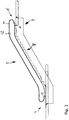
- Fig. 1 shows a schematic side view of a people conveyor 2, which in this case is provided in the form of an escalator. The skilled person, however, will easily understand that the invention may be applied similarly to a horizontal or inclined moving walkway.
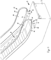
- Fig. 2 depicts a perspective view of a lower landing area 4 of the people conveyor 2
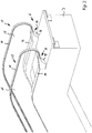
- Fig. 3 depicts a perspective view of an upper landing area 6 of the people conveyor 2.
- the people conveyor 2 comprises a truss 3 extending between the lower landing area 4 and the upper landing area 6.
- the truss 3 supports a movable conveying element 8, which in the case of an escalator is a step chain, and two balustrades 12 (only one of which is visible in Fig. 1 ) extending parallel to the conveying element 8 on both lateral sides of the conveying element 8.
- Each balustrade 12 comprises a lower base portion 14 and an upper portion 16, which is supported by the base potion 14.
- the upper portions 16 may be made of a transparent material, such as glass or acrylic glass, as shown in Figs. 2 and 3 .
- the upper portions 16 may be made of an intransparent material, such as metal, in particular steel, stainless steel or aluminum.
- the upper portions 16 of the balustrade 12 may extend vertically, as shown in Figs. 2 and 3 . This is typical for transparent balustrades.
- the upper portions 16 may be arranged at an angle with respect to the vertical direction, which is typical for balustrades made of an intransparent material such as metal.
- a moving handrail 10 which is provided in the form of a belt forming a closed loop, extends and circulates around each of the balustrades 12.
- Handrail exit/entry boxes 18 providing handrail exit/entry portions 19 are arranged at the ends of the lower base portions 14.
- Each of the handrail exit/entry boxes 18 comprises an opening (not visible in Figures 1 to 3 ) for receiving a lower return portion of the handrail 10. In operation, the handrail 10 will exit from or enter into the respective opening, depending on the conveying direction.
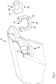
- Fig. 4 depicts an explosive perspective view of a handrail exit/entry box 18 according to an exemplary embodiment of the invention.
- Fig. 5 shows the same handrail exit/entry box 18 in an assembled state and
- Fig. 6 shows a sectional view thereof.
- the handrail exit/entry box 18 comprises an opening 20 for receiving a lower return portion of the handrail 10, which is not shown in Figures 4 to 6 .
- the opening 20 is partially surrounded by a movably mounted switching element 22, which in particular may be a rockable element.
- the switching element 22 supports a cap 24.
- the opening 20 In the assembled state, which is shown in Fig. 5 , the opening 20, an opening 23 formed within the switching element 22 (see Fig. 4 ) and an opening 25 formed within the cap 24 (see Fig. 4 ) are coaxially aligned.
- the handrail 10, which is not shown in Figures 4 to 6 extends trough said openings 20, 23, 25.
- a safety switch 30 (see Fig. 6 ), which in particular may be a mechanical safety switch and which is not visible in Figures 4 and 5 , is provided within the handrail exit/entry box 18.
- the safety switch 30, the switching element 22 and the cap 24 constitute a safety switch assembly 31.
- the safety switch 30 is configured to be activated by the switching element 22 when it is pushed towards the handrail exit/entry box 18, e.g. by a finger residing on the return portion of the handrail 10 (not shown) entering into the coaxially aligned openings 20, 23, 25.
- the safety switch 30 is activated.
- any movement of the handrail 12 is stopped in order to avoid that the part of the human body touching the cap 24 and/or the switching element 22 is pulled into the opening 25 and squeezed between the rim of the opening 25 and the handrail 12, which may result in severe injuries.
- At least one of the outer surfaces 26, 28 of the cap 24 and/or of the switching element 22 is configured as a sensor surface 27, 29 for providing, in combination with a corresponding detection circuit 32, a touch sensor, which allows to detect a part of a human body touching or approaching the at least one of the outer surfaces 26, 28 of the cap 24 and/or of the switching element 22.
- the touch sensor may be a capacitive sensor which is configured for detecting a change of capacity caused by the part of the human body approaching or touching the at least one of the outer surfaces 26, 28.
- the touch sensor may be an electrical sensor, which is configured for detecting a (small) electrical current flowing through a human body touching the at least one of the outer surfaces 26, 28.
- the outer surfaces 26, 28 of the cap 24 and/or the switching element 22 may be covered with an appropriate metallic or non-metallic, but electrically conductive, coating.
- the touch sensor may be an optical sensor comprising at least one optical sensor element which reacts on shading at least one of the outer surfaces 26, 28 by means of a part of a human body.
- a touch sensor allows to detect a severe risk that a part of a human body gets trapped and injured at a very early stage, in particular even before the switching element 22 is moved.
- the touch sensor allows to issue an alarm signal even before the switching element 22 is moved and the safety switch 30 is activated.
- an alarm signal may be issued in order to cause the human to remove his/her part of the body from the handrail exit/entry portion 19.
- the speed of the handrail 12, and optionally the speed of the conveying element 8 may be reduced for reducing the risk of pulling the detected part of the human body into the openings 20, 23, 25.
- the speed of the handrail 12 (and optionally the speed of the conveying element 8) may be increased back to normal speed without human intervention in order to return to normal operation.
- the safety switch may be a mechanical switch.
- a mechanical switch provides a reliable and inexpensive safety switch.
- the safety switch may be an optical switch, e.g. a switch comprising a light barrier which is blocked when the switch is activated.
- the sensor surface may be provided on an outer surface of the switching element in order to cause the touch sensor to be activated when the outer surface of the switching element is touched.
- the touch sensor may be provided as a capacitive sensor which is configured for detecting a change of capacity caused by an approaching portion of a human body.
- Capacitive sensors provide reliable and inexpensive touch sensors, which are able to detect parts of the human body approaching and/or touching the sensor surface.
- the touch sensor may be provided as an electrical sensor which is configured for detecting an electrical current flowing through a human body.
- Such electrical sensors provide reliable and inexpensive touch sensors, which are able to detect parts of the human body touching the sensor surface.
- the touch sensor may be provided as an optical sensor which is configured for optically detecting a portion of a human body approaching and/or touching the sensor surface.
- Optical sensors provide reliable and inexpensive touch sensors, which are able to detect parts of the human body approaching and/or touching the sensor surface.
- the people conveyor may be configured for issuing an optical alarm signal and/or an acoustic alarm signal in case the touch sensor detects a part of a human body approaching and/or touching the sensor surface.
- a method of operating a people conveyor may include issuing an optical and/or acoustical alarm signal in case the touch sensor detects any part of a human body, in particular a finger, approaching and/or touching the sensor surface.
- An optical alarm signal and/or an acoustic alarm signal may cause a human being to remove the detected part of his/her body from the entry portion before it is trapped or jammed within the opening. In case the part of the human body is removed in time, it may not be necessary to stop the movement of the handrail of the people conveyor. Thus, an inconvenient shutoff of the people conveyor may be avoided.
- the people conveyor may be configured for reducing the speed of the handrail in case the touch sensor detects a part of a human body approaching and/or touching the sensor surface.
- method of operating a people conveyor may include reducing the speed of the handrail element in case the touch sensor detects any part of a human body, in particular a finger, approaching and/or touching the sensor surface.
- Reducing the speed of the handrail may allow a human being to remove the detected part of his/her body from the entry portion before it is trapped or jammed within the opening. In case the part of the human body is removed in time, it may not be necessary to stop the movement of the handrail of the people conveyor. Thus, an inconvenient shutoff of the people conveyor may be avoided.
- the people conveyor may be configured for reducing the speed of the conveying element together with the handrail in order to avoid a speed difference between the conveying element and the handrail.
- the people conveyor may be configured for increasing the speed of the handrail, and of the conveying element if applicable, back to normal operational speed in case the touch sensor does no detect a part of a human body approaching and/or touching the sensor surface for at least a predetermined period of time. This allows the people conveyor to return to normal operation without human intervention.
- the people conveyor may be an escalator including a conveying element comprising a plurality of steps.
- the people conveyor may be a moving walkway including a conveying element comprising a plurality of pallets.
Landscapes
- Escalators And Moving Walkways (AREA)
Claims (12)
- Trottoir roulant (2) comprenant
deux zones d'atterrissage (4, 6) situées à deux extrémités opposées du trottoir roulant (2) ;
un élément de transport mobile (8) s'étendant entre les deux zones d'atterrissage (4, 6) et configuré pour transporter des passagers entre les deux zones d'atterrissage (4, 6) ;
une rampe (12) s'étendant parallèlement à l'élément de transport entre les deux zones d'atterrissage et configurée pour se déplacer avec l'élément de transport (8) ;
une partie d'entrée/de sortie de rampe (19) située dans l'une des zones d'atterrissage (4, 6) et configurée pour recevoir une partie retour de la rampe (12) ; et
un ensemble interrupteur de sécurité (31) prévu sur la partie d'entrée/de sortie de rampe (19) et configuré pour arrêter la rampe (12) lorsqu'il est activé ;
dans lequel l'ensemble interrupteur de sécurité (31) comprend :
au moins une surface de détection (27, 29) dotée d'un capteur tactile pour détecter une partie quelconque d'un corps humain, en particulier un doigt, approchant et/ou touchant au moins une des au moins une des surfaces de détection (27, 29), et
caractérisé en ce que l'ensemble interrupteur de sécurité (31) comprend en outre :
un élément de commutation (22) qui est configuré pour activer un interrupteur de sécurité (30) lorsqu'il est déplacé et qui s'étend au moins partiellement autour de la rampe (12). - Trottoir roulant (2) selon la revendication 1, dans lequel au moins une des au moins une des surfaces de détection (27, 29) est prévue sur une surface extérieure (28) de l'élément de commutation (22).
- Trottoir roulant (2) selon l'une quelconque des revendications précédentes, dans lequel le capteur tactile est prévu en tant que capteur capacitif qui est configuré pour détecter un changement de capacité provoqué par une partie approchante d'un corps humain.
- Trottoir roulant (2) selon l'une quelconque des revendications précédentes, dans lequel le capteur tactile est prévu en tant que capteur électrique qui est configuré pour détecter un courant électrique traversant un corps humain.
- Trottoir roulant (2) selon l'une quelconque des revendications précédentes, dans lequel le capteur tactile est prévu en tant que capteur optique qui est configuré pour détecter optiquement une partie d'un corps humain approchant et/ou touchant au moins une des au moins une des surfaces de détection (27, 29).
- Trottoir roulant (2) selon l'une quelconque des revendications précédentes, qui est configuré pour émettre un signal d'alarme optique et/ou un signal d'alarme acoustique si le capteur tactile détecte une partie d'un corps humain approchant et/ou touchant au moins une des au moins une des surfaces de détection (27, 29).
- Trottoir roulant (2) selon l'une quelconque des revendications précédentes, qui est configuré pour réduire la vitesse de la rampe (12) si le capteur tactile détecte une partie d'un corps humain approchant et/ou touchant au moins une des au moins une des surfaces de détection (27, 29).
- Trottoir roulant (2) selon la revendication 7, qui est configuré pour réduire la vitesse de l'élément de transport (8) si le capteur tactile détecte une partie d'un corps humain approchant et/ou touchant au moins une des au moins une des surfaces de détection (27, 29).
- Trottoir roulant (2) selon la revendication 7 ou 8, qui est configuré pour augmenter la vitesse de la rampe (12) et/ou de l'élément de transport (8) à une vitesse de fonctionnement normal si le capteur tactile ne détecte aucune partie d'un corps humain approchant et/ou touchant l'au moins une surface de détection (27, 29) pendant au moins une période prédéterminée.
- Trottoir roulant (2) selon l'une quelconque des revendications 1 à 9, dans lequel le trottoir roulant (2) est un escalier roulant comportant un élément de transport (8) comprenant une pluralité de marches.
- Trottoir roulant (2) selon l'une quelconque des revendications 1 à 9, dans lequel le trottoir roulant (2) est un tapis roulant comportant un élément de transport (8) comprenant une pluralité de palettes.
- Procédé de fonctionnement d'un trottoir roulant (2) selon l'une quelconque des revendications précédentes, dans lequel le procédé comprend :la réduction de la vitesse de l'élément de rampe (12) et/ou l'émission d'un signal d'alarme optique et/ou acoustique si le capteur tactile détecte une partie quelconque d'un corps humain, en particulier un doigt, approchant et/ou touchant au moins une des au moins une des surfaces de détection (27, 29) ; etl'arrêt du mouvement de la rampe (12) si l'interrupteur de sécurité (30) est activé.
Priority Applications (3)
| Application Number | Priority Date | Filing Date | Title |
|---|---|---|---|
| EP16193910.3A EP3309108B1 (fr) | 2016-10-14 | 2016-10-14 | Trottoir roulant et procédé de fonctionnement d'un trottoir roulant |
| US15/782,082 US10053337B2 (en) | 2016-10-14 | 2017-10-12 | People conveyor and method of operating a people conveyor |
| CN201710956535.XA CN107954302B (zh) | 2016-10-14 | 2017-10-13 | 载人运送器和操作载人运送器的方法 |
Applications Claiming Priority (1)
| Application Number | Priority Date | Filing Date | Title |
|---|---|---|---|
| EP16193910.3A EP3309108B1 (fr) | 2016-10-14 | 2016-10-14 | Trottoir roulant et procédé de fonctionnement d'un trottoir roulant |
Publications (2)
| Publication Number | Publication Date |
|---|---|
| EP3309108A1 EP3309108A1 (fr) | 2018-04-18 |
| EP3309108B1 true EP3309108B1 (fr) | 2020-03-25 |
Family
ID=57136759
Family Applications (1)
| Application Number | Title | Priority Date | Filing Date |
|---|---|---|---|
| EP16193910.3A Active EP3309108B1 (fr) | 2016-10-14 | 2016-10-14 | Trottoir roulant et procédé de fonctionnement d'un trottoir roulant |
Country Status (3)
| Country | Link |
|---|---|
| US (1) | US10053337B2 (fr) |
| EP (1) | EP3309108B1 (fr) |
| CN (1) | CN107954302B (fr) |
Families Citing this family (1)
| Publication number | Priority date | Publication date | Assignee | Title |
|---|---|---|---|---|
| CN114873423A (zh) * | 2022-04-27 | 2022-08-09 | 重庆市特种设备检测研究院 | 一种扶梯扶手带入口处安全保护装置及保护系统 |
Family Cites Families (33)
| Publication number | Priority date | Publication date | Assignee | Title |
|---|---|---|---|---|
| DE2006542B2 (de) | 1970-02-13 | 1972-04-20 | Maschinenfabrik Augsburg Nürnberg AG, Zweigniederlassung Nürnberg, 8500 Nürnberg | Handlaufeinfuehrung bei fahrsteigen wie fahrtreppen o dgl |
| JPH01317987A (ja) | 1988-06-15 | 1989-12-22 | Mitsubishi Electric Corp | マンコンベアの乗客検出装置 |
| AU617081B2 (en) * | 1989-09-29 | 1991-11-14 | Otis Elevator Company | Escalator handrail obstruction device with sensors |
| US5001459A (en) * | 1990-05-23 | 1991-03-19 | Otis Elevator Company | Escalator handrail guard warning device |
| US5072820A (en) * | 1991-05-14 | 1991-12-17 | Otis Elevator Company | Escalator handrail stop device |
| US5092446A (en) * | 1991-06-13 | 1992-03-03 | Ecs Corporation | Handrail monitoring system |
| US5245315A (en) * | 1992-09-08 | 1993-09-14 | Otis Elevator Company | Fiber optic escalator handrail intrusion detector shield |
| AUPN605295A0 (en) * | 1995-10-18 | 1995-11-09 | Loderway Pty. Limited | Systems for the conveyance of standing passengers |
| US6267219B1 (en) * | 2000-08-11 | 2001-07-31 | Otis Elevator Company | Electronic safety system for escalators |
| US20030136635A1 (en) * | 2002-01-04 | 2003-07-24 | Richard Lauch | Handrail vertical load detector |
| JP4401138B2 (ja) * | 2003-10-10 | 2010-01-20 | 東芝エレベータ株式会社 | 乗客コンベア |
| ZA200409385B (en) | 2003-12-08 | 2005-09-28 | Inventio Ag | Equipment for monitoring the space in front of escalators and moving walkways by high-frequency sensors |
| US7404477B1 (en) * | 2004-02-26 | 2008-07-29 | Toennisson H Eugene | Proximity hand rail monitor for a moving walkway |
| US6971496B1 (en) * | 2004-07-09 | 2005-12-06 | Kone Corporation | Escalator braking with multiple deceleration rates |
| FI20050047A7 (fi) | 2005-01-14 | 2006-07-15 | Kone Corp | Liukukäytävä, -ramppi tai -porras |
| ES2285949B1 (es) * | 2006-12-29 | 2009-03-16 | Thyssenkrupp Norte, S.A. | Dispositivo de seguridad para pasamanos moviles. |
| DE202008003486U1 (de) * | 2008-03-12 | 2008-05-15 | Thyssenkrupp Fahrtreppen Gmbh | Sicherheitsvorrichtung für eine Fahrtreppe |
| US8205735B2 (en) * | 2008-06-17 | 2012-06-26 | Intel-Ge Care Innovations Llc | Monitoring handrails to reduce falls |
| JP2010247948A (ja) * | 2009-04-15 | 2010-11-04 | Toshiba Elevator Co Ltd | 乗客コンベアのインレット安全装置 |
| ES2420779T3 (es) | 2009-04-20 | 2013-08-26 | Otis Elevator Company | Control de seguridad de transportador |
| US8210705B2 (en) | 2009-06-16 | 2012-07-03 | Hok Product Design, Llc | Touch-sensitive lighted hand rail |
| BR112012014183A2 (pt) | 2009-12-18 | 2016-05-31 | Otis Elevator Co | sistema para detectar uma pessoa, e, métodos para detecção de um passageiro e de uma pessoa |
| DE102010017802A1 (de) | 2010-07-08 | 2012-01-12 | Thyssenkrupp Fahrtreppen Gmbh | Sicherheitsvorrichtung für Fahrtreppen oder Fahrsteige sowie Fahrtreppe oder Fahrsteig |
| FI125399B (fi) * | 2010-11-02 | 2015-09-30 | Kone Corp | Ohjausjärjestely henkilökuljettimen ohjaamiseksi |
| EP2468676A1 (fr) | 2010-12-22 | 2012-06-27 | Inventio AG | Dispositif de transport pour personnes et/ou objets |
| CN201914827U (zh) | 2010-12-30 | 2011-08-03 | 上海纳杰电气成套有限公司 | 一种新型的自动扶梯扶手 |
| CN103842280B (zh) * | 2011-09-15 | 2018-03-30 | 通力股份公司 | 乘客输送机 |
| EP2708485B1 (fr) * | 2012-09-18 | 2014-09-03 | Cedes AG | Capteur de démarrage avec surveillance de vestibule pour escaliers roulants ou trottoirs roulants |
| US9792796B1 (en) * | 2014-06-25 | 2017-10-17 | Amazon Technologies, Inc. | Monitoring safety compliance based on RFID signals |
| FI125862B (fi) * | 2015-01-28 | 2016-03-15 | Kone Corp | Sähköinen turvallisuuslaite sekä kuljetinjärjestelmä |
| US20160237690A1 (en) | 2015-02-17 | 2016-08-18 | Elwha Llc | Systems and methods for monitoring use of rail on a footpath |
| US9547975B2 (en) | 2015-02-17 | 2017-01-17 | Elwha Llc | Systems and methods for monitoring use of rail on a footpath |
| CN205527255U (zh) * | 2016-01-22 | 2016-08-31 | 浙江蒂尔森电梯有限公司 | 一种具有安全制动装置的自动扶梯 |
-
2016
- 2016-10-14 EP EP16193910.3A patent/EP3309108B1/fr active Active
-
2017
- 2017-10-12 US US15/782,082 patent/US10053337B2/en active Active
- 2017-10-13 CN CN201710956535.XA patent/CN107954302B/zh active Active
Non-Patent Citations (1)
| Title |
|---|
| None * |
Also Published As
| Publication number | Publication date |
|---|---|
| CN107954302B (zh) | 2021-05-04 |
| CN107954302A (zh) | 2018-04-24 |
| US20180105399A1 (en) | 2018-04-19 |
| US10053337B2 (en) | 2018-08-21 |
| EP3309108A1 (fr) | 2018-04-18 |
Similar Documents
| Publication | Publication Date | Title |
|---|---|---|
| CN107973207B (zh) | 人员运送机的扶手系统以及防止在人员运送机的扶手系统上受伤的方法 | |
| JP2010247948A (ja) | 乗客コンベアのインレット安全装置 | |
| WO2013037115A1 (fr) | Trottoir roulant | |
| JP4967672B2 (ja) | 乗客コンベアの安全装置 | |
| EP3341317B1 (fr) | Tapis roulant | |
| EP3309108B1 (fr) | Trottoir roulant et procédé de fonctionnement d'un trottoir roulant | |
| JP5679611B1 (ja) | 乗客コンベア | |
| US20190112162A1 (en) | Comb plate and people conveyor | |
| EP0801021A2 (fr) | Dispositif de sécurité pour un transporteur de passagers | |
| JP6939937B1 (ja) | 乗客転倒検知装置を具える乗客コンベア | |
| JP6079663B2 (ja) | 乗客コンベアの安全装置 | |
| KR101413717B1 (ko) | 에스컬레이터의 안전장치 | |
| EP3473578A1 (fr) | Balustrade pour dispositif de transport de personnes | |
| JP2012106848A (ja) | 乗客コンベア | |
| JP2016179876A (ja) | 乗客コンベア | |
| JPH01226692A (ja) | エスカレータ或いは動く歩道の安全装置 | |
| JP4835211B2 (ja) | 乗客コンベア | |
| EP3549897A1 (fr) | Système de sécurité de balustrade pour un tapis roulant | |
| JP2013047140A (ja) | 乗客コンベアの安全装置 | |
| JPS63143192A (ja) | エスカレ−タ或いは動く歩道の安全装置 | |
| JP2010208832A (ja) | 乗客コンベア | |
| JPS63300091A (ja) | エスカレ−タの安全装置 | |
| JPH0192193A (ja) | エスカレータの安全装置 | |
| JP2017114595A (ja) | 乗客コンベア | |
| JP2005082361A (ja) | 乗客コンべア安全装置 |
Legal Events
| Date | Code | Title | Description |
|---|---|---|---|
| PUAI | Public reference made under article 153(3) epc to a published international application that has entered the european phase |
Free format text: ORIGINAL CODE: 0009012 |
|
| STAA | Information on the status of an ep patent application or granted ep patent |
Free format text: STATUS: THE APPLICATION HAS BEEN PUBLISHED |
|
| AK | Designated contracting states |
Kind code of ref document: A1 Designated state(s): AL AT BE BG CH CY CZ DE DK EE ES FI FR GB GR HR HU IE IS IT LI LT LU LV MC MK MT NL NO PL PT RO RS SE SI SK SM TR |
|
| AX | Request for extension of the european patent |
Extension state: BA ME |
|
| STAA | Information on the status of an ep patent application or granted ep patent |
Free format text: STATUS: REQUEST FOR EXAMINATION WAS MADE |
|
| 17P | Request for examination filed |
Effective date: 20181009 |
|
| RBV | Designated contracting states (corrected) |
Designated state(s): AL AT BE BG CH CY CZ DE DK EE ES FI FR GB GR HR HU IE IS IT LI LT LU LV MC MK MT NL NO PL PT RO RS SE SI SK SM TR |
|
| GRAP | Despatch of communication of intention to grant a patent |
Free format text: ORIGINAL CODE: EPIDOSNIGR1 |
|
| STAA | Information on the status of an ep patent application or granted ep patent |
Free format text: STATUS: GRANT OF PATENT IS INTENDED |
|
| INTG | Intention to grant announced |
Effective date: 20191204 |
|
| GRAS | Grant fee paid |
Free format text: ORIGINAL CODE: EPIDOSNIGR3 |
|
| GRAA | (expected) grant |
Free format text: ORIGINAL CODE: 0009210 |
|
| STAA | Information on the status of an ep patent application or granted ep patent |
Free format text: STATUS: THE PATENT HAS BEEN GRANTED |
|
| AK | Designated contracting states |
Kind code of ref document: B1 Designated state(s): AL AT BE BG CH CY CZ DE DK EE ES FI FR GB GR HR HU IE IS IT LI LT LU LV MC MK MT NL NO PL PT RO RS SE SI SK SM TR |
|
| REG | Reference to a national code |
Ref country code: GB Ref legal event code: FG4D |
|
| REG | Reference to a national code |
Ref country code: DE Ref legal event code: R096 Ref document number: 602016032424 Country of ref document: DE |
|
| REG | Reference to a national code |
Ref country code: AT Ref legal event code: REF Ref document number: 1248344 Country of ref document: AT Kind code of ref document: T Effective date: 20200415 Ref country code: IE Ref legal event code: FG4D |
|
| PG25 | Lapsed in a contracting state [announced via postgrant information from national office to epo] |
Ref country code: FI Free format text: LAPSE BECAUSE OF FAILURE TO SUBMIT A TRANSLATION OF THE DESCRIPTION OR TO PAY THE FEE WITHIN THE PRESCRIBED TIME-LIMIT Effective date: 20200325 Ref country code: RS Free format text: LAPSE BECAUSE OF FAILURE TO SUBMIT A TRANSLATION OF THE DESCRIPTION OR TO PAY THE FEE WITHIN THE PRESCRIBED TIME-LIMIT Effective date: 20200325 Ref country code: NO Free format text: LAPSE BECAUSE OF FAILURE TO SUBMIT A TRANSLATION OF THE DESCRIPTION OR TO PAY THE FEE WITHIN THE PRESCRIBED TIME-LIMIT Effective date: 20200625 |
|
| PG25 | Lapsed in a contracting state [announced via postgrant information from national office to epo] |
Ref country code: BG Free format text: LAPSE BECAUSE OF FAILURE TO SUBMIT A TRANSLATION OF THE DESCRIPTION OR TO PAY THE FEE WITHIN THE PRESCRIBED TIME-LIMIT Effective date: 20200625 Ref country code: SE Free format text: LAPSE BECAUSE OF FAILURE TO SUBMIT A TRANSLATION OF THE DESCRIPTION OR TO PAY THE FEE WITHIN THE PRESCRIBED TIME-LIMIT Effective date: 20200325 Ref country code: LV Free format text: LAPSE BECAUSE OF FAILURE TO SUBMIT A TRANSLATION OF THE DESCRIPTION OR TO PAY THE FEE WITHIN THE PRESCRIBED TIME-LIMIT Effective date: 20200325 Ref country code: GR Free format text: LAPSE BECAUSE OF FAILURE TO SUBMIT A TRANSLATION OF THE DESCRIPTION OR TO PAY THE FEE WITHIN THE PRESCRIBED TIME-LIMIT Effective date: 20200626 Ref country code: HR Free format text: LAPSE BECAUSE OF FAILURE TO SUBMIT A TRANSLATION OF THE DESCRIPTION OR TO PAY THE FEE WITHIN THE PRESCRIBED TIME-LIMIT Effective date: 20200325 |
|
| REG | Reference to a national code |
Ref country code: NL Ref legal event code: MP Effective date: 20200325 |
|
| REG | Reference to a national code |
Ref country code: LT Ref legal event code: MG4D |
|
| PG25 | Lapsed in a contracting state [announced via postgrant information from national office to epo] |
Ref country code: NL Free format text: LAPSE BECAUSE OF FAILURE TO SUBMIT A TRANSLATION OF THE DESCRIPTION OR TO PAY THE FEE WITHIN THE PRESCRIBED TIME-LIMIT Effective date: 20200325 |
|
| PG25 | Lapsed in a contracting state [announced via postgrant information from national office to epo] |
Ref country code: SM Free format text: LAPSE BECAUSE OF FAILURE TO SUBMIT A TRANSLATION OF THE DESCRIPTION OR TO PAY THE FEE WITHIN THE PRESCRIBED TIME-LIMIT Effective date: 20200325 Ref country code: EE Free format text: LAPSE BECAUSE OF FAILURE TO SUBMIT A TRANSLATION OF THE DESCRIPTION OR TO PAY THE FEE WITHIN THE PRESCRIBED TIME-LIMIT Effective date: 20200325 Ref country code: SK Free format text: LAPSE BECAUSE OF FAILURE TO SUBMIT A TRANSLATION OF THE DESCRIPTION OR TO PAY THE FEE WITHIN THE PRESCRIBED TIME-LIMIT Effective date: 20200325 Ref country code: IS Free format text: LAPSE BECAUSE OF FAILURE TO SUBMIT A TRANSLATION OF THE DESCRIPTION OR TO PAY THE FEE WITHIN THE PRESCRIBED TIME-LIMIT Effective date: 20200725 Ref country code: RO Free format text: LAPSE BECAUSE OF FAILURE TO SUBMIT A TRANSLATION OF THE DESCRIPTION OR TO PAY THE FEE WITHIN THE PRESCRIBED TIME-LIMIT Effective date: 20200325 Ref country code: LT Free format text: LAPSE BECAUSE OF FAILURE TO SUBMIT A TRANSLATION OF THE DESCRIPTION OR TO PAY THE FEE WITHIN THE PRESCRIBED TIME-LIMIT Effective date: 20200325 Ref country code: CZ Free format text: LAPSE BECAUSE OF FAILURE TO SUBMIT A TRANSLATION OF THE DESCRIPTION OR TO PAY THE FEE WITHIN THE PRESCRIBED TIME-LIMIT Effective date: 20200325 Ref country code: PT Free format text: LAPSE BECAUSE OF FAILURE TO SUBMIT A TRANSLATION OF THE DESCRIPTION OR TO PAY THE FEE WITHIN THE PRESCRIBED TIME-LIMIT Effective date: 20200818 |
|
| REG | Reference to a national code |
Ref country code: AT Ref legal event code: MK05 Ref document number: 1248344 Country of ref document: AT Kind code of ref document: T Effective date: 20200325 |
|
| REG | Reference to a national code |
Ref country code: DE Ref legal event code: R097 Ref document number: 602016032424 Country of ref document: DE |
|
| PG25 | Lapsed in a contracting state [announced via postgrant information from national office to epo] |
Ref country code: AT Free format text: LAPSE BECAUSE OF FAILURE TO SUBMIT A TRANSLATION OF THE DESCRIPTION OR TO PAY THE FEE WITHIN THE PRESCRIBED TIME-LIMIT Effective date: 20200325 Ref country code: DK Free format text: LAPSE BECAUSE OF FAILURE TO SUBMIT A TRANSLATION OF THE DESCRIPTION OR TO PAY THE FEE WITHIN THE PRESCRIBED TIME-LIMIT Effective date: 20200325 Ref country code: IT Free format text: LAPSE BECAUSE OF FAILURE TO SUBMIT A TRANSLATION OF THE DESCRIPTION OR TO PAY THE FEE WITHIN THE PRESCRIBED TIME-LIMIT Effective date: 20200325 Ref country code: ES Free format text: LAPSE BECAUSE OF FAILURE TO SUBMIT A TRANSLATION OF THE DESCRIPTION OR TO PAY THE FEE WITHIN THE PRESCRIBED TIME-LIMIT Effective date: 20200325 |
|
| PLBE | No opposition filed within time limit |
Free format text: ORIGINAL CODE: 0009261 |
|
| STAA | Information on the status of an ep patent application or granted ep patent |
Free format text: STATUS: NO OPPOSITION FILED WITHIN TIME LIMIT |
|
| PG25 | Lapsed in a contracting state [announced via postgrant information from national office to epo] |
Ref country code: PL Free format text: LAPSE BECAUSE OF FAILURE TO SUBMIT A TRANSLATION OF THE DESCRIPTION OR TO PAY THE FEE WITHIN THE PRESCRIBED TIME-LIMIT Effective date: 20200325 |
|
| 26N | No opposition filed |
Effective date: 20210112 |
|
| PG25 | Lapsed in a contracting state [announced via postgrant information from national office to epo] |
Ref country code: SI Free format text: LAPSE BECAUSE OF FAILURE TO SUBMIT A TRANSLATION OF THE DESCRIPTION OR TO PAY THE FEE WITHIN THE PRESCRIBED TIME-LIMIT Effective date: 20200325 |
|
| REG | Reference to a national code |
Ref country code: CH Ref legal event code: PL |
|
| GBPC | Gb: european patent ceased through non-payment of renewal fee |
Effective date: 20201014 |
|
| PG25 | Lapsed in a contracting state [announced via postgrant information from national office to epo] |
Ref country code: MC Free format text: LAPSE BECAUSE OF FAILURE TO SUBMIT A TRANSLATION OF THE DESCRIPTION OR TO PAY THE FEE WITHIN THE PRESCRIBED TIME-LIMIT Effective date: 20200325 Ref country code: LU Free format text: LAPSE BECAUSE OF NON-PAYMENT OF DUE FEES Effective date: 20201014 |
|
| REG | Reference to a national code |
Ref country code: BE Ref legal event code: MM Effective date: 20201031 |
|
| PG25 | Lapsed in a contracting state [announced via postgrant information from national office to epo] |
Ref country code: BE Free format text: LAPSE BECAUSE OF NON-PAYMENT OF DUE FEES Effective date: 20201031 Ref country code: CH Free format text: LAPSE BECAUSE OF NON-PAYMENT OF DUE FEES Effective date: 20201031 Ref country code: LI Free format text: LAPSE BECAUSE OF NON-PAYMENT OF DUE FEES Effective date: 20201031 Ref country code: GB Free format text: LAPSE BECAUSE OF NON-PAYMENT OF DUE FEES Effective date: 20201014 |
|
| PG25 | Lapsed in a contracting state [announced via postgrant information from national office to epo] |
Ref country code: IE Free format text: LAPSE BECAUSE OF NON-PAYMENT OF DUE FEES Effective date: 20201014 |
|
| PG25 | Lapsed in a contracting state [announced via postgrant information from national office to epo] |
Ref country code: TR Free format text: LAPSE BECAUSE OF FAILURE TO SUBMIT A TRANSLATION OF THE DESCRIPTION OR TO PAY THE FEE WITHIN THE PRESCRIBED TIME-LIMIT Effective date: 20200325 Ref country code: MT Free format text: LAPSE BECAUSE OF FAILURE TO SUBMIT A TRANSLATION OF THE DESCRIPTION OR TO PAY THE FEE WITHIN THE PRESCRIBED TIME-LIMIT Effective date: 20200325 Ref country code: CY Free format text: LAPSE BECAUSE OF FAILURE TO SUBMIT A TRANSLATION OF THE DESCRIPTION OR TO PAY THE FEE WITHIN THE PRESCRIBED TIME-LIMIT Effective date: 20200325 |
|
| PG25 | Lapsed in a contracting state [announced via postgrant information from national office to epo] |
Ref country code: MK Free format text: LAPSE BECAUSE OF FAILURE TO SUBMIT A TRANSLATION OF THE DESCRIPTION OR TO PAY THE FEE WITHIN THE PRESCRIBED TIME-LIMIT Effective date: 20200325 Ref country code: AL Free format text: LAPSE BECAUSE OF FAILURE TO SUBMIT A TRANSLATION OF THE DESCRIPTION OR TO PAY THE FEE WITHIN THE PRESCRIBED TIME-LIMIT Effective date: 20200325 |
|
| PGFP | Annual fee paid to national office [announced via postgrant information from national office to epo] |
Ref country code: FR Payment date: 20250924 Year of fee payment: 10 |
|
| PGFP | Annual fee paid to national office [announced via postgrant information from national office to epo] |
Ref country code: DE Payment date: 20250923 Year of fee payment: 10 |